It's Here... Access Elevator Supply now offers Replacement Logic Boards for Siemens Class 72G Elevator Soft Starters. Easy to install and lightweight
|
|
|
- Julie Thompson
- 5 years ago
- Views:
Transcription

1 It's Here... Access Elevator Supply now offers Replacement Logic Boards for Siemens Class 72G Elevator Soft Starters. Easy to install and lightweight to ship, these logic boards are a convenient solution to a unit that has failed in the field. No need to remove the whole starter, simply replace the logic board and you're up and running. This board fixes over 90% of all starter failures. Best of all, there's only one universal board so, no matter which model of Class 72G starter you have, the same board fixes them all. After installation, simply use the starter keypad to configure the replacement logic board for the particular model of starter. Return the old logic board to Access and receive an immediate $50 credit to your account.


2 Replacement logic board installation guide Class 72G elevator starter
3 Hazardous voltage. Will cause death or serious injury Always de-energize and ground the equipment before maintenance. Read and understand this manual before installing, operating or maintaining the equipment. Maintenance should be performed only by qualified personnel. The use of unauthorized parts in the repair of the equipment or tampering by unqualified personnel may result in dangerous conditions which may cause death or serious injury, or equipment or property damage. Follow all safety instructions contained herein. SIGNAL WORDS The signal words DANGER, WARNING and CAUTION used in this manual indicate the degree of hazard that may be encountered by the user. These words are defined as: DANGER - For the purpose of this manual and product labels. DANGER indcates an imminently hazardous situation which, if not avoided will result in death or serious injury. QUALIFIED PERSON WARNING - For the purpose of this manual and product labels. WARNING indcates an imminently hazardous situation which, if not avoided will result in death or serious injury. CAUTION - For the purpose of this manual and product labels. CAUTION indcates an imminently hazardous situation which, if not avoided will result in death or serious injury. 2 Class 72G Elevator Starter Installation Guide


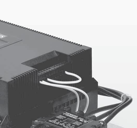
4 Step 1. Turn off the three phase and control power to the Elevator Starter. Step 2. Remove the Control Power Terminal Block located on the right-hand side of the Elevator Starter. Step 3. Remove the 4 housing screws from the corners of the plastic cover. he Step 4. Remove the plastic cover from the Elevator Starter. Ribbon cable Grounding screw Class 72G Elevator Starter Installation Guide 3


5 Step 5. Ribbon Cable Connector Connector in Closed Position Connector in Open Position Step 6. Unscrew and remove the grounding screw from the logic board Step 7. Unscrew and remove the housing support stand-off. Step 8. Remove the logic board from the Elevator Starter. Step 9. While taking standard ESD precautions, remove the replacement logic s ield ba and place it on t e plastic st nd-o fs Step 10. Insert the housing support stand-off and hand tighten. Step 11. Insert the grounding screw and tighten to 8-12 in-lbs. 4 Class 72G Elevator Starter Installation Guide

6 Step 12. Carefully insert the ribbon cable into the logic board connector and close the latch. Ribbon Cable Wire Leads Attention: Make sure the ribbon cable s wire leads are inserted properly into the connector or the unit will not function correctly. Step 13. Place the plastic cover on top of the Elevator Starter. Step 14. Insert the 4 housing screws into the plastic cover and tighten to in-lbs. Step 15. Insert the Control Power Terminal Block into the Elevator Starter. Step 16. Turn on three phase and control power to the Elevator Starter. If the LCD display remains blank or displays a fault, please consult your original instruction manual or call Siemens tech support at: Class 72G Elevator Starter Installation Guide 5

7 Attention: Steps must be performed to ensure that the replacement logic board is correctly configured for your Elevator Starter s Rated Amps. Step 17. Using the keypad, go to the Password screen in the System menu on the display and enter Status Menu Left Arrow MOTOR STATUS STOPPED System Menu Right Arrow Reset Fault RESET OFF Down Arrow Password 0 Step 18. Go to the Reset Defaults screen in the OEM menu and change to RESET ON. System Menu Left Arrow Password 0 Down Arrow OEM Menu Right Arrow Reset ault RESET OFF 6 Class 72G Elevator Starter Installation Guide

8 Step 19. For return of your old logic board, please contact your original OEM support group or and return request to: A return label is included with your logic board kit for your convienence. Please complete the return label information and apply to the return package. Also a second software version label is included. This should be applied as shown directly under the Control Power Terminal Block label as shown below Placement of New Software Label Step 20. Congratulations! You have successfully replaced the logic board on your Elevator Starter. Class 72G Elevator Starter Installation Guide 7
9 Siemens Industry, Inc. Industry Automation Division 3333 Old Milton Parkway Alpharetta, GA Subject to change without prior notice. Order No: SFIS-72GLB- All rights reserved. Printed in USA 201 Siemens Industry, Inc. The information provided in this brochure contains merely general descriptions or characteristics of performance which in case of actual use do not always apply as described or which may change as a result of further development of the products. An obligation to provide the respective characteristics shall only exist if expressly agreed in the terms of contract. All product designations may be trademarks or product names of Siemens AG or supplier companies whose use by third parties for their own purposes could violate the rights of the owners.
Shutter Assembly Guide Frame Accessory
 Shutter Assembly Guide Frame Accessory SIZE: FS1 3-pole Cat. No.: WLG3SHUT1L For Use With: Circuit Breaker Adapters WLG _ 13 Installation Instructions Instruction No.: 923 99902 176 Danger Peligro Danger!
SINAMICS G130. Terminal Module 150 (TM150) Operating Instructions 03/2013 SINAMICS
 Operating Instructions 03/2013 SINAMICS") SINAMICS G130 Operating Instructions 03/2013 SINAMICS s Safety information 1 General information 2 SINAMICS SINAMICS G130 Mechanical installation 3 Electrical installation 4 Technical specifications 5
SINAMICS G130 Operating Instructions 03/2013 SINAMICS s Safety information 1 General information 2 SINAMICS SINAMICS G130 Mechanical installation 3 Electrical installation 4 Technical specifications 5
Safety is a SIRIUS business
 SIRIUS 3SK Safety Relays Safety is a SIRIUS business Safety Relays for compact safety applications usa.siemens.com/safety-relays Safety is a SIRIUS business Machines can be dangerous. Personnel need to
COM32. Installation & Operation Manual
 COM32 Installation & Operation Manual DANGER ElectricaI equipment contains hazardous voltages and high speed moving parts. Can cause death, serious injury or property damage. See safety instruction contained
Line reactors SINAMICS. SINAMICS G120P Line reactors. Safety information 1. General. Mechanical installation 3. Electrical installation 4
 Safety information 1 General 2 SINAMICS SINAMICS G120P Mechanical installation 3 Electrical installation 4 Technical specifications 5 Operating Instructions Control version V4.6 11/2013 A5E32845290B AA
SINAMICS G130. Voltage Sensing Module 10 (VSM10) Operating instructions 03/2011 SINAMICS
 Operating instructions 03/2011 SINAMICS") SINAMICS G130 Operating instructions 03/2011 SINAMICS s Safety information 1 General 2 SINAMICS SINAMICS G130 Voltage Sensing Module 10 (VSM10) Mechanical installation 3 Electrical installation 4 Technical
SINAMICS G130 Operating instructions 03/2011 SINAMICS s Safety information 1 General 2 SINAMICS SINAMICS G130 Voltage Sensing Module 10 (VSM10) Mechanical installation 3 Electrical installation 4 Technical
Installation Guide SMT 2200/3000 VA Input/Output Hardwire Kit
 Installation Guide SMT 2200/3000 VA Input/Output Hardwire Kit Important Safety Messages SAVE THESE INSTRUCTIONS - This section contains important instructions that should be followed during installation
SINAMICS. SINAMICS G120P dv/dt filter plus Voltage Peak Limiter. Safety information 1. General. Mechanical installation. Electrical installation 4
 Safety information 1 General 2 SINAMICS SINAMICS G120P dv/dt filter plus Voltage Peak Limiter Operating Instructions Mechanical installation 3 Electrical installation 4 Maintenance and servicing 5 Technical
SINAMICS G130. Voltage Sensing Module 10 (VSM10) Operating Instructions 05/2010 SINAMICS
 Operating Instructions 05/2010 SINAMICS") SINAMICS G130 Operating Instructions 05/2010 SINAMICS s Safety information 1 General 2 SINAMICS SINAMICS G130 Voltage Sensing Module 10 (VSM10) Mechanical installation 3 Electrical installation 4 Technical
SINAMICS G130 Operating Instructions 05/2010 SINAMICS s Safety information 1 General 2 SINAMICS SINAMICS G130 Voltage Sensing Module 10 (VSM10) Mechanical installation 3 Electrical installation 4 Technical
COOPER POWER SERIES. Input/Output (I/O) module installation instructions. Voltage Regulators MN225067EN
 module installation instructions. Voltage Regulators MN225067EN") Voltage Regulators MN225067EN Effective November 2016 Supersedes June 2014 (S225-70-13) COOPER POWER Input/Output (I/O) module installation instructions SERIES DISCLAIMER OF WARRANTIES AND LIMITATION OF
Voltage Regulators MN225067EN Effective November 2016 Supersedes June 2014 (S225-70-13) COOPER POWER Input/Output (I/O) module installation instructions SERIES DISCLAIMER OF WARRANTIES AND LIMITATION OF
SITRANS F. Flowmeters SysCom Upgrade Kit IP65 (NEMA 4X) Multi-Channel. Introduction 1. Installing/Mounting 2. Hardware Installation Instructions
 Multi-Channel. Introduction 1. Installing/Mounting 2. Hardware Installation Instructions") Introduction 1 Installing/Mounting 2 SITRANS F Flowmeters SysCom Upgrade Kit IP65 (NEMA 4X) Multi-Channel Hardware Installation Instructions 1/2010 A5E02518333A Revision 04 Legal information Warning notice
Introduction 1 Installing/Mounting 2 SITRANS F Flowmeters SysCom Upgrade Kit IP65 (NEMA 4X) Multi-Channel Hardware Installation Instructions 1/2010 A5E02518333A Revision 04 Legal information Warning notice
SIMADYN D Digital Control System. Fiber-Optic Rack Coupling CS12. User Manual. Edition DK No
 SIMADYN D Digital Control System User Manual Fiber-Optic Rack Coupling CS12 Edition 05.95 DK No. 237741 User Manual, Fiber-Optic Rack Coupling CS12 Edition Status 1 Fiber-Optic Rack Coupling CS12 05.95
dv/dt filter compact plus Voltage Peak Limiter SINAMICS SINAMICS G120P dv/dt filter compact plus Voltage Peak Limiter Safety information 1 General 2
 dv/dt filter compact plus Voltage Peak Limiter SINAMICS SINAMICS G120P dv/dt filter compact plus Voltage Peak Limiter Operating Instructions Safety information 1 General 2 Mechanical installation 3 Electrical
WARNING ELECTRICAL SHOCK HAZARD
 Description Safety Instructions The top-entry sub D9 connector kit is designed for enclosure sizes D1h D8h, E1 E2, and E1h E4h with VLT PROFIBUS DP MCA 101 option. It fits the following drives: VLT HVAC
Coolwave 2 Control Board Upgrade Kit
 Instruction Sheet P/N 1612622-01 Coolwave 2 Control Board Upgrade Kit NOTE: Retain the box used for shipping the control board and contactor to comply with the conditions of warranty. WARNING: Allow only
GV3000/SE AC Drive ControlNet Network Communication Option Board M/N 2CN3000
 GV3000/SE AC Drive ControlNet Network Communication Option Board M/N 2CN3000 Instruction Manual D2-3390-2 The information in this manual is subject to change without notice. Throughout this manual, the
Industrial Controls. Motor management and control devices SIMOCODE pro - Application examples. Introduction 1. Application example
 Introduction 1 Application example 2 Industrial Controls Motor management and control devices SIMOCODE pro - Application examples Application Manual Example circuits control functions 3 Further application
COOPER POWER SERIES. 600 A U-OP visible break connector system operation instructions. Deadbreak Apparatus Connectors MN650022EN
 Deadbreak Apparatus Connectors MN650022EN COOPER POWER Effective March 2016 Supersedes S600-14-1 June 2010 SERIES 600 A U-OP visible break connector system operation instructions DISCLAIMER OF WARRANTIES
SIMATIC. Process Control System PCS 7 PCS 7 system documentation - Readme V8.0 SP2 (Update 1) Options for Accessing Documentation 1
 Options for Accessing Documentation 1") Options for Accessing Documentation 1 Notes on the Product Documentation 2 SIMATIC Notes on the PCS 7 V8.0 SP2 system documentation 3 Process Control System PCS 7 PCS 7 system documentation - Readme V8.0
Options for Accessing Documentation 1 Notes on the Product Documentation 2 SIMATIC Notes on the PCS 7 V8.0 SP2 system documentation 3 Process Control System PCS 7 PCS 7 system documentation - Readme V8.0
Installing and Configuring Rialto Analytic Appliances
 Installing and Configuring Rialto Analytic Appliances Important Safety Information This manual provides installation and operation information and precautions for the use of this camera. Incorrect installation
5521 Potentiometer Analog Input Module
 55 Potentiometer Analog Input Installation, Operation and Maintenance Setup Manual 5/9/0 Safety Information The information provided in this documentation contains general descriptions and/or technical
Readme SiVArc V14 SP1 Update 6
 Product version 1 Improvements in Update 6 2 Readme 05/2018 Legal information Warning notice system This manual contains notices you have to observe in order to ensure your personal safety, as well as
Installation Instructions
 Installation Instructions Variable Frequency Drive (VFD) 7 ½ - 25 Ton Units with 2 Wire Control WARNING UNINTENDED EQUIPMENT OPERATION Modifying or changing parame eters whose function is not described
Team engineering via Inter Project. Engineering. TIA Portal. Team engineering via Inter Project Engineering. Basics of "Inter Project Engineering"
 Team engineering via Inter Project Engineering TIA Portal Basics of "Inter Project Engineering" 1 Creating an IPE file 2 Importing an IPE file 3 Team engineering via Inter Project Engineering Getting Started
Smart Mode Measurements
 Smart Mode Measurements Technical Reference for Maintenance PME 7.2.3 V1.0 Safety Information Important Information Read these instructions carefully before trying to install, configure, or operate this
ACCESS 9340/9360 Meter Input/Output Module
 Installation Manual PMIM-IOMOD-0208 ACCESS 9340/9360 Meter Input/Output Module 9340-60-I/O2222 and 9340-60-I/O26 HAZARD CATEGORIES AND SPECIAL SYMBOLS Read these instructions carefully and look at the
SEL-3421 Motor Relay HMI (With LCD) Quick-Start Guide
 Quick-Start Guide") SEL-3421 Motor Relay HMI (With LCD) Quick-Start Guide Overview The SEL-3421 Motor Relay HMI can: Read metering and monitoring data. Inspect targets. Control relay operations. Display diagnostics. Display,
SEL-3421 Motor Relay HMI (With LCD) Quick-Start Guide Overview The SEL-3421 Motor Relay HMI can: Read metering and monitoring data. Inspect targets. Control relay operations. Display diagnostics. Display,
Analog Input Installation Manual
 Analog Input Installation Manual August 2011 Part Number: 144-23917 Copyright 2011 Magnetek 1. Preface and Safety Magnetek manufactures products used as components in a wide variety of industrial systems
Change Report Colors and Logo
 How to Change Report Colors and Logo Report Developer Kit V1.0 Safety Information Important Information Read these instructions carefully before trying to install, configure, or operate this software.
COOPER POWER SERIES. RS-485 digital communications accessory board installation and operation instructions. Voltage Regulators MN225074EN
 Voltage Regulators MN225074EN Effective March 2017 Supersedes January 2012 (S225-40-7) RS-485 digital communications accessory board installation and operation instructions COOPER POWER SERIES DISCLAIMER
SEM3 - Embedded Micro Metering Module
 SEM - Embedded Micro Metering Module Quick Reference Guide and Installation Instructions Scan QR Code for more information usa.siemens.com/sem Installation! DANGER Hazardous Voltage. Will cause death or
MindSphere. Visual Explorer. Introduction. User roles for "Visual Explorer" Connecting "Visual Explorer" to MindSphere data. Creating Visualizations
 Introduction 1 User roles for "Visual Explorer" 2 MindSphere Connecting "" to MindSphere data 3 Creating Visualizations 4 Getting Started 06/2018 Legal information Warning notice system This manual contains
Siemens Industrial s
 SINAMICS G130 Operating Instructions 05/2010 SINAMICS Siemens Industrial s Sinusoidal filter Safety information 1 General 2 SINAMICS SINAMICS G130 Mechanical installation 3 Electrical installation 4 Technical
Instruction Sheet WPC 2000 Option 1
 Instruction Sheet WPC 2000 Option 1 This document shows you how to install, wire, program, monitor, and troubleshoot WPC 2000 Option 1. Option 1 is compatible with WPC 2000 systems running WPC 2000 version
LXM32. Explanation for detected error E 733F. Expert Support Machine Solution
 LXM32 Explanation for detected error E 733F Expert Support Machine Solution The information provided in this documentation contains general descriptions and/or technical characteristics of the performance
Chore-Tronics Mobile Server
 Chore-Tronics Mobile Server Installation & Operator s Instruction Manual Contact your nearby Chore-Time distributor or representative for additional parts and information. Chore-Time Group A division of
PowerLogic ION7550 RTU option
 70052-0213-02 PRODUCT OPTION 01/2011 PowerLogic ION7550 RTU option The PowerLogic ION7550 Remote Terminal Unit (RTU) option is designed for data acquisition from WAGES (water, air, gas, electricity, steam)
Configurable Output Distribution. 120V / 208V / 240V 60Hz. User Manual English
 Configurable Output Distribution 120V / 208V / 240V 60Hz User Manual English TABLE OF CONTENTS IMPORTANT SAFETY INSTRUCTIONS.......................... 1 GLOSSARY OF SYMBOLS....................................
Siemens Drives & PLCs
 SIMATIC HMI Configuring Text-based Displays Table of Contents Introduction Commissioning Operating Units Product Brief Basic Steps for a Configuration Extend Configuration with Simple Elements Edition
EMMS-T A00 SIERS. Siemens integrated electrical racking system instruction manual. usa.siemens.com/mvswitchgear
 EMMS-T40013-01-4A00 SIERS Siemens integrated electrical racking system instruction manual usa.siemens.com/mvswitchgear SIERS Siemens Integrated Electrical Racking System Instruction Manual Hazardous voltages
To Purchase This Item, Visit BMI Gaming (800)
") OWNERS AND SERVICE MANUAL INNOVATIVE CONCEPTS IN ENTERTAINMENT INC. 10123 MAIN STREET, CLARENCE, NY 14031 SERVICE: 1-716-759-0360 FAX: 1-716-759-0884 E-MAIL: service@icegame.com WEBSITE: www.icegame.com
OWNERS AND SERVICE MANUAL INNOVATIVE CONCEPTS IN ENTERTAINMENT INC. 10123 MAIN STREET, CLARENCE, NY 14031 SERVICE: 1-716-759-0360 FAX: 1-716-759-0884 E-MAIL: service@icegame.com WEBSITE: www.icegame.com
Analog Monitor Installation Manual
 Analog Monitor Installation Manual Part Number: 144-23919 Copyright 2011 Magnetek 1. Preface and Safety Magnetek manufactures products used as components in a wide variety of industrial systems and equipment.
SIMATIC S Getting Started for First Time Users. Order No.: 6ZB5310-0NC02-0BA0 04/2007 A5E
 SIMATIC S7-300 Getting Started for First Time Users Order No.: 6ZB5310-0NC02-0BA0 04/2007 A5E01094750-01 Safety Guidelines This manual contains notices you have to observe in order to ensure your personal
Electrical network protection Sepam series 20 Sepam series 40 Quick start
 03146790FE+01+NP00000000 Electrical network protection Sepam series 20 Sepam series 40 Quick start PE50465 Storage Sepam may be stored in its original packaging in a closed sheltered location: b ambient
COOPER POWER SERIES. Visible-Break switch accessory operation instructions. Padmounted switchgear MN285011EN
 Padmounted switchgear MN285011EN Effective May 2017 Supersedes November 2004 (S285-10-4) Visible-Break switch accessory operation instructions COOPER POWER SERIES DISCLAIMER OF WARRANTIES AND LIMITATION
SURGE PROTECTION USER MANUAL. Surge Protection Device PORTABLE POWER DISTRIBUTION SURGE PROTECTION DEVICE (SPD) B
 B") SURGE PROTECTION PORTABLE POWER DISTRIBUTION SURGE PROTECTION DEVICE (SPD) USER MANUAL Surge Protection Device B 01 156 9000 This Surge Protection Device is intended for professional use only Read this
SURGE PROTECTION PORTABLE POWER DISTRIBUTION SURGE PROTECTION DEVICE (SPD) USER MANUAL Surge Protection Device B 01 156 9000 This Surge Protection Device is intended for professional use only Read this
5504 Thermocouple Analog Input Module
 550 Thermocouple Analog Input Installation, Operation and Maintenance Setup Manual 5/9/0 Safety Information The information provided in this documentation contains general descriptions and/or technical
Manual Version: V1.00. Video Decoder Quick Guide
 Manual Version: V1.00 Video Decoder Quick Guide Thank you for purchasing our product. If there are any questions, or requests, please do not hesitate to contact the dealer. Copyright Copyright 2016 Zhejiang
Model 2460-KIT. Screw Terminal Connector Kit. Description / September 2014 *P * 1
 Keithley Instruments 28775 Aurora Road Cleveland, Ohio 44139 1-800-935-5595 http://www.keithley.com Model 2460-KIT Screw Terminal Connector Kit Description The Model 2460-KIT Screw Terminal Connector Kit
VLT Line Filter MCC 107 EMC Filter Series VLT Midi Drive FC 280 (K1 K3)
") These instructions provide technical and installation information for the MCC 107 EMC filter series. Only Danfoss qualified personnel is allowed to install this equipment. The personnel must be familiar
These instructions provide technical and installation information for the MCC 107 EMC filter series. Only Danfoss qualified personnel is allowed to install this equipment. The personnel must be familiar
Software Installation Guide
 KGASD0301APM APM FOR WINDOWS Software Installation Guide NOTE: Read the entire Software Installation Guide before using the APM for Windows software. SAFETY CONSIDERATIONS Installing and servicing heating
Options for ABB drives, converters and inverters. User s manual FEA-03 F-series extension adapter
 Options for ABB drives, converters and inverters User s manual FEA-03 F-series extension adapter List of related manuals Option manuals and guides FEA-03 F-series extension adapter user s manual FDCO-01/02
300XAC. Quick Start Guide. Modular AC Power Source MODELS 310XAC, 320XAC, 340XAC, 360XAC
 00XAC Quick Start Guide Modular AC Power Source MODELS 0XAC, 0XAC, 40XAC, 60XAC POWER CHECKLIST Power down output while connections are made. Output & input cabling have unique AWG carrying capacity. (Be
Getting Started - Startdrive. Startdrive SINAMICS. Introduction 1. Connecting the drive unit to the PC. Creating a project 3
 Getting Started - Startdrive Introduction 1 Connecting the drive unit to the PC 2 Startdrive SINAMICS Getting Started Creating a project 3 Going online and incorporating devices 4 Commissioning the drive
General Information 1. Connection 2. User Interface 3 ATC5300. Menus 4. Automatic Transfer Controller. Remote Control Software Manual A5E
 s General Information 1 Connection 2 Automatic Transfer Controller User Interface 3 Menus 4 Remote Control Software Manual Edition 01/2010 A5E02469028-01 Legal information Warning notice system This manual
Source-Transfer Application Guide
 S&C Model 6802 Automatic Switch Control Source-Transfer Application Guide Table of Contents Section Page Section Page Introduction Qualified Persons.... 2 Read this Instruction Sheet.... 2 Retain this
InView Firmware Update
 Installation Instructions InView Firmware Update Topic Page Hazardous Voltage 3 Change EPROM on 2706-P72, 2706-P74 Display 3 Change EPROM on 2706-P42, 2706-P44 Displays 5 Firmware Upgrade Kit 7 2 InView
INSTALLATION INSTRUCTIONS STZ-R SERIES (ENGLISH)
") Surge-Trap STZ-R series Surge Protective Device (SPD) Danger Hazard of Electrical Shock, Explosion or Arc Flash Only qualified licensed electricians should install or service SPDs Verify that all power
Surge-Trap STZ-R series Surge Protective Device (SPD) Danger Hazard of Electrical Shock, Explosion or Arc Flash Only qualified licensed electricians should install or service SPDs Verify that all power
BaseUnits (6ES7193-6BP.../3RK1908-0AP00 ) SIMATIC. ET 200SP BaseUnits. Preface. Guide to the documentation 1. Product overview 2
 SIMATIC. ET 200SP BaseUnits. Preface. Guide to the documentation 1. Product overview 2") BaseUnits (6ES7193-6BP.../3RK1908-0AP00 ) SIMATIC ET 200SP BaseUnits (6ES7193-6BP.../3RK1908-0AP00 ) Manual Preface Guide to the documentation 1 Product overview 2 BaseUnits for I/O modules 3 BaseUnits
BaseUnits (6ES7193-6BP.../3RK1908-0AP00 ) SIMATIC ET 200SP BaseUnits (6ES7193-6BP.../3RK1908-0AP00 ) Manual Preface Guide to the documentation 1 Product overview 2 BaseUnits for I/O modules 3 BaseUnits
Altivar 61/71 Adjustable Speed Drives Heatsink Fan Kits VZ3V1212 and VZ3V1216
 Altivar 61/71 Adjustable Speed Drives Heatsink Fan Kits VZ3V1212 and VZ3V1216 Instruction Bulletin 30072-452-48 Retain for future use. 30072-452-48 Altivar 61/71 Heatsink Fan Kits VZ3V1212 and VZ3V1216
User Guide usa.siemens.com/smartgear
 Siemens Sm@rt DAS User Guide usa.siemens.com/smartgear Sm@rt DAS Safety Precautions (a) Only qualified persons familiar with the construction and operation of this equipment should perform work describedin
3700 SERIES USER MANUAL
 SAFETY GUIDE This manual contains the precautions necessary to ensure your personal safety as well as for protection for the products and the connected equipment. These precautions are highlighted with
PS/IO Circuit Board Retrofit
 S&C 6800 Series Automatic Switch Controls PS/IO Circuit Board Retrofit Table of Contents Section Page Introduction Qualified Persons.... 2 Read this Instruction Sheet.... 2 Retain this Instruction Sheet....
COMOS. Platform Class documentation RevisionMaster_dll. Class: RevisionInfo 1. Class: RevisionMaster 2. Programming Manual
 Class: RevisionInfo 1 Class: RevisionMaster 2 COMOS Platform Class documentation RevisionMaster_dll Programming Manual 03/2017 V10.2.1 A5E39859923-AA Legal information Warning notice system This manual
Omnitron Systems Technology, Inc. 1. iconverter. 19-Module Managed Power Chassis User s Manual
 Omnitron Systems Technology, Inc. 1 iconverter 19-Module Managed Power Chassis User s Manual 27 Mauchly, #201, Irvine, CA 92618 Phone: (949) 250-6510; Fax: (949) 250-6514 2 Omnitron Systems Technology,
TLA5Fxxx, TLA62F0x, & TLA7Fxxx PowerFlex Field Upgrade Kit Logic Analyzers Instructions
 xx ZZZ TLA5Fxxx, TLA62F0x, & TLA7Fxxx PowerFlex Field Upgrade Kit Logic Analyzers Instructions www.tektronix.com *P077059110* 077-0591-10 Copyright Tektronix. All rights reserved. Licensed software products
Application Guide. M 2174B Moloney Replacement Adapter Panel
 Application Guide M 174B Moloney Replacement Adapter Panel CONTROLS Replacement Panel M 174B Adapts M 001 Series Digital Tapchanger Control to Replace Moloney/Tempo LTC Control Panel Connects easily to
Multi-Loader. User manual 06/ BBV48778
 Multi-Loader User manual 06/2009 BBV48778 www.schneider-electric.com Contents Important information 4 Before you begin 5 Documentation structure 6 Setup procedure 7 Introduction 8 Receipt of the Multi-Loader
Conext CL-60 Inverter Firmware Upgrade Process
 Conext CL-60 Inverter Firmware Upgrade Process http://solar.schneider-electric.com 976-0380-01-01/B August 2017 Application Note EXCLUSION FOR DOCUMENTATION UNLESS SPECIFICALLY AGREED TO IN WRITING, SELLER
Model 7705 Control Module
 www.keithley.com Model 7705 Control Module User s Guide PA-696 Rev. D / October 2006 A G R E A T E R M E A S U R E O F C O N F I D E N C E Safety Precautions The following safety precautions should be
EPROM Replacement for Contrbl Systems
 EPROM Replacement 1 EPROM Replacement for OmniScan@ Contrbl Systems Important 0 Before starting, read all instruction sheets that have been provided with your service kit It is recommended that you use
Your Global Flow Control Partner. Series 50 Valve Status Monitor Operation and Maintenance Manual
 Your Global Flow Control Partner Series 50 Valve Status Monitor Table of Contents 1. Definition of Terms... 2 2. Safety... 2 3. Storage... 3 4. Commissioning... 3 4.1. Mounting your VSM... 3 4.2. Wiring
SIMATIC HMI. Configuring Graphics Displays. Product Brief. Edition 12/01. Table of Contents. Introduction. Commissioning Operating Units
 SIMATIC HMI Configuring Graphics Displays Table of Contents Introduction Commissioning Operating Units Product Brief Basic Steps for a Configuration Extend Configuration with Simple Elements Edition 12/01
A0/A1 Controller Assembly Operation/Installation Manual READ AND FOLLOW ALL SAFETY INSTRUCTIONS
 Document Number: 9100-127-2301-99 Release Date: 2/2/15 A0/A1 Controller Assembly Operation/Installation Manual READ AND FOLLOW ALL SAFETY INSTRUCTIONS DO NOT let any supply cords touch hot surfaces higher
IntelliVue Patient Monitors
 Hardware Upgrade Installation Guide IntelliVue Patient Monitors MX400/MX450 Patient Monitoring 1Table of Contents 1 Introduction 5 What is in this Installation Note 6 2 Checking your Tools and Kit Hardware
LINE VOLTAGE TESTER CT101 USER S MANUAL. Please read this manual carefully and thoroughly before using this product.
 LINE VOLTAGE TESTER USER S MANUAL CT101 Please read this manual carefully and thoroughly before using this product. KEY FEATURES Visual indication of AC or DC voltage Easy to use approved Safe for CAT
WARNING ELECTRICAL SHOCK HAZARD
 1 Product Overview These instructions provide information about installation of finger guard kits. The instructions are targeted at users already familiar with the VLT Soft Starters MCD 500, or VLT Compact
COM128. Installation & Operation Manual
 COM128 Installation & Operation Manual DANGER ElectricaI equipment contains hazardous voltages and high speed moving parts. Can cause death, serious injury or property damage. See safety instruction contained
Industrial Controls. Motor management and control devices SIMOCODE pro. Introduction 1. Configuring a reversing starter. List of abbreviations
 Introduction 1 Configuring a reversing starter 2 Industrial Controls A List of abbreviations Motor management and control devices Getting Started 05/2018 A5E40507294002A/RS-AB/002 Legal information Warning
Class documentation. COMOSKDictionary COMOS. Platform Class documentation COMOSKDictionary. Trademarks. General. KDictionary. Programming Manual
 Class documentation COMOSKDictionary COMOS Trademarks 1 General 2 KDictionary 3 Platform Class documentation COMOSKDictionary Programming Manual 04/2012 A5E03777026-01 Legal information Legal information
PowerLogic ION7300 Series
 PowerLogic ION7300 Series Power and Energy Meter Advanced Field Retrofit Instructions August 2006 Danger This symbol indicates the presence of dangerous voltage within and outside the product enclosure
Installation and Operation Guide for PD5200 and PD5300 Automatic Transfer Switch
 Installation and Operation Guide for PD5200 and PD5300 Automatic Transfer Switch PD52 PD52S & PD52DCS PD53-100 te: The PD52S & PD52DCS are provided with LED lights. The GREEN LIGHTS indicate Shore Power
SCXI HIGH-VOLTAGE 8 4 MATRIX TERMINAL BLOCK
 INSTALLATION GUIDE SCXI -1332 HIGH-VOLTAGE 8 4 MATRIX TERMINAL BLOCK Introduction This guide describes how to install and use the SCXI-1332 terminal block with your SCXI-1127 module. The SCXI-1332 terminal
PRO1250D CT MID DIN rail three phase four wire energy meter. User manual Version 1.5
 PRO1250D CT MID DIN rail three phase four wire energy meter. User manual Version 1.5 1 Safety instructions...3 2 Foreword...4 3 CE certificates...5 4 MID certificate...7 5 Performance criteria...8 6 Specifications...8
PRO-1250D CT MID DIN rail three phase four wire energy meter.
 PRO-1250D CT MID DIN rail three phase four wire energy meter. 1.1 Safety instructions 1.2 Foreword 1.3 MID certificate 1.4 Performance criteria 1.5 Specifications 1.6 Basic errors 1.7 Description 1.8 Dimensions
SIRIUS Overload Relays. SIRIUS 3RB24 Solid-State Overload Relays with Complete Starter Functionality via IO-Link
 Integrated Motor Protection for High-Feature Applications SIRIUS 3RB24 Solid-State Overload Relays with Complete Starter Functionality via IO-Link SIRIUS Overload Relays www.siemens.com/sirius SIRIUS 3RB24
DPM Active Harmonic Filter Quick Start Instructions
 DPM Active Harmonic Filter Quick Start Instructions These instructions will guide you through installing, testing your installation, and starting up your DPM. For additional information please refer to
SITOP power supply. Selectivity modules. Overview. Safety notes. Description, device design, dimension drawing. Mounting/removal 3
 Overview Safety notes 1 SITOP power supply Manual Description, device design, dimension drawing 2 Mounting/removal 3 Mounting position, mounting clearances 4 Installation 5 Technical data 6 Safety, approvals,
M215 (M215-60) Safety
 Safety") M215 QUICK INSTALL GUIDE M215 (M215-60) Safety Important Safety Information This document contains important instructions to use during installation and maintenance of the Enphase M215 Microinverter. To
M215 QUICK INSTALL GUIDE M215 (M215-60) Safety Important Safety Information This document contains important instructions to use during installation and maintenance of the Enphase M215 Microinverter. To
Explosion-Protected Arc-Fault Protection ExAFCI Arc-Fault Circuit Interrupter
 Installation, Operation & Maintenance Sheet Explosion-Protected Arc-Fault Protection ExAFCI Arc-Fault Circuit Interrupter > Contents 1 Contents 1 Contents...2 2 General Information...2 2.1 Manufacturer...2
User's Guide. MiniTec TM Series Model MN25 MultiMeter
 User's Guide MiniTec TM Series Model MN25 MultiMeter Warranty EXTECH INSTRUMENTS CORPORATION warrants this instrument to be free of defects in parts and workmanship for one year from date of shipment (a
Installation Guide Modbus TCP Module
 ENGINEERING TOMORROW Installation Guide Modbus TCP Module VLT Compact Starter MCD 201/MCD 202 VLT Soft Starter MCD 500 vlt-drives.danfoss.com Contents Installation Guide Contents 1 Introduction 3 1.1
MDM 011-Z1 Regen Resistor
 MDM 011-Z1 Regen Resistor Date of creation: 10.04.2017 Version date: 10.04.2017 Article number: 09-402-011-Z1-E Publisher: SIGMATEK GmbH & Co KG A-5112 Lamprechtshausen Tel.: 06274/4321 Fax: 06274/4321-18
Advidia A-15 & A-35 Installation Manual
 Advidia A-15 & A-35 Installation Manual Thank you for purchasing our product. If there are any questions, or requests, please do not hesitate to contact the dealer. This manual may contain inaccuracies
SIRIUS 3RB24 Solid-State Overload Relays with Complete Starter Functionality via IO-Link
 SIRIUS 3RB24 Solid-State Overload Relays with Complete Starter Functionality via IO-Link Integrated Motor Protection for High-Feature Applications siemens.com/sirius Answers for industry. SIRIUS 3RB24
SIMATIC. S7/HMI SIMATIC Automation Tool V3.1 SP1 product information. SIMATIC Automation Tool features 1. Known problems. Product Information
 SIMATIC Automation Tool features 1 Known problems 2 SIMATIC S7/HMI SIMATIC Automation Tool V3.1 SP1 product information Product Information V3.1 SP1, 05/2018 A5E43714043-AA Legal information Warning notice
Installation Instructions
 50ES, 50EZ, 50GL, 50GS, 50GX, 50JS, 50JX, 50JZ, 50SD, 50SZ, 50VL, 50VT, 50XP, 50XZ 601A, 602A, 602B, 604A, 604B, 604D, 607C, 701A, 702A, 702B, 704A, 704B, 704D, 707C PA1P, PA2P, PA3P, PH1P, PH2P, PH3P
INSTALLATION INSTRUCTIONS
 INSTALLATION INSTRUCTIONS BACnet Communication Card RXRX-AY01 RECOGNIZE THIS SYMBOL AS AN INDICATION OF IMPORTANT SAFETY INFORMATION! WARNING THESE INSTRUCTIONS ARE INTENDED AS AN AID TO QUALIFIED, LICENSED
Series Amp Pad Mount Quick Connect Input and Output Power Panels
 Series 300 2000-4000 Amp Pad Mount Quick Connect Input and Output Power Panels DANGER is used in this manual to warn of a hazard situation which, if not avoided, will result in death or serious injury.
SmartVFD Disconnect Panel Assemblies
 SmartVFD Panel Assemblies INSTALLATION INSTRUCTIONS APPLICATION Only The SmartVFD Panel Assemblies channel electrical power either through or around the variable frequency drive (VFD). INSTALLATION When