Functional safety manual Liquiphant M/S with FEL58 and Nivotester FTL325N
|
|
|
- Willis Walsh
- 5 years ago
- Views:
Transcription
1 T T SD00170F/00/EN/ Products Solutions Services Functional safety manual Liquiphant M/S with FEL58 and Nivotester FTL325N [Ex ia] [Ex ia] FTL325N FTL325N CH2 CH3 CH2 CH3 Level Limit Measuring System Application Minimum detection (also dry running protection) of all types of liquids in tanks to satisfy particular safety systems requirements as per IEC 61508/IEC The measuring device fulfils the requirements concerning For safety functions up to SIL 2 Explosion protection by intrinsic safety or flameproof enclosure EMC to EN and NAMUR Recommendation NE 21 Your benefits For minimum detection up to SIL 2 Independently assessed (Functional Assessment) by exida.com to IEC 61508/IEC Monitoring for corrosion on the tuning fork of the sensor No calibration Fault message for circuit break and short-circuit Functional test of subsequent devices at the push of a button Protected against outside vibration Easy commissioning
2 Table of contents SIL declaration of conformity Introduction General depiction of a safety system (protection function) Structure of the measuring system Level limit measuring system Safety function Permitted device types Safety function data Supplementary device documentation Settings and installation instructions Installation instructions Response in operation and failure Repair Recurrent function tests of the measuring system. 11 Appendix Specific values and wiring options for the measuring system Exida Management Summary Supplementary Documentation Endress+Hauser
3 SIL declaration of conformity SIL-14004a Endress+Hauser 3
4 SIL-14004a 4 Endress+Hauser
5 Introduction For general informationen about SIL please refer to: General depiction of a safety system (protection function) Parameter tables for determining Safety Integrity Level (SIL) The following tables are used to define the reachable SIL, the requirements pertaining to the Average Probability of Dangerous Failure on Demand (PFDavg), the Hardware Fault Tolerance (HFT) and the Safe Failure Fraction (SFF) of the safety system. The specific values for the Liquiphant M/S + Nivotester FTL325N measuring system can be found in the Appendix. Permitted probabilities of dangerous failures on demand of the complete safety related system dependent on the SIL (e.g. exceeding a defined MIN level/switch point) (Source: IEC 61508, Part 1): SIL PFD avg to < to < to < to < 10 1 The following table shows the achievable Safety Integrity Level (SIL) as a function of the probability fraction of safety-oriented failures and the "hardware fault tolerance" of the complete safety system for type B systems (complex components, not all faults are known or can be described). SFF HFT 0 1 (0) 1) 2 (1) 1 < 60% not allowed SIL 1 SIL 2 60% to < 90% SIL 1 SIL 2 SIL 3 90% to < 99% SIL 2 SIL 3 99% SIL 3 1) In accordance with IEC (FDIS) (Section ), the HFT can be reduced by one (values in brackets) if the devices used fulfil the following conditions: - the device is proven in use, - only process-relevant parameters can be changed at the device (e.g. measuring range,... ), - changing the process-relevant parameters is protected (e.g. password, jumper,... ), - the safety function requires less than SIL 4. All conditions apply to Liquiphant M/S + Nivotester FTL325N. Endress+Hauser 5
6 Structure of the measuring system Level limit measuring system The measuring system's devices are displayed in the following diagram (example). A B 1 2 [Ex ia] T FTL325 [Ex ia] FTL325 T CH2 CH3 CH2 CH3 1 FEL - Electronic insert A Nivotester FTL325N (one-channel) 2 Liquiphant M/S B Nivotester FTL325N (three-channel) A Safety function The safety function applies to all settings in MIN safety (monitoring of the covered state) and use of the NO contacts of the level relays. The following settings are permitted for the safety function: Device Setting As-delivered state Liquiphant Density switch setting: 0,5 Density switch setting: 0,7 "MIN" safety Density switch setting: 0,7 "MAX" safety Nivotester FTL325N-#3#3 Nivotester FTL325N-#1#1 Error current signal < 1,2 ma All settings except " S function" (see Section "Settings and installation instructions") The DIL switch for failure indication (short-circuit and cable break-monitoring) must be set into position ON. Error current signal < 1,2 ma The DIL switch for failure indication (short-circuit and cable break-monitoring) must be set into position ON. Error current signal < 1,2 ma Three-channel operation Failure switch "ON" Error current signal < 1,2 ma One-channel operation Failure switch "ON" The level relay always works in quiescent current safety; i.e. the relay releases when: the switch point is undershot (level falls below response height) a fault occurs the mains voltage fails In addition to the level relay, the alarm relay works in quiescent current safety and releases when: one of the following faults occurs: the sensor connection is interrupted the sensor connection short circuits the mains voltage fails When the alarm relay releases, the level relay also releases. 6 Endress+Hauser
7 Permitted device types The details pertaining to functional safety in this manual relate to the device versions listed below and are valid as of the specified firmware and hardware version. Unless otherwise specified, all subsequent versions can also be used for safety instrumented systems. A modification process according to IEC is applied for device changes. Valid device versions for safety-related use: Liquiphant M FTL50, FTL50H, FTL51, FTL51C, FTL51H+ FEL58 Feature Designation Option model 010 Approval all 020 Process connection all 030 Probe length; Type all 040 Electronics; Output 8 FEL58; SIL NAMUR+test button (H-L signal) 050 Housing; Cable entry all 060 Additional option all Valid firmware version: as of Valid hardware version (electronics): as of Valid device versions for safety-related use: Liquiphant S FTL70, FTL71+ FEL58 Feature Designation Option model 010 Approval all 020 Process connection all 030 Probe length all 040 Electronics; Output 8 FEL58; SIL NAMUR+test button (H-L signal) 050 Housing; Cable entry all 060 Additional option all 070 Application all Valid firmware version: as of Valid hardware version (electronics): as of Valid device versions for safety-related use: Nivotester FTL325N Feature Designation Option model 010 Approval G H N P T W ATEX II 3(1)G Ex nc/a (ia) IIC T4, SIL, IECEx Zone 2 ATEX II (1)GD (Ex ia) IIC, WHG, SIL, IECEx (Ex ia) IIC (Liquiphant M / Liquiphant S) NEPSI (Ex ia) IIC, SIL (Liquiphant M / Liquiphant S) FM IS Cl. I, II, III Div. 1 Gr. A-G, SIL (Liquiphant M / Liquiphant S) CSA IS Cl. I, II, III Div. 1 Gr. A-G, SIL (Liquiphant M / Liquiphant S) TIIS Ex ia IIC, SIL, labeling in Japan 020 Housing all 030 Power Supply all 040 Switch output all Endress+Hauser 7
8 Safety function data Supplementary device documentation The mandatory settings and data for the safety function can be found in chapter "Safety function", ä 6 and chapter "Settings and installation instructions", ä 10. The measuring system reacts in 0,9 s. MTTR is set at eight hours. Safety systems without a self-locking function must be monitored or set to an otherwise safe state after carrying out the safety function within MTTR. Liquiphant M FTL50, FTL50H, FTL51, FTL51H, FTL51C Documentation Contents Comment Technical Information FTL50, FTL50H, FTL51, FTL51H: TI00328F/00/EN FTL51C: TI00347F/00/EN Operating Instructions FTL50, FTL51: KA00143F/00/A6 KA00163F/00/A6 1) FTL50H, FTL51H: KA00144F/00/A6 KA00164F/00/A6 ) FTL51C: KA00162F/00/A6 KA00165F/00/A6 ) Safety instructions depending on the selected version "Approval" Technical data Accessories Installation Wiring Operation Commissioning Troubleshooting Repair Maintenance Safety, installation and operating instructions for devices, which are suitable for use in potentially explosive atmospheres or as overfill protection (WHG, German Water Resources Act). The documentation is available on the Internet: The documentation is supplied with the device. The documentation is also available on the Internet:. Additional safety instructions (XA, ZE) are supplied with certified device versions. Please refer to the nameplate for the relevant safety instructions. 1) with aluminium housing / separate terminal compartment. Liquiphant S FTL70, FTL71 Documentation Contents Comment Technical Information TI00354F/00/EN Operating Instructions KA00172F/00/A6 KA00173F/00/A6 1) Safety instructions depending on the selected version "Approval" Technical data Accessories Installation Wiring Operation Commissioning Troubleshooting Repair Maintenance Safety, installation and operating instructions for devices, which are suitable for use in potentially explosive atmospheres or as overfill protection (WHG, German Water Resources Act). The documentation is available on the Internet: The documentation is supplied with the device. The documentation is also available on the Internet:. Additional safety instructions (XA, ZE) are supplied with certified device versions. Please refer to the nameplate for the relevant safety instructions. 1) with aluminium housing / separate terminal compartment 8 Endress+Hauser
9 Nivotester FTL325N Documentation Contents Comment Technical Information TI00353F/00/EN Operating Instructions One-channel device: KA00170F/00/A6 Three-channel device: KA00171F/00/A6 Safety instructions depending on the selected version "Approval" Technical data Accessories Installation Wiring Operation Commissioning Troubleshooting Repair Maintenance Safety, installation and operating instructions for devices, which are suitable for use in potentially explosive atmospheres or as overfill protection (WHG, German Water Resources Act). The documentation is available on the Internet: The documentation is supplied with the device. The documentation is also available on the Internet:. Additional safety instructions (XA, ZE) are supplied with certified device versions. Please refer to the nameplate for the relevant safety instructions. Endress+Hauser 9
10 Settings and installation instructions Installation instructions Please refer to the Operating Instructions (KA) for information regarding the correct installation of Liquiphant M/S + Nivotester FTL325N. Since the application conditions have an effect on the safety of the measurement, pay attention to the notes in the Technical Information (TI) and Operating Instructions (KA). The ambient conditions for the Nivotester FTL325N must correspond to IP54 (in accordance with EN 60529). The manuals on setting the devices can be found in the section "Supplementary device documentation", ä 8. Settings for Liquiphant M/S (FEL58): The density switch setting must be configured according to the density range of the medium. The settings of the safety mode has an effect on the function. the DIL switch must be set to MIN for minimum detection in a SIL application. Settings for Nivotester FTL325N-#3#3 (three-channel version): Setting Description " Caution! CH2 Channel 2+3 in S function This setting ist not permitted for the safety function! s CH3 A CH3 CH2 s Channel 1, independent Channel 2+3 in S function Channel 1 is permitted for the safety function. The DIL switch for fault messaging (short-circuit and cable break-monitoring) must be set into possition ON. Channel 2 and 3 in this setting are not permitted for the safety function! A Observe the following for the Nivotester FTL325N: The operator must use suitable measures (e.g. current limiter, fuse) to ensure the relay contact characteristics are not exceeded: U 253 V AC 50/60 Hz, I 2 A, P 500 VA at cos 0,7 or U 40 V DC, I 2 A, P 80 W Changes to the measuring system and settings after start-up can impair the protection function! 10 Endress+Hauser
11 Response in operation and failure The response in operation and failure is descriped in the documentation, which can be found in the section "Supplementary device documentation", ä 8. Repair In the event of failure of a SIL-labeled Endress+Hauser device, which has been operated in a protection function, the "Declaration of Contamination and Cleaning" with the corresponding note "Used as SIL device in protection system" must be enclosed when the defective device is returned Recurrent function tests of the measuring system The operativeness of the minimum detection must be checked annually if the PFD avg values given in the Appendix are used. The check must be carried out in such a way that it is proven that the minimum detection functions perfectly in interaction with all components. This is guaranteed when the response height is lowered in an emptying process. If it is not practical to empty to the response height, suitable simulation of the level or of the physical measuring effect must be used to make the level sensor respond. If the operativeness of the level sensor / transmitter can be determined otherwise (exclusion of faults that impair function), the check can also be completed by simulating the corresponding output signal. In the case of recurrent tests, each permitted setting must be checked, especially whether all the alarm switches are set to ON. Note the following points for the function test: Each individual channel must be checked e.g. by lowering the level. Relay contact switching can be checked by using a hand multimeter at the terminals or by observing the minimum detection components (e.g. horn, adjuster). In multi-channel devices, all channels which do not carry out a safety function must be included in the recurrent function tests if faulty functioning cannot be detected by any other means. As a positive test result, an uncovered tuning fork must be detected and trigger the alarm for minimum detection. If fork uncovering is not detected during the recurrent test, the monitored process must be set to a safe state by means of additional or other measures and/or kept in the safe state until the safety system is repaired. Endress+Hauser 11
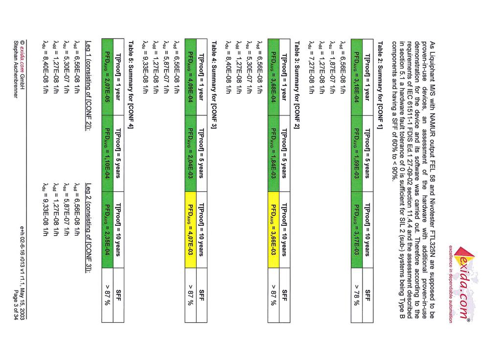
12 Appendix Specific values and wiring options for the measuring system The tables show the specific values and wiring options for the measuring system. Note the following points on the tables below: The PFD avg values for multichannel systems already contain common cause failures for the associated wiring scheme. The PFD avg values are only valid for the associated wiring scheme. Wiring schemes other than those shown in the Appendix were not assessed and thus do not bear any information relevant to safety. Using NC contacts instead of NO contacts requires further consideration of the installation means. The wiring scheme shows the number of devices (Liquiphant and Nivotester) and the limit relay contact circuits (open, when the sensor signals uncovering). For every channel, which performs a safety function, the failure indication (cable break/short circuit) must be switched on. With several devices in a wiring scheme, they all indicate the same displayed settings. For safety related use for MIN detection, the following application errors must be excluded: Liquiphant M/S: Permanent and/or heavy build-up or "non-newtonian media". Solid proportions of the medium with a diameter > 5.0 mm. (0.2 in). Corrosion: The Liquiphant may only be used in media to which the process-wetted parts are resistant. If coated sensors are used, measures must therefore be taken to ensure that there is no damage during installation and operation. The errors may cause that the demand mode of the safety function is not detected and the Liquiphant will not switch as intended. Liquiphant S: Hydrogen diffusion at temperatures over 180 C (356 F) and over 64 bar (928 psi). 12 Endress+Hauser
13 1oo1 architecture (CONF 1) Liquiphant (FEL58) Settings 1) Density 0,7 / 0,5 2) MIN safety Evaluated NAMUR transmitter A Error current signal < 1,2 ma SIL SIL 2 HFT 0 SFF 78.5% PFD avg ** 3.2 x 10⁻⁴ Wiring scheme A Ask the manufacturer in question for the NAMUR transmitter parameters relevant to safety. Recurrent test e.g. lowering the level ** TI (test interval) = annual PFD avg 1oo1D structure 3,50E-03 3,00E-03 2,50E-03 2,00E-03 1,50E-03 1,00E-03 5,00E-04 0,00E+00 0,0 2,0 4,0 6,0 8,0 10,0 PFD Test interval [years] A EN Endress+Hauser 13
14 1oo1 architecture (CONF 2) Liquiphant (FEL58) Settings 1) Density 0,7 / 0,5 2) MIN safety Nivotester FTL325N-#1#1 Settings (One-channel device) A Error current signal < 1,2 ma SIL SIL 2 HFT 0 SFF 87.9% PFD avg ** 3.7 x 10⁻⁴ Wiring scheme : A Recurrent test e.g. lowering the level ** TI (test interval) = annual PFD avg 1oo1D structure 4,00E-03 3,50E-03 3,00E-03 2,50E-03 2,00E-03 1,50E-03 1,00E-03 5,00E-04 0,00E+00 0,0 2,0 4,0 6,0 8,0 10,0 PFD Test interval [years] A EN 14 Endress+Hauser
15 1oo1 architecture (CONF 3) Liquiphant (FEL58) Settings 1) Desnity 0,7 / 0,5 2) MIN safety Nivotester FTL325N-#3#3 Settings (Three-channel device) A Error current signal < 1,2 ma SIL SIL 2 HFT 0 SFF 87.7% PFD avg ** 4.1 x 10⁻⁴ Wiring scheme CH2 CH3 CH2, CH3: A Recurrent test e.g. lowering the level ** TI (test interval) = annual PFD avg 1oo1D structure 4,50E-03 4,00E-03 3,50E-03 3,00E-03 2,50E-03 2,00E-03 1,50E-03 1,00E-03 5,00E-04 0,00E+00 0,0 2,0 4,0 6,0 8,0 10,0 PFD Test interval [years] A EN Endress+Hauser 15
16 1oo2 architecture (CONF 4) Liquiphant (FEL58) Settings 1) Density 0,7 / 0,5 2) MIN safety Nivotester FTL325N-#3#3 Settings (Three-channel device) A Error current signal < 1,2 ma SIL SIL 2 HFT 1 SFF 87.9% PFD avg ** 2.1 x 10⁻⁵ Wiring scheme CH2 CH3 + CH2 A Recurrent test e.g. lowering the level ** TI (test interval) = annual PFD avg 1oo2D structure 2,50E-04 2,00E-04 1,50E-04 PFD 1,00E-04 5,00E-05 0,00E+00 0,0 2,0 4,0 6,0 8,0 10,0 Test interval [years] A EN 16 Endress+Hauser
17 2oo3 architecture (CONF 5) Liquiphant (FEL58) Settings 1) Denisty 0,7 / 0,5 2) MIN safety Nivotester FTL325N-#3#3 Settings (Three-channel device) SIL SIL 2 HFT 1 SFF 87.3% PFD avg ** 2.4 x 10⁻⁵ A Error current signal < 1,2 ma Wiring scheme CH2 CH3 SPS 2oo3 Recurrent test e.g. lowering the level ** TI (test interval) = annual A PFD avg 2oo3D structure 3,50E-04 3,00E-04 2,50E-04 2,00E-04 1,50E-04 1,00E-04 5,00E-05 0,00E+00 0,0 2,0 4,0 6,0 8,0 10,0 PFD Test interval [years] A EN Endress+Hauser 17
18 1oo1 architecture (CONF 6) Liquiphant (FEL58) Settings 1) Density 0,7 / 0,5 2) MIN safety Nivotester FTL325N-#3#3 Settings (Three-channel device) CH3 CH2 s Error current signal < 1,2 ma A SIL SIL 2 HFT 0 SFF 87.9% PFD avg ** 3.7 x 10⁻⁴ Wiring scheme SIL : CH2 CH3 A Recurrent test e.g. lowering the level ** TI (test interval) = annual PFD avg 1oo1D structure 4,00E-03 3,50E-03 3,00E-03 2,50E-03 2,00E-03 1,50E-03 1,00E-03 5,00E-04 0,00E+00 0,0 2,0 4,0 6,0 8,0 10,0 PFD Test interval [years] A EN 18 Endress+Hauser

19 Exida Management Summary Exida Management Summary 2 Exida Management Summary 1 Endress+Hauser 19

20 Exida Management Summary 4 Exida Management Summary 4 20 Endress+Hauser
21 Supplementary Documentation Safety in the Process Industry - reducing risks with SIL CP01008Z/11/EN. Endress+Hauser 21
22 22 Endress+Hauser
23 Endress+Hauser 23
24
Soliphant M with electronic insert FEM54
 Functional safety manual Soliphant M with electronic insert FEM54 Level Limit Measuring System Application Overfill protection or operating maximum detection of all types of liquids in tanks to satisfy
Soliphant M with electronic insert FEM57 + Nivotester FTL325P
 T T Functional safety manual Soliphant M with electronic insert FEM57 + Nivotester FTL325P Level Limit Measuring System [Ex ia] FTL325P [Ex ia] FTL325P CH2 CH3 CH2 CH3 Application Overfill protection or
Special Documentation Soliphant M with electronic insert FEM57 + Nivotester FTL325P
 [Ex ia] CH1 CH1 [Ex ia] CH1 CH2 CH3 CH2 CH3 SD00207F/00/EN/13.15 71307734 Products Solutions Services Special Documentation Soliphant M with electronic insert FEM57 + Nivotester FTL325P Functional Safety
Proline Prowirl 72, 73
 Functional Safety Manual Vortex flow measuring system with 4 20 ma output signal Application Monitoring of maximum and/or minimum flow in systems which are required to comply with particular safety system
Functional safety manual RB223
 SD00011R/09/EN/13.13 71238251 Products Solutions Services Functional safety manual RB223 Passive barrier Application Galvanic isolation of active 0/4 to 20 ma signals from transmitters, valves and adjusters,
Micropilot M FMR230/231/232/233/240/244/245
 Functional Safety Manual Micropilot M FMR230/231/232/233/240/244/245 Level-Radar With 4...20 ma output signal Application Overspill protection or operating maximum detection of all types of liquids in
Special Documentation Liquicap M FMI51, FMI52
 SD00198F/00/EN/15.16 71315608 Products Solutions Services Special Documentation Liquicap M FMI51, FMI52 Functional Safety Manual Capacitance level measurement for liquids with a 4-20 ma output signal Table
Micropilot S FMR530/532/533, FMR540
 Order Code: Ser.-No.: Order Code: Ser.-No.: Functional Safety Manual Micropilot S FMR530/532/533, FMR540 Level-Radar with 4 to 20 ma Output Signal FMR533 FMR530 FMR540 FMR532 Application Operating minimum
Liquipoint T FTW31, FTW32
 TI00375F/00/EN/14.16 71336942 Products Solutions Services Technical Information Liquipoint T FTW31, FTW32 Conductive Point level switch for multiple point detection in conductive liquids Applications The
Functional Safety Manual Cerabar S PMC71, PMP71, PMP75
 SD00190P/00/EN/15.16 71344560 Products Solutions Services Functional Safety Manual Cerabar S PMC71, PMP71, PMP75 Process Pressure and Level Measurement with Output Signal 4...20 ma Application Use for
Cerabar T PMP131, PMC131, PMP135
 Functional Safety Manual Cerabar T PMP131, PMC131, PMP135 Pressure Transducer with 4...20 ma output signal ENDRESS+HAUSER ENDRESS+HAUSER ENDRESS+HAUSER Application Pressure measurements (e.g. limit pressure
Liquipoint T FTW 31, FTW 32 Level limit switch for multiple point detection in conductive liquids
 Technical Information Level limit switch for multiple point detection in conductive liquids Applications The Liquipoint T sensors are used in conductive liquids (down to 0 µs/cm) for determining level
Liquiphant T FTL20. Technical Information. Level limit switch for liquids
 Technical Information Liquiphant T FTL0 Level limit switch for liquids Application The Liquiphant T FTL0 is a level limit switch for all kinds of fluids and is used in tanks, containers and pipelines.
Micropilot FMR50/51/52/53/54/56/57
 Functional Safety Manual Micropilot FMR50/51/52/53/54/56/57 Level-Radar for Liquids and Bulk Solids with 4 to 20 ma Output Signal Application Operating minimum (e.g. dry run protection), maximum (e.g.
Type 9160 / Transmitter supply unit / Isolating repeater. Safety manual
 Type 9160 / 9163 Transmitter supply unit / Isolating repeater Safety manual Safety manual English Content 1 General information... 3 1.1 Manufacturer... 3 1.2 Information regarding the Safety Manual...
4 â Active barrier RN221N with optional HART diagnosis. Technical Information
 Technical Information Active barrier with optional HART diagnosis Active barrier with power supply for safe separation of 4 to 20 ma current circuits Application Galvanic isolation of 4 to 20 ma current
MACX MCR-EX-SD LP(-SP)
") Intrinsically safe solenoid driver for Group IIC gases, loop-powered, current limit 48 ma INTERFACE Data sheet 103468_en_01 PHOENIX CONTACT - 08/2008 1 Description The solenoid driver MACX MCR-EX-SD-24-48-LP(-SP)
Intrinsically safe solenoid driver for Group IIC gases, loop-powered, current limit 48 ma INTERFACE Data sheet 103468_en_01 PHOENIX CONTACT - 08/2008 1 Description The solenoid driver MACX MCR-EX-SD-24-48-LP(-SP)
D5090S INSTRUCTION MANUAL. D A SIL 3 Relay Output Module for NE Load. DIN-Rail and Termination Board, Model D5090S
 D5090S INSTRUCTI MANUAL 4 A Relay Output Module for NE, DIN-Rail and Termination Board, Model D5090S D5090-4 A Relay Output Module for NE G.M. International ISM09-3 Characteristics General Description:
Technical Information Promonitor NRF560
 TI00462G/08/EN/03.14 71264171 Products Solutions Services Technical Information For tank side monitor and control of Proservo NMS5 intelligent tank gauge Application is a monitoring unit for use with Proservo
Liquiphant FailSafe FTL8x
 Operating Instructions Liquiphant FailSafe FTL8x Vibronic Point level switch for liquids BA01037F/00/EN/02.13 71214511 Liquiphant FailSafe FTL80, FTL81, FTL85 Table of contents Table of contents 1 Important
Point Level Transmitters. Pointek CLS200 (Standard) Functional Safety Manual 02/2015. Milltronics
 Functional Safety Manual 02/2015. Milltronics") Point Level Transmitters Pointek CLS200 (Standard) Functional Safety Manual 02/2015 Milltronics Introduction 1 General safety instructions 2 Pointek Level Instruments Device-specific safety instructions
Point Level Transmitters Pointek CLS200 (Standard) Functional Safety Manual 02/2015 Milltronics Introduction 1 General safety instructions 2 Pointek Level Instruments Device-specific safety instructions
ADAMCZEWSKI. Ordering data AD-STVEX 710 GVD Option: Factory-software configuration as per customer specifications.
 EN ADAMCZEWSKI Elektronische Messtechnik GmbH Felix-Wankel-Str. 13 / 74374 Zaberfeld Tel. +49 (0)7046-875 Fax +49 (0)7046-7678 vertrieb@ad-messtechnik.de Operating Instructions Supply Isolation Amplifier
Assembly. Front view. LED yellow: Relay output. LED red: LB/SC Power Rail
 Switch Amplifier Features Assembly -channel isolated barrier 4 V DC supply (Power Rail) Dry contact or NAMUR inputs Relay contact output Line fault detection (LFD) Reversible mode of operation Up to SIL
Safety manual. This safety manual is valid for the following product versions: Version No. V1R0
 Safety manual HART TRANSPARENT driver 9107 This safety manual is valid for the following product versions: 9107-002 Version No. V1R0 0. CONTENTS 1. Observed standards... 2 2. Acronyms and abbreviations...
Type Switching repeater. Safety manual
 Type 9170 Switching repeater Safety manual Safety manual English Content 1 General information... 3 1.1 Manufacturer... 3 1.2 Information regarding the Safety Manual... 3 1.3 Area of application... 3 1.4
PI-EX-ME-2NAM/COC-24VDC
 Ex-i NAMUR Isolation Amplifier, With Intrinsically Safe Input and Relay Output, PDT, Two-Channel, 4 V DC Supply INTERFACE Data Sheet 0033_0_en PHOENIX CONTACT - /007 Description The PI-EX-ME-NAM/COC-4VDC
Safety Manual. Vibration Control Type 663. Standard Zone-1-21 Zone Edition: English
 Safety Manual Vibration Control Type 663 Standard Zone-1-21 Zone-2-22 Edition: 21.06.2012 English Safety Manual Vibration Control Type 663 Standard Zone-1-21 Zone-2-22 Achtung! Before Start-Up Procedure
MANUAL Functional Safety
 PROCESS AUTOMATION MANUAL Functional Safety Repeater KFD0-CS-(Ex)*.54*, KFD0-CS-(Ex)*.56* ISO9001 2 With regard to the supply of products, the current issue of the following document is applicable: The
Soliphant M FTM50, FTM51, FTM52
 Technical Information Soliphant M FTM50, FTM51, FTM52 Level limit switch Universal vibration limit switch for powder and fine-grained bulk solids, also for explosion-hazardous areas Application The Soliphant
itemp HART TMT122 with ma output signal
 Functional safety manual itemp HART TMT122 with 4...20 ma output signal Temperature Transmitter Application Temperature measurements (e.g. protective function against exceeding or undercutting the process
Safety Instructions Micropilot FMR56/57
 XA01299F-A/00/EN/01.14 71252565 Products Solutions Services Safety Instructions FMR56/57 PROFIBUS PA, FOUNDATION Fieldbus Ex ta IIIC T 500 xx C Da Segurança TÜV INMETRO OCP 0004 Document: XA01299F-A Safety
PI-EX-ME-2NAM/COC-120VAC
 PI-EX-ME-NAM/COC-0VAC Ex-i NAMUR Isolation Amplifier, With Intrinsically Safe Input and Relay Output, PDT, Two-Channel, 0 V AC Supply INTERFACE Data Sheet 0944_00_en PHOENIX CONTACT - 0/008 Description
Loop-powered Transmitter for Thermocouple Type K (NiCr-Ni)
") Data sheet 302040_en MTP300i-SIL-K Loop-powered Transmitter for Thermocouple Type K (NiCr-Ni) Properties 2-wire temperature transmitter for DIN rails Galvanic isolated TC-input with cold-junction compensation
Data sheet 302040_en MTP300i-SIL-K Loop-powered Transmitter for Thermocouple Type K (NiCr-Ni) Properties 2-wire temperature transmitter for DIN rails Galvanic isolated TC-input with cold-junction compensation
INSTRUCTION MANUAL. SIL 3 Relay Output Module DIN-Rail Models D1092S-069, D1092D-069 D1092S D1092D-069
 D09S09 D09D09 INSTRUCTION MANUAL SIL Relay Output Module DINRail Models D09S09, D09D09 D0909 SIL Relay Output Module ISM00 SIL Applications For Safety Related System and SIL, SIL Applications according
4 Remote I/O. Digital Output Module 8-Channel Version Type 9475/ from Rev. F
 4 Remote I/O Digital Output Module 8-Channel Version 8 channels for Ex i solenoid valves, piezo and booster-valves Intrinsically safe Ex ia IIC outputs Additional input for Plant-STOP available (acc. to
Signal processor MS96 for flow sensors MS96-11EX0-R/230VAC
 MS96-11EX0-R/230VAC ATEX category II (1) G, Ex Zone 0 ATEX category II (1) D, Ex Zone 20 single-channel signal processor MS96 for connection of an intrinsically safe flow control sensor in zone 0 adjustment
D6030S - D6030D INSTRUCTION MANUAL. D SIL 3 Switch/Proximity Detector Repeater Relay Output. Models D6030S, D6030D
 D600S - D600D INSTRUCTI MANUAL SIL Switch/Proximity Detector Repeater Relay, DIN Rail, Models D600S, D600D D600 - SIL Switch/Proximity Detector Repeater Relay G.M. International ISM0- Characteristics General
PHOENIX CONTACT - 12/2007
 Ex-i NAMUR Isolation Amplifier, With Intrinsically Safe Input and Active Transistor Output, Two-Channel INTERFACE Data Sheet 0943_00_en PHOENIX CONTACT - /007 Description The PI-EX-ME-NAM/TO-A is a two-channel
Technical Information Minicap FTC260, FTC262
 TI00287F/00/EN/16.16 71312209 Products Solutions Services Technical Information Minicap FTC260, FTC262 Capacitive Point level switch with buildup compensation No calibration necessary Application The Minicap
MACX MCR-EX-SL-NAM-R(-SP)
") Intrinsically safe NAMUR isolating amplifier with relay output INTERFACE Data sheet 03463_en_00 PHOENIX CONTACT - 08/2008 Description The NAMUR MACX MCR-EX-SL-NAM-R(-SP) isolating amplifier has been designed
Intrinsically safe NAMUR isolating amplifier with relay output INTERFACE Data sheet 03463_en_00 PHOENIX CONTACT - 08/2008 Description The NAMUR MACX MCR-EX-SL-NAM-R(-SP) isolating amplifier has been designed
MACX MCR-EX-SL-NAM-2RO(-SP)
") Intrinsically safe NAMUR isolating amplifier with two relay outputs INTERFACE Data sheet 03465_en_00 PHOENIX CONTACT - 08/008 Description The NAMUR MACX MCR-EX-SL-NAM-RO(-SP) isolating amplifier has been
Intrinsically safe NAMUR isolating amplifier with two relay outputs INTERFACE Data sheet 03465_en_00 PHOENIX CONTACT - 08/008 Description The NAMUR MACX MCR-EX-SL-NAM-RO(-SP) isolating amplifier has been
ACT20X-(2)HTI-(2)SAO Temperature/mA converter. Safety Manual
HTI-(2)SAO Temperature/mA converter. Safety Manual") ACT20X-(2)HTI-(2)SAO Temperature/mA converter Safety Manual 1.1 Revision history Version Date Change 00 04/2014 First Edition 01 11/2017 Products added 1.2 Validity This manual is valid for the following
ACT20X-(2)HTI-(2)SAO Temperature/mA converter Safety Manual 1.1 Revision history Version Date Change 00 04/2014 First Edition 01 11/2017 Products added 1.2 Validity This manual is valid for the following
Safety instructions VEGATOR 121, 122
 Safety instructions Intrinsic safety IECEx TUN 14.0005X Document ID: 47471 Contents 1 Area of applicability... 3 2 General information... 3 3 Technical data... 3 4 Installation... 4 Supplementary documentation:
Operating Instructions
 Innovative by tradition. Operating Instructions Control Unit SG-RSV 239 Version 1 1003986 SG-RSV 239/24 24 V= 1005372 SG-RSV 239/36 36 V= 1003271 SG-RSV 239 50-150 V= Mayser GmbH & Co. KG Örlinger Straße
Assembly. 1 Compact version with valve plug 2 Short tube version with cable 3 Compact version with M12 plug 4 Short tube version with M12 plug
 Vibration Limit Switch Features Limit switch for liquids External function test with test magnet Onsite function check possible thanks to LED indication Large selection of process connections for hassle-free
FMEDA Report Failure Modes, Effects and Diagnostic Analysis and Proven-in-use -assessment KF**-CRG2-**1.D. Transmitter supply isolator
 FMEDA Report Failure Modes, Effects and Diagnostic Analysis and Proven-in-use -assessment Device Model Number: Transmitter supply isolator Pepperl+Fuchs GmbH Mannheim Germany Mannheim norm sheet 1 of 10
Control unit SG-EFS 104/4L. EN Operating instructions. Innovative by tradition. Version SG-EFS 104/4L AC/DC 24 V
 Innovative by tradition. Control unit SG-EFS 104/4L EN Operating instructions Version 2 1004128 SG-EFS 104/4L AC/DC 24 V Original instructions Mayser GmbH & Co. KG Örlinger Straße 1 3 89073 Ulm GERMANY
Safety Instructions Micropilot FMR50/51/52/53/54/56/57
 /00/EN/01.14 71252403 Products Solutions Services Safety Instructions FMR50/51/52/53/54/56/57 4-20 ma HART, 2-wire, 4...20 ma Ex ic IIC T6 Gc Segurança TÜV INMETRO OCP 0004 Document: Safety instructions
Polymer Electric. Operating Instructions. Control Unit SG-EFS 1X4 ZK2/1 8k2. Version 3
 Operating Instructions Control Unit SG-EFS 1X4 ZK2/1 8k2 Version 3 1003100 SG-EFS 104 ZK2/1 8k2 24 V=/~ 7500354 SG-EFS 134 ZK2/1 8k2 230 V~ Original instructions GmbH & Co. KG Polymer Electric Örlinger
OPTISWITCH 5300C. Safety Manual. Vibrating Level Switch. Relay (2 x SPDT) With SIL qualification
 With SIL qualification") OPTISWITCH 5300C Safety Manual Vibrating Level Switch Relay (2 x SPDT) With SIL qualification Contents Contents 1 Document language 2 Scope 2.1 Instrument version... 4 2.2 Area of application... 4 2.3
OPTISWITCH 5300C Safety Manual Vibrating Level Switch Relay (2 x SPDT) With SIL qualification Contents Contents 1 Document language 2 Scope 2.1 Instrument version... 4 2.2 Area of application... 4 2.3
Safety Instructions Cerabar M PMC51, PMP51, PMP55
 XA00470P-B/00/EN/14.13 71224652 Products Solutions Services Safety Instructions PMC51, PMP51, PMP55 4-20 ma HART, PROFIBUS PA, FOUNDATION Fieldbus Ex ia IIC T6...T4 Ga/Gb Ex ia IIC T6...T3 Ga/Gb IECEx
Assembly MAU. MUX 4 Channels 8 Channels Zone 1
 Multi-Input/Output Device for Cabinet Installation Features Assembly For discrete inputs and outputs Installation in Zone 1/Div. 1, intrinsically safe Sensors in Zone 0/Div. 1 Connection to fieldbus acc.
Assembly. Front view. LED yellow/red: Status output Ι/ Fault signal Function. Switch Power Rail
 Switch Amplifier KCD-SR-Ex.LB Features Assembly -channel isolated barrier V DC supply (Power Rail) Dry contact or NAMUR inputs Usable as signal splitter ( input and outputs) Relay contact output Fault
D1093S INSTRUCTION MANUAL. D SIL 3 Relay Output Module with Line and Load diagnostics. DIN-Rail Model D1093S
 D109S INSTRUCTION MANUAL SIL Relay Output Module with Line and diagnostics DINRail Model D109S D109 SIL Relay Output Module with Line and diagnostics ISM0096 SIL Applications For Safety Related System
Grounding Systems / Ground Monitoring Device Series 8146/5075 and 8125/5071
 www.stahl.de > Monitored electrostatic grounding of tank containers and drums during loading > Continuous monitoring of correct grounding > Robust design > Weather-protected plastic enclosure (IP66) or
Rosemount Functional Safety Manual. Manual Supplement , Rev AG March 2015
 Rosemount 2130 Functional Safety Manual Manual Supplement Manual Supplement Contents Contents 1Section 1: Introduction 1.1 Scope and purpose of the safety manual.................................. 1 1.2
Safety Manual VEGASWING 61, 63. Relay (DPDT) With SIL qualification. Document ID: 52082
 With SIL qualification. Document ID: 52082") Safety Manual VEGASWING 61, 63 Relay (DPDT) With SIL qualification Document ID: 52082 Contents Contents 1 Document language 2 Scope 2.1 Instrument version... 4 2.2 Area of application... 4 2.3 SIL conformity...
Safety Manual VEGASWING 61, 63 Relay (DPDT) With SIL qualification Document ID: 52082 Contents Contents 1 Document language 2 Scope 2.1 Instrument version... 4 2.2 Area of application... 4 2.3 SIL conformity...
HART Temperature Transmitter for up to SIL 2 applications
 HART Temperature Transmitter for up to SIL 2 applications Inor Process AB 05/2014 86B520S001 R1.3 1 Introduction... 3 1.1 Field of application... 3 1.2 User benefits... 3 1.3 Manufacturer s safety instructions...
Safety Instructions Cerabar S PMP71, PMP75
 /00/EN/01.14 71249311 Products Solutions Services Safety Instructions PMP71, PMP75 4-20 ma HART, PROFIBUS PA, FOUNDATION Fieldbus Ex d IIC T* Gb TÜV 13.0902X Segurança TÜV INMETRO OCP 0004 Document: Safety
MANUAL Functional Safety
 PROCESS AUTOMATION MANUAL Functional Safety Switch Amplifier HiC283* ISO9001 2 With regard to the supply of products, the current issue of the following document is applicable: The General Terms of Delivery
4 Remote I/O. Digital Output Module 8-Channel Version Series 9475/ from Rev. F
 4 Remote I/O Digital Output Module 8-Channel Version 8 channels for Ex i / I.S. solenoid valves, piezo and booster valves Intrinsically safe outputs Ex ia IIC Additional input for "Outputs OFF" available
Vibrating Switches SITRANS LVL 200S, LVL 200E. Relay (DPDT) With SIL qualification. Safety Manual. Siemens Parts
 With SIL qualification. Safety Manual. Siemens Parts") Siemens Parts Vibrating Switches SITRANS LVL 200S, LVL 200E Relay (DPDT) With SIL qualification Safety Manual Contents 1 Document language 2 Scope 2.1 Instrument version... 4 2.2 Area of application...
Siemens Parts Vibrating Switches SITRANS LVL 200S, LVL 200E Relay (DPDT) With SIL qualification Safety Manual Contents 1 Document language 2 Scope 2.1 Instrument version... 4 2.2 Area of application...
SAFETY MANUAL SIL Switch Amplifier
 PROCESS AUTOMATION SAFETY MANUAL SIL Switch Amplifier KCD2-SOT-(Ex)*(.LB)(.SP), KCD2-ST-(Ex)*(.LB)(.SP) ISO9001 2 With regard to the supply of products, the current issue of the following document is applicable:
Special Documentation Levelflex FMP50/51/52/53/54/55/56/57
 SD00326F/00/EN/20.16 71329746 Products Solutions Services Special Documentation Levelflex FMP50/51/52/53/54/55/56/57 Functional Safety Manual Guided wave radar for Liquids and Bulk Solids with 4 to 20
SYSTEM COMPONENTS SYSTEM COMPONENTS MODULES
 SYSTEM COMPONENTS SYSTEM COMPONENTS MODULES O U R P R O F E S S I O N MULTIFUNCTIONAL CURRENT CONTROLLED SWITCH MODULES MAIN FEATURES 4 20 ma input Relay output Rail mountable Intrinsically safe Associated
Assembly MAU. MUX 4 Channels 8 Channels Zone 1
 Multi-Input/Output Device for Cabinet Installation Features Assembly For discrete inputs and outputs Installation in Zone 1/Div. 1, intrinsically safe Sensors in Zone 0/Div. 1 Connection to fieldbus acc.
4 â RIA251. Technical Information. Process display Digital loop powered display for ma current loops
 Technical Information RIA251 Process display Digital loop powered display for 4...20 ma current loops Application Plant and machine construction Control panels Laboratory fittings Process display, monitoring
SMARTLINE RM76 Supplementary instructions
 SMARTLINE RM76 Supplementary instructions 2-wire / Guided Radar (TDR) Level Meter Supplementary Instructions for ATEX applications CONTENTS SMARTLINE RM76 1 General safety information 5 1.1 Scope of the
MACX MCR-EX-SL-2NAM-T(-SP)
") NAMUR signal conditioner, Ex-i, 2-channel, with transistor output Data sheet 103753_en_00 PHOENIX CONTACT 2014-08-19 1 Description The 2-channel NAMUR signal conditioner MACX MCR-EX-SL-2NAM-T(-SP) has
NAMUR signal conditioner, Ex-i, 2-channel, with transistor output Data sheet 103753_en_00 PHOENIX CONTACT 2014-08-19 1 Description The 2-channel NAMUR signal conditioner MACX MCR-EX-SL-2NAM-T(-SP) has
Operating Instructions. Intrinsically Safe Isolation Relay for Switches Model: REL manual_rel-6_0505
 Operating Instructions Intrinsically Safe Isolation Relay for Switches Model: REL-6003 manual_rel-6_0505 1. Contents 1. Contents...2 2. Note...3 3. Instrument Inspection...3 4. Regulation Use...3 5. Operating
LS 5000 series Vibration Level Switch for liquids
 Vibration Level Switch for liquids Set-up without adjustment Integrated fault monitoring Unaffected by product variations in density, conductivity, dielectric constant or viscosity Insensitive to foam,
DK32 - DK34 - DK37 Supplementary instructions
 DK32 - DK34 - DK37 Supplementary instructions Variable area flowmeter Safety manual acc. to IEC 61508:2010 KROHNE CONTENTS DK32 - DK34 - DK37 1 Introduction 3 1.1 Field of application... 3 1.2 User benefits...
ProductDiscontinued. Rosemount TankRadar Rex. Safety Manual For Use In Safety Instrumented Systems. Safety Manual EN, Edition 1 June 2007
 Safety Manual Rosemount TankRadar Rex Safety Manual For Use In Safety Instrumented Systems ProductDiscontinued www.rosemount-tg.com Safety Manual Rosemount TankRadar Rex Safety Manual Rosemount TankRadar
Control unit SG-EFS 104/2W. EN Operating instructions. Innovative by tradition. Version SG-EFS 104/2W 24 V=/~
 Innovative by tradition. Control unit SG-EFS 104/2W EN Operating instructions Version 0.9 1005196 SG-EFS 104/2W 24 V=/~ Original instructions Mayser GmbH & Co. KG Örlinger Straße 1 3 89073 Ulm GERMANY
Technical Information RIA16
 TI00144R/09/EN/02.13 71217088 Products Solutions Services Technical Information Field indicator Loop-powered field indicator for looping into the 4 to 20 ma current circuit Application Oil & gas Petrochemical
MACX MCR-SL-(2)I-2)I-ILP(-SP)
I-2)I-ILP(-SP)") Passive isolator, one and two channel Data sheet 106893_en_01 PHOENIX CONTACT 2015-12-07 1 Description The single- or dual-channel input loop powered 2-way isolator with plug-in connection technology is
Passive isolator, one and two channel Data sheet 106893_en_01 PHOENIX CONTACT 2015-12-07 1 Description The single- or dual-channel input loop powered 2-way isolator with plug-in connection technology is
PHOENIX CONTACT - 02/2008
 Ex-i solenoid driver for Group IIC gases, loop-powered, pluggable INTERFACE Data Sheet 103211_00_en PHOENIX CONTACT - 02/2008 1 Description The solenoid driver PI-EX-SD-21-25 links a signaling device installed
Magnetic Field Sensor for pneumatic cylinders BIM-INT-Y1X-H1141
 ATEX category II 1 G, Ex zone 0 ATEX category II 1 D, Ex zone 20 SIL2 (Low Demand Mode) acc. to IEC 61508, PL c acc. to ISO 13849-1 at HFT0 SIL3 (All Demand Mode) acc. to IEC 61508, PL e acc. to ISO 13849-1
Inductive sensor BI1.5-EG08-Y1-H1341
 ATEX category II 1 G, Ex zone 0 ATEX category II 1 D, Ex zone 20 SIL2 (Low Demand Mode) acc. to IEC 61508, PL c acc. to ISO 13849-1 at HFT0 SIL3 (All Demand Mode) acc. to IEC 61508, PL e acc. to ISO 13849-1
Magnetic field sensor Magnetic-inductive Proximity Sensor BIM-M12E-Y1X
 ATEX category II 1 G, Ex zone 0 ATEX category II 1 D, Ex zone 20 SIL2 as per IEC 61508 Threaded barrel, M12 x 1 Chrome-plated brass Rated operating distance 90 mm with DMR31-15-5 magnet DC 2-wire, nom.
HART Temperature Transmitter for up to SIL 2 applications
 HART Temperature Transmitter for up to SIL 2 applications Inor Process AB 04/2010 86B520S001 R1.0 1 Introduction... 3 1.1 Field of application... 3 1.2 User benefits... 3 1.3 Manufacturer s safety instructions...
MACX MCR-EX-SL-RTD-I...
 Temperature transducer with intrinsically safe input for resistance thermometers and resistance-type sensors INTERFACE Data Sheet 103945_en_00 PHOENIX CONTACT 2009-12-04 1 Description The programmable
Inductive sensor BI1.5-EG08-Y1-H1341
 ATEX category II 1 G, Ex zone 0 ATEX category II 1 D, Ex zone 20 SIL2 (Low Demand Mode) acc. to IEC 61508, PL c acc. to ISO 13849-1 at HFT0 SIL3 (All Demand Mode) acc. to IEC 61508, PL e acc. to ISO 13849-1
MANUAL Functional Safety
 PROCESS AUTOMATION MANUAL Functional Safety Frequency Converter with Trip Values KF**-UFC-(Ex)1.D ISO9001 2 With regard to the supply of products, the current issue of the following document is applicable:
Termination Board FC-GPCS-SAI16-PF. Features. Assembly. Function. Connection. SAI-1620m HART 24 V DC (I), 24 V DC (II) Fault. Zone 0, 1, 2 Div.
, 24 V DC (II) Fault. Zone 0, 1, 2 Div.") Features Assembly System board for Honeywell Safety Manager For 6-channel AI card SAI-60m For 6 modules Recommended module: HiC05 (AI) 4 V DC supply Hazardous area: pluggable screw terminals, blue Non-hazardous
Features Assembly System board for Honeywell Safety Manager For 6-channel AI card SAI-60m For 6 modules Recommended module: HiC05 (AI) 4 V DC supply Hazardous area: pluggable screw terminals, blue Non-hazardous
INSTRUCTION MANUAL. SIL 3 Switch/Proximity Detector Repeater Relay Output, Termination Board Models D6032S, D6032D
 D603S D603D INSTRUCTI MANUAL SIL 3 Switch/Proximity Detector Repeater Relay, Termination Board Models D603S, D603D D603 SIL 3 Switch/Proximity Detector Repeater Relay G.M. International ISM0400 General
Inductive sensor BI5-EM18-Y1X-H1141
 ATEX category II 1 G, Ex zone 0 ATEX category II 1 D, Ex zone 20 SIL2 (Low Demand Mode) acc. to IEC 61508, PL c acc. to ISO 13849-1 at HFT0 SIL3 (All Demand Mode) acc. to IEC 61508, PL e acc. to ISO 13849-1
Cerabar S PMC71, PMP71, PMP ma HART, PROFIBUS PA, FOUNDATION Fieldbus
 Safety Instructions PMC71, PMP71, PMP75 4-20 ma HART, PROFIBUS PA, FOUNDATION Fieldbus Ex ia IIC T6 Ga/Gb IECEx KEM06.0011 0 XA00696P-D Safety instructions for electrical apparatus for explosion-hazardous
MANUAL Functional Safety
 PROCESS AUTOMATION MANUAL Functional Safety Switch Amplifier KFD2-SOT3-Ex*(.LB)(.IO)(-Y1), KFD2-ST3-Ex*(.LB) ISO9001 2 With regard to the supply of products, the current issue of the following document
Pulscon LTC50, LTC51, LTC57
 Functional Safety Manual SD00326O/98/EN/16.14 71260002 Pulscon LTC50, LTC51, LTC57 Guided Level Radar for Liquids and Bulk Solids with 4 to 20 ma Output Signal 3 Application Operating minimum (e. g. dry
Magnetic Field Sensor Magnetic-inductive Proximity Sensor BIM-EG08-Y1X
 ATEX category II 1 G, Ex zone 0 ATEX category II 1 D, Ex zone 20 SIL2 (Low Demand Mode) acc. to IEC 61508, PL c acc. to ISO 13849-1 at HFT0 SIL3 (All Demand Mode) acc. to IEC 61508, PL e acc. to ISO 13849-1
Series 3730 Electropneumatic Positioner Type
 Series 3730 Electropneumatic Positioner Type 3730-0 Application Single-acting or double-acting positioner for attachment to pneumatic control valves Reference variable Travels 4 to 20 ma 5.3 to 200 mm
INSTRUCTION MANUAL. Universal AC Input Switching Power Supply 24 Vdc Output DIN-Rail Models PSD1000, PSD1000F PSD PSD1000F
 PSD1000 - PSD1000F INSTRUCTION MANUAL Universal AC Input Switching Power Supply 24 Vdc Output DIN-Rail Models PSD1000, PSD1000F PSD1000 - Universal AC Input Switching Power Supply 24 Vdc Output ISM0089-4
Inductive sensor NI3-EG08K-Y1-H1341
 ATEX category II 1 G, Ex zone 0 ATEX category II 1 D, Ex zone 20 SIL2 as per IEC 61508 Threaded barrel, M8 x 1 Stainless steel, 1.4427 SO DC 2-wire, nom. 8.2 VDC Output acc. to DIN EN 60947-5-6 (NA- MUR)
Supplementary Components WirelessHART products
 Overview SITRANS AW200 WirelessHART adapter The SITRANS AW200 WirelessHART adapter is a batterypowered communication component, which integrates HART and 4 to 20 ma field devices into a WirelessHART network.
Series 3730 Type Electropneumatic Positioner
 Series 3730 Type 3730- Electropneumatic Positioner Application Single-acting or double-acting positioner for attachment to pneumatic control valves. Self-calibrating, automatic adaptation to valve and
Replacement and Calibration of Electronic Spare (PCB) Cassettes - Rosemount 2120 Vibrating Fork Liquid Level Switch
 Cassettes - Rosemount 2120 Vibrating Fork Liquid Level Switch") Manual Supplement 00809-0200-400, Rev AA July 2005 Rosemount 220 Replacement and Calibration of Electronic Spare (PCB) Cassettes - Rosemount 220 Vibrating Fork Liquid Level Switch Refer to the Rosemount
Manual Supplement 00809-0200-400, Rev AA July 2005 Rosemount 220 Replacement and Calibration of Electronic Spare (PCB) Cassettes - Rosemount 220 Vibrating Fork Liquid Level Switch Refer to the Rosemount
DR7100 SERIES Supplementary instructions
 DR700 SERIES Supplementary instructions Guided Radar (TDR) Level Instrument for 2-wire control systems Supplementary Instructions for ATEX applications AMETEK Drexelbrook - EDO -0-2, DR700-LM ATEX, Issue
Isolating repeater IRU 420
 Isolating repeater IRU 420 Universal intrinsically safe isolating repeater of current signals 0/4 20 ma with option voltage output 0 10 V For supply sensors with output 0/4 20 ma in Galvanic separation
ExBin-D Transducers for ExPro-B... sensors (probes) ExPro-B... Thermostats / humidistats ( C, % rh)
 ExPro-B... Thermostats / humidistats ( C, % rh)") Transducers for ExPro-B... sensors (probes) ExPro-B... Thermostats / humidistats ( C, % rh) Electrical, explosion proof transducers only connectable to ExPro-B... thermostats and humidistats 24 VAC/DC
Transducers for ExPro-B... sensors (probes) ExPro-B... Thermostats / humidistats ( C, % rh) Electrical, explosion proof transducers only connectable to ExPro-B... thermostats and humidistats 24 VAC/DC