Poseidon MANUAL
|
|
|
- Sharleen Nicholson
- 5 years ago
- Views:
Transcription

1 Poseidon MANUAL
2 2
3 Safety information The device complies with regulations and industrial standards in force in the Czech Republic and the European Union. The device has been tested and is supplied in working order. To keep the device in this condition, it is necessary to adhere to the following safety and maintenance instructions. Never remove the device cover if the relay terminals are connected to the electrical network! Using the device in a manner other than prescribed by the manufacturer may cause its safeguards to fail! The power supply outlet or disconnection point must be freely accessible. The device must not be used in particular under any of the following conditions: The device is noticeably damaged The device does not function properly Unfastened parts can move inside the device The device has been exposed to moisture or rain The device has been serviced by unauthorized personnel The power adapter or power supply cable are noticeably damaged If the device is used in a manner other than designed for, the protection provided by the device may fail. The local electrical system must include a power switch or a circuit breaker and overcurrent protection. The manufacturer warrants the device only if it is powered by the supplied power adapter or an approved power supply. If you have any problems with installing or operating the device, please contact technical support: s.r.o. support@hwg.cz U Pily Praha 4 Czech Republic Tel When contacting technical support, please keep at hand the exact type of your device (at the type plate) and, if possible, the firmware version (see later in this manual). 3


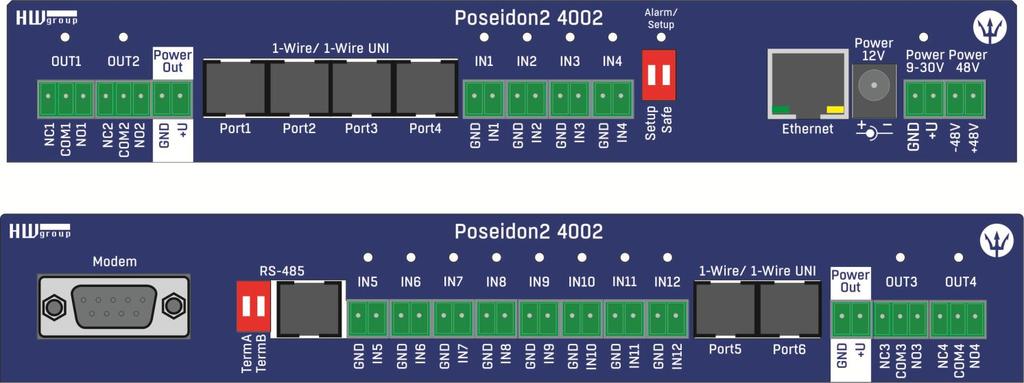
4 RELAY OUTPUTS Two 50V rated DT relay contacts POWER OUT 12V power output for sensors DIGITAL INPUTS Digital inputs 1 4 for dry contacts DIP switch Configuration switches Default is Off, Off ETHERNET 10 or 100/10 Mbps POWER input 9-30V supply SENSORS 1-Wire/1-Wire UNI Port1 to Port4 for connecting 1-Wire and 1-Wire UNI sensors GSM MODEM RS-232 port to connect a modem DIGITAL INPUTS Inputs 5 12 for dry contacts OUTPUTS Two 50V rated DT relay contacts RS-485 Termination Activates termination of the RS-485 bus RS-485 bus For genuine HW group sensors Power Out Power output for a GSM modem or detectors 4
, RJ-45 port. Plug the power adapter into a mains outlet and connect it to the Poseidon power jack.")
5 First steps 1) Connecting the cables Turn the unit and note its MAC address that is printed on the label on the side. Set the switches: DIP1=Off, DIP2=Off. Connect Poseidon to Ethernet (patch cable to a switch, cross-over cable to a PC), RJ-45 port. Plug the power adapter into a mains outlet and connect it to the Poseidon power jack. The green POWER LED lights up. If the Ethernet connection works properly, the LINK LED lights up after a short while, and then flashes whenever data are transferred (activity indication). 2) Configuring the IP address UDP Config UDP Config utility root directory of the supplied CD (Windows and Linux versions). Available for download at Software > UDP Config. Click the icon to launch UDP Config. The program automatically looks for connected devices. Automatic device discovery works only in the local network. Individual Poseidon units are identified by their MAC addresses (on the label at the bottom). Double-click a MAC address to open a basic device configuration dialog. Double click for details 5

6 First steps Configure the network parameters IP address / HTTP port (80 by default) Network mask Gateway IP address for your network Device name (optional) Click the Apply Changes button to save the settings. Alternatively, you may use the following utilities to configure the IP address: UDP Config for Linux Important: To reset the device to factory defaults, toggle DIP1 several times within 5 seconds after applying power to the device. No configuration changes can be stored while DIP2=On. To change the IP address, set DIP2=Off. 6
 SNMP: SNMP / SNMP Trap")


7 First steps 4) WWW interface of the device To open the WWW interface of the device: o Enter the IP address into a web browser o Click the IP address in UDP Setup Web interface of the device General: Overview of current readings General Setup: IP address, DNS, security (username/password) SNMP: SNMP / SNMP Trap configuration (ports and alarm recipients) server, parameters, recipients, test GSM: Local GSM modem / remote SMS-GW configuration Log & Time: Time configuration, NTP server Portal: Connection to a remote portal system Sensors: Device name, sensor names, status overview Inputs: Digital Input control, names, alarm parameters Outputs: Digital Output control, names, local mode System: Firmware upgrade, save/restore configuration, etc. DIP2 = ON Configuration cannot be changed over the network User-defined names for digital inputs and outputs Alarm thresholds Action when value out of range MIB file for SNMP software 7


8 General Setup Device name, e.g. First floor 1 Three levels of passwords for device security. SNMP 5 destinations for SNMP Traps 8
.")
9 Inserts this text at the beginning of the subject line Up to 5 recipients for alarm s Sends a test and shows the connection log test result Periodic Status Settings Periodical Status When on, sends an with device status at the specified intervals. For example every 24 hours (1440 minutes). Alarm reminder When active, sends periodic reminders that the device is in the Alarm state. For example every 15 minutes. To send , check: 1) Correct Gateway IP address 2) DNS server in network settings 3) SMTP server and port 4) Authentication turned on, correct username and password 5) Spam filter for your mailbox is disabled NOTE: Configuration changes must be confirmed by clicking the Apply Changes button. 9
 Recipients' phone no's Log & Time Press")

10 GSM To send text messages using a local GSM modem (RS-232), select GSM modem and set GSM function to Local. IP address of HWg-SMS-GW to use for sending text messages (SMS) Recipients' phone no's Log & Time Press the button to synchronize time Interval for logging measured values Expected size of recorded data Frequency of sending the log file in attachments Opens the log file in the browser as text 10

11 Portal Message from the portal Enable connection to the remote portal Click to connect to the portal AutoPush configuration We recommend 2 C for temperature and 5%RH for humidity. Configures the communication with the portal using the HWg-Push protocol. Poseidon2 is the active side and establishes the connection periodically and/or whenever a change in a sensor value exceeds the configured AutoPush value. The portal connection parameters are pre-filled. AutoPush configuration Poseidon2 connects to the portal and notifies a value change whenever a change in the sensor reading exceeds the configured AutoPush value. This configuration only applies to the communication between Poseidon2 and the online portal. Local alarm values are configured in the portal. For portal connection, check: 1) Correct Gateway IP address 2) DNS server in network settings 3) Correct Server Address of the portal 11
 if the Safe Range for this sensor is exceeded")
 whenever the reading fluctuates around the threshold, you can use: 1) Hysteresis Idle Range Tolerance band around the Safe Range.")
12 Sensors Range of allowed values. If exceeded, alarm is signaled. Sends a SNMP trap if the Safe Range for this sensor is exceeded Sends an if the Safe Range for this sensor is exceeded Sends a text message (SMS) if the Safe Range for this sensor is exceeded Sensor name will be shown in s, text messages, or SNMP traps Scans connected sensors and displays detected After connecting sensors or changing RJ11 connections, sensors need to be detected again. To avoid numerous false alerts (by or SMS) whenever the reading fluctuates around the threshold, you can use: 1) Hysteresis Idle Range Tolerance band around the Safe Range. Prevents multiple alarm alerts. 2) Delay [s] Delays the information about alarm beginning and alarm end by a specified time. Can be used for dry contacts, too. Tip: For details, see the complete Poseidon2 family manual. NOTE: Configuration changes must be confirmed by clicking the Apply Changes button. 12
 Disabled No Alarm Reaction to digital inputs: Disabled Send a SNMP Trap Send an E-mail Send a SMS Connecting the inputs FAQ 0 (Off) 1 (On) Poseidon2 informs about alarm activation and")
13 Inputs Enter Digital Input name, will be shown in s, text messages or SNMP traps ALARM CONTACT STATUS: Active if On Alarm when the contact closes (1 = On) Active if Off Alarm when the contact opens (0 = Off) Disabled No Alarm Reaction to digital inputs: Disabled Send a SNMP Trap Send an Send a SMS Connecting the inputs FAQ 0 (Off) 1 (On) Poseidon2 informs about alarm activation and deactivation for each Digital Input and/or sensor. format cannot be changed; sensors may have custom names. Yellow background in a line with a sensor or an input means that the safe range is exceeded but alarm notification is off. TIP Poseidon family manual For a detailed description of all settings and configuration tabs, see the Poseidon family manual on the WEB or on the installation CD. 13
14 14

15 Outputs Choose the output mode Local Condition mode: Manual mode: Controls the outtput according to the specified sensor Output controlled over the WEB or M2M protocols Output mode: A) Manual Output can be controlled using the Web interface or externally using M2M protocols. The output cannot be used in thermostat mode local condition. B) Local Condition The output cannot be controlled over the Web, it is controlled by the local condition. The output is read-only for all M2M protocols. Hysteresis in the sensor settings applies. The output cannot be controlled remotely. o o o o o On if any alarm The output is active if at least one input or sensor is in alarm. On if value equal to Trigger The output is active if the selected sensor reading is equal to the Target Value. On if value higher than Trigger The output is active if the selected sensor reading is greater than the Target Value. On if value lower than Trigger The output is active if the selected sensor reading is less than the Target Value. Dependent On sensor / input to which the condition applies. 15

16 System Protocols and timeout for the communication monitor Loads the configuration XML file to Poseidon2 from the PC Uploads new firmware from the PC Configuration Download Retrieve the configuration from the device and store it on the PC. Upload Restore a configuration from the PC to the device. System Restart Device Reset the device over the WEB interface. Communication Monitor This function controls a virtual Digital Input that is available in Inputs as Com Monitor 1 with an ID of 123. If no communication took place in the specified time using the selected protocols, it sets Com Monitor 1 = 0 (Off). This function is useful e.g. to send a warning whenever Poseidon2 ceases to be periodically monitored over SNMP or SCADA. Set Default Config Restore factory-default settings. Upgrade FW Upload new firmware to the device. NOTE: Configuration changes must be confirmed by clicking the Apply Changes button. 16
. Data are retrieved from the device over http or e-mail.")

 using HWg-SMS-GW.")
17 Software Applications HWg-PDMS Windows application that logs data from all devices into its internal database. The application runs in the background (NTservice). Data are retrieved from the device over http or . Data can be exported over XML or automatically stored to MS Excel. License: Free HWg-PDMS version for 3 sensors Paid versions for 8 / 20 / 200 / unlimited sensors HWg-Trigger Windows application for detecting and reacting to events. Detects, for instance, disconnected devices, failed sensors values out of range, or incoming SNMP Trap alerts. Possible responses include sending an , activating a relay over the network, or sending a text message (SMS) using HWg-SMS-GW. Other responses include displaying a warning message in Windows, starting an application, or shutting down the computer. License: 30-day trial version free of charge 17


18 PosDamIO Poseidon Damocles I/O is a command-line utility for Windows and Linux that lets you control Poseidon and Damocles units over the XML interface. It can display the states of sensors, inputs and outputs, as well as set an output high or low. SensDesk.com Online portal for collecting data from LAN and GSM sensors. Poseidon2 can connect to the SensDesk internet service. All devices can be managed from a single WWW interface. Watch sensor states, display your devices in a map, compare trends in time and analyze alarm messages. SensDesk is a way to implement fully functional monitoring of customer technology in a matter of minutes, with fixed costs of the system. No need for installing a complex system or adding another server at the customer side. Overview of all sensors at a single place Centralized alarm configuration for individual sensors Mobile application for monitoring Remote configuration of GSM devices
19 Specifications OVERVIEW LAN interface Supported protocols SNMP compatibility Internal Logger SENSORS 1-Wire Type Active ports / distance Sensors SENSORS RS-485 Type Connector / distance Sensors RJ45 (100BASE-Tx) 10/100 Mbps network compatible IP: ARP, TCP/IP (HTTP, NTP, SMTP, netgsm, HWg-PUSH), UDP/IP (SNMP) Ver.1.00 compatible, partial ver.2.0 implementation 250,000 records in flash memory (logged items: Sensors, DI, DO) original accessories: 1-Wire & 1-Wire UNI 6xRJ11, max distance 60m per each RJ11 active port Up to 16 sensors in total (temperature + humidity combo sensors count as 2 sensors) HWg original accessories RJ45 + 2x DIP for termination / Max distance 1000m Up to 26 sensors in total (temperature + humidity combo sensors count as 2 sensors) DI (Digital Inputs for Dry Contacts) Port / type IN1-IN12 / Digital Input (supports NO/NC Dry contact) Sensitivity 1 (On) = Ω (Max. distance up to 50m) DO - OUTPUTS Port / type Max. voltage / load State RS-232 interface External GSM modem POWER input Port Power input POWER output Voltage Current / Connector LED status indicators POWER (RJ45 + top) LINK & Activity (RJ45) Setup / Alarm Inputs / Outputs DIP SWITCH DIP1: Setup DIP2: Security OUT1 - OUT4 / Relay contacts (NC-COM-NO) 60V AC/DC, Max 1A, up to 60VA/24W ( 0.5A/48V) Power up state (no state restart memory) Connect external GSM modem POWER 9-30V DC 9-30V DC / 2,5W (typically 250 ma) Connectors: Jack (barrel, inner 2.1 mm outer 5.1 mm) + Terminal Block Power Out = Power IN (9 30V) Max. 150mA / Terminal Block Green power OK (top), Ethernet enabled (RJ45) Yellow - Ethernet connectivity Red Green / Yellow OFF = Normal state Load defaults: Set ON, power-up device, toggle 3 times during first 5 seconds ON = Secure mode (online demo) remote configuration disabled OFF = Non-secure mode remote configuration enabled Physical parameters Temperature range Operating: -30 to +85 C (-22 to +185 F) / Storage: -35 to +85 C (-31 to +185 F) Dimensions / Weigh 100 x 213 x 35 [mm] / 225 g EMC FCC Part 15, Class B, CE - EN 55022, EN 55024, EN
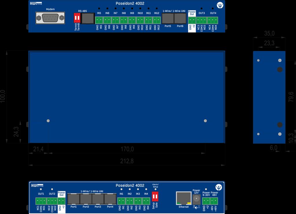

20 Dimensions 20
 state, or device turned off When the output is On (1), a Normally Open (NO) relay contact is closed LEDs: Contact state")
21 Power output Poseidon features the PWR OUT terminals for powering connected sensors and detectors. For example a smoke detector. PWR OUT voltage is the same as the Poseidon supply voltage! Relay outputs NO COM NO NC POWER OUT 12V + - NO and NC labels apply to Off (0) state, or device turned off When the output is On (1), a Normally Open (NO) relay contact is closed LEDs: Contact state (closed / open) is indicated by a LED Isolation: The double-throw contact is electrically isolated from the rest of the device ID range: Outputs use ID addresses from 151 to 180 Inputs Digital (dry contact) inputs Digital input terminals may be connected to voltage-free contacts or the GND pin. The inputs are electrically connected to the 12V power supply. Never connect the inputs to the 48V supply voltage! Unconnected inputs read as 0 (Off) Active inputs read as 1 (On) Supported sensors: Any contact without external voltage (dry contact) Polling period: 800 ms Range of sensor IDs: Inputs use ID addresses from 1 to
, see the detailed Poseidon family manual.")
22 M2M interface The product is ready to be connected with third-party SW applications. For a description of the interfaces (XML format, detailed SNMP description, mapping of Modbus/TCP variables), see the detailed Poseidon family manual. XML (over HTTP) SNMP, SNMP traps Modbus/TCP SMTP ( ) TIP For a detailed description of the M2M communication interface and other details, see the detailed Poseidon family manual. SDK (Software Development Kit) Programmers can take advantage of the HWg SDK (Software Development Kit) with ActiveX interface and ready-made examples. VB - Visual Basic (6.0) - (3xx examples) Borland C++ (1xx examples) Microsoft Visual C++ (2xx examples) C# /.NET (5xx examples) Borland Delphi (4xx examples) JAVA PHP / ASP other examples that do not directly use SDK functions (all 9xx examples) Note: The latest version of HWg-SDK is available for download at the HWg website. You just need to register your

23 Updating the firmware over the WEB Upload the.hwg firmware file over http to Connection problems must be avoided during file transfer. Firmware in the.hwg format is available at our website, or on the supplied CD. Restoring factory defaults To restore the factory default configuration (including deleting all passwords): 1) Turn the device off by disconnecting power. 2) Set DIP1 to ON. 3) Turn the device on. 4) Toggle DIP1 several times during the first 5 seconds after powering up. TIP For a detailed product description, see the detailed Poseidon family manual. 23
24 24

25 Mounting on a wall Mounting on a DIN rail Contact s.r.o Rumunská 26 / 122 Praha 2, , Czech republic Tel Fax
Poseidon MANUAL
 Poseidon2 3266 MANUAL Safety information The device complies with regulations and industrial standards in force in the Czech Republic and the European Union. The device has been tested and is supplied
Poseidon 4002 MANUAL
 Poseidon 4002 MANUAL Poseidon 4002 MANUAL POWER input 12VDC supply (jack or terminals) INPUTS Binary inputs 1 6 (for contacts) OUTPUTS Two 50V rated switchover relay contacts ETHERNET 10 or 100/10 Mbps
Connector for sensing cable
 HWg-WLD MANUAL ETHERNET 10/100 Mbps Status LED Yellow: Power & Mode Green: Link & Activity Connection cable 100 m max POWER input 5V DC supply Use the supplied power adapter SENSOR Connector for sensing
HWg-STE HWg-STE PoE MANUAL
 HWg-STE HWg-STE PoE MANUAL HWg-STE connections LED indicators Green: Power & Mode Yellow: Link & Activity SENSORS S1 and S2 ports for connecting temperature or humidity sensors. - Max. distance with 1
Damocles2 User guide
 User guide family Table of contents is a family of products for remote monitoring and control of a LAN. The family consists of several versions designed for different uses (19 cabinets, data centers, electric
HWg-SMS-GW manual. HW group. HWg-SMS-GW. SMS gateway for HW group products. 1
 HWg-SMS-GW SMS gateway for products www.hw-group.com 1 Recommended connection HWg-SMS-GW is a device that enables multiple devices to send alarm text messages (SMS) through a single GSM modem using the
Poseidon 2250 Short Manual
 Poseidon 2250 Short Manual www.hw-group.com 1 / 54 Safety information The device complies with regulations and industrial standards in force in the Czech Republic and the European Union. The device has
proudly presents HW group Environment Monitoring Systems
 Sumpftrasse 32 6300 Zug Switzerland www.temperatur-sensor.ch proudly presents HW group Environment Monitoring Systems Jens Albrecht, B.S. EE CEO About HW group s.r.o company HW group produces IP sensors
Industrial Serial Device Server
 1. Quick Start Guide This quick start guide describes how to install and use the Industrial Serial Device Server. Capable of operating at temperature extremes of -10 C to +60 C, this is the Serial Device
TCD channel H.264 Video Encoder Hardware User s Manual (DC 12V) Ver. 2010/10/29
 Ver. 2010/10/29") TCD-2100 1-channel H.264 Video Encoder Hardware User s Manual (DC 12V) Ver. 2010/10/29 Table of Contents 0. Precautions 3 1. Introduction 4 Package Contents... 4 Features and Benefits... 5 Safety Instructions...
TCD-2100 1-channel H.264 Video Encoder Hardware User s Manual (DC 12V) Ver. 2010/10/29 Table of Contents 0. Precautions 3 1. Introduction 4 Package Contents... 4 Features and Benefits... 5 Safety Instructions...
IP Sensor IPS2222 User manual
 IP Sensor IPS2222 User manual Output LED indicators Power input 12VDC adapter 2 Relay outputs LED Indicators 1 wire 2 Dry 2 Analog Green : Power Yellow: Link temperature & humidity contact inputs inputs
PCE-IMS 1 User Manual IP Monitoring systems IP Switchable Metered PDU s
 PCE-IMS 1 IP Monitoring systems IP Switchable Metered PDU s System installation System setting Accessories Monitoring master unit Extension units Sensors SNMP server List of USB-cameras - 02 - Contents
Installation of the PCMeasure Movement Sensor (30114)
") 1. Hardware: Installation of the PCMeasure Movement Sensor (30114) Connect the sensor to a serial or parallel port of the PC using one of the PCMeasure adaptors, or directly to the PCMeasure Ethernet Box.
1. Hardware: Installation of the PCMeasure Movement Sensor (30114) Connect the sensor to a serial or parallel port of the PC using one of the PCMeasure adaptors, or directly to the PCMeasure Ethernet Box.
Application. Contents of Package. Inspect the CyberSwitch upon receipt. The package should contain the following items:
 Overview CyberPower power manager CyberSwitch is the ultimate power control center to manage multiple network devices via the Internet. After installing the hardware and setting up an IP address, this
TCD channel H.264 Video Encoder with WDR (DC 12V) Ver. 2012/6/25
 Ver. 2012/6/25") TCD-2500 1-channel H.264 Video Encoder with WDR (DC 12V) Ver. 2012/6/25 Table of Contents 0. Precautions 3 1. Introduction 4 Package Contents... 4 Features and Benefits... 5 Safety Instructions... 7 Physical
TCD-2500 1-channel H.264 Video Encoder with WDR (DC 12V) Ver. 2012/6/25 Table of Contents 0. Precautions 3 1. Introduction 4 Package Contents... 4 Features and Benefits... 5 Safety Instructions... 7 Physical
SNMP Web Management. User s Manual
 SNMP Web Management User s Manual Suitable Product: SNMP Web Card SNMP Web Box Management Software for Uninterruptible Power Supply Systems Table of Contents 1. Overview... 1 1.1 Introduction... 1 1.2
HWg-PWR 3/12/25 MANUAL
 HWg-PWR 3/12/25 MANUAL Package contents A complete shipment contains the following items: HWg-PWR25 (HWg-PWR12) unit Printed manual + datasheet Safety information The device complies with regulations and
Safety information. Table of contents. Device housing cannot be opened if the relay contacts are connected to a power network.
 HWg-SH4 User guide Safety information The device complies with regulations and industrial standards followed in Czech Republic and European Union. The device has been tested and is supplied in working
Industrial Device Server IDS-3010 Fiber Series
 USER S MANUAL Industrial Device Server IDS-3010 Fiber Series Ver. 1.0, Jan. 2008 Table of Content Getting to Know Your Device Server... 3 1.1 About the IDS-3010 Serial Device Server... 3 1.2 Software Features...
ETHM-2. Ethernet Module. SATEL sp. z o.o. ul. Schuberta Gdańsk POLAND tel
 Ethernet Module ETHM-2 Firmware version 1.0 ethm2_en 09/08 SATEL sp. z o.o. ul. Schuberta 79 80-172 Gdańsk POLAND tel. + 48 58 320 94 00 info@satel.pl www.satel.pl SATEL's goal is to continually improve
User s Manual PowerPanel Shutdown Service Graceful Shutdown and Notification service to ensure power protection of your computer
 User s Manual PowerPanel Shutdown Service Graceful Shutdown and Notification service to ensure power protection of your computer Version 1.3 TABLE OF CONTENTS INTRODUCTION... 1 INSTALLATION GUIDE... 4
Encoder Firmware V User s Manual. Outdoor PTZ Camera Hardware Manual KCM /05/09.
 Encoder Firmware V4.06.09 User s Manual Outdoor PTZ Camera Hardware Manual KCM-8211 2013/05/09 1 Table of Contents Precautions... 3 Introduction... 4 List of Models... 4 Package Contents... 5 Safety Instructions...
INDEX. Network Power Monitor NPM-R10-SNMP. Innovative Electronics for a Changing World. NPM-R10-SNMP Remote Network Power Monitor
 Innovative Electronics for a Changing World NPM-R10-SNMP Remote Network Power Monitor Optional relay board and GSM module INDEX 1. SYSTEM DESCRIPTION 2. SYSTEM BATTERY CONNECTIONS 3. SERIES CONNECTED BATTERIES
NCOM SERIAL DEVICE SERVER 1XX SERIES USER S MANUAL
 NCOM SERIAL DEVICE SERVER 1XX SERIES USER S MANUAL 2017-07-07 Edition Titan Electronics Inc. Web: www.titan.tw Contents 1. INTRODUCTION... 4 1.1 Key Features... 5 1.2 Specifications... 6 2. PANEL LAYOUT
GV-AS200 Controller. Hardware Installation Guide
 GV-AS200 Controller Hardware Installation Guide Before attempting to connect or operate this product, please read these instructions carefully and save this manual for future use. 2008 GeoVision, Inc.
E12. 3MP Cube with Basic WDR, Fixed lens Hardware User s Manual. (PoE) Ver. 2012/10/22
 Ver. 2012/10/22") E12 3MP Cube with Basic WDR, Fixed lens Hardware User s Manual (PoE) Ver. 2012/10/22 Table of Contents 0. Precautions 3 1. Introduction 4 Package Contents... 4 Features and Benefits... 5 Safety Instructions...
E12 3MP Cube with Basic WDR, Fixed lens Hardware User s Manual (PoE) Ver. 2012/10/22 Table of Contents 0. Precautions 3 1. Introduction 4 Package Contents... 4 Features and Benefits... 5 Safety Instructions...
EGW1-IA3-MB User s Manual
 www.exemys.com Rev. 0 1 Products are in constant evolution to satisfy our customer needs. For that reason, the specifications and capabilities are subject to change without prior notice. Updated information
PN5212/PN5320/PN7212/PN7320
 PN522/PN520/PN722/PN720 Power Over the NET Power Distribution Units ALTUSEN Power Over the NET products are Power Distribution Units that offer outlet level control combined with remote access to give
Technical Manual Nova: Cabinet Security Management System (CSMS)
") Technical Manual Nova: Cabinet Security Management System (CSMS) KP_nova_TM_160501_EN 1 Publication May, 2016, Keyprocessor BV Paasheuvelweg 20 1105BJ Amsterdam, The Netherlands www.keyprocessor.com/nova
Technical Manual Nova: Cabinet Security Management System (CSMS) KP_nova_TM_160501_EN 1 Publication May, 2016, Keyprocessor BV Paasheuvelweg 20 1105BJ Amsterdam, The Netherlands www.keyprocessor.com/nova
User s Manual PowerPanel Shutdown Service Graceful Shutdown and Notification service to ensure power protection of your computer
 User s Manual PowerPanel Shutdown Service Graceful Shutdown and Notification service to ensure power protection of your computer K01-SNMP004-00 TABLE OF CONTENTS INTRODUCTION... 1 INSTALLATION GUIDE...
Features. :. Introduction. :. Leader 5000 Appearance. Ethernet-Based Block I/O System
 Features 10/100Mbps Ethernet full duplex Auto Negotiation Support C++/C Modbus/TCP drivers and OPC server Support configuration via built-in Web browsing, (HTML), Device Finder and I/O configuration utilities
The GV-I/O Box 16 Ports provides 16 inputs and 16 relay outputs, and supports both DC and AC output voltages.
 GV-I/O Box 16 Ports The GV-I/O Box 16 Ports provides 16 inputs and 16 relay outputs, and supports both DC and AC output voltages. Key Features 16 inputs and 16 outputs are provided. Up to 9 pieces of GV-I/O
Table of Contents. 1. Introduction Package Contents Function Installation Web Interface... 5
 User Manual Table of Contents 1. Introduction... 1 2. Package Contents... 2 3. Function... 3 4. Installation... 4 5. Web Interface... 5 6. Specifications... 8 1. Introduction The ServerLink PDU is a network
VENTEV INNOVATIONS BTRM200 Battery Test Remote Monitoring System User Guide V1.0. Innovations BTRM200. Battery Test Remote Monitor User Guide
 Innovations BTRM200 Battery Test Remote Monitor User Guide Contact : Ventev Innovations 10999 McCormick Road Hunt Valley, MD 21031 Phone Number 800.759.9996 Email Info@ventev.com 1 Contents 1. 2. 3. 4.
B-33. Hardware and Install Manual. (DC 12V / PoE)
") B-33 Hardware and Install Manual (DC 12V / PoE) Table of Contents Precautions 3 Safety Instructions... 4 Introduction 6 Package Contents... 6 Physical Description... 7 Installation Procedures 9 Step 1:
B-33 Hardware and Install Manual (DC 12V / PoE) Table of Contents Precautions 3 Safety Instructions... 4 Introduction 6 Package Contents... 6 Physical Description... 7 Installation Procedures 9 Step 1:
TCM H.264 Megapixel IP PoE Cube Camera Hardware User s Manual. (PoE) Ver. 2011/11/30
 Ver. 2011/11/30") TCM-4511 H.264 Megapixel IP PoE Cube Camera Hardware User s Manual (PoE) Ver. 2011/11/30 Table of Contents 0. Precautions 3 1. Introduction 4 Package Contents... 4 Features and Benefits... 5 Safety Instructions...
TCM-4511 H.264 Megapixel IP PoE Cube Camera Hardware User s Manual (PoE) Ver. 2011/11/30 Table of Contents 0. Precautions 3 1. Introduction 4 Package Contents... 4 Features and Benefits... 5 Safety Instructions...
DT Desktop Series
 5600-8-DT Desktop Series Compact 8-port Serial s Features 8 ports supporting RS-232, RS-422, or RS-485 operation Compact desktop size Auto-detecting 10/ 100 Mbps Ethernet 15 KV ESD surge protection for
Table Of Contents. 1. Introduction... 1
 User Manual Table of Content Table Of Contents 1. Introduction... 1 1.1 Brief Introduction to Web Interfaces... 1 1.2 How to Log In... 1 1.3 General Setting... 2 1.3.1 Date and Time Setting... 2 1.3.2
Network Management Card. User Manual
 User Manual 1 Contents Contents 2 Chapter 1 Overview 3 1.1 NMC package contents 4 1.2 NMC CD Resources 4 1.3 Features 4 1.4 NMC Applications 5 Chapter 2 NMC parameters setting via serial COM port 6 2.1
1-channel MPEG-4 Video Encoder ACD-2100T. Ver User s Manual 0-0
 1-channel MPEG-4 Video Encoder ACD-2100T Ver. 080619+ User s Manual 0-0 0 0 PRECAUTIONS 1. Read these instructions All the safety and operating instructions should be read before the product is operated.
Lantech LSC-1102B SERIAL TO TCPIP CONVERTER. User Manual
 Lantech LSC-1102B SERIAL TO TCPIP CONVERTER User Manual V1.0 Sep 2016 Table of Contents 1. Introduction 3 Overview 4 Product Specifications 8 2. Description & Installation 10 Product Panel Views 10 LED
sensorprobe2 / sensorprobe8 User Manual
 www.akcp.com sensorprobe2 / sensorprobe8 User Manual Help Version updated till firmware 382L Copyright 2007, AKCP Co., Ltd.. 1) Introduction 1. What is sensorprobe? 2. What s the difference between sp2
EP2 EP8 User Manual. Copyright 2007,ATAL
 EP2 EP8 User Manual Copyright 2007,ATAL 1) Introduction 1. What is EP? 2. What s the difference between the EP2 and the EP8? 3. How to use this manual 4. EP2 5. EP8 2) Installation 1. Assigning an IP address
1. Short description. 2. Features. 3. Technical parameters
 1. Short description TCW122B-RR is a remote relay control module with embedded WEB server for set up. The device has two digital inputs and two relays, with normally open and normally closed contacts.
User Manual PDUTracker
 User Manual PDUTracker Management Software for PDU Table of Contents 1. Overview... 1 1.1. Introduction... 1 1.2. Features... 1 2. Install and Uninstall... 1 2.1. System Requirement... 1 2.2. Software
MGate 5102-PBM-PN Series
 MGate 5102-PBM-PN Series 1-port PROFIBUS-to-PROFINET gateways Features and Benefits Protocol conversion between PROFIBUS and PROFINET Supports PROFINET IO device Supports PROFIBUS DP V1 master Automatic
Features and Benefits. SNMP MIB-II for network management. Certifications
 NPort 5600-DT Series 8-port RS-232/422/485 serial device servers Features and Benefits 8 serial ports supporting RS-232/422/485 Compact desktop design 10/100M auto-sensing Ethernet Easy IP address configuration
INDEX. Network Power Monitor R10 SNMP
 Innovative Electronics for a Changing World NPM-R10 Remote Network Power Monitor With optional relay board and GSM module INDEX Amended 21 March 2017: Add user defined Password see page 13 Add wire Connection
ILF-100WD User Manual. Router Watchdog / Connection Monitor 2007 Stealth Laboratories, LLC Patent Pending
 ILF-100WD User Manual Router Watchdog / Connection Monitor 2007 Stealth Laboratories, LLC Patent Pending Rev. 1.17 02/24/2009 Table of Contents Installation and Configuration...3 Network Configuration...4
Network Management Card. User Manual
 User Manual 1 Contents Contents 2 Chapter 1 Overview 3 1.1 NMC package contents 4 1.2 NMC CD Resources 4 1.3 Features 4 1.4 NMC Applications 5 Chapter 2 NMC parameters setting via serial COM port 6 2.1
REFERENCE GUIDE. Copyright ComAp s.r.o.
 IB-Lite Plug-in Ethernet module To be used with ComAp controllers: IL MRSXX, IL AMFXX, IL-NT MRSXX, IL-NT AMFXX, IC-NT SPtM, IC-NT MINT, MC-NT, ID-Lite and other controllers based on these platforms SW
BTRM200 Battery Test Remote Monitor. User Guide
 BTRM200 Battery Test Remote Monitor User Guide Contact : Ventev Wireless Infrastructure 11126 McCormick Road Hunt Valley, MD 21031 Phone Number 800.851.4965 Email Sales@ventev.com Ventev Wireless Infrastructure
OnCell G3100 Series Quick Installation Guide
 OnCell G3100 Series Quick Installation Guide Edition 4.1, August 2016 Technical Support Contact Information www.moxa.com/support Moxa Americas: Toll-free: 1-888-669-2872 Tel: 1-714-528-6777 Fax: 1-714-528-6778
User s Manual. Management Converter Chassis. Model No.: SP1386 / SP1387. World Wide Web: ;
 User s Manual Management Converter Chassis Model No.: SP1386 / SP1387 World Wide Web: www.micronet.com.tw ; www.micronet.info Table of Content 1. INTRODUCTION... 2 1.1 PACKAGE CONTENT... 2 1.2 KEY FEATURES...
ECO PDU Power Distribution Unit
 ECO PDU Distribution Unit PE6108/PE6208/PE8108/PE8208 ATEN has developed a new generation of green energy power distribution units (PDUs) to effectively increase the efficiency of data center power usage.
User Manual A08. User Manual
 A08 TABLE OF CONTENTS TABLE OF CONTENTS... 1 1. INTRODUCTION... 2 1.1. Key Features... 3 1.2. OS Requirement... 4 1.3. Specification... 4 1.4. Packing List... 4 2. OVERVIEW... 5 2.1. LED Definition...
NCOM SERIAL DEVICE SERVER 4XX SERIES USER S MANUAL
 NCOM SERIAL DEVICE SERVER 4XX SERIES USER S MANUAL 2017-07-07 Edition Titan Electronics Inc. Web: www.titan.tw Contents 1. INTRODUCTION... 4 1.1 Key Features... 5 1.2 Specifications... 6 2. PANEL LAYOUT
I/O ETHERNET CONTROLLER ELAN1
 I/O ETHERNET CONTROLLER ELAN1 Manual v1.0 Safety instructions Please read and follow these safety guidelines in order to maintain safety of operators and people around: Don t use the system in hazardous
Switched XPDU. 15A Model. User & Installation Manual Xtreme Power Conversion Corporation. All rights reserved.
 Switched XPDU 15A Model User & Installation Manual www.xpcc.com 2014. All rights reserved. (Rev 10/02/14) Table of Contents Introduction...4 PDU Package...4 Function...4 Interface...4 Installation...5
Operation Manual of EX9132CST-Series
 Operation of EX9132CST-Series Serial to TCP/IP Converter (EX9132CST-2/ EX9132CST-RS485/ EX9132C-RS232) Version 1.0.0. 30.03.2017 Table of Contents 1 Introduction... 4 2 Overview... 5 2. 1 Package Checklist...
3. Technical parameters
 1. Short description TCW181B-CM is 8-channel Ethernet relay board, which is designed to work in IP-based networks and managed by WEB interface or SNMP programs. The device can be used stand-alone or as
Encoder Firmware V User s Manual. Outdoor PTZ Camera Hardware Manual KCM /05/28
 Encoder Firmware V4.06.09 User s Manual Outdoor PTZ Camera Hardware Manual KCM-8211 2013/05/28 Table of Contents Precautions... 3 Safety Instructions... 5 Introduction... 6 List of Models... 6 Package
Innovative Electronics for a Changing World INDEX
 Innovative Electronics for a Changing World INDEX 1. SYSTEM DESCRIPTION 2. BOARD CONNECTIONS terminals and indicators 3. CONNECTION DIAGRAM 4. START UP GUIDE and passwords 5. HOME PAGE 6. STATUS PAGE 7.
NET101. RS232 / RS422 / RS485 to Ethernet Converter. User s Manual. Version 1.2
 NET101 RS232 / RS422 / RS485 to Ethernet Converter User s Manual Version 1.2 Copyright Information Copyright 2004-2005, Mega System Technologies, Inc. All rights reserved. Reproduction without permission
SR-201 Network Relay Quick Start Guide
 SR-201 Network Relay Quick Start Guide Table of Content Connect to your device...2 Change configurations...3 Setup remote control via internet...4 Android software...5 Integrate to your applications...6
VT805 / Monitoring system
 Environmental Infrastructure monitoring VT805 / Monitoring system Environmental monitoring of any facilities, control of security breaches, temperatures, smoke, water leakages, voltages and more. Compatible
USER S MANUAL. PH485Ex1. #1 RS-485 Serial Port to Ethernet, Terminal Server/Client. Doc No: PH485Ex1-UM-001 IPEX. (IP Electronix)
") USER S MANUAL PH485Ex1 Doc No: PH485Ex1-UM-001 #1 RS-485 Serial Port to Ethernet, Terminal Server/Client IPEX (IP Electronix) Contents 1. INTRODUCTION... 3 2. SPECIFICATIONS... 3 3. PACKAGE CHECKLIST...
USER S MANUAL PH485Ex1 Doc No: PH485Ex1-UM-001 #1 RS-485 Serial Port to Ethernet, Terminal Server/Client IPEX (IP Electronix) Contents 1. INTRODUCTION... 3 2. SPECIFICATIONS... 3 3. PACKAGE CHECKLIST...
Features and Benefits. User-friendly LCD panel for easy installation Adjustable termination and pull high/low resistors.
 NPort 5400 Series 4-port RS-232/422/485 serial device servers Features and Benefits User-friendly LCD panel for easy installation Adjustable termination and pull high/low resistors Socket modes: TCP server,
IN-E1004 Encoder Hardware Manual
 IN-E1004 Encoder Hardware Manual 2014/06/03 Table of Contents Precautions... 4 Safety Instructions... 6 Introduction... 7 The List of Models... 7 Package Contents... 8 Physical Description... 9 Mounting
ROOM GUARD VT335. Environmental Infrastructure monitoring
 Environmental Infrastructure monitoring ROOM GUARD VT335 Environmental monitoring of any facilities, control of security breaches, temperatures, smoke, water leakages, voltages and more. Compatible with
GV-IP Decoder Box Plus User s Manual
 GV-IP Decoder Box Plus User s Manual Before attempting to connect or operate this product, please read these instructions carefully and save this manual for future use. DBPV10-UM-A 2015 GeoVision, Inc.
HWg-Tg11 First steps for remote monitoring & logging via GSM/GPRS
 HWg-Tg11 Manual HWg-Tg11 First steps for remote monitoring & logging via GSM/GPRS Device description Power supply connector - RJ12 connector Device status indicators Red, Green, Yellow indicators Antenna
Dupline. Data Logger. Types G , G Product Description. Ordering Key G Type Selection. Input/Output Specifications
 Dupline Data Logger Types G 800 006, G 800 106 Product Description Programmable channel generator with optional built-in GSM Modem Event and time based data logging functions for digital, analog and counter
1111 West 35th Street Chicago, IL Customer Support: (773) UPS SNMPWEBCARD
 UPS SNMPWEBCARD") 1111 West 35th Street Chicago, IL 60609 Customer Support: (773) 869-1234 www.tripplite.com UPS SNMPWEBCARD USER S GUIDE FCC Radio/TV Interference Notice The SNMPWEBCARD has been tested and found to comply
1111 West 35th Street Chicago, IL 60609 Customer Support: (773) 869-1234 www.tripplite.com UPS SNMPWEBCARD USER S GUIDE FCC Radio/TV Interference Notice The SNMPWEBCARD has been tested and found to comply
TEMPERATURE AND ENVIRONMENT MONITORING MONITORE * CONTROL * ALERT * RECORD * ANALYZE
 TEMPERATURE AND ENVIRONMENT MONITORING MONITORE * CONTROL * ALERT * RECORD * ANALYZE A Solution for every need and every budget Offers built-in temperature and humidity sensors and allows external detectors
LAN Interface TCW120B
 LAN Interface TCW120B 1. Short description TCW120 is a multifunctional device for remote monitoring and management. It is an Ethernet based controller, which is designed to work in IP-based networks and
Power Switch Cabinet 4-Port New Generation
 May 2011 PSE544-XX Power Switch Cabinet 4-Port New Generation SUPPORT FREE technical support This product carries the CE mark to indicate compliance with the European Directive on Electromagnetic Compatibility
TRP-C34H. Ethernet to 4 RS232/422/485 Converter. User s Manual. Printed Sep Rev 1.1
 TRP-C34H Ethernet to 4 RS232/422/485 Converter User s Manual Printed Sep. 2013 Rev 1.1 Trycom Technology Co., Ltd 1F, No.2-11, Sihu street, Yingge Township, Taipei, Taiwan ROC Tel: 886-2-86781191, Fax:
MGate 5118 Quick Installation Guide
 MGate 5118 Quick Installation Guide Edition 1.0, December 2016 Technical Support Contact Information www.moxa.com/support Moxa Americas: Toll-free: 1-888-669-2872 Tel: 1-714-528-6777 Fax: 1-714-528-6778
Contents. GV-I/O Box 8 Ports Key Features Compatible Software Packing List Overview DIP Switch...
 Contents GV-I/O Box 8 Ports...2 1. Key Features... 2 2. Compatible Software... 2 3. Packing List... 2 4. Overview... 3 5. DIP Switch... 3 6. Connections to PC... 4 6.1 Installing USB Driver... 5 6.2 Assigning
A1000 GSM ALARM DEVICE
 A1000 GSM ALARM DEVICE USER MANUAL A1000-REV2.1-1604 FW-A1000v2.93 ERBAŞ TEKNOLOJİ Innovative Solutions 1 www.erbasteknoloji.com SAFETY INSTRUCTIONS - This user manual contains important notices for installation,
iologik E2200 Series Smart Ethernet remote I/O with Click&GO Logic Introduction Remote I/O PC-Free Alarm and Control Intelligence
 iologik E2200 Series Smart Ethernet remote I/O with Click&GO Logic Active communication with patented MX-AOPC UA Server and Active OPC server Smart alarm management with email, SNMP traps, TCP, UDP Save
256 MB RAM. 256 MB 32 bits RISC Cortex-A8 600MHz SD Card Slot. N/A USB Host. N/A USB Client
 User Manual V1.0.0 Table of Contents Overview... 1 1.1. Specification... 1 1.2. Dimensions... 2 1.3. Connector pinouts... 3 1.4. Restoring factory default... 3 1.5. LED indicator... 3 1.6. CR1225 battery...
MGate 5111 Quick Installation Guide
 MGate 5111 Quick Installation Guide Edition 1.0, December 2017 Technical Support Contact Information www.moxa.com/support Moxa Americas: Toll-free: 1-888-669-2872 Tel: 1-714-528-6777 Fax: 1-714-528-6778
MOXA VPort 2110/2140/2141 Video Server Quick Installation Guide
 MOXA VPort 2110/2140/2141 Video Server Quick Installation Guide Third Edition, July 2006 MOXA Networking Co., Ltd. Tel: +886-2-2910-1230 Fax: +886-2-2910-1231 www.moxa.com support@moxanet.com (Worldwide)
User Manual. Per Port Monitoring Models
 User Manual Per Port Monitoring Models Table of Contents 1. Introduction... 1 2. Package Contents... 2 3. Function... 3 4. Installation... 5 5. Web Interface... 6 1. Introduction The ServerLink Per Port
Canlan INSTALLATION MANUAL
 Canlan INSTALLATION MANUAL August 2014 Table of Contents Introduction... 4 Overview... 5 RJ45 Connector and Status LEDs... 5 Power Input... 6 RS232 / RS485 Connectors... 7 Installing the Canlan Software...
Motortronics VirtualSCADA VS2-MT Communication Gateway VS2-MT User Manual Revision
 Motortronics VirtualSCADA VS2-MT Communication Gateway VS2-MT User Manual Revision 1.03.00 Motortronics / Phasetronics 1600 Sunshine Drive Clearwater, Florida 33765 Tel: 727-573-1819 Fax: 727-573-1803
iomirror E3210 User s Manual
 User s Manual Edition 3.3, June 2017 www.moxa.com/product 2017 Moxa Inc. All rights reserved. User s Manual The software described in this manual is furnished under a license agreement and may be used
Communication adapter RS485/422 over the Ethernet ELO E222. User manual
 Communication adapter RS485/422 over the Ethernet ELO E222 User manual Table Of Content: 1.0 Introduction... 3 1.1 Application... 3 2.0 How does it works?... 4 3.0 Installation... 4 3.1 Ethernet connection...
Ethernet Environmental Monitoring Unit USER MANUAL
 Ethernet Environmental Monitoring Unit USER MANUAL 5019.xxxxx.00, Rev. 2.6 www.jacarta.com T. +44 (0) 1672 511125 Email: support@jacarta.com interseptor All trademarks belong to their respective proprietors.
Industrial Device Server User s Manual
 Industrial Device Server User s Manual IDS-5042 Series Version 1.00 Aug 2010. ORing Industrial Networking Corp. 4F., NO.3, Lane235, Baociao Rd.Sindian City, Taipei County 23145 Taiwan, R.O.C. Tel: + 886
Serial to Ethernet Converter
 Serial to Ethernet Converter User s Manual Version 1.1 2004 Infosystem Technology Corporation Disclaimers The information in this manual has been carefully checked and is believed to be accurate. Infosystem
3.1 Updating Web Package Updating OS... 16
 User Manual V1.0.0 Table of Contents Chapter1. Overview... 1 1.1. Specification... 1 1.2. Dimensions... 2 1.3. Connector pin designations... 4 1.4. Restoring factory default... 4 1.5. LED indicator...
Ethernet Interface Module
 Interface Manual 1 Ethernet Interface Module SignalFire Number: ENET-DIN The SignalFire Ethernet Gateway has the following features: - Wide range DC power input. 6 to 36VDC - Power Over Ethernet (POE)
ROOM GUARD VT335. Environmental Infrastructure monitoring
 Environmental Infrastructure monitoring ROOM GUARD VT335 Environmental monitoring of any facilities, control of security breaches, temperatures, smoke, water leakages, voltages and more. Compatible with
MODEL CIO-EN MODBUS/TCP, MODBUS/RTU I/O MODULE
 INSTALLATION INSTRUCTIONS Revision B1 Rapid City, SD, USA, 05/2009 MODEL CIO-EN MODBUS/TCP, MODBUS/RTU I/O MODULE BE SURE POWER IS DISCONNECTED PRIOR TO INSTALLATION! FOLLOW NATIONAL, STATE AND LOCAL CODES.
SMS Transceiver V3 User manual
 SMS Transceiver V3 User manual SMS Transceiver V3 - User manual ver. 1.8.3 - Fw: 3.0.7 - Sw: 1.6.2 Contents Page 1. Introduction 3 2. Connections 3 2.1 Inputs 3 2.2 Outputs 3 2.3 Power supply 3 2.4 Contacts
Expert Power Control NET 4x DIN
 Expert Power Control NET 4x DIN 2009 Gude Analog- & Digitalsysteme GmbH 2009 Gude Analog- & Digitalsysteme GmbH 14.12.2009 Content 3 Table of contents 1 Security Advise 4 2 Description 5 3 Hardware 3.1
iologik 2500 Series Quick Installation Guide
 iologik 2500 Series Quick Installation Guide Smart Remote I/O Edition 5.0, December 2016 Technical Support Contact Information www.moxa.com/support Moxa Americas: Toll-free: 1-888-669-2872 Tel: 1-714-528-6777