GRE110. Protection and Control for MV Systems
|
|
|
- Pauline Boyd
- 5 years ago
- Views:
Transcription


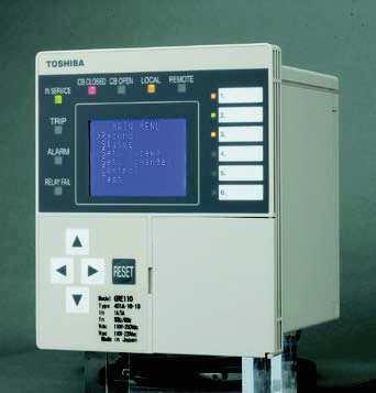
1 Protection and Control for MV Systems
2 FEATURES Overcurrent protection for phase and earth faults (50/5P, 50/5N). Dependent and independent time characteristics (IDMTL and DTL). Four independent current thresholds. Restricted earth fault protection(50/5n). Sensitive earth fault protection (50/5N). Phase undercurrent protection (37). Thermal overload protection (49). Negative phase sequence overcurrent protection (46). Broken conductor detection (46BC). Circuit breaker fail protection (50BF). Cold load protection.. Five shot, three phase auto-reclose (Last trip over the set reclosing shot to lockout) (79). Control function. Local/Remote control. Trip circuit supervision scheme using two binary inputs for high integrity (74TC). Automatic self-supervision. Circuit breaker state monitoring. Programmable Logic Control (PLC) function. Two settings groups. Metering and recording functions. Combined A / 5A current inputs Configurable binary inputs and outputs. Menu-based HMI system. Configurable LED indication. Front mounted USB port for local PC communications. Rear mounted RS485 serial port for remote communications. Data communication with substation control and automation systems is supported according to the Modbus RTU, DNP3, IEC 6850 and IEC standards. APPLICATION GRE0 is a range of fully numerical multi-function protection relays designed for feeder protection applications in medium voltage networks. The devices provide a comprehensive range of protection and control functions within a compact and costeffective package, and can also be applied as motor protection, and as back-up protection for generators and transformers. There are two models within the GRE0 range which differ depending on the application and each model has different types according to the number of binary inputs and outputs fitted, see Table. Combined A/5A current inputs and wide auxiliary supply ranges simplify type selection. Model 400: GRE0-400 GRE0-40 GRE : GRE0-40 GRE0-4 GRE0-4 Table - GRE0 Models Configuration Three Phase Fault and Earth Fault x BIs and 4 x BOs 6 x BIs and 4 x BOs 6 x BIs and 8 x BOs Three Phase Fault, Earth Fault and Sensitive Earth Fault x BIs and 4 x BOs 6 x BIs and 4 x BOs 6 x BIs and 8 x BOs All models include multiple, high accuracy, overcurrent protection elements (for phase and/or earth fault) with inverse time and definite time delay functions in accordance with the IEC functional standard. A comprehensive range of additional protection functions are also supported, including thermal protection to IEC , negative sequence overcurrent protection and a broken conductor detection feature, see Table. Control functions such as two-step operation of circuit breakers are also provided. In addition, GRE0 provided multi-shot, three phase autoreclose, with independent sequences for phase fault, and earth fault and sensitive earth fault. Autoreclose can also be triggered by external protection devises. All models provide continuous monitoring of internal circuits and of software. A trip circuit supervision function using two binary inputs provides highintegrity monitoring of the circuit breaker tripping circuit in both the breaker open and closed conditions. Circuit breaker condition monitoring functions provide guidance of maintenance timing. A user-friendly HMI is provided through a backlit LCD, programmable LEDs, keypad and menu-based operating system. PC access is provided for local connection via a front-mounted USB port. The communication system allows the user to read and modify the relay settings, and to access data gathered by the relay s metering and recording functions. Data available either via the relay HMI or communications ports includes the following functions. Metering Fault recording Event recording Disturbance recording (available via communications ports)
3 Model Number Table - GRE0 Features * Modbus RTU, IEC and DNP3 are supported via built-in RS485 port. PROTECTION FUNCTIONS GRE0-40 Phase Fault Overcurrent Protection 4 Phase Fault O/C (50/5P) Earth Fault O/C (50N/5N) SEF (50N/5N) Phase Undercurrent (37) Thermal Overload (49) NPS Overcurrent (46) Broken Conductor (46BC) Circuit Breaker Fail (50BF) Cold Load Protection Auto Reclose (79) Local/Remote Control Trip circuit supervision (74TC) Self supervision CB State Monitoring Trip Counter Alarm I y Alarm CB Operate Time Alarm Programmable Logic Control (PLC) function Two settings groups Metering Fault records Event records Disturbance records Modbus Communication * * IEC Communication DNP3 Communication * * IEC6850 Communication GRE0 provides three phase overcurrent protection and four independent overcurrent thresholds. The first and second thresholds may be set for inverse time or definite time operation. If inverse time is selected, then any one of nine curves may be chosen, including IEC and IEEE/ ANSI standard characteristics, (see Figure ). The other overcurrent thresholds may be set for definite time, or instantaneous operation. The first threshold has a programmable reset feature, selectable for instantaneous, definite time or dependent time reset. This feature can be used to protect against flashing fault conditions, or to grade correctly with electromechanical overcurrent relays. All elements can be inhibited by binary input signals for operation in blocked overcurrent and busbar blocking protection schemes. Earth Fault Protection The standard earth fault protection is available in all models, and provides four independent overcurrent thresholds. Protection functionality is the same as for the phase fault elements, only with more sensitive current thresholds. For model GRE0-400, 40 and 40, the earth fault quantity is measured directly, either by connecting the input in the residual circuit of the phase CTs, or, as is recommended for more sensitive settings, using a dedicated core balance earth fault CT. For model GRE0-40, 4 and 4, the standard earth fault quantity is derived internally from the residual sum of the three phases. Sensitive Earth Fault Protection (SEF) GRE0-40, 4 and 4 provide 4-stage earth fault protection with more sensitive settings for use in applications where the fault current magnitude may be very low. A -stage overcurrent function is provided, with the first stage programmable for inverse time or definite time operation. The second stage provides inverse or definite time operation and runs after operation of the first stage. Third and fourth overcurrent thresholds are provided, each with a definite time delay. The sensitive earth fault element includes a digital filter which rejects all harmonics other than the fundamental power system frequency. The sensitive earth fault quantity is measured directly, using a dedicated core balance earth fault CT. This input can also be used in transformer restricted earth fault applications, by the use of external metrosils and setting resistors. Phase Undercurrent Protection Protection against loss of load is provided by the phase undercurrent protection. Two independent thresholds are provided, each with a programmable definite time delay. 3
4 Thermal Overload Protection The thermal overload feature provides protection for cables and other plant against the effects of prolonged operation under excess load conditions. A thermal replica algorithm is applied to create a model for the thermal characteristics of the protected plant. Tripping times depend not only on the level of overload current, but also on the level of prior load current, the thermal replica providing memory of previous conditions. The thermal characteristics of the system are defined by entering settings for full load current and thermal time constant. The GRE0 issues a trip according to the cold and hot curves specified in IEC (see Figure ), to prevent the protected system from exceeding its thermal capacity. The cold curve tripping times are applicable when the system is first energised, while the hot curves are relevant when the system has already been carrying some prior load for a period of time. An alarm output is also available to give early warning of high load current, set as a percentage of thermal capacity. Negative Phase Sequence Overcurrent Protection (NPS) NPS protection can be used in applications where certain fault conditions may not be detected by the normal phase and earth overcurrent protections, for example, in the case of a relay applied on the delta side of a delta-star transformer, to detect an earth fault on the star side. Alternatively, NPS can be used to protect a three phase motor against the severe overheating which results from operating with an unbalanced supply. Two independent thresholds are provided, each with a programmable definite time delay. Broken Conductor Protection The unbalance condition caused by an open circuited conductor is detected by the broken conductor protection. An unbalance threshold with programmable definite time delay is provided. Circuit Breaker Fail Protection (CBF) Two stage CBF protection provides outputs for retripping of the local circuit breaker and/or backtripping to upstream circuit breakers. The CBF functions can also be initiated by external protections via a binary input if required. Cold Load Protection The cold load function modifies the overcurrent protection settings for a period after energising the system. This feature is used to prevent unwanted protection operation when closing on to the type of load which takes a high level of current for a period after energisation. This is achieved by a Cold Load Settings Group in which the user can programme alternative settings. Normally the user will choose higher current settings and/or longer time delays and/or disable elements altogether within this group. Auto Reclose (ARC) GRE0 provides an auto-reclose function. Five independent sequences are provided, one for each of the following: Phase fault Earth fault Sensitive earth fault External trip (initiated by a binary input) Each sequence is independently programmable for single shot, two shot, three shot, four shot or five shot (i.e. sixth trip to lock-out when five shot is selected) auto-reclose. Each protection trip is programmable for instantaneous or delayed operation, and each ARC shot has a programmable dead time. Sequence co-ordination is maintained between the auto-reclose sequences of in-series relays on a feeder. Programmable Logic Control (PLC) function User can customize logic function functions on GRE0 such as trip and interlock sequence, etc., using PLC tool software. The PLC data produced by the PLC tool can be downloaded and uploaded to GRE0 via PC communication port. CONTROL FUNCTIONS Switchgear Control GRE0 provides the facility for switchgear control on the relay front panel. Two-stepped operation (selectcontrol) is applied for the control procedure of circuit breakers to ensure highly secure operation. An interlock check function is included for safe operation of the switchgear. Password protection is provided for the above functions. A local/remote selector switch is also provided on the relay front panel so that remote control from station level or load dispatching centre can be chosen. Equipment status (Open or Closed) is indicated on front LEDs and relay fascia LCD. 4
5 Inverse Time Operate and Reset Curves C 000 IEC/UK Inverse Curves (Time Muliplier TMS = ) 00 IEEE/US Inversee Curves (Time Multiplier TMS = ) IEEE/US Reset Curves (Time e Multiplier TMS = ) Operating Time (s) 0 LTI NI VI Operating Time (s) MI VI STI Time (s) 0.00 EI VI I MI 0. EI 0 00 Current (Multiple of Setting) 0. I EI 0 Current (Multiple of Setting) 00 STI Current t (Multiple of Setting) ) t(g k G) = TMS ( G ) Gs + c Inverse time operate function α t r t r ( G) = RTMS G G Dependent time reset function TMS setting range r ; in steps RTMS setting range ; in steps Gs setting range : A in 0.0A steps S Constants for dependent time curves Curve Type (IEC ) A B C D E F Curve Description IEC Normal Inverse (NI) 0.4 IEC Very Inverse I (VI) 3.5 IEC Extremely Inverse (EI) 80 IEEE Moderately Inverse (MI) IEEE Very Inverse (VI) 9.6 IEEE Extremely Inverse (EI) 8. UK Long Time Inverse (LTI) 0 US CO8 Inverse (I) 5.95 US CO Short Time Inverse (STI) k α C t r Figure - Operate and Reset Characteristics 5
6 Thermal Characteristics (to IEC ) Thermal Curves (Cold Curve - no prior load) Thermal Curves (Hot Curve - 90% prior load) Operate Time (minutes) 0 τ=00 τ=50 τ=0 Operate Time (minutes) 0 0. τ=00 τ=500 τ=00 τ=0 τ= τ=5 τ= τ= τ=55 τ= τ= 0 Overload Current (Multiple of k.i FLC ) Overload Current (Multiple of k.i FLC C) t = τ.ln I I ( k I. FLC C ) ; t = τ.ln I I ( I k.ii P FLC ) IEC Cold Curvee IEC Hot Curve t = time to trip for constant overload current I (seconds) I = overload current (largest phase current) ) (pu) I P = previous load current (pu) k.i FLC (or I θ ) = thermal overload current setting (pu) τ = thermal time constant (seconds) Ln = natural logarithm Figure - Thermal Characteristics in accordance with w IEC
7 MONITORING FUNCTIONS Trip Circuit Supervision GRE0 provides a high-integrity trip circuit supervision scheme. Trip circuits can be monitored with the circuit breaker either closed or open using two binary inputs as shown in Figure 3. Figure 3 Trip Circuit Supervision Scheme CB Closed: Under healthy conditions, binary input BI is energised via external resistor, R. If the trip circuit becomes open, BI resets and a Trip Circuit Fail alarm is raised. CB Open: Under healthy conditions, binary inputs BI & BI are energised via external resistors, R & R respectively. If the trip circuit becomes open, both inputs reset and a Trip Circuit Fail alarm is raised. The Trip Circuit Fail alarm incorporates a time delay of 400ms to prevent false alarms during normal tripping operations or voltage dips and is given in the form of an output contact operation and LCD/LED indication. Automatic Self-Supervision Automatic monitoring of internal circuits and software is provided. In the event of a failure being detected, the ALARM LED or the RELAY FAIL on the relay front panel is illuminated, the RELAY FAILURE binary output operates, and the date and time of the failure is recorded in the event record. Circuit Breaker State Monitoring If two binary inputs are programmed to the functions CB OPEN and CB CLOSED then the CB State Monitoring function becomes active. In normal circumstances these inputs are in opposite states. If both show the same state then a CB Defective alarm is raised. Circuit Breaker Condition Monitoring The following CB condition monitoring functions are provided: The trip counter increments the number of tripping operations performed. An alarm is issued when the count exceeds a user-defined setting. The I y counter increments the value of current to the power y, recorded at the time of issuing the tripping signal, on a phase by phase basis. An alarm is issued when the count for any phase exceeds a user-defined setting. The operating time monitor records the time between issuing the tripping signal and the phase currents falling to zero. An alarm is issued when the operate time for any phase exceeds a userdefined setting. The CB condition monitoring functions are triggered each time a trip is issued, and they can also be triggered by an external device via a binary input. METERING AND RECORDING Metering The following data is continuously available on the relay front panel LCD and at a local or remote PC. Primary and secondary currents for each input. Positive and negative phase sequence currents. Ratio of negative phase sequence to positive phase sequence currents. Peak phase current demand. Thermal condition of system. Relay element output status. Binary input and output status. Event Record Records are stored for the 00 most recent events, time-tagged to ms resolution. The event record is available on the relay front panel LCD and at a local or remote PC. Events are recorded as follows: Tripping operations. Alarms. Operation of protection elements. Change of state of binary inputs / outputs. Change of relay setting. Failure detected by automatic supervision. Fault Record A relay trip initiates fault recording. Records are stored for the 4 most recent faults, time-tagged to ms resolution. The fault record is available on the relay front panel LCD and at a local or remote PC. Fault records include the following data: 7
8 Date and time of trip operation. Operating phase. Protection scheme responsible for trip. Measured current data. Disturbance Record The relay can record 4 analog and 3 binary signals, initiated by relay tripping. The post-trigger recording time can be set, and the maximum number of records which can be stored is dependent on the recording time chosen. Date and Time GRE0 provides a date and time feature for tagging of records. USER INTERFACE Relay Front Panel A user friendly interface is provided on the relay front panel. A menu-based system provides for easy programming of relay functions and access to realtime and stored data. The front panel includes the following features. 6 character, 8-line LCD with backlight. 4 LEDs (8 fixed display and 6 configurable). Keypad. USB.0 port for connection of local PC. Local PC Connection The user can communicate with the GRE0 from a local PC via the USB.0 port on the front panel. Using RSM00 software, the user can view and modify settings, monitor real-time metering and analyse recorded data. Figure 4 shows the configuration of typical displays from the RSM00 software. Modbus and DNP3 Communications GRE0 supports the Modbus and DNP3 communication protocol. These protocols are used for communication with a substation control and monitoring system or automation system to be linked with SCADA or regional control center, and are used to transfer measurand data, status data and general commands between the relay and the control system. IEC Communications GRE0 supports the IEC communication protocol. This protocol is used for communication with a substation control and monitoring system and is used to transfer measured data, status data and general commands between the relay and the control system via RS485. IEC 6850 Communication GRE0 can support data communication according to the IEC 6850 standard via an optional communication port. Relay Setting The user can modify relay settings either using the front panel keypad or using the RSM00 software from a local PC. Password protection is available for added security. Two settings groups are provided, allowing the user to set one group for normal conditions, while the other group may be set to cover alternative operating conditions. Using the RSM software, the user can create a settings file on a PC (without being connected to a relay), and store the file ready for download to a relay at a later date. Binary Outputs GRE0 provides four or eight user programmable binary output contacts for tripping and alarm. Each of the programmable binary outputs is driven via a logic gate which can be programmed for OR gate or AND gate operation. Further, each output has a programmable reset characteristic, settable for instantaneous drop-off, delayed drop-off, or for latching operation. If latching operation is selected then an operated relay must be reset by the user, either by pressing the RESET button, by energising a binary input which has been programmed for Remote Reset operation, or by a communications command. Binary Inputs GRE0 provides two programmable binary inputs as standard and a further four available as an option. Each binary input is individually user-programmable for normal or inverted operation and for delayed pickup and/or drop-off. Each input can also be used to switch relay operation to a different settings group. General purpose alarm functions are also included. The user can define a text message for each alarm. Then when inputs associated with that alarm are raised, the defined text is displayed on the LCD. 8


9 PC DISPLAY Setting Event record Metering Data analysis Fault record Figure 4 - Relay Setting and Monitoring System - PC Displays 9
10 TECHNICAL DATA Ratings AC current I n : Frequency: Auxiliary supply: /5A (combined) 50/60Hz 0-50Vdc or 00-0Vac (Operative range: Vdc / 80 64Vac) 48-0Vdc (Operative range: Vdc) 4-48Vdc (Operative range: Vdc) Superimposed AC ripple on DC supply: maximum % DC supply interruption: maximum 50ms at 0V Binary input circuit DC voltage: For alarm indication 0-50Vdc (Operative range: Vdc) 48-0Vdc (Operative range: Vdc) 4-48Vdc (Operative range: Vdc) For trip circuit supervision Operative range: 38.4V (for 0Vdc rating) 88V (for 0/50Vdc rating) 9.V (for 48Vdc rating) 9.6V (for 4Vdc rating) Overload Ratings AC phase current inputs: Burden AC phase current inputs: AC earth current inputs: AC sensitive earth inputs: DC power supply: Binary input circuit: Measuring input capability 4 times rated current continuous 00 times rated current for second 0.VA 0.4VA.VA 0W (quiescent) 5W (maximum) 0.5W per input at 0Vdc Full scale 3 phase current input 04.8A Earth fault current input (EF:40xA model) 0.48A Sensitive earth fault current input 0.384A (SEF; 4xA or 8xA model) Voltage input (8xA model) 45.76V Sampling rate 48 samplings / Cycle Current Transformer Requirements Phase Inputs Standard Earth Inputs: Sensitive Earth Inputs: Phase Overcurrent Protection (50, 5) Typically 5P0 with rated burden according to load, (refer to manual for detailed instructions). Core balance CT or residual connection of phase CTs. Core balance CT. st, nd Overcurrent threshold: OFF, A in 0.0A steps Delay type: DTL, IEC NI, IEC VI, IEC EI, UK LTI, IEEE MI, IEEE VI, IEEE EI, US CO8 I, US CO STI 0
11 IDMTL Time Multiplier Setting TMS: in 0.00 steps DTL delay: s in 0.0s steps Reset Type: Definite Time or Dependent Time. Reset Definite Delay: s in 0.s steps Reset Time Multiplier Setting RTMS: in 0.00 steps 3 rd, 4 th Overcurrent thresholds: OFF, A in 0.0A steps DTL delay: s in 0.0s steps Earth Fault Protection (50N, 5N) st, nd Overcurrent threshold: OFF, A in 0.0A steps Delay type: DTL, IEC NI, IEC VI, IEC EI, UK LTI, IEEE MI, IEEE VI, IEEE EI, US CO8 I, US CO STI IDMTL Time Multiplier Setting TMS: in 0.00 steps DTL delay: s in 0.0s steps Reset Type: Definite Time or Dependent Time Reset Definite. Delay: s in 0.s steps Reset Time Multiplier Setting RTMS: in 0.00 steps 3 rd, 4 th thresholds: OFF, A in 0.0A steps DTL delay: s in 0.0s steps Sensitive Earth Fault Protection (50Ns, 5Ns) st, nd Overcurrent threshold: OFF, A in 0.00A steps Delay Type: DTL, IEC NI, IEC VI, IEC EI, UK LTI, IEEE MI, IEEE VI, IEEE EI, US CO8 I, US CO STI Stage TMS: in 0.00 steps Stage DTL delay: s in 0.0s steps Stage Reset Type: Definite Time or Dependent Time Stage Reset Def. Delay: s in 0.s steps Stage RTMS: in 0.00 steps Stage DTL delay: s in 0.0s steps 3 rd, 4 th thresholds: OFF, A in 0.00A steps DTL delay: s in 0.0s steps Phase Undercurrent Protection (37) st, nd threshold: OFF, A in 0.0A steps DTL delay: s in 0.0s steps Thermal Overload Protection (49) I θ = k.i FLC (Thermal setting): Time constant (τ): Thermal alarm: Negative Phase Sequence Protection (46) OFF, A in 0.0A steps mins in 0.min steps OFF, 50% to 99% in % steps st, nd threshold: OFF, A in 0.0A steps DTL delay: s in 0.0s steps Broken Conductor Protection (46BC) Broken conductor threshold (I /I ): DTL delay: CBF Protection (50BF) CBF threshold: CBF stage DTL: CBF stage DTL: OFF, in 0.0 steps s in 0.0s steps OFF, A in 0.0A steps s in 0.0s steps s in 0.0s steps
12 Inrush Current Detector Second harmonic ratio setting (I f /I f ): Overcurrent thresholds: Autoreclose (79) ARC Reclaim Time Close Pulse Width Lock-out Recovery Time Sequences Dead Times (Programmable for each shot) Accuracy 0 50% in % steps A in 0.0A steps s in 0.s steps s in 0.0s steps OFF, s in 0.s steps -5 Shots to Lock-out, each trip programmable for inst or Delayed operation s in 0.0s steps IDMTL Overcurrent Pick-up: All Other Overcurrent Pick-ups: 05% of setting ± 5% 00% of setting ± 3% (Gs>0.A) Overcurrent PU/DO ratio: approx, 00% Undercurrent Pick-up: 00% of setting ± 3% (Gs>0.A) Undercurrent PU/DO ratio: approx, 05% Inverse Overcurrent Operate Time: IEC6055-5, ±5% or 50ms ( G/Gs 0) OC Definite Operate Time EF Definite Operate Time UC Operate Time NPS Operate Time CBF Operate Time Transient Overreach for instantaneous elements: Thermal Overload Operate Time G T =.Gs G D = 0Gs (Gs 0A), 00A (Gs > 0A) DTL + 45ms (DT, input: 00% of setting) DTL + 45ms (DT, input: 00% of setting) DTL + 85ms (input: 80% of setting) DTL + 50ms (input: 00% of setting) DTL + 30ms (input: 00% of setting) <5% 5% (input: 00% of setting) Time delays includes operating time of trip contacts Front Communication port - local PC (USB) Connector type: USB-Type B Cable length: 5m (max.) Rear Communication port - remote PC (RS485) Connection: Cable type: Cable length: Connector: Isolation: Transmission rate: Rear Communication port (Ethernet) 00BASE-TX 00BASE-FX Multidrop (max. 3 relays) Twisted pair 00m (max.) Screw terminals kvac for min. 9. kbps RJ-45 connector SC connector
13 Binary Inputs Operating Voltage Binary Outputs Number Ratings model 4 0 and 4 ; BO# and # model 4 : BO#,#,#5 and #6 For alarm indication Typical 54Vdc (min. 0Vdc) for 0Vdc rating Typical 77Vdc (min. 70Vdc) for 0Vdc rating Typical 33.6Vdc (min. 4Vdc) for 48Vdc rating Typical 6.8Vdc(min. Vdc) for 4Vdc rating For trip circuit supervision 88V for 0/50Vdc rating 38.4Vdc for 0Vdc rating 9.V for 48Vdc rating 9.6V for 4Vdc rating 4 or 8 (excluding Relay Fail contact) Make and carry: 5A continuously Make and carry: 30A, 50Vdc for 0.5s (L/R 40ms) Break: 0.A, 50Vdc (L/R=40ms) other BOs Durability: Pickup time: Reset time: Mechanical design Weight Width Height Depth Case color Installation Make and carry: 4A continuously Make and carry: 8A, 50Vdc for 0.s (L/R 40ms) Break: 0.A, 50Vdc (L/R=40ms) Loaded contact:,000 operations Unloaded contact: 0,000 operations Less than 5ms Less than 0ms.5kg for model 400A, 40A, 40A and 4A.8kg for model 40A and 4A 49mm for model 400A, 40A, 40A and 4A 3mm for model 40A and 4A 77mm 68mm Munsell No. 0YR8/0.5 Flush mounting with attachment kits ENVIRONMENTAL PERFORMANCE Test Standards Details Atmospheric Environment Temperature IEC / IEC Operating range: -0 C to +60 C. Storage / Transit: -5 C to +70 C. Humidity IEC days at 40 C and 93% relative humidity. Enclosure Protection IEC 6059 IP5 (front), IP0 (rear), IP40 (top) Mechanical Environment Vibration IEC Response - Class Endurance - Class Shock and Bump IEC Shock Response Class Shock Withstand Class Bump Class 3

14 Test Standards Details Seismic Electrical Environment Dielectric Withstand High Voltage Impulse IEC IEC IEEE C IEC Class kvrms for minute between all terminals and earth. kvrms for minute between independent circuits. kvrms for minute across normallyy open contacts. Three positive and three negative impulses of 5kV(peak) for CT, Power Supply Unit, BI and BO circuits; between terminals and a earth, and d between independent circuits 3kV (peak) for RS485 circuit; between terminalss and earth 3kV (peak) for BO circuit; across normally open contacts./50µs, 0.5J betweenn all terminalss and between all terminals and earth. Electromagnetic Environment High Frequency Disturbance / Damped Oscillatory Wave Electrostatic Discharge Radiated RF Electromagnetic Disturbance Fast Transient Disturbance Surge Immunity Conductedd RF Electromagnetic Disturbance Power Frequency Disturbance Power Frequency Magnetic Field Conductedd and Radiated Emissions IEC Class 3, IEC IEEE C IEC IEC Ed.3 IEC Class 3, IEC IEC Ed.3 IEC Class 3, IEC IEC Ed.3 IEC Class A, IEC , IEEE C IEC Ed.3 IEC , IEC IEC Ed.3 IEC Class 3, IEC IEC Ed.3 IEC Class A, IEC IEC Ed.3 IEC Class 4 IEC Ed 3 IEC , EN 550 Class A, IEC IEC Ed.3 MHz.5kV to 3kV (peak) applied too all ports without communication ports inn common mode. MHz.0kV applied too communication ports in common mode. MHz.0kV applied too all ports without communication ports in differential mode. 6kV contact discharge,, 8kV air discharge. Field strength 0V/m for frequency sweeps of 80MHz to GHz and.4ghz to.7ghz. Additional spot tests at 80, 60, 450, 900,850 and 50MHz. 5 khz, 5/ /50ns disturbance All inputs without Communication ports:4kv Communication ports:kv./50µs surge in common/differential modes: Communication port: kv/kv/0.5kv V, line to earth Other ports: kv/kv/0.5kv, line to earth kv/0.5kv, line to line 0Vrms applied over frequency range 50kHz to 00MHz. Additional spot tests att 7 and 68MHz. 300V 50Hz for 0s applied to ports in common mode. 50V 50Hz for 0s applied to ports in differential mode. Not applicable to AC inputs. Field applied at 50/60Hz with strengths of: 30A/m continuously, 300A/m for second. Conducted emissions: 0.5 to 0.50MHz: <79dB (peak) or < <66dB (mean) 0.50 to 30MHz: <73dBB (peak) or <60dB (mean) Radiatedd emissions (at 0m): 30 to 30MHz: <40dB 30 to 000MHz: <47dB G to 3GHz: <56dB European Commission Directives 89/336/EEC Compliance with the European E Commission Electromagnetic Compatibility Directive is demonstrated according to generic EMC standards EN and EN
15 Test Standards Details 73/3/EEC Compliance with the European Commission Low Voltage Directive is demonstrated according to product safety standard EN
16 ORDERING Overcurrent Relay GRE0 A Type: Overcurrent Protection Relay Model: - Model 400: Three phase and earth fault x BIs, 4 x BOs, x Relay fail 6 x BIs, 4 x BOs, x Relay fail 6 x BIs, 8 x BOs, x Relay fail - Model 40: Three phase and sensitive earth fault x BIs, 4 x BOs, x Relay fail 6 x BIs, 4 x BOs, x Relay fail 6 x BIs, 8 x BOs, x Relay fail Rating: CT: /5A, f: 50/60Hz, 0-50Vdc or 00-0Vac CT: /5A, f: 50/60Hz, 48-0Vdc CT: /5A, f: 50/60Hz, 4-48Vdc Standard and language: GRE0 IEC (English) 0 Communication: RS485 port (Modbus/IEC ) RS485 port (Modbus/DNP3) 00BASE-TX port (Modbus/IEC 6850) +RS485 port (Modbus/IEC ) 00BASE-TX port (Modbus/IEC 6850/DNP3) +RS485 port (Modbus/DNP3) 00BASE-FX port (Modbus/IEC 6850) +RS485 port (Modbus/IEC ) 00BASE-FX port (Modbus/IEC 6850/DNP3) +RS485 port (Modbus/DNP3) A 0 A0 A C0 C 6
17 TYPICAL APPLICATIONS / CONNECTIONS *BO3 and BO4 are NOT applicable for direct CB coil connection. **Analogue current input ports are shorted when the terminal block is removed. (TB -, 3-4, 5-6, 7-8) Figure 5 - GRE0-400A Typical Application Diagram 7
18 *BO3 and BO4 are NOT applicable for direct CB coil connection. **Analogue current input ports are shorted when the terminal block is removed. (TB -, 3-4, 5-6, 7-8) Figure 6 - GRE0-4A Typical Application Diagram 8
19 *BO3, BO4, BO7 and BO8 are NOT applicable for direct CB coil connection. **Analogue current input ports are shorted when the terminal block is removed. (TB -, 3-4, 5-6, 7-8) *** Available at one of the communication function is selected. Figure 7 - GRE0-40A Typical Application Diagram 9

20 RELAY OUTLINE Figure 8 - GRE0 Outline Diagram Model 400/40/40/4 0

21 Figure 9 - GRE0 Outline Diagram Model 40/4
22 GRE , Horikawa-cho, Saiwai-ku, Kawasaki -8585,, Japan Tel Fax // - The information provided in this catalog iss subject to change without notice. - The information provided in this catalog iss accurate as of October The information provided in this catalog iss presented only as a guide for the application of TOSHIBAA products. No responsibility is assumed by TOSHIBA for any infringements of patentss or other rights of third parties which may result from its use. No license l is granted byy implication or otherwise under any patent or patent rights of TOSHIBA or others. - TOSHIBA products should not be embedded within downstream products production and sale of which are prohibited, under anyy law and regulation. - Toshiba does not take any a responsibility for incidental damage (including loss of business profit, businesss interruption, loss of business information and other pecuniary damage) arising out of the t use or misuse off TOSHIBA products. GKP Rev. Copyright 07 Toshiba Energy Systems & Solutions Corporation. All rights reserved.
GRE120. Motor Protection and Control for MV Systems
 Motor Protection and Control for MV Systems FEATURES Overcurrent protection for phase and earth faults (50/51P, 50/51N). Dependent and independent time characteristics (IDMTL and DTL). Restricted earth
GRD110 FEATURES APPLICATION
 FEATURES Overcurrent protection for phase and earth faults with IDMTL or DTL. Three instantaneous elements with DTL. Programmable reset characteristics. Sensitive earth fault protection (SEF). Restricted
GRE130. Protection and Control for MV Systems
 Protection and Control for MV Systems FEATURES Phase undervoltage protection with IDMTL or DTL(27). Phase overvoltage protection with IDMTL or DTL(59). Zero phase sequence overvoltage (neutral voltage
GRD130 - FEATURES APPLICATION
 FEATURES Phase undervoltage protection with IDMTL or DTL. Phase overvoltage protection with IDMTL or DTL. Zero phase sequence overvoltage (neutral voltage displacement) protection with IDMTL/DTL. Negative
GRE140. Protection and Control for MV Systems
 Protection and Control for MV Systems FEATURES Four stage non-directional and directional overcurrent protection for phase and earth faults with IDMTL or DTL. Polarizing voltage memory. Directional earth
GRE160. Transformer Protection
 Transformer Protection FEATURES Fully numerical transformer protection Current differential protection for two-winding transformers with inrush restraint (87T) High-set differential overcurrent protection
Table 1 Relay Model and Function
 FEATURES Numerical autoreclosing function Single-shot, single-phase and/or three-phase autoreclose scheme for one or two circuit breakers Multi-shot (selectable between 2 and 4) threephase autoreclose
GRD150. FEATURES Protection functions. Control functions. Monitoring and Metering. Recording. User Interface APPLICATION
 FEATURES Protection functions Non-directional and directional overcurrent and earth-fault protection and sensitive earth fault protection (option) Overvoltage and undervoltage protection Thermal overload
INSTRUCTION MANUAL TRIP CIRCUIT SUPERVISION RELAY GKAD1
 INSTRUCTION MANUAL TRIP CIRCUIT SUPERVISION RELAY GKAD1 TOSHIBA Corporation 2004 All Rights Reserved. ( Ver. 1.6 ) Safety Precautions Before using this product, please read this chapter carefully. This
MiCOM P122C Time-Overcurrent Protection
 Protection Relays 01 MiCOM P122C Time-Overcurrent Protection Customer Benefits 1A/5A software setting 4 function keys Compact unit for flush and wall-surface mounting Comprehensive measurements Disturbance
General catalog. Copyright 2017 Toshiba Energy Systems & Solutions Corporation. All rights reserved.
 General catalog 72-34, Horikawa-cho, Saiwai-ku, Kawasaki 212-8585, Japan Tel +81-44-331-1462 Fax +81-44-548-9540 http://www.toshiba-relays.com - The information provided in this catalog is subject to change
Bus Bar Protection Relay B-PRO 4000
 Bus Bar Protection Relay B-PRO 4000 Product Overview The IEC 61850 station bus embedded B-PRO 4000 relay provides complete bus and substation differential protection (low impedance) with CT saturation
MiCOM P124 T&D. Self and Dual Powered Overcurrent Relays
 PROTECTION MiCOM P124 Self and Dual Powered Overcurrent Relays MiCOM P124 are numerical relays designed to offer complete overcurrent protection without requiring any external auxiliary supply. They can
GRT100 FEATURES APPLICATION
 FEATURES Fully numerical transformer protection Current differential protection for two-winding or three-winding transformers High-set differential overcurrent protection No interposing CTs required CT
General catalog. Energy Systems & Solutions Company A2. Copyright 2017 Toshiba. All rights reserved.
 General catalog Energy Systems & Solutions Company 72-34, Horikawa-cho, Saiwai-ku, Kawasaki 212-8585, Japan Tel +81-44-331-1462 Fax +81-44-548-9540 http://www.toshiba-relays.com - The information provided
Type MVTT 14 and MVTT 15: Static Digital Time delay relays
 Type MVTT 4 and MVTT 5: Static Digital Time delay relays Features 000/ setting range Time settings easily selected by means of thumbwheel switches Provide time delayed pick-up, or drop-off Compact construction
Relion 605 series. Self-powered feeder protection REJ603 Product Guide
 Relion 605 series Relion 605 series Relion 605 series Self-powered feeder protection Product Guide Product version: 3.0 Contents 1. Description... 3 2. Relay functions... 3 3. Protection functions... 4
Overcurrent and Arc Protection by Reyrolle Alexander Erokhin. 21, 2017 I Berlin
 Overcurrent and Arc Protection by Reyrolle Alexander Erokhin VAR Partner Day September 20-21, 21, 2017 I Berlin Reyrolle Product Range by SIEMENS Challenges We Meet for our Customers Easy-to-use protection
MiCOM P124. Self and Dual Powered Overcurrent Relays. Protection Relays
 01 Self and Dual Powered Overcurrent Relays are numerical relays designed to offer complete overcurrent protection without requiring any external auxiliary supply. They can be applied to a wide variety
MiCOM P521. Fast feeder differential protection
 01 Fast feeder differential protection The relay provides high-speed two-ended current differential unit protection of overhead lines and underground cables in applications such as ring mains and parallel
SIPROTEC easy 7SJ45 Numerical Overcurrent Protection Relay Powered by CTs
 SIPROTEC easy 7SJ4 Numerical Overcurrent Protection Relay Powered by CTs Function overview Fig. /1 Description The SIPROTEC easy 7SJ4 is a numerical overcurrent protection relay which is primarily intended
MiCOM P521. Fast Feeder Differential Protection
 01 Fast Feeder Differential Protection The relay provides high-speed two-ended current differential unit protection of overhead lines and underground cables in applications such as ring mains and parallel
Multi Function Protection IED
 Multi Function Protection IED GR-200 series - The GR-200 Series is Toshiba s next generation of protection and control IED s, designed for transmission/distribution networks and providing a platform for
Reyrolle Protection Devices. 7SG13 Delta Protection and Control Relays. Answers for energy
 Reyrolle Protection Devices 7SG13 Delta Protection and Control Relays Answers for energy 7SG13 Delta Protection and Control Relays User Interface 20 character x 2 line backlit LCD Menu navigation keys
Protection Relays PHASE & RESIDUAL OVERCURRENT
 Protection Relays PHASE & RESIDUAL OVERCURRENT Application The relay type NA016 can be used in radial networks as feeder or power transformer protection. In solidly grounded systems the residual overcurrent
7SR18 Solkor Line Differential Protection Energy Management
 Reyrolle Protection Devices 7SR18 Solkor Line Differential Protection Energy Management 7SR18 Solkor five or eight user-programmable binary output contacts and three or six user programmable status inputs
- Control and monitoring of switchgear, transformers and other equipment or devices in EHV, HV, MV and LV substations
 Bay Control IED GR-200 series - The GR-200 Series is Toshiba s next generation of protection and control IED s, designed for transmission/distribution networks and providing a platform for distributed
7SR21 Non-Directional 7SR22 Directional Overcurrent Relay
 7SR21 Non-Directional 7SR22 Directional Overcurrent Relay Document Release History This document is issue 2010/05. The list of revisions up to and including this issue is: 2010/05 Additional Comms modules
General catalog AP. Copyright 2014 Toshiba. All rights reserved.
 General catalog 72-34, Horikawa-cho, Saiwai-ku Kawasaki-shi, Kanagawa 212-8585, Japan Tel +81-44-331-1462 Fax +81-44-548-9540 http://www.toshiba-relays.com - The information provided in this catalog is
Feeder Protection Relay REF 610. Product Guide
 Product Guide Contents 1 Description.............................. 3 2 Protection functions....................... 3 3 Measurement............................ 4 4 Disturbance recorder......................
VIP 40/45 VIP 400/410
 40/45 400/410 Selection guide 01 PM100573 40/45 PM100576 400/410 self-powered integrated protection relay Optimised performance for transformer, incomer, feeder and bus riser protection Complete engineered
MINER-S Station Controller
 MINER-S Station Controller Substation Automation MINER-S Station Controller The MINER-S Station Controller is a SCADA enabled fixed point remote terminal unit (RTU) with a data concentrator, event reporter,
Combined Overcurrent and Earth-fault Relay SPAJ 140 C. Product Guide
 Combined Overcurrent and Earth-fault Product Guide Issued: April 1999 Status: Updated Version: C/18.04.2006 Data subject to change without notice Features Three-phase, low-set phase overcurrent unit with
MiCOM P521. Fast Feeder Differential Protection. Protection Relays. MiCOM P521 CUSTOMER BENEFITS
 MiCOM 01 MiCOM Fast Feeder Differential Protection The MiCOM relay provides high-speed two-ended current differential unit protection of overhead lines and underground cables in applications such as ring
Feeder/ Motor Protection Relay VAMP 40
 Feeder/ Motor Protection Relay Feeder/motor protection relay Main characteristics Complete protection Comprehensive selection of protection functions for distribution network overhead line feeders, cable
Reyrolle Protection Devices. 7SR11 and 7SR12 Argus Overcurrent Relays. Answers for energy
 Reyrolle Protection Devices 7SR11 and 7SR12 Argus Overcurrent Relays Answers for energy 7SR11 and 7SR12 Argus Overcurrent Relays Control 79 Auto Reclose 86 Lockout CB Control Features Cold Load Settings
Reyrolle Protection Devices. 7SR10 Argus User Manual Overcurrent and Earth Fault Relay
 Reyrolle Protection Devices 7SR10 Argus User Manual Overcurrent and Earth Fault Relay Siemens Protection Devices Limited 2 7SR10 Argus Contents Contents Technical Manual Chapters 1. Description of Operation
Earth-fault Relay SPAJ 110 C. Product Guide
 Issued: April 1999 Status: Updated Version: C/12.04.2006 Data subject to change without notice Features Low-set neutral overcurrent stage with definite time or inverse time characteristic High-set neutral
Protection relays.
 Protection relays www.vamp.fi Vamp Ltd Vamp Ltd, with a strong experience of designing devices, is an independent supplier of relays and monitoring equipment. The company has an established reputation
Scout-S Station Controller
 Scout-S Station Controller Substation Automation Scout-S Station Controller The Scout-S Station Controller is a SCADA enabled remote terminal unit (RTU) with a data concentrator, event reporter, and built-in
Reyrolle Protection Devices. 7SR10 Argus Overcurrent and Earth Fault Relay
 Reyrolle Protection Devices 7SR10 Argus Overcurrent and Earth Fault Relay 7SR10 Argus Overcurrent and Earth Fault Relay Control 79 Auto Reclose 86 Lockout CB Control CB Trip/Close Features Cold Load Settings
Transformer Protection Relay
 Transformer Protection Relay T-PRO Product Overview The IEC 61850 station bus embedded T-PRO relay provides complete three-phase multi-winding transformer protection and overload protection, DFR-quality
For Transmission, Distribution and Machinery protection.
 Founded in 1953, Microelettrica Scientifica has developed a wide range of products, divided into three main lines: For Transmission, Distribution and Machinery protection. A-Line Electronic analogic. M-Line
Relion 611 series. 611 series Type Test Certificate
 Relion 611 series 611 series Document ID: 1MRS757466 Issued: 2016-02-22 Revision: B Product version: 2.0 Copyright 2016 ABB. All rights reserved Table of contents Table of contents Section 1 Section
(1) Description of Operation 7SR224 Recloser Controller
 Description of Operation 7SR224 Recloser Controller") (1) Description of Operation 7SR224 Recloser Controller DOCUMENTATION SET This document is part of a set. The full list of documents in the set, and the publication numbers under which they can be ordered,
(1) Description of Operation 7SR224 Recloser Controller DOCUMENTATION SET This document is part of a set. The full list of documents in the set, and the publication numbers under which they can be ordered,
Reyrolle Catalogue Answers for Energy
 Reyrolle Protection Devices Reyrolle Catalogue Answers for Energy Index Compact Overcurrent Argus C 7SR11 & 7SR12 1 Multifunction Overcurrent Argus M 7SR21 & 7SR22 2 Multifunction Reclose Controller Recloser
Sensitive Earth-fault Relay SPAJ 111 C. Product Guide
 Issued: April 1999 Status: Update Version: C/12.04.2006 Data subject to change without notice Features Sensitive low-set neutral overcurrent stage with definite time characteristic High-set neutral overcurrent
Reyrolle Protection Devices. 7SG117 Argus 7 Synchronising Relay. Answers for energy
 Reyrolle Protection Devices 7SG117 Argus 7 Synchronising Relay Answers for energy 7SG117 Argus 7 Synchronising Relay Fig 1. Independent check & system synchronising settings Adjustable slip frequency,
PROTECTION RELAYS THE ULTRA LINE NUMERICAL MULTIFUNCTION INTELLIGENT DEVICE FOR PROTECTION, SUPERVISION, METERING AND CONTROL
 MICROPROCESSOR PROTECTION RELAYS THE ULTRA LINE NUMERICAL MULTIFUNCTION INTELLIGENT DEVICE FOR PROTECTION, SUPERVISION, METERING AND CONTROL MICROELETTRICA SCIENTIFICA MANUFACTURES A COMPLETE RANGE OF
INTRODUCTION. The PL-50 MO and PM-250 families represent the. PM-250-H: Horizontal box. PM-250-V: Vertical box
 INTRODUCTION The PL-50 MO units are available in the next mechanical version: The PL-50 MO and PM-250 families represent the different solutions that Team Arteche offers for motor protection. Both families
Feeder protection relay SPAA 341 C. Product Guide
 Issued: April 1999 Status: Updated Version: D/07.03.2006 Data subject to change without notice Features Comprehensive numerical feeder protection relay consisting of two multi-function protection relay
Communication Gateway COM 610. Product Guide
 Communication Gateway COM 610 Product Guide Issued: September 2004 Status: Updated Version: D/17.10.2006 Data subject to change without notice Features Protocol conversion gateway for substation automation:
REL52002 Easergy P3U30, 4L, 4U, 16DI/8DO, Uaux: V, DI: V, RS-485
 Characteristics Easergy P3U30, 4L, 4U, 16DI/8DO, Uaux: 48-230V, DI: 220-230V, RS-485 Main Range of product Product or component type Relay application Device short name [Us] rated supply voltage Type of
7SR11 and 7SR12 Argus Overcurrent Relays Answers for infrastructure & cities.
 Reyrolle Protection Devices 7SR11 and 7SR12 Argus Overcurrent Relays Answers for infrastructure & cities. 7SR11 and 7SR12 Argus Overcurrent Relays Supervision 60CTS CT Supervision 74T/CCS Trip & Close
Reyrolle Protection Devices. 7SR11 and 7SR12 Argus Overcurrent Relays. Answers for energy
 Reyrolle Protection Devices 7SR11 and 7SR12 Argus Overcurrent Relays Answers for energy 7SR11 and 7SR12 Argus Overcurrent Relays 74T/CCS Trip & Close Circuit Supervision 60VTS VT Supervision Control 79
Transformer Protection IED
 Transformer Protection IED GR-00 series - The GR-00 Series is Toshiba s next generation of protection and control IED s, designed for transmission/distribution networks and providing a platform for distributed
Reyrolle Protection Devices. 7SR210 & 7SR220 Argus Overcurrent Protection Relay. Answers for energy
 Reyrolle Protection Devices 7SR10 & 7SR0 Argus Overcurrent Protection Relay Answers for energy 7SR10 7SR0 Argus Overcurrent Protection Relay Additional Functionality 7SR0n Directional Relay 7/59 Under/Over
Arc protection relay. Features Three-phase overcurrent function. Application
 Arc protection relay REA 10_ Page 1 Issued: May 1999 Status: New Data subject to change without notice Features Three-phase overcurrent function Loop-type or radial sensor fibre for arc detection Two high-speed
MINER-S Station Controller. Substation Automation
 Substation Automation MINER-S Station Controller incorporates traditional RTU functions with new technology in a compact design MINER-S Station Controller combines the functions of a traditional RTU with
Multi Function Protection IED
 Multi Function Protection IED GR-200 series - The GR-200 Series is Toshiba s next generation of protection and control IED s, designed for transmission/distribution networks and providing a platform for
NPW800R RETROFITTING. Power and Volatge Protection Relay
 RETROFITTING Power and Volatge Protection Relay NPW800R (R3 case) is dedicated to the refurbishment of CEE WTG 7000 relays (R3 case) providing the measurement of apparent (S), active (P) and reactive (Q)
7SR105 Rho User Manual Motor Protection Relay Energy Management
 Reyrolle Protection Devices 7SR105 Rho User Manual Motor Protection Relay Energy Management 2016 Siemens Limited 2 7SR105 Rho Contents Contents Technical Manual Chapters 1. Description of Operation 2.
Feeder protection relay
 Page 1 Issued: April 1999 Status: New Data subject to change without notice Features Comprehensive numerical feeder protection relay consisting of two multi-function protection relay modules and a flexible
7SR23 DAD High Impedance Protection Relay Energy Management
 Reyrolle Protection Devices 7SR23 DAD High Impedance Protection Relay Energy Management 2 Siemens Protection Devices Limited 7SR23 DAD High Impedance Relay User Interface 20 character x 4 line backlit
MAPro10 Numerical 3phase over current + earth fault relay
 MAPro10 Numerical 3phase over current + earth fault relay 1 T S: STANDARD SAFETY STATEMENTS S 1: Attention: The information in the Safety Section of the equipment documentation is intended to ensure that
Sensitive definite time or inverse time earth-fault stage for back-up residual earthfault
 Issued: April 1999 Status: Updated Version: B/09.11.2001 Data subject to change without notice Features Sensitive restricted earth-fault protection stage for fast, selective earth-fault protection Sensitive
7SR11 and 7SR12 Description of Operation
 7SR11 and 7SR12 Description of Operation Document Release History This document is issue 2012/02. The list of revisions up to and including this issue is: 2012/02 AC auxiliary power supply added 2012/01
Feeder protection relay SPAA 121 C. Product Guide
 Issued: April 1999 Status: Updated Version: C/06.03.2006 Data subject to change without notice Features Two-phase low-set phase overcurrent unit with definite time or inverse time characteristic Two-phase
extending the boundaries of technology evolution of proven technology FEATURES
 extending the boundaries of technology evolution of proven technology FEATURES IEC 61850 compliant Advanced AC capabilities with comprehensive fault detection Integrated protection functions Disturbance
AUGUST 2001 APPLICATION AND COMMISSIONING MANUAL MIT161 RELAY EASUN REYROLLE LIMITED
 AUGUST 2001 APPLICATION AND COMMISSIONING MANUAL MIT161 RELAY EASUN REYROLLE LIMITED 1 Issue No : 2nd Issue Date of Issue : 30.08.2001 Department : TP-CTS 2 SENSITIVE CURRENT PROTECTION PROTECTION HEALTHY
MiCOM P111 Numerical three phase and earth fault overcurrent relay description
 Numerical three phase and earth fault overcurrent relay description PC15101b relays provide features for easy adaptation to different applications and operation conditions. IEC 60870-5-103 and Modbus RTU
Reyrolle Protection Devices. 7SG118 Argus 8 Voltage & Frequency Relay. Answers for energy
 Reyrolle Protection Devices 7SG118 Argus 8 Voltage & Frequency Relay Answers for energy 7SG118 Argus 8 Voltage and Frequency Relay Data Storage and Communication Serial communications conform to IEC60870-5-103
Content REF615 Technical Presentation
 Distribution Automation Relion 615 series Feeder Protection and Control Ver. 2.0 Technical Presentation March 30, 2010 1MRS756407 E Slide 1 Content Technical Presentation highlights March 30, 2010 Slide
Relion 615 series Feeder Protection and Control REF615 Ver. 2.0 Technical Presentation
 Relion 615 series Feeder Protection and Control REF615 Ver. 2.0 Technical Presentation Distribution Automation May 13, 2010 1MRS756407 E Slide 1 Content REF615 Technical Presentation highlights May 13,
DRS-LA413. Circuit Breaker Failure Relay. Operating Principle DRS-LA413. Operating Principle. Revision: 2 from Dwg.No.: DIL
 Circuit Breaker Failure Relay Operating Principle Revision: 2 from 2005-02-25 Edition: 2005-02-25 _CBF-description_eng.doc Page 1 /14 Table of Contents: 1 GENERAL DESCRIPTION 4 2 FUNCTIONAL DESCRIPTION
REL52001 Easergy P3U30, 4L, 4U, 16DI/8DO, Uaux: V, DI: V, 2 x RJ-45
 Characteristics Easergy P3U30, 4L, 4U, 16DI/8DO, Uaux: 48-230V, DI: 220-230V, 2 x RJ-45 Main Range of product Product or component type Relay application Configuration type (Cortec) [Us] rated supply voltage
Residual overvoltage relay
 Page 1 Issued: April 1999 Status: New Data subject to change without notice Features Definite-time residual overvoltage earthfault protection and supervision Two independent operation stages, e.g. one
Combined Overcurrent and Earth-fault Relay SPAJ 141 C. Product Guide
 Combined Overcurrent and Earth-fault Product Guide Issued: April 1999 Status: Updated Version: C/19.04.2006 Data subject to change without notice Features Three-phase, low-set phase overcurrent unit with
RT4B-110V/12A RECTIFIER
 The RT4B-110V/12A is a switched mode rectifier (SMR) module designed to provide up to 12A of output current into a 110V nominal system. It can be used with or without a cooling fan. With a fan it runs
RT4F-110V/25A RECTIFIER
 The RT4F-110V/25A is a hot-pluggable switched mode rectifier (SMR) module designed to provide up to 25A of output current into a 110V nominal system. Examples of such systems are 60 cells lead acid (136V
TM221M16TG controller M IO transistor PNP spring
 Characteristics controller M221 16 IO transistor PNP spring Main Range of product Product or component type [Us] rated supply voltage Discrete input number Analogue input number Discrete output type Discrete
BE1-50/51M TIME OVERCURRENT RELAY ADVANTAGES
 BE1-50/51M TIME OVERCURRENT RELAY The BE1-50/51M Time Overcurrent Relay provides economical overload and fault protection for generators, transformers, lines and motors. ADVANTAGES Self powered from 50/60Hz
TM221M16R controller M IO relay
 Product data sheet Characteristics TM221M16R controller M221 16 IO relay Complementary Main Discrete I/O number 16 Number of I/O expansion module Supply voltage limits Inrush current Power consumption
Products Portfolio. Pole mounted Vacuum Recloser
 Products Portfolio Pole mounted Vacuum Recloser Efacec Switchgear Efacec Switchgear is a leading company in Portugal and a worldwide reference in the development of solutions for power generation, transmission,
SEL-487B. A Powerful Solution for Busbar Differential Protection. Bus Differential and Breaker Failure Relay
 Bus Differential and Breaker Failure Relay A Powerful Solution for Busbar Differential Protection Features and Benefits Select the for the differential protection of busbar systems with up to 18 terminals.
7SR21 Non-Directional 7SR22 Directional Overcurrent Relay
 7SR21 Non-Directional 7SR22 Directional Overcurrent Relay Document Release History This document is issue 2010/05. The list of revisions up to and including this issue is: 2010/05 Additional Comms module
Type VRLTC tap changer
 Report No. 1ZUA938502-AGC 2, Rev 0 Date: 6 November 2012 Type VRLTC tap changer Ruggedized electronics systems specification & type test data Product Style No Rating By Type VRLTC, on-tank, vacuum reactance
Directional or Non-Directional Earth-Fault Relay REJ 527. Product Guide
 Directional or Non-Directional Earth-Fault Product Guide Issued: 17.06.19994 Status: Updated Version: C/16.10.2002 Data subject to change without notice Features Directional or non-directional low-set
SIA-B. Overcurrent & Earth Fault Protection Relay for Secondary Distribution. Dual & Self Powered / Standard CTs. Main characteristics
 SIA-B Overcurrent & Earth Fault Protection Relay for Secondary Distribution Dual & Self Powered / Standard CTs Main characteristics The SIA-B is an protection relay with self powered and dual powered (Self-powering
RT4F-120V/20A-WAC RECTIFIER
 The RT4F-120V/20A-WAC is a switched mode rectifier/charger module designed to provide up to 20A of output current into a 120V nominal system. This charger has been designed for use in conjunction with
7SR11 & 7SR12 Argus Overcurrent Relay Energy Management
 Reyrolle Protection Devices 7SR11 & 7SR12 Argus Overcurrent Relay Energy Management 7SR11 & 7SR12 Argus Contents Contents Technical Manual Chapters 1. Description of Operation 2. Settings, Configuration
Relion 615 series Line Differential Protection and Control RED615 Ver. 2.0 Technical Presentation
 Relion 615 series Line Differential Protection and Control RED615 Ver. 2.0 Technical Presentation ABB Oy Distribution Automation July 1, 2009 1MRS756504 B Slide 1 Contents RED615 Technical Presentation
TM221CE40R controller M IO relay Ethernet
 Characteristics controller M221 40 IO relay Ethernet Main Range of product Product or component type [Us] rated supply voltage Jan 6, 2019 Modicon M221 Logic controller 100...240 V AC Discrete input number
RT4F-48V/50A-WAC RECTIFIER
 The RT4F-48V/50A-WAC is a switched mode rectifier (SMR) module designed to provide up to 58A of output current into a 48V nominal system, over a wide range of AC input voltage. This rectifier has been
TM221ME32TK controller M IO transistor PNP Ethernet
 Product data sheet Characteristics TM221ME32TK controller M221 32 IO transistor PNP Ethernet Complementary Main Discrete I/O number 32 Number of I/O expansion module Supply voltage limits Inrush current
TM221CE40T controller M IO transistor PNP Ethernet
 Product data sheet Characteristics TM221CE40T controller M221 40 IO transistor PNP Ethernet Complementary Main Discrete I/O number 40 Number of I/O expansion module Supply voltage limits Inrush current
SM100. On-Line Switchgear Condition Monitoring
 On-Line Switchgear Condition Monitoring On-Line Switchgear Condition Monitoring Introduction Weis is a specialist company with over 40 years of experience in the commissioning, testing & maintenance of
TM221CE24R controller M IO relay Ethernet
 Product data sheet Characteristics TM221CE24R controller M221 24 IO relay Ethernet Complementary Main Discrete I/O number 24 Number of I/O expansion module Supply voltage limits Network frequency Inrush
Arc protection relay. Features Three-phase overcurrent function. Application
 Arc protection relay REA 10_ Issued: May 1999 Status: Updated Version: B/12.11.2001 Data subject to change without notice Features Three-phase overcurrent function Loop-type or radial sensor fibre for