NanoDock DMC-3. Datasheet Daughter module carrier 4 daughterboard
|
|
|
- Roderick Mathews
- 5 years ago
- Views:
Transcription


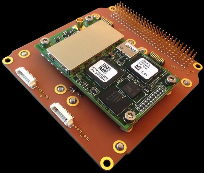
1 NanoDock DMC-3 Datasheet Daughter module carrier 4 daughterboard
2 1 Table of Contents 1 TABLE OF CONTENTS OVERVIEW HIGHLIGHTED FEATURES GPS RECEIVER BLOCK DIAGRAM CAN STACK TERMINATION RECOMMENDATION CONNECTOR PINOUT DMC-3 TOP Stack Connector H1/H X1 FSI X1-2 FSI Optional X2 - FSI P1 - Breakout Connector P2 - Breakout Connector P5-P P11- SPI to A P12 I 2 C and CAN USB Connector DMC-3 BOTTOM X3 FSI X4 - FSI P3 - Breakout Connector P4 - Breakout Connector GPS - Connection to NanoDock ABSOLUTE MAXIMUM RATINGS ELECTRICAL CHARACTERISTICS PHYSICAL CHARACTERISTICS ENVIRONMENT TESTING DISCLAIMER MECHANICAL DRAWING ADAPTION EXAMPLES EXAMPLES OF BUNDLE CONFIGURATION
3 2 Overview The GomSpace NanoDock DMC-3 is designed to carry up to four daughterboards (not included) or up to two while also providing mounting for a GPS receiver. Each daughterboard connector has communication interfaces (I 2 C and CAN) and configurable supply lines routed to the stack connector, and thus allow the DMC-3 to effectively host four subsystems. To facilitate easy tabletop debugging access to the daughterboards, a USB to 4 UARTs interface can be mounted on the DMC-3 giving the ability access UART0 on each of the daughterboards through USB. If only the two top daughterboard mounts are used, then the entire system will remain within the envelope of a single PC104 stacking height. 2.1 Highlighted Features Carrier for up to 4 daughterboards Provision for mounting a GPS receiver (in place of 2 daughterboards) Operational temperature: -40 C to +85 C Dimensions: 91.9 x 88.7 x 8.6 mm Mass: 51 grams (without 4 daughterboards) 4x 20-position FSI one-piece connector for daughterboards USB to UART console interface for easy use in lab setup PCB material: Glass/Polyimide IPC-A-610 Class 3 assembly 2.2 GPS Receiver Instead of accommodating two daughterboards on the bottom side, it is possible to mount a GPS receiver. The GPS connects to a 20-pin header that provides a permanent UART connection to the daughterboard on X1. This is designed to use a GomSpace NanoMind A3200 on-board computer to interface to the GPS. 3

4 2.3 Block diagram The block diagram below illustrates all the connections on the DMC-3. The board is designed to be very flexible allowing any daughterboard to be supplied from any of the power supply pins used in GomSpace's CubeSat products. The white dots show configurable connections. Gray dots show permanent connections. 2.4 CAN Stack Termination Recommendation GomSpace recommends having a 120 Ω termination resistor in the top and bottom of the CAN bus, to mitigate reflections. The total bus resistance should be 60 Ω. On the NanoDock DMC-3 option sheet there is an option to install a 120 Ω termination resistor. 4

5 3 Connector out The NanoDock DMC-3 is mainly a passive circuit board that provides a physical platform for the daughterboards and electrical connections to the stack connector. The only active electronics circuit is the USB to serial circuit on the bottom side of the PCB, which is powered by USB and provides a serial connection to the daughterboards. The two FSI connectors X3 and X4 can be chosen not to be installed. 3.1 DMC-3 Top Top placement of connectors. 5
6 3.1.1 Stack Connector H1/H2 The stack connector H1/H2 connects the daughterboard supplies and interfaces out to the PC104 CubeSat bus. The table below shows the used pins in the stack connector. GND, CAN and I 2 C are permanently routed to each daughterboard connector, and all supply lines can be individually configured using the option sheet. H1 H1-1 CAN Low H1-2 GPS PPS H1-3 CAN High H1-41 SDA H1-43 SCL H1-47 User supply (option) H1-48 User supply (option) H1-49 User supply (option) H1-50 User supply (option) H1-51 User supply (option) H1-52 User supply (option) H2 H2-25/26 H2-27/28 H2-29 GND H2-30 GND 5 V (option) 3,3 V (option) H2-32 GND H2-45/46 VBAT (option) X1 FSI SAMTEC FSI-110-D 1 GND 20 GND 2 GND 19 GND 3 VCC_X1 18 VCC_X1 4 VCC_X1 17 VCC_X1 5 SCL 16 AUX 1 (option VAUX) 6 SDA 15 AUX 2 (option VAUX) 7 CAN high 14 AUX 3 (option GPS PPS) 8 CAN low 13 AUX 4 9 UART0 RX 12 UART1 RX 10 UART0 TX 11 UART1 TX X1-2 FSI Optional SAMTEC FSI-110-D 10 AD3 11 AD7 * 9 AD2 12 AD6 * 8 AD1 13 AD5 7 AD0 14 AD4 6 VAUX * 15 SPIO CS2 * 5 GSSB_VCC2 * 16 SPIO CS1 4 GND 17 SPIO CS0 * 3 GSSB_VCC 18 SPIO MISO 2 I 2 C SCL2 * 19 SPIO MOSI 1 I 2 C SDA2 * 20 SPIO SCK * Not routed to any connector on the NanoDock DMC-3 6
7 3.1.4 X2 - FSI SAMTEC FSI-110-D 1 GND 20 GND 2 GND 19 GND 3 VCC_X2 18 VCC_X2 4 VCC_X2 17 VCC_X2 5 SCL 16 AUX 1 (option VAUX) 6 SDA 15 AUX 2 (option VAUX) 7 CAN high 14 AUX 3 (option GPS PPS) 8 CAN low 13 AUX 4 9 UART0 RX 12 UART1 RX 10 UART0 TX 11 UART1 TX P1 - Breakout Connector Molex PicoBlade Each daughterboard connector is associated with a breakout connector with matching numbering, so X1 is paired with P1, etc. UART0 is permanently connected to the USB to the serial circuit, see block diagram chapter UART0 RX 2 UART0 TX 3 UART1 RX 4 UART1 TX 5 AUX 1 (option VAUX) 6 AUX 2 (option VAUX) 7 AUX 3 (option GPS PPS) 8 AUX P2 - Breakout Connector Molex PicoBlade Each daughterboard connector is associated with a breakout connector with matching numbering, so X2 is paired with P2, etc. UART0 is permanently connected to the USB to the serial circuit, see block diagram chapter UART0 RX 2 UART0 TX 3 UART1 RX 4 UART1 TX 5 AUX 1 (option VAUX) 6 AUX 2 (option VAUX) 7 AUX 3 (option GPS PPS) 8 AUX 4 7
8 3.1.7 P5-P10 Molex PicoLock Headers P5-P10 provide six individual ADC inputs directly to six of the ADC inputs present on the NanoMind A3200. The tables below describe the connection to the A3200 used by each header, and the pinout for each header. Connector P5 P6 P7 P8 P9 P10 NanoMind A3200 I/O ADC 0 (PA04) ADC 1 (PA05) ADC 2 (PA06) ADC 3 (PA07) ADC 4 (PA08) ADC 5 (PA09) 1 Analog In / GPIO 2 GND Voltage division and smoothing circuitry for analog input signals is available on request. The circuit used can be seen in Figure 1. If not specified, all analog signals are directly connected to the NanoMind A3200 ADC inputs through a 0 Ω resistor at position R1, and a single 3.6 V Zener diode to prevent overvoltage to the A3200 inputs. R2 and C1 are left unpopulated. If required, custom value resistors and capacitors may be installed at positions R1, R2 and C1. Please consult with GomSpace regarding any customization to GomSpace products, as it may come at additional cost and/or a longer lead-time P11- SPI to A3200 Molex PicoLock Figure 1: Analog input voltage division and smoothing circuit P11 provides an additional SPI connection to the NanoMind A SPI0 CS1 2 SPI0 MISO 3 SPI0 MOSI 4 SPI0 SCK 5 GSSB_VCC 6 GND 8
9 3.1.9 P12 I 2 C and CAN Molex PicoLock P12 provides an additional connection to the main I 2 C and CAN buses present on the PC104 stack for peripheral payloads. The power supply VCC_PAY is configurable by the user in the hardware option sheet for the DMC-3. 1 SCL 2 SDA 3 CANL 4 CANH 5 GND 6 VCC_PAY 7 GND USB Connector Molex PicoBlade The USB connector provides USB connection to the USB to Serial circuit on the DMC-3. The pin out is shown in the table below. 1 GND 2 5 V 3 DN 4 DP 9
 6 SDA 15 AUX 2 (option VAUX) 7 CAN high 14 AUX 3 (option GPS PPS) 8 CAN low 13 AUX 4 9 UART0 RX 12 UART1 RX 10 UART0 TX 11 UART1 TX")
10 3.2 DMC-3 Bottom Bottom placement of connectors X3 FSI SAMTEC FSI-110-D 1 GND 20 GND 2 GND 19 GND 3 VCC_X3 18 VCC_X3 4 VCC_X3 17 VCC_X4 5 SCL 16 AUX 1 (option VAUX) 6 SDA 15 AUX 2 (option VAUX) 7 CAN high 14 AUX 3 (option GPS PPS) 8 CAN low 13 AUX 4 9 UART0 RX 12 UART1 RX 10 UART0 TX 11 UART1 TX 10
11 3.2.2 X4 - FSI SAMTEC FSI-110-D 1 GND 20 GND 2 GND 19 GND 3 VCC_X4 18 VCC_X4 4 VCC_X4 17 VCC_X4 5 SCL 16 AUX 1 (option VAUX) 6 SDA 15 AUX 2 (option VAUX) 7 CAN high 14 AUX 3 (option GPS PPS) 8 CAN low 13 AUX 4 9 UART0 RX 12 UART1 RX 10 UART0 TX 11 UART1 TX P3 - Breakout Connector Molex PicoBlade Each daughterboard connector is associated with a breakout connector with matching numbering, so X3 is paired with P3, etc. UART0 is permanently connected to the USB to the serial circuit, see block diagram chapter UART0 RX 2 UART0 TX 3 UART1 RX 4 UART1 TX 5 AUX 1 (option VAUX) 6 AUX 2 (option VAUX) 7 AUX 3 (option GPS PPS) 8 AUX P4 - Breakout Connector Molex PicoBlade Each daughterboard connector is associated with a breakout connector with matching numbering, so X4 is paired with P4, etc. UART0 is permanently connected to the USB to the serial circuit, see block diagram chapter UART0 RX 2 UART0 TX 3 UART1 RX 4 UART1 TX 5 AUX 1 (option VAUX) 6 AUX 2 (option VAUX) 7 AUX 3 (option GPS PPS) 8 AUX 4 11
12 3.2.5 GPS - Connection to NanoDock Samtec MMS L-DV 1 VCC_LNA (3.3 V) 2 VCC_GPS (3.3 V) 3 Not connected 4 GPS RX3 5 Not connected 6 VARF 7 Not connected 8 Not connected 9 GPS TX3 10 GND 11 GPS TX 12 GPS RX 13 GND 14 GPS TX 2 15 GPS RX 2 16 GND 17 Not connected 18 GND 19 PPS 20 Not connected The connector is intended for the NovAtel OEM615 GPS module. When choosing to prepare for a GPS module, via the options sheet, please make sure to choose a power channel for the GPS module, i.e., VCC_GPS and VCC_LNA. VCC_GPS is for the operating the GPS module and VCC_LNA is for powering the active GPS antenna. In a normal setup the VCC_GPS and VCC_LNA are connected to the same power channel. 12
13 4 Absolute maximum Ratings Stresses above those listed under Absolute Maximum Ratings may cause permanent damage to the NanoDock DMC-3. Exposure to absolute maximum rating conditions for extended periods may affect the reliability. Symbol Min. Max. Unit V_USB_5V FTDI supply voltage V T space Operating Temperature ⁰C 5 Electrical Characteristics The active electronics circuit on the NanoDock DMC-3 is the USB to serial which is powered from the USB connector. 6 Physical Characteristics Value Unit Mass without daughter boards 51 g Size Standard PC104 fit 91.9 x 88.7 x 8.6 mm 7 Environment Testing To simulate the harsh conditions of launch and space, the NanoDock DMC-3 has been exposed to a number of environment tests. For detailed information about the tests please contact GomSpace. The NanoDock DMC-3 has been in space and performed perfectly. 8 Disclaimer The information in this document is subject to change without notice and should not be construed as a commitment by GomSpace. GomSpace assumes no responsibility for any errors that may appear in this document. In no event shall GomSpace be liable for incidental or consequential damages arising from use of this document or the software and hardware described in this document. 13
14 9 Mechanical Drawing All dimensions in mm. 14


15 10 Adaption Examples NanoCom AX100 half-duplex transceiver system NanoCom AX100 dual-redundant transceiver system NanoMind A3200 Computer and NanoCom AX100 transceiver. GPS on bottom 15


16 11 Examples of bundle configuration Below is a collection of wireframe views of a fully configured DMC-3 showing dual NanoCom AX100 transceivers and a GPS receiver all on a single DMC-3. It illustrates the compactness of such a bundle. 16
NanoDock ADCS-6. Datasheet Carrier for ADCS daughterboards
 NanoDock ADCS-6 Datasheet Carrier for ADCS daughterboards 1 Table of Contents 1 TABLE OF CONTENTS... 2 2 OVERVIEW... 3 2.1 HIGHLIGHTED FEATURES... 3 2.2 BLOCK DIAGRAM... 4 2.3 EXAMPLE OF POWER SCHEME...
Datasheet Interstage unit with communication busses from OBC to I 2 C devices
 NanoUtil Interstage GSSB A, B and C Datasheet Interstage unit with communication busses from OBC to I 2 C devices 1 Table of Contents 1 TABLE OF CONTENTS... 2 2 OVERVIEW... 3 2.1 HIGHLIGHTED FEATURES...
NanoUtil TestDock. Datasheet Nano-satellite tabletop test bed
 NanoUtil TestDock Datasheet Nano-satellite tabletop test bed NanoUtil TestDock Datasheet gs-ds-nanoutil-testdock-2.2 1 Table of Contents 1 TABLE OF CONTENTS... 2 2 CHANGELOG... 3 3 OVERVIEW... 4 3.1 HIGHLIGHTED
Datasheet High performance reaction wheel for 6U and 12U nano-satellites
 gomspace.com NanoTorque GSW-600 Datasheet High performance reaction wheel for 6U and 12U nano-satellites GomSpace A/S Alfred Nobels Vej 21A 1. DK-9220 Aalborg East Denmark gomspace.com info@gomspace.com
NanoMind Z7000. Datasheet On-board CPU and FPGA for space applications
 NanoMind Z7000 Datasheet On-board CPU and FPGA for space applications 1 Table of Contents 1 TABLE OF CONTENTS... 2 2 OVERVIEW... 3 2.1 HIGHLIGHTED FEATURES... 3 2.2 BLOCK DIAGRAM... 4 2.3 FUNCTIONAL DESCRIPTION...
NanoPower BPX. Datasheet High-capacity battery pack for nano-satellites
 NanoPower BPX Datasheet High-capacity battery pack for nano-satellites 1 Table of Contents 1 TABLE OF CONTENTS... 2 2 OVERVIEW... 3 2.1 HIGHLIGHTED FEATURES... 3 2.2 CUSTOMIZATION OPTIONS... 3 2.3 MEASUREMENTS...
Datasheet On-board Computer System for mission critical space applications
 NanoMind A3200 Datasheet On-board Computer System for mission critical space applications 1 Table of Contents 1 TABLE OF CONTENTS... 2 2 OVERVIEW... 3 2.1 HIGHLIGHTED FEATURES... 3 2.2 BLOCK DIAGRAM...
CubeComputer V4.1. General purpose on-board computer. Option Sheet
 CubeComputer V4.1 General purpose on-board computer Option Sheet Page: 2 Table of Contents 1. Client Information... 3 2. Introduction... 4 3. Hardware Configuration... 5 3.1 Power supply... 5 3.2 I 2 C...
A1/B1 EB v2.0 User Manual V1.1 05/10/2017
 A1/B1 EB v2.0 User Manual V1.1 05/10/2017 Table of Contents 1. Device Overview...2 2. Electrical Characteristics...3 2.1 Test Conditions... 3 2.2 Absolute Maximum Ratings... 3 2.3 Operating Conditions...
Please refer to "4. Evaluation Board" on page 2 for more information about these steps. Figure 1. System Connections
 CP2120 EVALUATION KIT USER S GUIDE 1. Kit Contents The CP2120 Evaluation Kit contains a CP2120 evaluation board and a power supply. The following supporting documents can be downloaded from www.silabs.com:
Preliminary F40 SoC Datasheet
 GHI Electronics, LLC 501 E. Whitcomb Ave. Madison Heights, Michigan 48071 Phone: (248) 397-8856 Fax: (248) 397-8890 www.ghielectronics.com Preliminary F40 SoC Datasheet Where Hardware Meets Software GHI
CubeComputer V4.1. General purpose on-board computer. Datasheet
 CubeComputer V4.1 General purpose on-board computer Datasheet Page: 2 Table of Contents 1. System Summary... 4 1.1 Application... 4 1.2 Compatibility... 4 1.3 Heritage... 4 1.4 Features... 4 2. Functional
BANGUINO 24008C. 8-bit Processing Module Arduino-Compatible DATA SHEET
 BANGUINO 24008C 8-bit Processing Module Arduino-Compatible DATA SHEET 1. Overview Feature Highlights 68-pin device in standard PLCC68 package; three possible ways of PCB mounting DTX bus pin-compatible
MTi 1-series Development Kit
 MTi 1-series Development Kit MTi-3-DK and MTi-7-DK User Manual Document MT0513P, Revision F, 22 August 2018 Xsens Technologies B.V. Xsens North America, Inc. Pantheon 6a P.O. Box 559 7500 AN Enschede The
Arduino Diecimila Pinouts 697B B8D-A50A-61944C26074F
 mightwerk Resources for creators and innovators outs 697B1380-9797-4B8D-A50A-61944C26074F Introduction... 1 4-pin Expansion Header out... 2 6-pin ICSP Header out... 3 Map from to... 4 Map from ATmega328
Raspberry Pi board. EB080
 Raspberry Pi board www.matrixmultimedia.com EB080 Contents About this document 3 Board layout 3 General information 4 Circuit description 4 Circuit diagram 5 2 Copyright Matrix Multimedia Ltd. About this
AppNote-US2400-EVB Low Power 2.4GHz Transceiver
 US2400-EVB for IEEE 802.15.4 Standard Revision History Hardware Revision Date Description of Changes V01 / V02 Sep. 2011 Initial release V03 Dec 2011 Addition 4.1 Evaluation Board Variants and 5.3 Connector
PIXI click PID: MIKROE Weight: 28 g
 PIXI click PID: MIKROE-2817 Weight: 28 g PIXI click is equipped with MAX11300 IC from Maxim Integrated, which features Maxim Integrated's versatile, proprietary PIXI technology - it is the industry's first
MTi 1-series Development Kit
 MTi 1-series Development Kit MTi-3-DK and MTi-7-DK User Manual Document MT0513P, Revision D, 24 March 2018 Xsens Technologies B.V. Xsens North America, Inc. Pantheon 6a P.O. Box 559 7500 AN Enschede The
AARDVARK. Level Shifter Board. Level Shifter Board. Datasheet v1.00 February 15, 2008 I 2 C/SPI. Features
 Level Shifter Board AARDVARK I 2 C/SPI Features Level shifting of I 2 C, SPI, and MDIO signals from 1.2 V to 3.3 V I 2 C speeds of up to 800 khz SPI and MDIO speeds of up to 20 MHz Powering downstream
Adafruit Terminal Block Breakout FeatherWing
 Adafruit Terminal Block Breakout FeatherWing Created by lady ada Last updated on 2017-01-04 04:53:26 AM UTC Guide Contents Guide Contents Overview Pinouts Assembly Downloads Datasheets & Files Schematic
6LoWPAN Development Platform Saker Manual
 6LoWPAN Development Platform Saker Manual WEPTECH elektronik GmbH Page 1 of 19 V.1.0.1 1. Table of Content 1. General information... 4 1.1 1.2 1.3 1.4 1.5 Copyright protection... 4 Warranty information...
Pridgen Vermeer Robotics Xmega128 Manual
 Features: 12x PWM signals with 5V supply 8x A/D Inputs with 3.3V supply 2x RS 232 Terminals 1x SPI Interface 4x 8-bit Digital IO ports 3.3V Power Bus LCD Header (4-bit mode) Smart Power Connecter Power
MINITRONICS v1.0 DATASHEET
 MINITRONICS v. DATASHEET Author Bart Meijer Date 2th of April 23 Document version. ReprapWorld.com PRODUCT OVERVIEW Minitronics is the latest development of ReprapWorld.com. It's designed to be an easy
HZX N03 Bluetooth 4.0 Low Energy Module Datasheet
 HZX-51822-16N03 Bluetooth 4.0 Low Energy Module Datasheet SHEN ZHEN HUAZHIXIN TECHNOLOGY LTD 2017.7 NAME : Bluetooth 4.0 Low Energy Module MODEL NO. : HZX-51822-16N03 VERSION : V1.0 1.Revision History
G80 SoC Datasheet. Where Hardware Meets Software
 GHI Electronics, LLC 501 E. Whitcomb Ave. Madison Heights, Michigan 48071 Phone: (248) 397-8856 Fax: (248) 397-8890 www.ghielectronics.com G80 SoC Datasheet Where Hardware Meets Software GHI Electronics,
USER GUIDE. ATWINC1500 Xplained Pro. Preface
 USER GUIDE ATWINC1500 Xplained Pro Preface Atmel ATWINC1500 Xplained Pro is an extension board to the Atmel Xplained Pro evaluation platform. The extension board allows to evaluate the Atmel ATWINC1510/1500
SKB360I Bluetooth 4.0 Low Energy Module Datasheet
 SKB360I Bluetooth 4.0 Low Energy Module Datasheet Name: Bluetooth 4.0 Low Energy Module Model No.: SKB360I Version: V1.01 Revision History: Revision Description Approved Date V1.01 Initial Release Hogan
Skywire BeagleBone Black Cape Data Sheet
 Skywire BeagleBone Black Cape Data Sheet NimbeLink Corp Updated: January 2018 PN 30122 rev 2 NimbeLink Corp. 2016. All rights reserved. 1 Table of Contents Table of Contents 2 Introduction 3 Overview 3
I/O1 Xplained Pro. Preface. Atmel MCUs USER GUIDE
 Atmel MCUs I/O1 Xplained Pro USER GUIDE Preface Atmel I/O1 Xplained Pro is an extension board to the Atmel Xplained Pro evaluation platform. I/O1 Xplained Pro is designed to give a wide variety of functionality
A1/B1 Baseboard User Manual
 A1/B1 Baseboard User Manual v1.2 Table of contents Preface...2 1 Introduction...3 1.1 General description... 3 1.2 Features... 3 1.3 Product overview... 4 1.4 Outputs and headers... 5 2 Electrical Characteristics...7
PCB-STM32-F3U. Development baseboard for the STMicro Discovery-F3 module (STMicro part# STM32F3DISCOVERY)
") PCB-STM32-F3U Development baseboard for the STMicro Discovery-F3 module (STMicro part# STM32F3DISCOVERY) Part Number: PCB-STM32-F3U (unpopulated PCB with Discovery module sockets, no other parts) STM32-F3U
PCB-STM32-F3U Development baseboard for the STMicro Discovery-F3 module (STMicro part# STM32F3DISCOVERY) Part Number: PCB-STM32-F3U (unpopulated PCB with Discovery module sockets, no other parts) STM32-F3U
Description. Overview. Features S90-MTM-DEV-2. MTM Development Board 2.0 Datasheet
 Overview The Acroname Development Board 2.0 (-DEV-2), part of Acroname s (Manufacturing Test Module) product series, is a connectivity solution designed for development or integration to wire-based testers.
ZSSC4151 Evaluation Kit Hardware Manual
 Important Notes Restrictions in Use IDT s ZSSC4151 SSC Evaluation Kit, consisting of the SSC Communication Board (SSC CB), ZSSC415x/6x/7x Evaluation Board (SSC EB), Sensor Replacement Board (SSC RB), and
EPS USER MANUAL. Electrical Power System (EPS)
") EPS USER MANUAL Electrical Power System (EPS) 1 Change Log... 3 2 Acronyms List... 4 3 Highlighted Features... 5 4 System Description... 5 5 Block Diagram... 11 6 Connector Pinout... 11 Connectors Location...
EPS USER MANUAL Electrical Power System (EPS) 1 Change Log... 3 2 Acronyms List... 4 3 Highlighted Features... 5 4 System Description... 5 5 Block Diagram... 11 6 Connector Pinout... 11 Connectors Location...
Logic Way GmbH, DIMM-CPU-CB09.odt
 Logic Way GmbH, http://www.logicway.de 2010-12-17 DIMM-CPU-CB 09 Breakout and interface board for vehicle application with 2xCAN, 2x2.4GHz IEEE802.15.4 radio, GPS receiver, GSM/GPRS modem, RTC, SD card,
AT02667: XMEGA-E5 Xplained Hardware User's Guide. Features. Description. AVR XMEGA Microcontrollers APPLICATION NOTE
 AVR XMEGA Microcontrollers AT02667: XMEGA-E5 Xplained Hardware User's Guide APPLICATION NOTE Features Atmel AVR ATxmega32E5 microcontroller OLED display with 128 32 pixels resolution Ambient light sensor
Ant6. 6 Channel H Bridge 3-Axis Bipolar Stepper Motor Controller. Technical Reference Manual PCB Rev 1.0.
 Ant6 6 Channel H Bridge 3-Axis Bipolar Stepper Motor Controller Technical Reference Manual PCB Rev 1.0 www.soc-robotics.com Copyright 2008. SOC Robotics, Inc. 1 Manual Rev 0.9 Warranty Statement SOC Robotics
GAUSS OBC ABACUS 2017
 [] Table of contents Table of contents... 1 1. Introduction... 3 1.1. ABACUS Features... 3 1.2. Block Diagram... 6 2. Pinouts... 7 3. Inertial Measurement Unit Details... 10 3.1. Orientation of Axes...
UIB-PC104. User Interface Board. Product manual. 2007, ingenia-cat S.L. 03/08/07 Version 2.0
 User Interface Board 0/0/0 Version.0 00, ingenia-cat S.L. Copyright and trademarks Copyright 00 ingenia-cat, S.L. Microchip and dspic are registered marks of Microchip in the USA and other countries. Scope
Pmod modules are powered by the host via the interface s power and ground pins.
 1300 Henley Court Pullman, WA 99163 509.334.6306 www.store. digilent.com Digilent Pmod Interface Specification 1.2.0 Revised October 5, 2017 1 Introduction The Digilent Pmod interface is used to connect
This manual provides information for the final user application developer on how to use SPC57S-Discovery microcontroller evaluation board.
 User manual SPC570S-DISP: Discovery+ Evaluation Board Introduction This manual provides information for the final user application developer on how to use SPC57S-Discovery microcontroller evaluation board.
FRDM-KL26Z User s Guide
 Freescale Semiconductor User s Guide Doc Number: FRDMKL26ZUG Rev. 0, 10/2013 FRDM-KL26Z User s Guide by Freescale Semiconductor, Inc. 1 Overview The Freescale Freedom development platform is a set of software
GAUSS: ABACUS User Selectable Options Sheet [ABACUS2017_ ]
![GAUSS: ABACUS User Selectable Options Sheet [ABACUS2017_ ]](/thumbs/77/74793890.jpg "GAUSS: ABACUS User Selectable Options Sheet [ABACUS2017_ ]") [ ] Table of contents Table of contents... 2 Acronyms... 3 1. Introduction... 4 2. Blocks Diagram, Connectors and Pinout overview... 5 3. Options Sheet Selection Guide... 6 3.1. GPIO Expander... 6 3.2.
[ ] Table of contents Table of contents... 2 Acronyms... 3 1. Introduction... 4 2. Blocks Diagram, Connectors and Pinout overview... 5 3. Options Sheet Selection Guide... 6 3.1. GPIO Expander... 6 3.2.
RS485 3 click. How does it work? PID: MIKROE-2821
 RS485 3 click PID: MIKROE-2821 RS485 3 click is an RS422/485 transceiver Click board, which can be used as an interface between the TTL level UART and the RS422/485 communication bus. It features a full-duplex
ootbrobotics.com Electronics and Robotics LLC
 2 Warning Before Proceeding... 4 On Board Features... 5 Smart Power Switching... 5 Indicators... 5 Power Indicators... 5 Status LED... 5 RGB Indicator... 5 External Power (EXP) Indicator... 6 USB Serial
HVP-MC56F82748 User s Guide
 Freescale Semiconductor, Inc. User s Guide Document Number: HVPMC56F82748UG Rev. 0, 12/2014 HVP-MC56F82748 User s Guide by: Ivan Lovas 1 High voltage controller cards overview This document supports the
USER GUIDE. Atmel OLED1 Xplained Pro. Preface
 USER GUIDE Atmel OLED1 Xplained Pro Preface Atmel OLED1 Xplained Pro is an extension board to the Atmel Xplained Pro evaluation platform. The board enables the user to experiment with user interface applications
PlainDAC. PolyVection. embedded audio solutions DATASHEET. PlainDAC chip on module page
 PlainDAC DATASHEET Audiophile digital-to-analog converter module with I2S input Document revision 1.0 July 2016 1 1 FEATURES Audiophile I2S DAC module Texas Instruments PCM5100 or PCM5121 or PCM5142 Two
Adafruit USB Power Gauge Mini-Kit
 Adafruit USB Power Gauge Mini-Kit Created by Bill Earl Last updated on 2017-07-14 11:55:04 PM UTC Guide Contents Guide Contents Overview Assembly Basic Assembly Solder the female connector. Solder the
Real-Time Embedded Systems. CpE-450 Spring 06
 Real-Time Embedded Systems CpE-450 Spring 06 Class 5 Bruce McNair bmcnair@stevens.edu 5-1/42 Interfacing to Embedded Systems Distance 100 m 10 m 1 m 100 cm 10 cm "Transmission line" capacitance ( C) Distance
Goal: We want to build an autonomous vehicle (robot)
") Goal: We want to build an autonomous vehicle (robot) This means it will have to think for itself, its going to need a brain Our robot s brain will be a tiny computer called a microcontroller Specifically
Goal: We want to build an autonomous vehicle (robot) This means it will have to think for itself, its going to need a brain Our robot s brain will be a tiny computer called a microcontroller Specifically
USER MANUAL FOR HARDWARE REV
 PI-REPEATER-2X 1. WELCOME 2. CONTENTS PAGE 1 3. GETTING STARTED There are many features built into this little board that you should be aware of as they can easily be missed when setting up the hardware
RFID Reader Board 13.56MHz RFID Transceiver MLX90132
 Table of Contents 1. General Description... 2 1.1 Connector X1 (SPI/ UART Communication)... 2 2. MLX90132 Pin Definitions & Descriptions... 3 2.1 MLX90132 simplified Block Diagram... 3 3. RFID90132 Circuit
um-fpu64 Floating Point Coprocessor 28-pin Breakout Board Introduction Bare um-fpu64 28-pin Breakout Board
 Floating Point Coprocessor Breakout Board Introduction The breakout board has all of the required connections, and provides access to all um- FPU64 pins. It can be used as a development board or for permanently
USB UART 4 click PID: MIKROE Weight: 23 g
 USB UART 4 click PID: MIKROE-2810 Weight: 23 g USB UART 4 click features well-known FT232RL USB-to-UART interface module from FDTI. It provides USB to asynchronous serial data transfer interface, allowing
Sample board for USB DEVELOPPER KIT
 Sample boards supporting several pressure modules including: - MS45xx family (on request only) - MS5536 - MS5540 / 5541 - MS5561 - MS5607 / 5611 - MS5637 - MS5803 - MS5805 - MS5806 2 connectors on board:
SBD WARRIOR DATA SHEET
 SBD WARRIOR DATA SHEET www.satelligent.ca v1.3 Features Controller for Iridium 9603 SBD transceiver 48 channel SiRFstarIV chipset based GPS Serial interface for 3rd party equipment or PC control Wide supply
HVP-KV31F120M User s Guide
 Freescale Semiconductor, Inc. User s Guide Document Number: HVPKV31F120MUG Rev. 0, 12/2014 HVP-KV31F120M User s Guide by: Ivan Lovas 1 High voltage controller card HVP-KV31F120M This document supports
USB Debug Adapter. Power USB DEBUG ADAPTER. Silicon Laboratories. Stop. Run. Figure 1. Hardware Setup using a USB Debug Adapter
 C8051F38X DEVELOPMENT KIT USER S GUIDE 1. Kit Contents The C8051F38x Development Kit contains the following items: C8051F380 Target Board C8051Fxxx Development Kit Quick-start Guide Silicon Laboratories
LCD-1 Peripheral Board Technical Manual
 LCD-1 Peripheral Board Technical Manual Document Revision: 1.03 Date: 22 April, 2003 BiPOM Electronics, Inc. 16301 Blue Ridge Road, Missouri City, Texas 77489 Telephone: 1-713-283-9970. Fax: Fax: 1-281-416-2806
Ethernet1 Xplained Pro
 Ethernet1 Xplained Pro Part Number: ATETHERNET1-XPRO The Atmel Ethernet1 Xplained Pro is an extension board to the Atmel Xplained Pro evaluation platform. The board enables the user to experiment with
1.6inch SPI Module user manual
 1.6inch SPI Module user manual www.lcdwiki.com 1 / 10 Rev1.0 Product Description The 1.6 module is tested using the ESP8266MOD D1 Mini development board, Both the test program and the dependent libraries
Prototyping Module Datasheet
 Prototyping Module Datasheet Part Numbers: MPROTO100 rev 002 Zenseio LLC Updated: September 2016 Table of Contents Table of Contents Functional description PROTOTYPING MODULE OVERVIEW FEATURES BLOCK DIAGRAM
ATWINC3400-XPRO. Preface. SmartConnect USER GUIDE
 SmartConnect ATWINC3400-XPRO USER GUIDE Preface Atmel ATWINC3400-XPRO is an extension board to evaluate the performance of ATWINC3400-MR210CA, an IEEE 802.11 b/g/n RF/ Baseband/MAC Link Controller with
General-Purpose Microcontroller Module 12a Hardware Reference Release 1.4a (October 11, 2017)
") General-Purpose Microcontroller Module 12a Hardware Reference 1 General-Purpose Microcontroller Module 12a Hardware Reference Release 1.4a (October 11, 2017) Purpose: General-purpose platform to accommodate
General-Purpose Microcontroller Module 12a Hardware Reference 1 General-Purpose Microcontroller Module 12a Hardware Reference Release 1.4a (October 11, 2017) Purpose: General-purpose platform to accommodate
Neo900 Hackerbus PRELIMINARY SUBJECT TO CHANGE WITHOUT FURTHER NOTICE
 Neo900 Hackerbus PRELIMINARY SUBJECT TO CHANGE WITHOUT FURTHER NOTICE Jörg Reisenweber, Werner Almesberger February 25, 2015 The Hackerbus is an interface that allows user-provided circuits to connect
BB-303 Manual Baseboard for TMCM-303
 BB-303 Manual Baseboard for TMCM-303 Trinamic Motion Control GmbH & Co. KG Sternstraße 67 D 20357 Hamburg, Germany http://www.trinamic.com BB-303 Manual (V1.04 / Jul 9th, 2007) 2 Contents 1 Features...
eip-24/100 Embedded TCP/IP 10/100-BaseT Network Module Features Description Applications
 Embedded TCP/IP 10/100-BaseT Network Module Features 16-bit Microcontroller with Enhanced Flash program memory and static RAM data memory On board 10/100Mbps Ethernet controller, and RJ45 jack for network
Ultratronics v1.0 DATASHEET
 Ultratronics v1.0 DATASHEET Author Bart Meijer Date November 21 st, 2017 Document version 1.2 Ultratronics Datasheet Reprapworld.com 1 PRODUCT OVERVIEW Ultratronics is the latest development in 3D printer
ILI2511. ILI2511 Single Chip Capacitive Touch Sensor Controller. Specification ILI TECHNOLOGY CORP. Version: V1.4. Date: 2018/7/5
 Single Chip Capacitive Touch Sensor Controller Specification Version: V1.4 Date: 2018/7/5 ILI TECHNOLOGY CORP. 8F., No.1, Taiyuan 2 nd St., Zhubei City, Hsinchu County 302, Taiwan (R.O.C.) Tel.886-3-5600099;
Almond - Datasheet November 2015
 Robotic Hand Development Board Features 6 Bidirectional Motor control USB Programming (with Bootloader) Arduino IDE Compatible Compatible with Firgelli PQ12 -P Actuators Atmel Atmega2560 Microcontroller
PIC Serial Peripheral Interface (SPI) to Digital Pot
 to Digital Pot") Name Lab Section PIC Serial Peripheral Interface (SPI) to Digital Pot Lab 7 Introduction: SPI is a popular synchronous serial communication protocol that allows ICs to communicate over short distances
Name Lab Section PIC Serial Peripheral Interface (SPI) to Digital Pot Lab 7 Introduction: SPI is a popular synchronous serial communication protocol that allows ICs to communicate over short distances
ZigBee Compliant Platform 2.4G RF Low Power Transceiver Module for IEEE Standard. DATA SHEET Version B
 ZMD400-A01 ZigBee Compliant Platform 2.4G RF Low Power Transceiver Module for IEEE 802.15.4 Standard DATA SHEET Version B Quan International Co., Ltd., ZMD400 Features Fully compliant 802.15.4 Standard
Product description Rev. 3 11/06/14
 EZ863-2G - GNSS Product description Rev. 3 11/06/14 1 Table of Contents 1. Overview... 4 2. General Description... 4 2.1 Dimensions... 4 2.2 Weight... 4 2.2 Installation... 5 2.3 Casing material... 6 2.4
Product Specification
 Product Specification Features Amp ed RF, Inc. Description 15mm x 27mm The added class 1 power, +18dBm, of the BT-11, gives this module one of the best ranges in the industry. It s completely pin compatible
ConnectCore for i.mx6ul Starter Board. Hardware Reference Manual
 ConnectCore for i.mx6ul Starter Board Hardware Reference Manual Revision history 90001520 Revision Date Description 01 October 2016 Alpha release Trademarks and copyright Digi, Digi International, and
EVAcharge SE - Datasheet
 EVAcharge SE - Datasheet Datasheet (valid for board revision V0R4 or higher) Document history Revision 1.0 2013-10-10 Initial release 1.1 2013-11-06 Typo corrections 1.2 2014-05-13 Removed serial IF 1.3
Four-Channel Universal Analog Input Using the MAX11270
 Four-Channel Universal Analog Input Using the MAX70 MAXREFDES5 Introduction The MAXREFDES5 is a four-channel universal analog input that measures voltage or current signals. Each channel can be configured
BV511 Hardware Guide ByVac ByVac Revision 1.0
 BV511 Hardware Guide ByVac ByVac 2007 www.byvac.co.uk Revision 1.0 ByVac 1 Copyright in this work is vested in ByVac and the document is issued in confidence for the purpose only for which it is supplied.
RiseUp RU8-DP-DV Series 19mm Stack Height Final Inch Designs in PCI Express Applications. Revision Date: March 18, 2005
 RiseUp RU8-DP-DV Series 19mm Stack Height Final Inch Designs in PCI Express Applications Revision Date: March 18, 2005 Copyrights and Trademarks Copyright 2005 Samtec, Inc. Developed in conjunction with
SH1030 Rev Introduction. Ultra low power DASH7 Arduino Shield Modem. Applications. Description. 868 MHz. Features
 SH1030 Rev. 1.2 Applications Wireless sensor network Data acquisition equipment Security systems Industrial monitor and control Internet of things (IoT) Ultra low power DASH7 Arduino Shield Modem 868 MHz
Part Number: PCB-STM32-F4B1 (unpopulated PCB with Discovery module sockets, no other parts) STM32-F4B1 (assembled board, not presently available)
 STM32-F4B1 (assembled board, not presently available)") PCB-STM32-F4B1 Development baseboard for the STMicro Discovery-F4 module (STMicro part# STM32F4DISCOVERY) PCB Rev 1.00 shown. PCB Rev 1.20 has on-board RS232 drivers. Part Number: PCB-STM32-F4B1 (unpopulated
PCB-STM32-F4B1 Development baseboard for the STMicro Discovery-F4 module (STMicro part# STM32F4DISCOVERY) PCB Rev 1.00 shown. PCB Rev 1.20 has on-board RS232 drivers. Part Number: PCB-STM32-F4B1 (unpopulated
Evaluation Board for CS3308. Description CS Channel. Digitally Controlled Analog Volume Control. PC or External Serial Control Input
 Evaluation Board for CS3308 Features Description Single-ended Analog Inputs Single-ended Analog Outputs Supports AC and DC-Coupled Analog I/O Flexible Serial Control I/O Headers Serial Control Input Header
Voltage Regulator Board User Guide
 Embedded Systems for Space Applications Voltage Regulator Board User Guide David Hoskins Josh Chapman University of Tennessee at Chattanooga 4/23/17 Overview The objective of this project is to provide
Chapter 2 ICB Architecture Chapter 3 Board Components GPIO Interface RS-232 Interface RS-485 Interface...
 1 CONTENTS Chapter 1 Introduction... 3 1.1 Features...3 1.2 About the Kit...4 1.3 Getting Help...5 Chapter 2 ICB Architecture... 6 2.1 Layout and Components...6 2.2 Block Diagram of the ICB...7 Chapter
Arduino Uno. Arduino Uno R3 Front. Arduino Uno R2 Front
 Arduino Uno Arduino Uno R3 Front Arduino Uno R2 Front Arduino Uno SMD Arduino Uno R3 Back Arduino Uno Front Arduino Uno Back Overview The Arduino Uno is a microcontroller board based on the ATmega328 (datasheet).
CF Plug-In. Evaluation Board User Guide. Bulletin Revision Date
 CF Plug-In Evaluation Board User Guide Bulletin Revision Date JA03-EBUG 00 06 Dec 2017 Table of Contents I. Introduction------------------------------------------------------------------------- 2 Scope
VLSI AppNote: VSx053 Simple DSP Board
 : VSx053 Simple DSP Board Description This document describes the VS1053 / VS8053 Simple DPS Board and the VSx053 Simple DSP Host Board. Schematics, layouts and pinouts of both cards are included. The
802.11b/g/n IOT Module
 802.11b/g/n Industrial-Grade IOT Module, Qualcomm Atheros QCA4010, 1T1R Feature Standard: 802.11b/g/n Host Interface: UART, SPI/SDIO, I2C/I2S, USB, ADC Chipset: Qualcomm Atheros QCA4010 Antenna: PCB Printed
Atmel ATMXT143E touchscreen controller Capacitive touch ITO 320 x 240 pixel LCD display with SPI interface LED backlight
 APPLICATION NOTE Features Atmel AVR32936: mxt143e Xplained Hardware Users Guide Atmel maxtouch Touchscreen Controller 2.8 inch mxt143e LCD display module from Precision Design Associates (PDA) Atmel ATMXT143E
USB3319. Hi-Speed USB Transceiver with 1.8V ULPI Interface - 13MHz Reference Clock PRODUCT FEATURES. Applications. Data Brief
 USB3319 Hi-Speed USB Transceiver with 1.8V ULPI Interface - 13MHz Reference Clock PRODUCT FEATURES Data Brief USB-IF Hi-Speed compliant to the Universal Serial Bus Specification Rev 2.0 Interface compliant
ESPino - Specifications
 ESPino - Specifications Summary Microcontroller ESP8266 (32-bit RISC) WiFi 802.11 (station, access point, P2P) Operating Voltage 3.3V Input Voltage 4.4-15V Digital I/O Pins 9 Analog Input Pins 1 (10-bit
USB HD Audio/Video Codec Model 2263 Hardware Manual Ver October 2013
 USB HD Audio/Video Codec Model 2263 Hardware Manual Ver.1.0.1 October 2013 Table of Contents LIMITED WARRANTY...3 SPECIAL HANDLING INSTRUCTIONS...4 INTRODUCTION...5 SYSTEM REQUIREMENTS...5 BLOCK DIAGRAM...6
APPLICATION NOTE. Atmel AT01080: XMEGA E Schematic Checklist. Atmel AVR XMEGA E. Features. Introduction
 APPLICATION NOTE Atmel AT01080: XMEGA E Schematic Checklist Atmel AVR XMEGA E Features Power supplies Reset circuit Clocks and crystal oscillators PDI TWI Introduction This application note describes a
AT88CK101 HARDWARE USER GUIDE. Atmel CryptoAuthentication Development Kit. Atmel CryptoAuthentication AT88CK101 Daughterboard
 AT88CK101 Atmel CryptoAuthentication Development Kit HARDWARE USER GUIDE Atmel CryptoAuthentication AT88CK101 Daughterboard Introduction The Atmel CryptoAuthentication AT88CK101 is a daughterboard that
MultiConnect OCG. Break-Out Board. Developer s Guide
 MultiConnect OCG Break-Out Board Developer s Guide Copyright and Technical Support MultiConnect OCG Break-Out Board Developer s Guide Models: MTOCG-BOB S000518A, Version A Copyright This publication may
Modtronix Engineering Modular Electronic Solutions SBC28DC. Single board computer for 28 pin DIP PICs
 Modtronix Engineering Modular Electronic Solutions Single board computer for 28 pin DIP PICs Table of Contents 1 Introduction...2 2 Features...4 3 Expansion Connectors...5 3.1 Daughter Board Connectors...5
Case USB-MUX-4C2L 4 CAN - 2 LIN/ISO
 Case USB-MUX-4C2L 4 CAN - 2 LIN/ISO Installation guide Document n. 054114-04 Published 08/07/2005 ANNECY ELECTRONIQUE Z.A. Les Marais 74410 St JORIOZ Phone : +33 (0) 450 68 90 65 Fax: +33 (0) 450 68 58
AIS CUBE 2.83 AMOLED DISPLAY. Datasheet & Application Note Rev.A July 2010 Release
 AIS CUBE 2.83 AMOLED DISPLAY Datasheet & Application Note Rev.A July 2010 Release TECHNICAL OVERVIEW Diagonal Size 2.83 Driving Mode Active Matrix Colour Mode 16bit RGB 5/6/5262K Colours Interface Mode