Short Introduction to DCS, JCOP Framework, PVSS. PVSS Architecture and Concept. JCOP Framework concepts and tools.
|
|
|
- Felicia Bradley
- 5 years ago
- Views:
Transcription


1 Hassan Shahzad, NCP
2 Contents Short Introduction to DCS, JCOP Framework, PVSS and FSM. PVSS Architecture and Concept. JCOP Framework concepts and tools. CMS Endcap RPC DCS. 2
3 What is DCS DCS stands for Detector Control System. In all large experiments a control system is required which controls and monitors the experimental hardware and takes necessary actions to avoid failure. At LHC, to control and monitor the installed detectors at experimental areas, an intelligent and powerful DCS is used to assure the reliable and safe operation of the electronics. 3
4 Layers of DCS at CERN Supervisory Application JCOP FW (Supervisory) PVSS FSM, DB, etc. Supervision PC (Windows, Linux) OPC, PVSS Comms, DIM, DIP OPC, PVSS Comms, DIM, DIP Communication FE Application Device Driver Commercial Devices(CAEN) FE Application UNICOS FW PLC Other Systems Front-end 4
5 What is JCOP? JCOP stands for Joint COntrols Project. Grouping of representatives from the 4 big Large Hadron Collider (LHC) experiments. Aims to reduce the overall manpower cost required to produce and run the experiment control systems. 5
6 What is PVSS? The Supervisory Control And Data Acquisition (SCADA) system chosen by JCOP. JCOP chose PVSS (Prozeßvisualisierungs und Steuerungs system) as LHC control system software after extensive evaluation. It is a commercial product from ETM, Austria. Since then, PVSS has been widely adopted across CERN. PVSS is a TOOL to build control systems, it is not a control system! 6
7 7

8 What is PVSS (cont.)? PVSS has capabilities for: Device Description Data Points, and Data Point elements Device Access OPC, Drivers etc Alarm Handling Generation, Masking, etc Alarm Display, Filtering, Summarising Archiving, Trending, Logging User Interface Builder Access Control 8
9 Cont.. The device data in the PVSS database is structured as, so called, Data Points (DP) of a pre defined Data Point Type (DPT). PVSS allows devices to be modeled using these DPTs/DPs. DPTs are similar to Classes in Object Oriented terminology. DPs are similar to Objects instantiated from a Class in Object Oriented terminology. 9
10 What is PVSS not? PVSS II does not have tools specifically for: Abstract behaviour modelling Finite State Machines Automation & Error Recovery Expert System But FSM (SMI++) does 10
 product which was developed for the DELPHI experiment.")
11 What is FSM? Finite State Machine (FSM) Abstract representation of your experiment. What state is it in? Is it taking data? Is it in standby? Is it broken? Is it switched off? What triggers it to move from one of these states to another? JCOP chose the State Management Interface (SMI++) product which was developed for the DELPHI experiment. SMI++ is vital for controlling & recovering large experiments 11

12 What is JCOP Framework? A layer of software components These components are produced in collaboration. All these components can work together and make the job easy. It is very useful for large PVSS projects. 12

13 Experiments using PVSS LHC Experiments All LHC experiments have projects Has been used for many years in test beams Fixed Target Experiments COMPASS Helped in framework development Now in production HARP, NA60, NA48/NA
14 PVSS Architecture and Concept. 14
15 PVSS Architecture PVSS has a highly distributed architecture. A PVSS application is composed of several processes, in PVSS nomenclature: Managers. These Managers communicate via a PVSS-specific protocol over TCP/IP. Managers subscribe to data and this is then only sent on change by the Event Manager, which is the heart of the system. 15
16 A Typical PVSS System UIM UIM UIM User Interface Layer CTRL API Processing Layer DM EV Communication and Memory Layer D D D Driver Layer 16
17 PVSS Managers Overview The Event Manager (EVM) is responsible for all communications. It receives data from Drivers (D) and sends it to the Database Manager to be stored in the data base. However, it maintains the process image in memory, i.e. the current value of all the data. It also ensures the distribution of data to all Managers which have subscribed to this data. The DataBase Manager (DBM) provides the interface to the (run-time) data base. 17
18 Cont.. User Interface Managers (UIM) can get device data from the database, or send data to the database. Ctrl Managers (Ctrl) provide for any data processing as background processes, by running a scripting language. This language is like C with extensions. API Managers (API) Allow users to write their own programs in C++ using a PVSS API (Application Programming Interface) to access the data in the database. Drivers (D) Provide the interface to the devices to be controlled. These can be PVSS provided drivers or user-made drivers. 18
19 Types of PVSS Systems A PVSS System is an application containing one data base manager and one event manager and any number of drivers, user interfaces, etc. PVSS Managers can run on Windows or Linux and they can all run in the same machine or be distributed across different machines (including mixed Windows and Linux environments). When the managers of one system run distributed across different machines this is called a PVSS Scattered System. 19
20 Cont.. PVSS can provide control for very large applications, in which case one PVSS system would not be enough. In this case a PVSS Distributed System can be used. As shown in a figure, distributed system is built by adding a Distribution Manager (Dist) to each system and connecting them together. Hundreds of systems can be connected in this way. 20
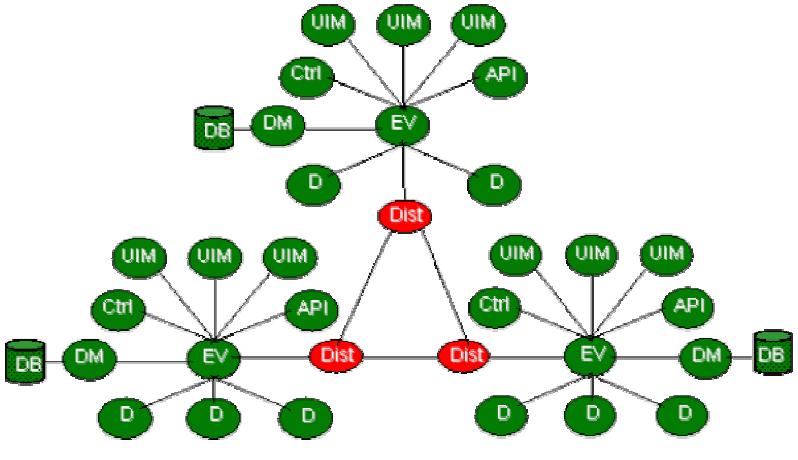
21 Distributed System 21
22 Distributed System System 1 System 2 Operator 1 UI Userinterface Runtime UI Userinterface Runtime Operator 2 Server 1 Server 2 System 3 Single Machine Station CTRL Controlmanager DB Database- Manager UI Userinterface Runtime EV Event- Manager D Driver DIST Distribution Manager Operator 1 UI Userinterface Runtime Server CTRL Control- Manager DB Database- Manager EV Event- Manager D Driver Operator 2 UI Userinterface Runtime DIST Distribution Manager CTRL Control- Manager DB Database- Manager EV Event- Manager D Driver REDU Redundancy Manager DIST Distribution Manager REDU Redundancy Manager DIST Distribution Manager EV Event- Manager D Driver CTRL Control- Manager DB Database- Manager Local Area Network TCP October 23, 2009 Hassan Shahzad, NCP 22
23 Distributed System Distribution Manager provides the interface between systems Event driven communication leads to low network load Only requested data is transferred Integrated connection monitoring Interconnected 130 systems at CERN. 23
24 JCOP Framework concepts and tools. 24
25 Aims of the JCOP Framework Reduce the development effort Reuse of components Hide complexity. Facilitate the integration. Reduce resources for maintenance Homogeneous control system. Easy operation and maintenance. Provide a higher layer of abstraction reduce knowledge of tools interface for non experts Customize & Extend industrial components Modular/Extensible As simple as possible Development driven by the JCOP FW Working Group. 25
26 What is it (not)? 26
27 DCS Architecture Supervisory Application JCOP FW (Supervisory) PVSS FSM, DB, etc. Supervision PC (Windows, Linux) OPC, PVSS Comms, DIM, DIP OPC, PVSS Comms, DIM, DIP Communication FE Application Device Driver Commercial Devices(CAEN) FE Application UNICOS FW PLC Other Systems Front-end 27

28 Tools Provided by JCOP Framework Device Editor and Navigator (DEN) Main user interface to the Framework. Configuring devices, users login. High level view of experiment Includes FSMs Fw Tree View Provides the Tree view of whole project. fwgeneral: Exception handling Panels to give messages to users Help system One html file for every panel. For library routines the help text is within the code itself. 28
29 Cont.. Fw Config Library Hide complexity of PVSS configs Optimized functions for mass configuration Exceptions are handled Component Installation Tool Trending Greatly simplifies PVSS trends. Configuration DB Fw definitions stored in Oracle. Static definitions (DEN configuration) Recipes (Values, eg for physics / comics / shutdown states 29
30 Cont.. Mass Configuration Easy configuration of many channels with alerts, settings etc. Access control Hide complexity of PVSS access control! Defines privilege levels and role groups (operator, expert etc.) 30
31 31

32 Brief Introduction to CMS and RPC CMS (Compact Muon Solenoid) is one of the main experiment sight at LHC. RPCs are the dedicated detectors used for the first level muon trigger of CMS. Good performance of RPC is essential in assigning the muon to the right bunch crossing at the LHC. The CMS Experiment 32
33 RPC DCS The RPC DCS has two sub systems: RPC Barrel and RPC Endcap. RPC Barrel DCS is prepared by Italian Group. RPC Endcap DCS is prepared by NCP HEP Group in coordination with Barrel DCS group expert. The Endcap RPC system of CMS detector comprises of 432 double gap chambers. The correct and safe operation of the RPC system requires a sophisticated and complex online Detector Control System (DCS), able to monitor and control the RPC hardware devices. 33
34 RPC DCS The RPC DCS system has to assure the safe and correct operation of the sub detectors during the entire CMS life time (more than 10 years), detect abnormal and harmful situations and take protective and automatic actions to minimize consequential damages. 34
35 RPC ENDCAP DCS The RPC Endcap DCS is subdivided into several subsystems: High Voltage (HV), Low Voltage (LV), Environmental Sensors(humidity and temperature ), Gas, Cooling systems. NCP EHEP Group had designed and prepared the software applications for the control and monitoring of the HV, LV systems and environmental sensors. All information is monitored and shared through the Central DCS. Cooling and Gas systems are instead developed centrally by CMS DCS Group. 35
 and two LV channels.")
36 The RPC Endcap Power system: high voltage and low voltage Large part of the RPC Endcap power system is located close to the detector and in particular inside the racks placed on the balconies around the Endcap wheel. Every RPC chamber has been equipped with two independent HV channels (one per gap) and two LV channels. In addition four LV channels are needed to supply each Link Boards Box (LBB), aimed to collect data from each chamber, synchronize and send them to trigger and readout chain in control room. 36
 project.")
37 Cont.. In conclusion the entire Endcap RPC power system consists of: 864 high voltage channels, 432 low voltage channels for front end boards on the chambers, 300 low voltage channels for the link boards. The solution chosen by the RPC collaboration for the power system is based on the CAEN EASY (Embedded Assembly SYstem) project. which consists of components made of radiation and magnetic field tolerant electronics and based on a master-slave architecture. 37
38 Cont.. The following CAEN Hardware is used for RPC Endcap Power System and was purchased by Govt. of Pakistan. CAEN Hardware Short Description Quantity SY1527 HV Mainframe 1 A3512N HV Board 42 A3485 AC to DC Convertor for HV System 1 A1676 Branch Controller for HV System 3 EASY3000 HV CRATE for housing boards 11 A3000FB FAN Units for EASY Crates 11 SY1527 LV Mainframe 1 A3009N LV Board 36 A3486S AC to DC Convertor for LV System 6 A1676 Branch Controller for LV System 4 EASY3000S LV CRATE for housing boards 12 38
39 ENVIRONMENTAL SENSOR NETWOK The performance of the Endcap RPC detector is strongly related to the temperature and humidity. In particular the noise rate and the dark current of the chamber depend on these two parameters. For this reason monitoring the gas temperature, the humidity and the temperature outside of the chamber is crucial. 39

40 Cont.. The environmental sensor network is composed of: 72 sensors to measure the outside temperature of the RPC. 48 relative humidity sensors. 24 Water temperature sensors. The temperature sensor is the D592BN, made by Analog devices. All above sensors are powered and read by the 8 CAEN ADC (A3801A) boards, All ADC boards are placed in the balcony around the detector. 40

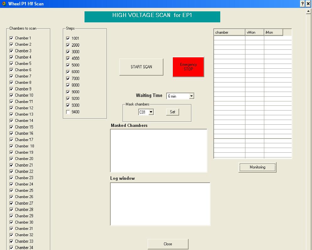
41 RPC DCS Hardware Structure Purchased by Pakistan All the RPC subsystems are handled and controlled by the RPC Supervisor, aimed to gather and summarize all the information and to present a simplified but coherent and general view to the end users. 41
42 RPC Endcap DCS Software In accordance with the CMS official guidelines, all Endcap RPC DCS applications have been developed using the commercial ETM SCADA (Supervisory Control And Data Acquisition) software, PVSS 3.6 and the standard Joint Control Project (JCOP) framework components. The DCS uses the finite state machine (FSM) approach and its follows the RPC subsystem structure (station, ring, chamber, Channel...). 42


43 Cont.. Example of the Chamber Finite State Machine. Structure of the hierarchy tree of the RPC DCS 43
44 Cont RPC DCS uses most of the functionalities provided by the PVSS + JCOP software as the final state machine, the GUI, the alarm handler and the ORACLE database interface. 44
45 Commissioning of RE DCS The NCP EHEP Group started work on DCS since Jan, The Provisional DCS version is released in August, This was a temporary setup in building 40 office by using 3 ordinary desktop computer machines(as RE Supervisor, RE LV machine and RE HV machine). This setup is capable to control and monitor the HV system, LV system of three Endcap Discs. i.e. 432 HV channels and 216 LV Channels. 45


46 Commissioning of RE DCS One User interface panel for example. 46
47 Provisional DCS Provisional DCS provides functionalities such as: Easy user interface with hardware in form of tree view. Power On or Off the Disc/Ring/Single RPC via UI panel. Settings for Current and Voltage parameters for both HV and LV systems like voltage, current, trip time etc. Generate plots for HV Vs Current for each HV and LV channel of RPC separately. Maintains History for Current and Voltage to analyze in detail the behavior of the hardware. Generate Alarms in case of unusual situations like high current or high temperature of boards. Turn off the respective board/channel in case of bad situation to avoid the failure of hardware, etc.. 47

48 Global Settings for ring 48
49 Provisional DCS From August 2008 till February 2009, the provisional DCS is used by CMS shifters on 24 hours basis. The provisional DCS helped a lot to shifters to monitor and analyze in detail the behavior of RPC Endcap HV and LV system. In the mean time several updates were implemented to improve the user interface and to make it more robust and secure. Extensive work has been done on supervisor system to integrate the Barrel and Endcap in one project which is very complicated and requires continuous work and discussions of Barrel DCS expert with Endcap DCS expert. 49

50 Final RPC DCS In February 2009, the final RPC DCS version is released which has common supervisor for RPC Endcap and Barrel. All RPC Endcap DCS computer machines are installed in CMS central DCS control room and are on CMS internal network. The RPC DCS has been also successfully integrated into the Central DCS and was able to publish its state and receive commands from it. 50

51 Cont.. Final DCS adds more functionalities in provisional DCS such as: Provide control and monitoring of HV, LV, LBB temperature and humidity channels and sensors on disc level. Global monitoring of RPC Endcap six stations Average and total temperature per disc. Average and total current per disc. Provide HV Scan utility. 51
52 Cont.. Integration of Gas system in RPC Endcap DCS. More user friendly. Addition of monitoring of online temperature of hardware like boards, power supplies etc. Addition of emergency shutdown capability of HV and LV of all stations. After a short debug phase, the system ran without problems for the entire test period. It was proved to be able to manage properly the interruptions occurred, due to power failures and communication problem with the power supply. 52
53 Cont.. Final DCS is more robust and secure than provisional DCS and have more detailed information of the hardware. The DCS proved to be a reliable tool for the safe and correct operation of the detectors and trained shifter, were able to operate the detector in a easy and safe way. Some DCS UI panels are shown in next slides. 53


54 RPC Endcap DCS Overview 54
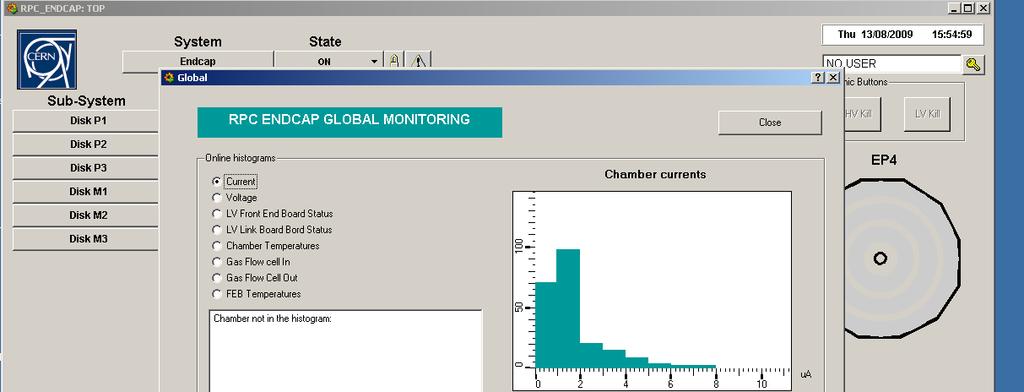
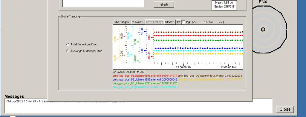
55 Global Monitoring 55
56 56

57 Cont.. HV Channels for disk 57

58 Cont.. LBB Channels for disk 58


59 HV Setting for Disk LV Setting for Disk 59

60 Cont.. Global Monitoring for disk 60

61 Boards and AC to DC Convertor Temperature 61

62 Temperature and Humidity for disk 62


63 Current plots at 9.2kV for selected RPCs 63
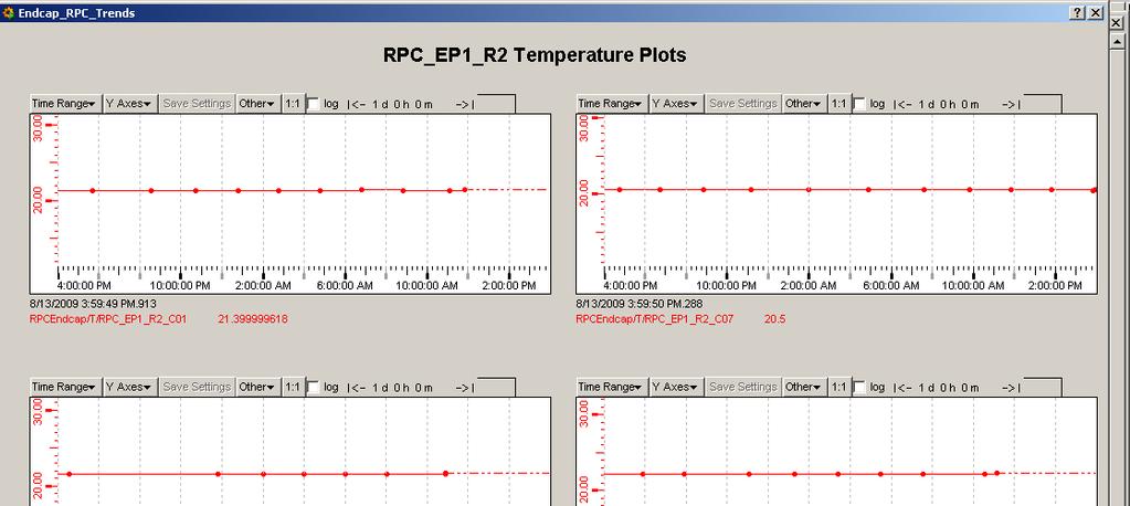
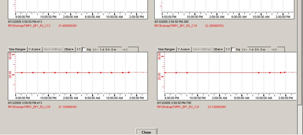
64 Temperature plots for one station 64

65 Water temperature sensors plots for one station 65
66 Conclusion The design and development of the Endcap RPC detector control system is now finished and shifters are using it on 24 hours basis. The good results obtained during the 2008 and 2009 global runs and in August 2009 CRAFT operating whole RPC Endcap system, demonstrated that the RPC DCS was well designed and was able to run in a very stable and safe way for long period. In conclusion, the RPC DCS system, developed following the guidelines of the DCS central group was proved to be a reliable tool and it is ready to become fully operational for the Winter 2009 and whole 2010 when CMS will begin to take data. 66

67 67
Detector Control System for Endcap Resistive Plate Chambers
 Detector Control System for Endcap Resistive Plate Chambers Taimoor Khurshid National Center for Physics, Islamabad, Pakistan International Scientific Spring March 01, 2010 Contents CMS Endcap RPC Hardware
Detector Control LHC
 Detector Control Systems @ LHC Matthias Richter Department of Physics, University of Oslo IRTG Lecture week Autumn 2012 Oct 18 2012 M. Richter (UiO) DCS @ LHC Oct 09 2012 1 / 39 Detectors in High Energy
Front-End Electronics Configuration System for CMS. Philippe Gras CERN - University of Karlsruhe
 Front-End Electronics Configuration System for CMS Philippe Gras CERN - University of Karlsruhe Outline Introduction Tracker electronics parameters Tracker beam test DCS overview Electronics configuration
ATLAS DCS Overview SCADA Front-End I/O Applications
 Overview SCADA Front-End I/O Applications ATLAS TDAQ week, July 6th 2001, H.J.Burckhart 1 SCX1 USA15 Common Infrastructure PC Local Area Network Server Operation Local Control Stations (LCS) Expert Subdetector
Control slice prototypes for the ALICE TPC detector
 Control slice prototypes for the ALICE TPC detector S.Popescu 1, 3, A.Augustinus 1, L.Jirdén 1, U.Frankenfeld 2, H.Sann 2 1 CERN, Geneva, Switzerland, 2 GSI, Darmstadt, Germany, 3 NIPN E, Bucharest, Romania
AN OVERVIEW OF THE LHC EXPERIMENTS' CONTROL SYSTEMS
 AN OVERVIEW OF THE LHC EXPERIMENTS' CONTROL SYSTEMS C. Gaspar, CERN, Geneva, Switzerland Abstract The four LHC experiments (ALICE, ATLAS, CMS and LHCb), either by need or by choice have defined different
Motivation Requirements Design Examples Experiences Conclusion
 H1DCM Network based Detector Control and Monitoring for the H1 Experiment Seminar on Computing in High Energy Physics G. Eckerlin (H1 Collaboration) Motivation Requirements Design Examples Experiences
Experiment
 Experiment Control@LHC An Overview Many thanks to the colleagues in the four experiments and the EN/ICE group, in particular: ALICE: Franco Carena, Vasco Chibante Barroso (DAQ), Andre Augustinus (DCS)
First experiences with the ATLAS pixel detector control system at the combined test beam 2004
 Nuclear Instruments and Methods in Physics Research A 565 (2006) 97 101 www.elsevier.com/locate/nima First experiences with the ATLAS pixel detector control system at the combined test beam 2004 Martin
Oliver Holme Diogo Di Calafiori Günther Dissertori. For the CMS collaboration
 Maintaining an effective and efficient control system for the Electromagnetic Calorimeter of the Compact Muon Solenoid experiment during long-term operations of CERN s Large Hadron Collider Oliver Holme
2008 JINST 3 S Online System. Chapter System decomposition and architecture. 8.2 Data Acquisition System
 Chapter 8 Online System The task of the Online system is to ensure the transfer of data from the front-end electronics to permanent storage under known and controlled conditions. This includes not only
2008 JINST 3 S Control System. Chapter Detector Control System (DCS) Introduction Design strategy and system architecture
 Introduction Design strategy and system architecture") Chapter 7 Control System 7.1 Detector Control System (DCS) 7.1.1 Introduction The primary task of the ALICE Control System is to ensure safe and correct operation of the ALICE experiment [17]. It provides
Chapter 7 Control System 7.1 Detector Control System (DCS) 7.1.1 Introduction The primary task of the ALICE Control System is to ensure safe and correct operation of the ALICE experiment [17]. It provides
ALICE TOF Shifters Instructions. ALICE TOF Team 09/11/2009
 ALICE TOF Shifters Instructions ALICE TOF Team 09/11/2009 Table of Contents Table of Contents... 2 1. Foreword... 3 2. Shifters tasks... 3 3. Starting... 4 4. TOF DCS User Interface... 4 4.1 Description
The Compact Muon Solenoid Experiment. Conference Report. Mailing address: CMS CERN, CH-1211 GENEVA 23, Switzerland
 Available on CMS information server CMS CR -2015/215 The Compact Muon Solenoid Experiment Conference Report Mailing address: CMS CERN, CH-1211 GENEVA 23, Switzerland 05 October 2015 (v2, 08 October 2015)
VERY HIGH VOLTAGE CONTROL FOR ALICE TPC
 VERY HIGH VOLTAGE CONTROL FOR ALICE TPC André Augustinus 1, Joachim Baechler 1, Marco Boccioli 1, Uli Frankenfeld 2, Lennart Jirdén 1 1 CERN, Geneva, Switzerland; 2 GSI, Darmstadt, Germany ABSTRACT The
T HE discovery at CERN of a new particle
 1 ALFA Detector Control System Luis Seabra, LIP - Laboratório de Instrumentação e Física Experimental de Partículas, Lisbon, Portugal, on behalf of the ALFA group Abstract ALFA (Absolute Luminosity For
The CERN Detector Safety System for the LHC Experiments
 The CERN Detector Safety System for the LHC Experiments S. Lüders CERN EP/SFT, 1211 Geneva 23, Switzerland; Stefan.Lueders@cern.ch R.B. Flockhart, G. Morpurgo, S.M. Schmeling CERN IT/CO, 1211 Geneva 23,
Overview of DCS Technologies. Renaud Barillère - CERN IT-CO
 Overview of DCS Technologies Renaud Barillère - CERN IT-CO DCS components Extensions SCADA Supervision OPC or DIM Ethernet PLC FE (UNICOS) Fieldbus Custom FE Process management Fieldbus protocols Field
Stefan Koestner on behalf of the LHCb Online Group ( IEEE - Nuclear Science Symposium San Diego, Oct.
 Stefan Koestner on behalf of the LHCb Online Group (email: Stefan.Koestner@cern.ch) IEEE - Nuclear Science Symposium San Diego, Oct. 31 st 2006 Dedicated to B-physics : single arm forward spectrometer
JCOP Workshop III. Status of JCOP Activities. 5 th & 6 th June Wayne Salter, CERN IT-CO
 JCOP Workshop III 5 th & 6 th June 2002 Status of JCOP Activities Wayne Salter, CERN IT-CO What was the situation at the last Workshop? Detailed review of SCADA technology SCADA evaluation just finished
Design specifications and test of the HMPID s control system in the ALICE experiment.
 Design specifications and test of the HMPID s control system in the ALICE experiment. E. Carrone For the ALICE collaboration CERN, CH 1211 Geneva 23, Switzerland, Enzo.Carrone@cern.ch Abstract The HMPID
Design for High Voltage Control and Monitoring System for CMS Endcap Electromagnetic Calorimeter
 Industrial Placement Project Report Design for High Voltage Control and Monitoring System for CMS Endcap Electromagnetic Calorimeter Author: Funai Xing Supervisors: Dr. Helen Heath (Bristol) Dr. Claire
Control and Monitoring of the Front-End Electronics in ALICE
 Control and Monitoring of the Front-End Electronics in ALICE Peter Chochula, Lennart Jirdén, André Augustinus CERN, 1211 Geneva 23, Switzerland Peter.Chochula@cern.ch Abstract This paper describes the
SOFTWARE SCENARIO FOR CONTROL SYSTEM OF INDUS-2
 10th ICALEPCS Int. Conf. on Accelerator & Large Expt. Physics Control Systems. Geneva, 10-14 Oct 2005, WE3B.3-70 (2005) SOFTWARE SCENARIO FOR CONTROL SYSTEM OF INDUS-2 ABSTRACT R. K. Agrawal *, Amit Chauhan,
The detector control system of the ATLAS experiment
 Journal of Instrumentation OPEN ACCESS The detector control system of the ATLAS experiment To cite this article: A Barriuso Poy et al View the article online for updates and enhancements. Related content
Detector controls meets JEE on the web
 Detector controls meets JEE on the web ICALEPCS 2015 Frank Glege Outline Part 1: Web based Remote access to controls systems Part 2: JEE for controls 20.10.2015 Frank Glege 2 About CERN 20.10.2015 Frank
CMS ECAL Endcap High Voltage PVSS System Expert Manual
 CMS ECAL Endcap High Voltage PVSS System Expert Manual v3.0 last updated: 26/08/2005 Maintained by: CMS Group CCLRC Rutherford Appleton Laboratory Contents 1. Brief Introduction 3 2. Expert Configurations
Implementation of a Control System for the μmegas Detector National Technical University of Athens Stefanos G. Leontsinis 1 1 School of Applied Mathem
 Implementation of a Control System for the μmegas Detector National Technical University of Athens Stefanos G. Leontsinis 1 1 School of Applied Mathematical and Physical Sciences November 2nd, 2009 Outline
First Operational Experience from the LHCb Silicon Tracker
 First Operational Experience from the LHCb Silicon Tracker 7 th International Hiroshima Symposium on Development and Application of Semiconductor Tracking Devices The LHCb Silicon Tracker Installation
NA60 Detector Control System
 NA60 note 2002-8 Nov. 29, 2002 NA60 Detector Control System Nicolas Guettet CERN-EP/NA60 Abstract: This note is a report on the Detector Control System of the NA60 experiment. We describe its global architecture,
Ignacy Kudla, Radomir Kupczak, Krzysztof Pozniak, Antonio Ranieri
 *** Draft *** 15/04/97 *** MK/RK/KTP/AR *** ***use color print!!!*** RPC Muon Trigger Detector Control Ignacy Kudla, Radomir Kupczak, Krzysztof Pozniak, Antonio Ranieri $Ã&06 Ã*(1(5$/ RPC Muon Trigger
Low Voltage Control for the Liquid Argon Hadronic End-Cap Calorimeter of ATLAS
 Low Voltage Control for the Liquid Argon Hadronic End-Cap Calorimeter of ATLAS H.Brettel *, W.D.Cwienk, J.Fent, H.Oberlack, P.Schacht Max-Planck-Institut für Physik, Werner-Heisenberg-Institut, Foehringer
Common Software for Controlling and Monitoring the Upgraded CMS Level-1 Trigger
 Common Software for Controlling and Monitoring the Upgraded CMS Level-1 Trigger Giuseppe Codispoti, Simone Bologna, Glenn Dirkx, Christos Lazaridis, Alessandro Thea, Tom Williams TIPP2017: International
The LHC Compact Muon Solenoid experiment Detector Control System
 Journal of Physics: Conference Series The LHC Compact Muon Solenoid experiment Detector Control System To cite this article: G Bauer et al 2011 J. Phys.: Conf. Ser. 331 022009 View the article online for
COMPASS Framework documentation
 COMPASS Framework documentation COMPASS Framework DCS team 1 CERN-IT-CO, COMPASS v1.4, 24-November-2000 1 Purpose This document describes the framework which was designed for the COMPASS experiment. This
SMI++ object oriented framework used for automation and error recovery in the LHC experiments
 Journal of Physics: Conference Series SMI++ object oriented framework used for automation and error recovery in the LHC experiments To cite this article: B Franek and C Gaspar 2010 J. Phys.: Conf. Ser.
IN a system of many electronics boards of many different
 356 IEEE TRANSACTIONS ON NUCLEAR SCIENCE, VOL. 55, NO. 1, FEBRUARY 2008 Building Integrated Remote Control Systems for Electronics Boards Richard Jacobsson, Member, IEEE Abstract This paper addresses several
The Compact Muon Solenoid Experiment. Conference Report. Mailing address: CMS CERN, CH-1211 GENEVA 23, Switzerland
 Available on CMS information server CMS CR -2017/188 The Compact Muon Solenoid Experiment Conference Report Mailing address: CMS CERN, CH-1211 GENEVA 23, Switzerland 29 June 2017 (v2, 07 July 2017) Common
JCOP FW Training Course. 30 June 4 July 2014 EN-ICE
 JCOP FW Training Course 30 June 4 July 2014 EN-ICE Location and Time Schedule Location Building:Training Center 593-572 Room #25 Schedule Monday: 14:00-17:30 Tuesday Friday: 09:00-12:30 14:00-17:30 Front-End
Muon Reconstruction and Identification in CMS
 Muon Reconstruction and Identification in CMS Marcin Konecki Institute of Experimental Physics, University of Warsaw, Poland E-mail: marcin.konecki@gmail.com An event reconstruction at LHC is a challenging
A Fast VME Data Acquisition System for Spill Analysis and Beam Loss Measurement
 A Fast VME Data Acquisition System for Spill Analysis and Beam Loss Measurement T. Hoffmann, D. A. Liakin *, P. Forck Gesellschaft für Schwerionenforschung (GSI), Planckstraße 1, D-64291Darmstadt * ITEP
DDC Experience at Tilecal
 Workshop, Nikhef,Oct 2001 Fernando Varela R. DDC Experience at Tilecal Outline Tilecal testbeam setup DDC Work Findings Improvement suggestions Conclusions This talk report on the first usage of the DDC
DCS Caen Device Units
 DCS Caen Device Units DCS Caen Device Units... 1 1 DCS CAEN Device Units... 3 1.1 Device Units Created... 4 1.2 State Diagrams... 4 2 Installation and Operation... 7 2.1 Panels Created... 8 2.2 Customization
Communication Software for the ALICE TPC Front-End Electronics
 Communication Software for the ALICE Front-End Electronics M. Richter 1, J. Alme 1, T. Alt 4, S. Bablok 1, U. Frankenfeld 5, D. Gottschalk 4, R. Keidel 3, Ch. Kofler 3, D. T. Larsen 1, V. Lindenstruth
The CMS data quality monitoring software: experience and future prospects
 The CMS data quality monitoring software: experience and future prospects Federico De Guio on behalf of the CMS Collaboration CERN, Geneva, Switzerland E-mail: federico.de.guio@cern.ch Abstract. The Data
Accelerator Control System
 Chapter 13 Accelerator Control System 13.1 System Requirements The KEKB accelerator complex has more than 50,000 control points along the 3 km circumference of the two rings, the LER and HER. Some control
Power Supply. products. CAEN Short Form Catalog Function Model Description Page. NIM Power Supply N470 4 Channel Programmable HV Power Supply 15
 Power Supply products CAEN Short Form Catalog 2007 Function Model Description Page NIM Power Supply N470 4 Channel Programmable HV Power Supply 15 NIM Power Supply N471 2 Channel HV Power Supply (± 8 kv)
Data Quality Monitoring Display for ATLAS experiment
 Data Quality Monitoring Display for ATLAS experiment Y Ilchenko 1, C Cuenca Almenar 2, A Corso-Radu 2, H Hadavand 1, S Kolos 2, K Slagle 2, A Taffard 2 1 Southern Methodist University, Dept. of Physics,
Control and Spy the TELL1. Cédric Potterat EPFL LPHE
 Control and Spy the TELL1 Cédric Potterat EPFL LPHE 1 outlines ECS control PVSS for TELL1 DIM, fwccpc, fwhw Status Recipes outlook 2 PVSS CERN Used for the slow control systems by all LHC experiments Open
Modules and Front-End Electronics Developments for the ATLAS ITk Strips Upgrade
 Modules and Front-End Electronics Developments for the ATLAS ITk Strips Upgrade Carlos García Argos, on behalf of the ATLAS ITk Collaboration University of Freiburg International Conference on Technology
The High Performance Archiver for the LHC Experiments
 The High Performance Archiver for the LHC Experiments Manuel Gonzalez Berges CERN, Geneva (Switzerland) CERN - IT Department CH-1211 Genève 23 Switzerland www.cern.ch/it Outline Context Archiving in PVSS
JCOP EXPERIENCE WITH A COMMERCIAL SCADA PRODUCT, PVSS
 JCOP EXPERIENCE WITH A COMMERCIAL SCADA PRODUCT, PVSS P. C. Burkimsher, CERN, Geneva, Switzerland Abstract In 1999, the four CERN Large Hadron Collider (LHC) experiments together chose a commercial Supervisory
The Detector Control System for the HMPID in the ALICE Experiment at LHC.
 The Detector Control System for the HMPID in the LICE Eperiment at LHC. De Cataldo, G. for the LICE collaboration INFN sez. Bari, Via G. mendola 173, 70126 Bari, Italy giacinto.decataldo@ba.infn.it bstract
Vertex Detector Electronics: ODE to ECS Interface
 Vertex Detector Electronics: ODE to ECS Interface LHCb Technical Note Issue: 1 Revision: 0 Reference: LHCb 2000-012 VELO Created: 1 February 2000 Last modified: 20 March 2000 Prepared By: Yuri Ermoline
0.1 Slow Monitoring and Recording System
 0.1 Slow Monitoring and Recording System A slow monitoring and control system is required to control systematic effects that could impact the experiment, to allow automated scans of parameters such as
AUTOMATION OF POWER DISTRIBUTION USING SCADA
 1 2 ABSTRACT In every substation certain measurements, supervision, control, operation and protection functions are necessary. Traditionally these functions were performed manually by system operator from
MiniDAQ1 A COMPACT DATA ACQUISITION SYSTEM FOR GBT READOUT OVER 10G ETHERNET 22/05/2017 TIPP PAOLO DURANTE - MINIDAQ1 1
 MiniDAQ1 A COMPACT DATA ACQUISITION SYSTEM FOR GBT READOUT OVER 10G ETHERNET 22/05/2017 TIPP 2017 - PAOLO DURANTE - MINIDAQ1 1 Overview LHCb upgrade Optical frontend readout Slow control implementation
A Web-based control and monitoring system for DAQ applications
 A Web-based control and monitoring system for DAQ applications Alexey Anisenkov (BINP) Ivan Logashenko (BINP) Daniil Zhadan (BINP) CHEP 2018, Bulgaria, 9 July 2018 Outline The Role of monitoring in Online
BCPro System Product Bulletin
 CH-BCM100-0, CH-BCM200-0 Introduction The BCPro system from Johnson Controls is ideally suited to automating the environmental control and energy usage functions of conventional buildings. Not only does
Deployment of NI COTS Hardware and LabVIEW in the C2 FRC Experiment
 Deployment of NI COTS Hardware and LabVIEW in the C2 FRC Experiment A Sibley1, C White2, S Primavera1 and the TAE Control Team 1 2 Tri Alpha Energy, PO Box 7010, Rancho Santa Margarita CA 92688-7010 ThinkG
Using Operator Interfaces to Optimize Performance of Industrial Wireless Networks
 Using Operator Interfaces to Optimize Performance of Industrial Wireless Networks Jim Ralston, Wireless Sales Engineer ProSoft Technology, August 2007 Abstract The performance of wireless networks can
ELECTRICAL NETWORK SUPERVISOR STATUS REPORT
 EUROPEAN ORGANIZATION FOR NUCLEAR RESEARCH ORGANISATION EUROPÉENNE POUR LA RECHERCHE NUCLÉAIRE CERN - ST Division CERN-ST-2001-018 30 January 2001 ELECTRICAL NETWORK SUPERVISOR STATUS REPORT S. Poulsen
Real-time Power System Operation. Energy Management Systems. Introduction
 1 Real-time Power System Operation Energy Management Systems Introduction The time frame for Power Systems Operation varies from a few seconds to a week. To assist with the operation of the system, modern
Verification and Diagnostics Framework in ATLAS Trigger/DAQ
 Verification and Diagnostics Framework in ATLAS Trigger/DAQ M.Barczyk, D.Burckhart-Chromek, M.Caprini 1, J.Da Silva Conceicao, M.Dobson, J.Flammer, R.Jones, A.Kazarov 2,3, S.Kolos 2, D.Liko, L.Lucio, L.Mapelli,
Software for implementing trigger algorithms on the upgraded CMS Global Trigger System
 Software for implementing trigger algorithms on the upgraded CMS Global Trigger System Takashi Matsushita and Bernhard Arnold Institute of High Energy Physics, Austrian Academy of Sciences, Nikolsdorfer
Accord Builder. User Guide
 User Guide Document: V 3.6 User Guide R01 V3.6 User Guide R01 Page 1 of 110 Table of Contents 1 Introduction... 7 2 General Summary and Definitions... 8 2.1 Accord Platform and Plant... 8 2.2 PLC Control
Quad Module Hybrid Development for the ATLAS Pixel Layer Upgrade
 Quad Module Hybrid Development for the ATLAS Pixel Layer Upgrade Lawrence Berkeley National Lab E-mail: kedunne@lbl.gov Maurice Garcia-Sciveres, Timon Heim Lawrence Berkeley National Lab, Berkeley, USA
RT12-240V/2.4kW Rectifier Specification
 The RT12-240V/2.4kW is a switched mode rectifier (SMR) module that delivers up to 2.4kW of output power (and up to 11A output current) into a 240V nominal DC system. The RT12 suits AC supply voltages between
Multilink. Ethernet Communications for Industrial Automation, Power Utility, and Traffic Control markets. Multilin
 Multilink Ethernet Communication switches Ethernet for Industrial Automation, Power Utility, and Traffic Control markets Key Benefits The MultiLink family is a line of Industrial and Substation Hardened
WW HMI SCADA Connectivity and Integration - Multi-Galaxy
 Slide 1 WW HMI SCADA-06 2014 Connectivity and Integration - Multi-Galaxy Steven L. Weygandt Portfolio Product Manager - Device Integration /Wonderware Social.Invensys.com @InvensysOpsMgmt / #SoftwareRevolution
An ATCA framework for the upgraded ATLAS read out electronics at the LHC
 An ATCA framework for the upgraded ATLAS read out electronics at the LHC Robert Reed School of Physics, University of the Witwatersrand, Johannesburg, South Africa E-mail: robert.reed@cern.ch Abstract.
FAST site EMU CSC test results a global view from ROOT N. Terentiev
 FAST site EMU CSC test results a global view from ROOT US N. Terentiev (Carnegie Mellon University) Fermilab July 23, 2004 CMS Endcap Muon Cathode Strip Chambers (EMU CSC) EMU CSC provides: BX identification
RT4F-110V/25A RECTIFIER
 The RT4F-110V/25A is a hot-pluggable switched mode rectifier (SMR) module designed to provide up to 25A of output current into a 110V nominal system. Examples of such systems are 60 cells lead acid (136V
RT4B-110V/12A RECTIFIER
 The RT4B-110V/12A is a switched mode rectifier (SMR) module designed to provide up to 12A of output current into a 110V nominal system. It can be used with or without a cooling fan. With a fan it runs
A New Segment Building Algorithm for the Cathode Strip Chambers in the CMS Experiment
 EPJ Web of Conferences 108, 02023 (2016) DOI: 10.1051/ epjconf/ 201610802023 C Owned by the authors, published by EDP Sciences, 2016 A New Segment Building Algorithm for the Cathode Strip Chambers in the
CONTROL AND MONITORING OF ON-LINE TRIGGER ALGORITHMS USING GAUCHO
 10th ICALEPCS Int. Conf. on Accelerator & Large Expt. Physics Control Systems. Geneva, 10-14 Oct 2005, WE3A.5-6O (2005) CONTROL AND MONITORING OF ON-LINE TRIGGER ALGORITHMS USING GAUCHO E. van Herwijnen
Australian Nuclear Science & Technology Organisation. Upgrade of the ANTARES Computer Control System and our experience of EPICS.
 Australian Nuclear Science & Technology Organisation Upgrade of the ANTARES Computer Control System and our experience of EPICS. Damien Lynch Why Upgrade? Remove reliance on old difficult to replace hardware
HARDWARE OF SUPERVISORY CONTROL & DATA ACQUISITION SYSTEM
 Chapter 3 HARDWARE OF SUPERVISORY CONTROL & DATA ACQUISITION SYSTEM Dr. H.K. VERMA Distinguished Professor Department of Electrical and Electronics Engineering School of Engineering and Technology SHARDA
UNICOS* Principles and History
 Industrial Controls & Unicos UNICOS* Principles and History LHC-CP workshop 3 Session 3 *UNified Industrial COntrol System & not UNified Industrial COntrol System for Cryogenics could become UNICEF for
TO KEEP development time of the control systems for LHC
 362 IEEE TRANSACTIONS ON NUCLEAR SCIENCE, VOL. 55, NO. 1, FEBRUARY 2008 Generic and Layered Framework Components for the Control of a Large Scale Data Acquisition System Stefan Koestner, Member, IEEE,
The ATLAS Conditions Database Model for the Muon Spectrometer
 The ATLAS Conditions Database Model for the Muon Spectrometer Monica Verducci 1 INFN Sezione di Roma P.le Aldo Moro 5,00185 Rome, Italy E-mail: monica.verducci@cern.ch on behalf of the ATLAS Muon Collaboration
THE ATLAS experiment comprises a significant number
 386 IEEE TRANSACTIONS ON NUCLEAR SCIENCE, VOL. 55, NO. 1, FEBRUARY 2008 Access Control Design and Implementations in the ATLAS Experiment Marius Constantin Leahu, Member, IEEE, Marc Dobson, and Giuseppe
UNICOS PVSS (WinCC OA) Project Maintenance
 Project Maintenance") CERN CH1211 Geneva 23 Switzerland EDMS NO. REV. VALIDITY 0000000 1.0 DRAFT REFERENCE XXXX Date : 2011-07-04 EN-ICE Workshop 2012 UNICOS PVSS (WinCC OA) Project Maintenance Proposal of guidelines DOCUMENT
CERN CH1211 Geneva 23 Switzerland EDMS NO. REV. VALIDITY 0000000 1.0 DRAFT REFERENCE XXXX Date : 2011-07-04 EN-ICE Workshop 2012 UNICOS PVSS (WinCC OA) Project Maintenance Proposal of guidelines DOCUMENT
Control Systems: an Application to a High Energy Physics Experiment (COMPASS)
") Control Systems: an Application to a High Energy Physics Experiment (COMPASS) P. Bordalo, A.S. Nunes, C. Pires, C. Quintans and S. Ramos LIP, 1000-149 Lisbon, Portugal IST, Universidade Técnica de Lisboa,
Control Systems: an Application to a High Energy Physics Experiment (COMPASS) P. Bordalo, A.S. Nunes, C. Pires, C. Quintans and S. Ramos LIP, 1000-149 Lisbon, Portugal IST, Universidade Técnica de Lisboa,
Detector Control System board for FAIR. J. A. Lucio Martínez Infrastructure and Computer Systems in Data Processing (IRI) Goethe University Frankfurt
 Goethe University Frankfurt") Detector Control System board for FAIR J. A. Lucio Martínez Infrastructure and Computer Systems in Data Processing (IRI) Goethe University Frankfurt For the PANDA Collaboration Meeting in Darmstadt, 08.06.2016
Detector Control System board for FAIR J. A. Lucio Martínez Infrastructure and Computer Systems in Data Processing (IRI) Goethe University Frankfurt For the PANDA Collaboration Meeting in Darmstadt, 08.06.2016
RT4F-120V/20A-WAC RECTIFIER
 The RT4F-120V/20A-WAC is a switched mode rectifier/charger module designed to provide up to 20A of output current into a 120V nominal system. This charger has been designed for use in conjunction with
SCADA Software. 3.1 SCADA communication architectures SCADA system
 3 SCADA Software 3.1 SCADA communication architectures 3.1.1 SCADA system A supervisory control and data acquisition (SCADA) system means a system consisting of a number of remote terminal units (RTUs)
The CMS L1 Global Trigger Offline Software
 The CMS L1 Global Offline Software Vasile Mihai Ghete Institute for High Energy Physics, Vienna, Austria Seminar 08-09 June 2009, HEPHY Vienna CMS experiment Tracker pixel detector: 3 barrel layers, 2
1. INTRODUCTION 2. MUON RECONSTRUCTION IN ATLAS. A. Formica DAPNIA/SEDI, CEA/Saclay, Gif-sur-Yvette CEDEX, France
 &+(3/D-ROOD&DOLIRUQLD0DUFK 1 Design, implementation and deployment of the Saclay muon reconstruction algorithms (Muonbox/y) in the Athena software framework of the ATLAS experiment A. Formica DAPNIA/SEDI,
I/A Series HARDWARE Product Specifications
 I/A Series HARDWARE Product Specifications I/A Series Station Computing Device (SCD) SCD5200 CPU OptoNet Power Supply Ethernet (COPE) Module/ SCD5200 CPU OptoNet Ethernet (COE) Module PSS 21H-8G3 B4 FEATURES
THE ALICE experiment described in [1] will investigate
![THE ALICE experiment described in [1] will investigate](/thumbs/88/115374718.jpg "THE ALICE experiment described in [1] will investigate") 980 IEEE TRANSACTIONS ON NUCLEAR SCIENCE, VOL. 53, NO. 3, JUNE 2006 The Control System for the Front-End Electronics of the ALICE Time Projection Chamber M. Richter, J. Alme, T. Alt, S. Bablok, R. Campagnolo,
980 IEEE TRANSACTIONS ON NUCLEAR SCIENCE, VOL. 53, NO. 3, JUNE 2006 The Control System for the Front-End Electronics of the ALICE Time Projection Chamber M. Richter, J. Alme, T. Alt, S. Bablok, R. Campagnolo,
2003 TEC beam test : a quick overview
 2003 TEC beam test : a quick overview Presentation: A petal in the beam line! Power supplies, cooling, interlock... The available measurements. Some plots taken from the online monitoring. Post X5 studies.
Intelligence Elements and Performance of the FPGA-based DAQ of the COMPASS Experiment
 Intelligence Elements and Performance of the FPGA-based DAQ of the COMPASS Experiment Stefan Huber, Igor Konorov, Dmytro Levit, Technische Universitaet Muenchen (DE) E-mail: dominik.steffen@cern.ch Martin
Veesta World Co. V-SCADA2000 Product Series. The cross platform SCADA system
 Veesta World Co. V-SCADA2000 Product Series The cross platform SCADA system 1 V-SCADA2000 Product Series 2 V-SCADA2000 Veesta SCADA Control System 2000 Product Series Overview V-SCADA2000 Series consist
The coolest place on earth
 The coolest place on earth Large Scale Messaging with ActiveMQ for Particle Accelerators at CERN 2 Overview Examples 30min Introduction to CERN Operation Usage of ActiveMQ 3 About the Speaker Member of
Experience with Data-flow, DQM and Analysis of TIF Data
 Experience with Data-flow, DQM and Analysis of TIF Data G. Bagliesi, R.J. Bainbridge, T. Boccali, A. Bocci, V. Ciulli, N. De Filippis, M. De Mattia, S. Dutta, D. Giordano, L. Mirabito, C. Noeding, F. Palla,
WinCC-OA and the JCOP Framework
 WinCC-OA and the JCOP Framework Part 4 (JCOP Framework cont.) Presented by Riku-Pekka Silvola CERN BE/ICS Recap WinCC-OA WinCC-OA Architecture & Installation Data Model with DPTs and DPs Graphics with
Incident Information Management Tool
 Incident Information Management Tool Abstract: Flaws of current incident information management at CMS and CERN are discussed. A new data model for future incident database is proposed and briefly described.
LHCb Online System BEAUTY-2002
 BEAUTY-2002 8th International Conference on B-Physics at Hadron machines June 17-21 2002 antiago de Compostela, Galicia (pain ) Niko Neufeld, CERN EP (for the LHCb Online Team) 1 Mission The LHCb Online
THE CMS apparatus [1] is a multi-purpose detector designed
![THE CMS apparatus [1] is a multi-purpose detector designed](/thumbs/81/84198647.jpg "THE CMS apparatus [1] is a multi-purpose detector designed") The CERN CMS Tracker Control System F. Drouhin, L. Gross, D. Vintache, A. Marchioro, C. Paillard, C. Ljuslin, L. Mirabito, P.G. Verdini Abstract Due to the high integration level of the experiments planned
The CERN CMS Tracker Control System F. Drouhin, L. Gross, D. Vintache, A. Marchioro, C. Paillard, C. Ljuslin, L. Mirabito, P.G. Verdini Abstract Due to the high integration level of the experiments planned