is then retained absolutely without interruption.
|
|
|
- Frank Dixon
- 5 years ago
- Views:
Transcription

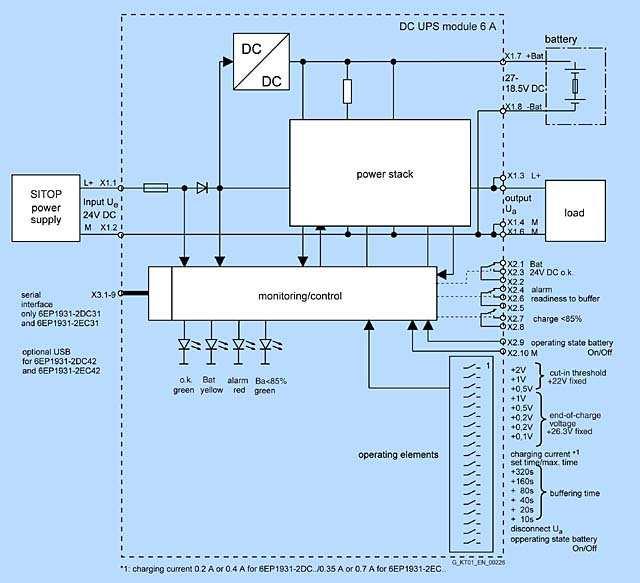
1 Page 1 of 11 DC UPS uninterruptible power supplies - DC UPS module 6 A Compact design, only 50 mm wide Simple DIN rail mounting Absolutely interruption-free buffering of mains failures through immediately electronic connection of the batteries as soon as the DC UPS input voltage drops below the value set using DIP switches High safety and availability through monitoring of operational readiness, battery supply line, battery aging (message "Battery replacement necessary") and battery charge (message "Battery charge >85%") Support of automatic restart of industrial PCs through selectable switch-off response Optionally with serial or USB interface. SW tool as download at executes under WinNT4.0, Win2000 and WinXP. The following timing diagrams show examples of the characteristic of the input and output voltages at the terminals of the DC-UPS module as well as the signal chart of the signals (relays) and of the remote signal (port). "Long" voltage failure with DC UPS without serial or USB port (Fig. 1) Voltage return only once buffer time tp (t3 follows t4) has expired: Upon failure of the input voltage on the DC-UPS module (time t1), the battery "Bat" immediately takes over the DC supply, and the output voltage U out is then retained absolutely without interruption. The isolated changeover contact "OK/Bat" switches over to its off position "Bat". At the same point in time t1, the buffer time tp set on the DIP switches is started automatically. The fact that the DIP switch is set to "Interruption output U out " in this example has no effect because the input voltage returns at time t3 only once the set buffer time (time t4) has expired. "Short" voltage failure with DC UPS without serial or USB port (Fig. 2) Voltage return before buffer time tp (t3 before t4) has expired:


2 Page 2 of 11 Upon failure of the input voltage on the DC-UPS module (time t1), the battery "Bat" immediately takes over the DC supply, and the output voltage U out is then retained absolutely without interruption. The isolated changeover contact "OK/Bat" switches over to its off position "Bat". At the same point in time t1, the buffer time tp set on the DIP switches is started automatically. With the DIP switch set to "Interruption output U out ", the output voltage U out is automatically interrupted for 5 s once the set buffer time tp (time t4) has expired. The accumulator has already been disconnected because the input voltage has returned at the time t3. If the DIP switch is not set to "Interruption output U out " there is no interruption in this example because the input voltage has already returned at time t3 prior to expiry of the set buffer time (time t4). Buffer time (time t4) automatically interrupted for 5 s and the accumulator, which has not yet been disconnected because of the missing input voltage, is simultaneously disconnected from the output. Fig. 1 "Long voltage failure" Fig. 2 "Short voltage failure" DC UPS without serial or USB port (6EP1931-2DC21/2EC21) DIP switch positions on device: buffer time tp (from 5 s to 635 s with bottom row nos. 2 to 7)//t = according to setting (with bottom row no. 1 to left)/xxxx = with setting for interruption U out (with bottom row no. 8 to left) Legend: U in : input voltage at terminals X1.1 X1.2 U out : output voltage at terminals X1.3 X1.4 and X1.5 - X1.6 OK: signal for input voltage U in OK or above the set accumulator connection threshold
3 Page 3 of 11 Bat: signal for battery operation (accumulators connected to output, accumulators power the load) Remote: signal for remote timer start with signal level = 0 at pin 7 of 9-pin serial port (pin 7 is usually the positive power supply for the port) t1: input voltage U in failed or fallen below set connection threshold t2: buffer time set on DIP switches is started by remote timer start (signal level = 0) t3: input voltage U in rises above set connection threshold t4: end of set buffer time (output is switched off and/or accumulator is disconnected) t5: output is connected again 5 s after shutdown tp: buffer time set on the DIP switches (bottom row nos. 2 to 7) "Long" voltage failure with DC UPS with serial or USB port (Fig. 3) Voltage return only once buffer time tp (t3 follows t4) has expired: Upon failure of the input voltage on the DC-UPS module (time t1), the battery "Bat" immediately takes over the DC supply, and the output voltage U out is then retained absolutely without interruption. The isolated changeover contact "OK/Bat" switches over to its off position "Bat". The buffer time tp set on the DIP switches is started at the user-selectable time t2 by means of the signal "Remote timer start" (signal level = 0 at pin 7 of the 9-pin serial port following previous signal chart according to operating instructions). The fact that the DIP switch is set to "Interruption output U out " in this example has no effect because the input voltage returns at time t3 only once the set buffer time (time t4) has expired. Note: Without a remote signal level = 0 with a setting t = max. duration, there is no interruption to the output voltage in this case because the set buffer time is not started (or interruption only if the exhaustive discharge protection disconnects the accumulator and the input voltage has not returned by then). "Short" voltage failure with DC UPS with serial or USB port (Fig. 4) Voltage return before buffer time tp (t3 before t4) has expired: Upon failure of the input voltage on the DC-UPS module (time t1), the battery "Bat" immediately takes over the DC supply, and the output voltage U out is then retained absolutely without interruption. The isolated changeover contact "OK/Bat" switches over to its off position "Bat". The buffer time tp set on the DIP switches is started at the user-selectable time t2 by means of the signal "Remote timer start" (signal level = 0 at pin 7 of the 9-pin serial port following previous signal chart according to operating instructions). With the DIP switch set to "Interruption output U out ", the output voltage U out is automatically interrupted for 5 s once the set buffer time tp (time t4) has expired. The accumulator has already been disconnected because the input voltage has returned at the time t3. The interruption to the output voltage U out for 5 s permits an automatic restart for many industrial PCs, even if the line voltage (or the input voltage U in on the DC-UPS module) returns during shutdown of the PC, as in this example. Note: Without a remote signal level = 0 with a setting t = max. duration, there is no interruption in the output voltage here because the set buffer time is not started.
 DIP switch positions on device: buffer time tp (from 5 s to 635 s with bottom row nos. 2 to 7)/t = max.")

4 Page 4 of 11 Fig. 3 "Long voltage failure" Fig. 4 "Short voltage failure" DC UPS with serial or USB port (6EP1931-2DC31/-2DC42/-2EC31/-2EC42) DIP switch positions on device: buffer time tp (from 5 s to 635 s with bottom row nos. 2 to 7)/t = max. time (with bottom row no. 1 to left)/interruption of U out (with bottom row no. 8 to left) Legend: U in :input voltage at terminals X1.1 X1.2 U out :output voltage at terminals X1.3 X1.4 and X1.5 - X1.6 OK: signal for input voltage U in OK or above the set accumulator connection threshold Bat: signal for battery operation (accumulators connected to output, accumulators power the load) Remote: signal for remote timer start with signal level = 0 at pin 7 of 9-pin serial port (pin 7 is usually the positive power supply for the port) t1: input voltage U in failed or fallen below set connection threshold t2: buffer time set on DIP switches is started by remote timer start (signal level = 0) t3: input voltage U in rises above set connection threshold t4: end of set buffer time (output is switched off and/or accumulator is disconnected) t5: output is connected again 5 s after shutdown tp: buffer time set on the DIP switches (bottom row nos. 2 to 7)

5 Page 5 of 11
6 Page 6 of 11 DC-UPS module 6 Order number 6EP DC21 6EP DC31 (with serial port) 6EP DC42 (with USB port) Input L+/M in normal operation Rated voltage U in rated 1) Voltage range Connection threshold for accumulator Rated current I in rated Controlled DC voltage 24 V DC 22 V to 29 V DC 22.5 V DC ±0.1 V (factory setting), adjustable in the range 22 V to 25.5 V DC (in 0.5-V steps) 6 A + approx. 0.6 A with empty accumulator Line buffering Line buffering or buffer time On/off control circuit Buffering time Dependent on connected accumulator and load current: With battery module 3.2 Ah (6EP1935-6MD11) at +25 C: approx. 10 min. at 6 A; 20 min. at 4 A; 45 min. at 2 A With battery module 7 Ah (6EP1935-6ME21) at +25 C: approx. 30 min. at 6 A; 45 min. at 4 A; 150 min. at 2 A External isolated NO contact required (loading max. 15 V DC/max. 10 ma). With an open control circuit, the accumulator is isolated from output L+, thus canceling line buffering. Adjustable using DIP switches to a maximum buffering time up to forced shutdown through exhaustive discharge protection (at approx. 19 V) or to a time limit of 5 to 635 s (in 10-s steps) Output L+/M in normal operation Rated voltage U out rated Voltage range Output current I out Dynamic current with overload Dynamic current with shortcircuit 24 V DC (output voltage of SITOP power supply) Input voltage U in less approx. 0.5 V DC 0 A to 6 A Electronic current limitation to 1.05 to 1.4 x I out rated for approx. 80 ms, then electronic shutdown of the output with automatic restart attempts (approx. 20-s intervals between restart attempts) Electronic current limitation to 1.5 to 3 x I out rated for
7 Page 7 of 11 approx. 20 ms, then electronic shutdown of the output with automatic restart attempts (approx. 20-s intervals between restart attempts) Output L+/M with battery operation Rated voltage U out rated Approximate voltage range Output current I out Dynamic current with overload Dynamic current with shortcircuit Output +Bat/-Bat in normal operation End-of-charge voltage U Load current I 24 V DC (from battery module) 27 V to 19 V DC at I out = 0.05 x C x 1/h or 24 V at I out = 1 x C x 1/h or 23 V at I out = 2 x C x 1/h (C = total connected accumulator capacity in Ah), 19 V disconnection threshold for exhaustive discharge protection 0 A to 6 A (constantly permissible) Electronic current limitation to 1.05 to 1.4 x I out rated for approx. 80 ms, then electronic shutdown of the output with automatic restart attempts (approx. 20-s intervals between restart attempts) Electronic current limitation to 1.5 to 3 x I out rated for approx. 20 ms, then electronic shutdown of the output with automatic restart attempts (approx. 20-s intervals between restart attempts) CVCC charging characteristic (first constant current I, then constant voltage U) 27.0 V DC ±0.1 V (factory setting), adjustable in the range 26.3 to 29.3 V (in 0.1-V steps) Approx. 0.4 A (factory setting), adjustable to 0.2 A or 0.4 A (charging is carried out with closed and open on/off circuit) Efficiency/heat loss At U out rated, I out rated approx. With battery operation approx. 95%/7 W 94.5%/8 W Protection and monitoring Reverse-polarity protection Overload protection Short-circuit protection Against polarity reversal on input voltage and accumulators Electronic current limitation to 1.05 to 1.4 x I out rated for approx. 80 ms, then electronic shutdown of the output with automatic restart attempts (approx. 20-s intervals between restart attempts) Electronic current limitation to 1.5 to 3 x I out rated for
8 Page 8 of 11 approx. 20 ms, then electronic shutdown of the output with automatic restart attempts (approx. 20-s intervals between restart attempts). Built-in, inaccessible 16 A fuse Exhaustive discharge protection Monitoring "Wire breakage in accumulator circuit" Monitoring "Accumulator replacement required" Monitoring "Accumulator charge status > 85%" Automatic shutdown if accumulator voltage below approx. 19 V Alarm signal if accumulator circuit not closed or if it opens during operation (cyclic check approximately every 20 s) Alarm signal flashing at approx Hz (approx. 2 s alarm, approx. 2 s no alarm, approx. 2 s alarm, etc.). Check every 4 hours if there has been no buffering or shutdown within 4 hours Signal to indicate that accumulators are charged to at least 85% of rated capacity Signaling 2) Normal operation Buffering or battery operation (accumulator supplies load alone or in addition to PS in the case of overload) Alarm (buffer not ready, or prewarning at and above < 20.4 V accumulator voltage) "Accumulator replacement required" "Accumulator charge status > 85%" Green LED (OK) and isolated changeover contact "24 V DC OK/Bat" at setting "24 V DC OK" 3) Yellow LED (Bat) and isolated changeover contact "24 V DC OK/Bat" at setting "Bat" (= off position) Red LED (alarm) and isolated changeover contact at setting "Alarm" (= off position). Causes of the buffer not being ready during normal operation can include: Off status or open on/off control circuit, battery module not connected, polarity reversal or defective accumulator (accumulator voltage < 18.5 V) or wire breakage between accumulator and uninterruptible-power-supply module. Signal is scanned and, thus, updated, every 20 s. Causes of the buffer not being available during buffer operation can include: Accumulator voltage has dropped below 20.4 V DC (= prewarning before shutdown through exhaustive discharge protection) and shutdown of the accumulator due to overload, short-circuit, exhaustive discharge protection or expired buffer time. The red LED then goes out. Red LED (alarm) flashing at 0.25 Hz and isolated changeover contact (alarm) switching at approx Hz Second green LED (Bat > 85%) and isolated NO contact closed (off position = open) Optional port and software Serial port Only on 6EP DC31
9 Page 9 of 11 Output of all signals and receipt of the "Remote Timerstart signal. Technical design: PC-compatible. 8N1 send and receive, 9600 baud, 8 data bits, 1 stop bit, no parity bit. Required connection to PC: 1 : 1 interconnected 9- pole sub D extension cable (connector/socket), only pin 2 (RXD), pin 3 (TDX) and pin 7 (RTS) are required. USB port Only on 6EP DC42 Output of all signals and receipt of the "Remote Timerstart signal. Technical design: Specification 2.0 with full speed, i.e., 2 Mbit/s. Supplied with +5 V by DC UPS ("selfpowered"). Required connection to PC: Commercially available 4-core shielded cable, 90 Ohm, max. 5 m, USB series "A" connector to PC and USB series "B" connector to DC UPS Software A software tool (runs under WinNT 4.0, Win 2000 and WinXP) for reading out and processing the signals is available to download from the Internet at This site also provides more information on the port. Control signals On/off control signal "Remote Timerstart" via serial port or USB Buffering is terminated or the accumulator is disconnected from the output by opening the control circuit (or by using DIP switches on the device). All other functions are retained. Starts line buffering for the set buffer time Security Primary/secondary galvanic isolation Protection class No Class III (ext. circuit and power supply unit: safety extra-low voltage required in accordance with EN 60950) EMC Emitted interference Radio interference suppression in accordance with EN 55022, limit-value curve B Noise immunity Noise immunity in accordance with EN Ambient conditions Ambient temperature during operation Transport/storage temperature 0 C to +60 C with natural convection -40 C to +70 C
10 Page 10 of 11 Degree of protection (EN 60529) IP20 Humidity class Conditions of use in accordance with EN 60721, climate class 3K3 (relative humidity 5% to 85% and Approvals absolute humidity 1 g/m 3 to 25 g/m 3 ; no condensation) CE UL/cUL CE conformity in accordance with 89/336 EEC UL 508/CSA C22.2, file E Mechanical system Input connections 24 V DC 2 screw-type terminals for 1 mm to 4 mm 2 /17 to 11 AWG Output connections 24 V DC Accumulator-module connections 24 V DC Connections for control circuit and signals Dimensions (W x H x D) in mm Required clearances 4 screw-type terminals for 1 mm to 4 mm 2 /17 to 11 AWG 2 screw-type terminals for 1 mm to 4 mm 2 /17 to 11 AWG 10 screw-type terminals for 0.5 mm to 2.5 mm 2 /20 to 13 AWG 50 x 125 x approx mm above and 50 mm below the device Weight Approx. 0.4 kg (with serial or USB port: approx kg) Mounting Snaps onto DIN rails DIN EN x15/7.5 1) All SITOP 24 V DC power supplies are permissible without restriction. 2) Permissible contact rating: 60 V DC/1 A or 30 V AC/1 A 3) "24 V DC OK" means: voltage of the power-supply unit is greater than the accumulator connection threshold set on the DC-UPS module 6.

11 Page 11 of 11
Considerations for Use. of the SITOP DC UPS Module
 Considerations for Use of the SITOP DC UPS Module 6A without interface 6A with serial interface 6A with USB interface 15A without interface 15A with serial interface 15A with USB interface 40A without
SITOP in the SIMATIC Design
 Siemens AG 2017 /2 Introduction /3 1-phase, 24 V DC (for S7-300 and ET 200M) /9 1-phase, 24 V DC (for S7-1200) /11 1-phase, 24 V DC (for S7-1500 and ET 200MP) /14 3-phase, 24 V DC (ET 200pro) Siemens KT
SIPLUS S7-200 PS 203. Overview
 SIPLUS S7-200 PS 203 Overview Design and functionality of the power supply are optimally adapted to the SIPLUS S7-200 micro PLC Slim design Particularly suitable for low cabinet depths Note: SIPLUS extreme
SITOP 3-phase 24 V DC, 20 to 40 A
 Siemens AG 2013 SITOP 3-phase, 20 to 40 A /2 SITOP 20 A /2 SITOP 20 A /2 20 A /3 SITOP PSU300B 30 A /3 SITOP 40 A /3 SITOP 40 A /3 40 A /8 Ordering data and further information For AL and ECCN export regulations
PHOENIX CONTACT - 01/2010. Features. DANGER OF EXPLOSION! Only remove equipment when it is disconnected and not in the potentially explosive area.
 Uninterruptible power supply with integrated power supply unit INTERFACE Data sheet 104211_en_00 1 Description PHOENIX CONTACT - 01/2010 Features The MINI-DC-UPS provide an uninterruptible DC voltage both
Article No. 6GK59230PS003AA2 6GK59240PS001AA2 Product Name. Power Supply SCALANCE PS924 PoE Input: 120/230V AC; Output: 54V/ 1.
 Product Name Type of power supply Electrical data Input Waveform of the input Supply Power Supply SCALANCE PS924 PoE Input: 120/230V AC; Output: 54V/ 1.6A DC; NEC Class 2 single-phase AC Power Supply SCALANCE
PHOENIX CONTACT - 01/2007
 Uninterruptible power supply INTERFACE Data Sheet 103123_00_en PHOENIX CONTACT - 01/2007 Description Especially compact and easy-to-use, the new MINI-DC-UPS/ 24 DC/2 is a combination of the power supply
CliQ II DC-UPS Module 24V 40A / DRU-24V40ABN
 Highlights & Features Full corrosion resistant Aluminium chassis Suitable for 24V system up to 40A Built-in diagnostic monitoring for DC OK, Discharge and Battery Fail by relay contacts LED indicator for
PHOENIX CONTACT - 07/2006
 Buffer module with maintenance-free capacitor-based power storage device INTERFACE Data sheet 102035_03_en PHOENIX CONTACT - 07/2006 Description Short-term mains interruptions are bridged by QUINT BUFFER,
Uninterruptible Power Supply Unit for Universal Use QUINT-DC-UPS/24DC/40
 Uninterruptible Power Supply Unit for Universal Use QUINT-DC-UPS/4DC/40. Short Description Uninterruptible Power Supply Units for Buffering Long-Term terruptions Saves space thanks to the compact, uniform
ETD-BL-1T-230(-PT) Multifunctional time relay with various functions and adjustable times. Data sheet. 1 Description
 Multifunctional time relay with various functions and adjustable times. Data sheet. 1 Description") (-PT) Multifunctional time relay with various functions and adjustable times Data sheet 106395_en_02 PHOENIX CONTACT 20-06-08 1 Description Requirements pertaining to safety and system availability increase
(-PT) Multifunctional time relay with various functions and adjustable times Data sheet 106395_en_02 PHOENIX CONTACT 20-06-08 1 Description Requirements pertaining to safety and system availability increase
Industrial Power Supplies
 50-600 Watt Features Switch mode power supplies for DIN-rail mounting 6 power ranges with 2, 3, 6, 12, 20 and 24 A output current (24 VDC models) Selectable 115/ 230 VAC input Very low ripple and noise
SITOP PSU8600 power supply system
 Siemens AG 201 /2 Introduction /5 3-phase, basic units 24 V DC (PSU8600) /10 Modular system, expansion of outputs (CNX8600) /13 Modular system, buffer (BUF8600) Siemens KT 10.1 201/2018 Siemens AG 201
QUINT-BUFFER/24DC/24DC/40
 Buffer module Data sheet 105496_en_01 PHOENIX CONTACT 2013-11-01 1 Description The QUINT BUFFER buffer module combines the electronic switchover unit and power storage in the same housing. The buffer module
Industrial Power Supplies
 75-600 Watt Features Switch mode power supplies for DIN-rail mounting 4 power ranges with 3, 6, 12 and 24 A output current (24 VDC models) Selectable 115/ 230 VAC input Very low ripple and noise EMI complies
MINI-PS AC/10-15DC/8
 Primary-Switched Power Supply, Narrow Design Data Sheet 08/2004 MINI POWER provides: An extra narrow design, with widths of 22.5 mm, 45 mm, and 67.5 mm (0.886, 1.772, and 2.657 in.) Global use due to a
Uninterruptible power supply - TRIO-UPS/1AC/24DC/
 Uninterruptible power supply with integrated power supply unit, 5A, in combination with MINI-BAT/24/DC/.3 AH, QUINT-BAT/24DC 3,4AH, 7,2AH or 2 AH Key commercial data Packing unit PCE GTIN Custom tariff
MINI-DC-UPS/12DC/4. Extract from the online catalog. Order No.:
 Extract from the online catalog MINI-DC-UPS/12DC/4 Order No.: 2866598 Uninterruptible power supply with integrated power supply unit, 4 A, in combination with MINI-BAT/12/DC 1.6 Ah or 2.6 Ah Commercial
onlinecomponents.com
 Uninterruptible Power Supply Unitfor Universal Use. Short Description Uninterruptible Power Supply Units for Buffering Long-Term terruptions Saves space thanks to the compact, uniform design Integrated
Product and functional description
 Product and functional description Connection example The universal dimmer main module N 528/31 is an installation device for DIN-rail mounting, with N-system dimensions. It is designed for lighting control,
DPM Digital DC Power Meter with Data logging capability. User Manual
 DPM-3232 Digital DC Power Meter with Data logging capability User Manual Introduction As a digital DC power meter, it measures the real time DC Voltage (5-60V), DC Current (0-60A), Watt, and it also displays
PHOENIX CONTACT Features
 Electronic monitoring relay for temperature monitoring Data sheet 107385_en_00 1 Description PHOENIX CONTACT - 2016-05-10 Features Safety and system availability requirements are constantly on the increase
Power Supply, Primary Switch Mode for Universal Use QUINT-PS AC/48DC/5
 Power Supply, Primary Switch Mode for Universal Use -PS-100-240AC/48/5 POWER provides: Preventive function monitoring through professional signaling Global use due to a wide range input A high level of
TRIO-DIODE/12-24DC/2X10/1X20
 Redundancy module INTERFACE Data sheet 104278_en_00 1 Description PHOENIX CONTACT 20100423 Features TRIO DIODE is the DINrail mountable redundancy module from the TRIO POWER product range. Using the redundancy
Operating Manual UMB ISO Converter ISOCON Order Number: 8160.UISO
 Order Number: 8160.UISO Status: V3; 17.09.2010c G. Lufft Mess- und Regeltechnik GmbH, Fellbach, Germany 1 TABLE OF CONTENTS PLEASE READ BEFORE USE... 3 DESCRIPTION... 5 UMB ISO CONVERTER ISOCON... 6 CONFIGURATION...
Chrome DC-UPS Module 24V 10A / DRU-24V10ACZ
 Highlights & Features Suitable for 24V system up to 10A Zero switch over time from loss of DC input to battery operation Built-in diagnostic monitoring for DC OK, Discharge and Battery Fail by relay contacts
QUINT-DC-UPS/24DC/10. Extract from the online catalog. Order No.:
 Extract from the online catalog QUINT-DC-UPS/24DC/10 Order No.: 2866226 Uninterruptible power supply 24 V DC/10 A, with integrated 1.3 Ah battery module. In the download area, there is a clearly arranged
QUINT-DC-UPS/24DC/40. Extract from the online catalog. Order No.:
 Extract from the online catalog QUINT-DC-UPS/24DC/40 Order No.: 2866242 Uninterruptible power supply 24 V/40 A. In the download area, there is a clearly arranged selection table available with load currents
Electronic timer CT-ERS.12 ON-delayed with 1 c/o contact Data sheet
 2CDC 251 056 F0t07 Features Rated control supply voltage 24-48 V DC, 24-240 V AC Single-function ON-delay timer One device includes 10 time ranges (0.05 s - 300 h) 1 c/o contact 2 LEDs for status indication
MINI MCR-SL-UI-REL(-SP)
") Configurable Threshold Value Switch Data Sheet 11/2004 Method of Operation The configurable 3-way threshold value switch MINI MCR-SL-UI-REL(-SP) is used to control and monitor analog standard signals.
Configurable Threshold Value Switch Data Sheet 11/2004 Method of Operation The configurable 3-way threshold value switch MINI MCR-SL-UI-REL(-SP) is used to control and monitor analog standard signals.
Electronic timer CT-ERS.21
 2CDC 251 057 F0t07 Features Rated control supply voltage 24 240 V AC/DC Single function ON delay timer One device includes 10 time ranges (0.05 s 300 h) 2 c/o contacts 2 LEDs for status indication Width
QUINT-PS/1AC/24DC/10. Extract from the online catalog. Order No.:
 Extract from the online catalog QUINT-PS/1AC/24DC/10 Order No.: 2866763 DIN rail power supply unit 24 V DC/10 A, primary-switched mode, 1- phase. The SFB technology (Selective Fusebreaking Technology)
General information Engineering with Programming package. Display with display. Supply voltage 24 V DC Yes. Input current
 Datasheet SIMATIC S7-1200, CPU 1214C, COMPACT CPU, DC/DC/DC, ONBOARD I/O: 14 DI 24V DC; 10 DO 24 V DC; 2 AI 0-10V DC, POWER SUPPLY: DC 20.4-28.8 V DC, PROGRAM/DATA MEMORY: 75 KB General information Engineering
QUINT-DC-UPS/24DC/10. Extract from the online catalog. Order No.:
 Extract from the online catalog QUINT-DC-UPS/24DC/10 Order No.: 2866226 Uninterruptible power supply 24 V DC/10 A, with integrated 1.3 Ah battery module. In the download area, there is a clearly arranged
VEO. V2UF230V10 Art.Nr.: TECHNICAL DATA
 Continous voltage monitoring Mains fluctuation detection Detects voltage drop / short interruptions of at least 10ms Prevents undefined states in switching and control systems Generates reset pulse after
MODEL CIO-EN MODBUS/TCP, MODBUS/RTU I/O MODULE
 INSTALLATION INSTRUCTIONS Revision B1 Rapid City, SD, USA, 05/2009 MODEL CIO-EN MODBUS/TCP, MODBUS/RTU I/O MODULE BE SURE POWER IS DISCONNECTED PRIOR TO INSTALLATION! FOLLOW NATIONAL, STATE AND LOCAL CODES.
PHOENIX CONTACT - 08/2009. Features. DANGER OF EXPLOSION! Only remove equipment when it is disconnected and not in the potentially explosive area.
 Primary-switched power supply for building automation INTERFACE Data sheet 103505_en_02 1 Description PHOENIX CONTACT - 08/2009 Features STEP POWER power supply units for building automation The new STEP
Power Supply HARTING pcon
 HARTING pcon 2060 Advantages Compact design and high power density Easy installation and tool-less connection Wide input range for world-wide use Wide operating temperature range (up to 70 C without derating)
Industriefunkuhren. Technical Manual. Signal Converter. for DIN Rail Mounting Series 4800xx-yy ENGLISH
 Industriefunkuhren Technical Manual Signal Converter for DIN Rail Mounting Series 4800xx-yy ENGLISH Version: 01.01-19.07.2007 2 / 23 Signal Converter 4800 - V01.01 INPORTANT NOTES Downloading Technical
DIN Rail. user manual Models , & INT /503556/ UM
 DIN Rail Power Supply user manual Models 503549, 503556 & 503563 INT-503549/503556/503563-UM-0208-01 Thank you for purchasing the INTELLINET NETWORK SOLUTIONS DIN Rail Power Supply, Model 503549 (45 W
SITOP power supply. Selectivity modules. Overview. Safety notes. Description, device design, dimension drawing. Mounting/removal 3
 Overview Safety notes 1 SITOP power supply Manual Description, device design, dimension drawing 2 Mounting/removal 3 Mounting position, mounting clearances 4 Installation 5 Technical data 6 Safety, approvals,
Control elements. Fine adjustment. Status indication. 24 V DC typ. 0,25 W / 0,25 VA. 24 V DC typ. 0,03 W / 0,09 VA. 0,15 3 s. 0,5 10 h.
 On-Delay 10 time ranges Supply voltage 24-240V AC/DC 1 change-over contact Width 22,5mm Control elements Fine adjustment Setting of time range Status indication LED U/t: Supply voltage LED R: Relay status
STEP-PS/1AC/24DC/1.75
 Primary-switched power supply, 1 AC, output current 1.75 A INTERFACE Data Sheet 103506_en_00 1 Description PHOENIX CONTACT - 05/2008 Features STEP POWER power supply units for building automation The new
Advant OCS. The Compact and Cost Effective Advant Controller. Advant Controller 210. Open Control System
 Advant OCS Open Control System Advant Controller 210 The Compact and Cost Effective Advant Controller Advant Controller 210 is a small, cost-effective system belonging to the Advant Controller family.
Solid-state Timer. Ordering Information. Ultra-slim Timer for G2R Relay Socket. H3RN-jj. Accessories (Order Separately) Connecting Socket
 Connecting Socket") Solid-state Timer Ultra-slim Timer for G2R Relay Socket Pin configuration compatible with G2R Relay and mounts to the P2R/P2RF Socket. Standard multiple time ranges and multiple operating modes. Conforms
Solid-state Timer Ultra-slim Timer for G2R Relay Socket Pin configuration compatible with G2R Relay and mounts to the P2R/P2RF Socket. Standard multiple time ranges and multiple operating modes. Conforms
General information Engineering with Programming package. Display with display. Supply voltage 24 V DC Yes. Input current
 Datasheet SIPLUS S7-1200 CPU 1214C DC/DC/DC -40... +70 DEGREES C WITH CONFORMAL COATING BASED ON 6ES7214-1AG31-0XB0. COMPACT CPU, DC/DC/DC, ONBOARD I/O: 14 DI 24V DC; 10 DO 24 V DC; 2 AI 0-10V DC, POWER
Contact protection relay
 Contact protection relay Ordering details SVR 450 08 F0000 The protects sensitive control contacts from excessive load. It can be used with latching function or without. Bounce time of control contacts
General information Engineering with Programming package. Display with display
 Datasheet SIPLUS S7-1200 CPU 1212C AC/DC/RLY -40... +70 DEGREES C WITH CONFORMAL COATING BASED ON 6ES7212-1BE31-0XB0. COMPACT CPU, AC/DC/RELAY, ONBOARD I/O: 8 DI 24V DC 6 DO RELAY 2A 2 AI 0-10V DC, POWER
Monitoring technique. VARIMETER Voltage relay MK 9064N, MH 9064
 Monitoring technique VARIMETER Voltage relay MK 9064N, MH 9064 0269462 Your Advantages Preventive maintenance For better productivity Quicker fault locating Precise and reliable Min-, Max. value or window
QUINT-PS-3x AC/24DC/10
 3-Phase Primary-Switched Power Supply Unit INTERFACE Data Sheet PHOENIX CONTACT - 12/2005 Description QUINT POWER devices are 60...960 W power supply units for universal use. This is ensured by the wide-range
General information. Display. Supply voltage. Input current. Encoder supply. Power losses
 Data sheet SIMATIC S7-1200, CPU 1215C, COMPACT CPU, DC/DC/RELAY, 2 PROFINET PORT, ONBOARD I/O: 14 DI 24V DC; 10 DO RELAY 2A, 2 AI 0-10V DC, 2 AO 0-20MA DC, POWER SUPPLY: DC 20.4-28.8 V DC, PROGRAM/DATA
Power Supply HARTING pcon
 HARTING pcon 2120 Advantages Compact design and high power density Easy installation and tool-less connection Wide input range for world-wide use Wide operating temperature range (up to 70 C without derating)
Redundancy unit CP-A RU
 2CDC 271 010 F0t06 Features Decoupling of CP power supply units with 2 inputs, each up to 20 A per input / channel Output up to 40 A True redundancy by 100 % decoupling of two parallel connected power
SITOP PSU300M/300B. SITOP power supply SITOP PSU300M/300B. Overview. Safety notes 1. Description, device design, dimension drawing 2
 Overview Safety notes 1 SITOP power supply Manual Description, device design, dimension drawing 2 Mounting/disassembly 3 Mounting position, mounting clearances 4 Installation 5 Technical data 6 Safety,
General information. Display. Supply voltage. Input current
 Datasheet SIMATIC S7-1200, CPU 1212C, COMPACT CPU, DC/DC/DC, ONBOARD I/O: 8 DI 24V DC; 6 DO 24 V DC; 2 AI 0-10V DC, POWER SUPPLY: DC 20.4-28.8 V DC, PROGRAM/DATA MEMORY: 50 KB General information Engineering
RTU500 series Data Sheet Power Supply CP-E 24/2.5
 Data Sheet Power Supply CP-E 24/2.5 Power Supply CP-E 24/2.5 Application The primary switch mode power supply offers two voltage input ranges. This enables the supply with AC or DC. Furthermore it is equipped
General information. Display. Supply voltage. Input current. Encoder supply. Output current
 Data sheet SIMATIC S7-1200, CPU 1214C, COMPACT CPU, DC/DC/RELAY, ONBOARD I/O: 14 DI 24V DC; 10 DO RELAY 2A; 2 AI 0-10V DC, POWER SUPPLY: DC 20.4-28.8 V DC, PROGRAM/DATA MEMORY: 75 KB General information
Andover Continuum. Power Supplies with or without UPS
 Andover Continuum Power Supplies with or without UPS The Andover Continuum TM PS 120/240 AC 50-U, PS 120/240 AC 65-U and PS120/240 AC 85-U power supply modules are designed to provide 24 VDC power for
Power Supply, Primary Switch Mode, Narrow Design MINI-PS AC/24DC/1
 Power Supply, Primary Switch Mode, arrow Design -PS-100-240AC/24/1 POWER provides: Extra narrow widths of 22.5, 45, and 67.5 mm (0.886, 1.772, and 2.657 in.) Global use due to a wide range input A high
What supplies 24 V DC even with voltage fluctuations, power failures, or overload reliably?
 What supplies even with voltage fluctuations, power failures, or overload reliably? SITOP power supply: the standard for reliability, compactness, and functionality Answers for industry. Always available,
Installation / Control Technique
 Installation / Control Technique Interface Relay, Interface Relay System Input-Output Interface Relay IK 3070, I_ 3070 0633 IK 3070 Circuit Diagrams IS 3070 According to IEC/EN 61 810-1 Relay, triac or
Chrome DIN Rail Power Supply 5V 7.5W 1 Phase (Class II & NEC Class 2) / DRC-5V10W1AZ
 / DRC-5V10W1AZ") Highlights & Features Protection Class II, Double Isolation (No Earth connection is required) Universal AC input voltage and full power up to 55 C Power will not de-rate for the entire input voltage range
Highlights & Features Protection Class II, Double Isolation (No Earth connection is required) Universal AC input voltage and full power up to 55 C Power will not de-rate for the entire input voltage range
General information. Display. Supply voltage. Input current. Encoder supply. Output current
 Data sheet SIMATIC S7-1200, CPU 1214C, COMPACT CPU, DC/DC/DC, ONBOARD I/O: 14 DI 24V DC; 10 DO 24 V DC; 2 AI 0-10V DC, POWER SUPPLY: DC 20.4-28.8 V DC, PROGRAM/DATA MEMORY: 75 KB General information Engineering
TSP-BCM48, TSP-BCM48A. Operating Instruction Manual. Page 1 of 13
 Battery Controller Module TSP-BCM24, TSP-BCM24A TSP-BCM48, TSP-BCM48A Operating Instruction Manual http://www.tracopower.com Page 1 of 13 Dimensions drawings: TSP-BCM24 & TSP-BCM48 Weight: 0.816lb Gewicht:
General information. Display. Supply voltage
 Data sheet SIMATIC S7-1200, CPU 1211C, COMPACT CPU, DC/DC/RELAY, ONBOARD I/O: 6 DI 24V DC; 4 DO RELAY 2A; 2 AI 0-10V DC, POWER SUPPLY: DC 20.4-28.8 V DC, PROGRAM/DATA MEMORY: 50 KB General information
TM221CE40T controller M IO transistor PNP Ethernet
 Product data sheet Characteristics TM221CE40T controller M221 40 IO transistor PNP Ethernet Complementary Main Discrete I/O number 40 Number of I/O expansion module Supply voltage limits Inrush current
Evolution 650/650 Rack 1U 850/850 Rack 1U 1150/1150 Rack 1U 1550/1550 Rack 1U Installation and user manual Pulsar Series
 www.eaton.com _ Evolution 650/650 Rack 1U 850/850 Rack 1U 1150/1150 Rack 1U 1550/1550 Rack 1U Installation and user manual Pulsar Series 34008235EN/AC - Page 2 Introduction Thank you for selecting an EATON
Electronic timer CT-AHD.22
 2CDC 251 093 F0t06 a Rotary switch for the preselection of the time range b Potentiometer with direct reading scale for the fine adjustment of the time delay c U: green LED V control supply voltage applied
Electronic timer CT-ERD.12
 2CDC 251 092 F0t06 a Rotary switch for the preselection of the time range b Potentiometer with direct reading scale for the fine adjustment of the time delay c U: green LED V control supply voltage applied
Power supply module, bus connection module
 s 8 183 8183p01, p02 TX-I/O Power supply module, bus connection module TXS1.12F10 TXS1.EF10 Each I/O row begins with one of these devices TXS1.12F10 power supply module Up to 4 power supply modules can
Electronic time relays ATI, BTI, SDT and MTI
 MAKING MODERN LIVING POSSIBLE Technical brochure Electronic time relays ATI, BTI, SDT and MTI With their robust design and many built-in functions, electronic timers ATI, BTI, SDT and MTI are ideal for
TM221M16TG controller M IO transistor PNP spring
 Characteristics controller M221 16 IO transistor PNP spring Main Range of product Product or component type [Us] rated supply voltage Discrete input number Analogue input number Discrete output type Discrete
TM221M16R controller M IO relay
 Product data sheet Characteristics TM221M16R controller M221 16 IO relay Complementary Main Discrete I/O number 16 Number of I/O expansion module Supply voltage limits Inrush current Power consumption
SITOP power supply. LOGO!Power. Overview. Safety instructions. Description, device design, dimension drawing. Mounting/removal 3
 Overview Safety instructions 1 SITOP power supply Manual Description, device design, dimension drawing 2 Mounting/removal 3 Mounting position, mounting clearances 4 Installation 5 Technical data 6 Safety,
MINI MCR-SL-UI-2I. Configurable signal duplicator. Data sheet. 1 Description
 Configurable signal duplicator Data sheet 102382_en_03 PHOENIX CONTACT 2012-05-02 1 Description The MINI MCR-SL-UI-2I(-SP)(-NC) configurable signal duplicator is used to electrically isolate, condition,
Display. Supply voltage. Input current. Encoder supply. Output current. Power losses. Memory
 Datasheet SIMATIC S7-1200, CPU 1214C, COMPACT CPU, AC/DC/RLY, ONBOARD I/O: 14 DI 24V DC; 10 DO RELAY 2A; 2 AI 0-10V DC, POWER SUPPLY: AC 85-264 V AC AT 47-63 HZ, PROGRAM/DATA MEMORY: 75 KB Display with
TM221M32TK controller M IO transistor PNP
 Characteristics controller M221 32 IO transistor PNP Main Range of product Product or component type [Us] rated supply voltage Discrete input number Analogue input number Discrete output type Discrete
Electronic timer CT-EBD.12 Flasher starting with ON with 1 c/o (SPDT) contact
 contact") Data sheet Electronic timer CT-EBD.12 Flasher starting with ON with 1 c/o (SPDT) contact The CT-EBD.12 is an electronic time relay with the function flasher starting with ON. It is from the CT-D range.
Data sheet Electronic timer CT-EBD.12 Flasher starting with ON with 1 c/o (SPDT) contact The CT-EBD.12 is an electronic time relay with the function flasher starting with ON. It is from the CT-D range.
Operating instructions. Standstill monitor A / / 2011
 Operating instructions Standstill monitor A300 UK 1 2 3 4 5 6 7 8 7390337 / 01 02 / 2011 1 2 3 4 5 6 7 8 switchpoint min max pulse/min power Made in Germany ifm electronic gmbh D 45127 Essen func. I II
General information. Display. Supply voltage. Input current. Encoder supply. Output current
 Data sheet SIMATIC S7-1200, CPU 1211C, COMPACT CPU, DC/DC/RELAY, ONBOARD I/O: 6 DI 24V DC; 4 DO RELAY 2A; 2 AI 0-10V DC, POWER SUPPLY: DC 20.4-28.8 V DC, PROGRAM/DATA MEMORY: 50 KB General information
Chrome Class II DIN Rail Power Supply 24V 10W 1 Phase (NEC Class 2 & Household) / DRC-24V10W1HZ
 / DRC-24V10W1HZ") Highlights & Features Protection Class II, Double Isolation (No Earth connection is required) Household appliance approvals IEC/EN 60335-1 4kV Electrical Fast Transient / Burst Universal AC input voltage
Highlights & Features Protection Class II, Double Isolation (No Earth connection is required) Household appliance approvals IEC/EN 60335-1 4kV Electrical Fast Transient / Burst Universal AC input voltage
TM221ME32TK controller M IO transistor PNP Ethernet
 Product data sheet Characteristics TM221ME32TK controller M221 32 IO transistor PNP Ethernet Complementary Main Discrete I/O number 32 Number of I/O expansion module Supply voltage limits Inrush current
Disconnect Switches. Safe Switching and Disconnecting
 IB105-UK_U1_U4_Pfade.indd 2-3 14.04.2005, 16:51:30 Disconnect Switches Safe Switching and Disconnecting Disconnect Switches from Salzer are hand-operated switchgear for main circuits and are offered as
Siemens AG 2015 SITOP. Power Supply SITOP. Catalog KT Edition siemens.com/sitop
 SITOP Power Supply SITOP Catalog KT 10.1 Edition 2015 siemens.com/sitop Related catalogs Industrial Controls IC 10 SIRIUS Motion Control PM 21 SIMOTION, SINAMICS S120 & SIMOTICS Equipment for Production
Display. Supply voltage. Input current. Encoder supply. Output current. Power losses. Memory
 Datasheet SIMATIC S7-1200, CPU 1214C, COMPACT CPU, DC/DC/DC, ONBOARD I/O: 14 DI 24V DC; 10 DO 24 V DC; 2 AI 0-10V DC, POWER SUPPLY: DC 20.4-28.8 V DC, PROGRAM/DATA MEMORY: 75 KB Display with display Supply
General information. Display. Supply voltage
 Data sheet SIMATIC S7-1200, CPU 1212C, COMPACT CPU, DC/DC/RLY, ONBOARD I/O: 8 DI 24V DC; 6 DO RELAY 2A; 2 AI 0-10V DC, POWER SUPPLY: DC 20.4-28.8 V DC, PROGRAM/DATA MEMORY: 75 KB General information Product
CU port USB 2.0 hub. Version: 1.1 Date:
 CU8004-0000 4 port USB 2.0 hub Version: 1.1 Date: 2006-08-11 Table of Contents Table of Contents 1 Foreword 1 1.1 Notes on the documentation 1 1.1.1 Liability Conditions 1 1.1.2 Conditions of delivery
Chrome DIN Rail Power Supply 24V 30W 1 Phase (Class II & NEC Class 2) / DRC-24V30W1AZ
 / DRC-24V30W1AZ") Highlights & Features Protection Class II, Double Isolation (No Earth connection is required) Universal AC input voltage and full power up to 55 C Power will not de-rate for the entire input voltage range
Highlights & Features Protection Class II, Double Isolation (No Earth connection is required) Universal AC input voltage and full power up to 55 C Power will not de-rate for the entire input voltage range
Chrome DIN Rail Power Supply 12V 9.96W 1 Phase (Class II & NEC Class 2) / DRC-12V10W1A
 / DRC-12V10W1A") Highlights & Features Protection Class II, Double Isolation (No Earth connection is required) Universal AC input voltage and full power up to 55 C Power will not de-rate for the entire input voltage range
Highlights & Features Protection Class II, Double Isolation (No Earth connection is required) Universal AC input voltage and full power up to 55 C Power will not de-rate for the entire input voltage range
ILBPB24DO32. Inline Block IO Module for PROFIBUS With 32 Digital Outputs. AUTOMATIONWORX Data Sheet 6889_en_04. Description
 Inline Block IO Module for PROFIBUS With 32 Digital Outputs AUTOMATIONWORX Data Sheet 6889_en_04 Description PHOENIX CONTACT - 03/2007 & & ' ) The ILB PB 24 DO32 module is designed for use within a PROFIBUS
MINI MCR-SL-UI-2I(-SP)(-NC)
(-NC)") Data Sheet 03/2005 Product Description Features Configurable signal duplicator MINI MCR-SL-UI-2I(-SP)(-NC) is used to electrically isolate, condition, amplify, and filter analog standard signals. On the
Data Sheet 03/2005 Product Description Features Configurable signal duplicator MINI MCR-SL-UI-2I(-SP)(-NC) is used to electrically isolate, condition, amplify, and filter analog standard signals. On the
ABL8BBU24400 battery control module V DC - 24 V - 40 A - for regulated SMPS
 Characteristics battery control module - 24..28.8 V DC - 24 V - 40 A - for regulated SMPS Main Range of product Product or component type Input voltage Output voltage Maximum output current Complementary
General information Engineering with Programming package. Display with display. Supply voltage 24 V DC Yes
 Datasheet SIMATIC S7-1200, CPU 1215C, COMPACT CPU, DC/DC/DC, 2 PROFINET PORT, ONBOARD I/O: 14 DI 24V DC; 10 DO 24V DC 0.5A 2 AI 0-10V DC, 2 AO 0-20MA DC, POWER SUPPLY: DC 20.4-28.8 V DC, PROGRAM/DATA MEMORY:
Signal Doublers. VariTrans A 20300
 ProLine Interface Technology Signal Doublers Signal doublers with two switchable calibrated outputs in a 6 mm housing, also for applications with high output loads. The Task Isolation and transmission
VEO. V2ZR V AC/DC Art.Nr.: V2ZR10P V AC/DC Art.Nr.: TECHNICAL DATA
 Off-Delay 10 time ranges Supply voltage 24-240V AC/DC 1 change-over contact Width 22,5 mm Control elements Fine adjustment Setting of time range Status indication LED U/t: Supply voltage LED R: Relay status
UNO-PS/1AC/12DC/30W. Primary-switched power supply unit. Data sheet. 1 Description
 Primaryswitched power supply unit Data sheet 105549_en_00 PHOENIX CONTACT 20130405 1 Description The UNO POWER power supply unit impresses in worldwide use thanks to maximum energy efficiency. Low noload
VEO. V2ZS V AC/DC Art.Nr.: V2ZS20P V AC/DC Art.Nr.: TECHNICAL DATA
 4 time ranges 4 transition times Supply voltage 12-240V AC/DC 2 normally open contacts Width 22,5 mm Control elements Fine adjustment star contactor Setting of time range star contactor Transit time Status
QUINT-PS AC/24DC/10
 Extract from the online catalog QUINT-PS-100-240AC/24DC/10 Order No.: 2938604 DIN rail power supply unit 24 V DC/10 A, primary switched-mode, 1- phase Commercial data EAN 4017918890537 Pack 1 Pcs. Customs
TM221ME16T controller M IO transistor PNP Ethernet
 Characteristics controller M221 16 IO transistor PNP Ethernet Main Range of product Product or component type [Us] rated supply voltage Discrete input number Analogue input number Discrete output type
Ordering Information. Three-phase Input Switch Mode Power Supply S8VT S8VT. Model Number Legend
 Three-phase Input Switch Mode Power Supply S8VT DIN-rail mounting, Power Supply with a range of 5 A to 40 A output current 3 phase 400 to 500 VAC 5, 10, 20 and 40 A; 24 VDC output Higher stability, lower