MotionWorks IEC Hardware
|
|
|
- Horace Summers
- 5 years ago
- Views:
Transcription
1 MotionWorks IEC Hardware Configuration MotionWorks IEC Hardware Configuration
2
3 Table Of Contents 1.1 Hardware Configuration Overview Accessing the Configuration Closing the Configuration Online vs. Offline Saving Configuration Data Additional Tools MECHATROLINK Configuration Ethernet Communications External Encoders Option Slots Task Priority Planning Creating an Archive.ZIP Web Server Web Server Overview Computer Requirements Web Server Functionality Controller AlarmID List Controller Memory MotionWorks IEC Hardware Configuration iii

4 1.1 Hardware Configuration Overview The Hardware Configuration provides a means of setting details for the hardware and communication devices with which the IEC application program interfaces. This information consists of items such as: MECHATROLINK Axis and Remote I/O configuration Parameters for devices on the Ethernet network, Option Slot configuration. For each of these elements, the Configuration software automatically enters variable groups and default names in the Global Variables Definition for use with the application program. Other capabilities of the Hardware Configuration include graphical motor tuning interface, test move interface, alarm monitoring, and axis parameter monitoring. MotionWorks IEC Hardware Configuration

5 Menu on Hardware Configuration 1.2 Accessing the Configuration Open a project before launching the Hardware Configuration, otherwise the Open Project dialog box will appear so a project can be selected. Click the Icon on the toolbar Configuration. to launch the Hardware 1.3 Closing the Configuration The Hardware Configuration will automatically close when the programming environment is closed, or if another project is opened. It is not necessary to close the Hardware Configuration while in the MotionWorks IEC programming environment. MotionWorks IEC Hardware Configuration
6 1.4 Online vs. Offline Offline When the Hardware Configuration is offline, all data displayed, modified and saved is written to XML files in the project directory. If devices are added or removed, the IEC application will be changed accordingly when the Hardware Configuration's save button is pressed. This includes updating drivers, variable groups, and auto created variables. Changes made Offline that do not require servopack updates (no pn values changed) can be sent to the controller using the Online Menu to send the Offline configuration. Online Upon connection with a controller, a search for configuration data previously stored by MotionWorks IEC Hardware Configuration is performed. If no configuration is found in controller (factory default): The auto discovered hardware is compared to the offline Hardware Configuration. If the hardware matches, the parameters for each component are compared. If the parameters match, the controller s configuration is displayed. If the configurations are different at either the hardware or parameter level, a side-by-side comparison will be displayed. The user must select one of the two configurations. When the Save MotionWorks IEC Hardware Configuration
7 function is executed, the project's Hardware Configuration is stored in the controller. If a previously stored configuration is found: The previously stored Hardware Configuration is compared to the offline hardware. If the hardware matches, the parameters for each component are compared. If the parameters match, the controller s configuration is displayed. If the configurations are different at either the hardware or parameter level, a side-by-side comparison will be displayed. The user must select one of the two configurations. MotionWorks IEC Hardware Configuration

8 Process of going online with an MPiec Series Controller It is not possible to go online with an offline Hardware Configuration that includes hardware not physically connected to the controller. For example, if the project's Configuration contains four servo axes but only one servo is connected to the controller over the MECHATROLINK motion network, it will not be possible to go online with the Hardware Configuration, however the user can send a configuration with missing hardware to the controller without going online. 1. Click the Online' menu 2. Click the 'Controller Configuration Utilities' menu MotionWorks IEC Hardware Configuration

9 3. Click 'Send offline configuration to controller then reboot controller. Note that this feature will only send the XML configuration files to the StartUp directory on the controller, and not send amplifier parameters to devices on the MECHATROLINK network. MotionWorks IEC Hardware Configuration
10 1.4.1 Configuration Comparison This window will appear if differences were detected in the configuration files in the project directory on the computer and the MPiec controller. Device Differences Differences in physical devices or communication settings are displayed visually in the windows. Parameter Differences If both locations contained configuration files, the exact differences can be viewed by right clicking in the item highlighted in red. If either location did not contain configuration files, such as the case of a new project or new controller, the differences cannot be displayed. 1.5 Saving Configuration Data Configuration files are stored in a sub directory of the MotionWorks IEC application s project directory when the Save icon is clicked from within the Hardware Configuration. When online with the controller, the save function also downloads parameters to the controller and all MECHATROLINK motion devices. The Save function will universally save data for all configured components. MotionWorks IEC Hardware Configuration


11 Saving while offline Saving while online with the controller MotionWorks IEC Hardware Configuration
 Select a CSV file. 6) Press Execute.")
12 1.7 Additional Tools User File Download To add a user data file to any MPiec Series Controller, including cam files, follow these steps: 1. Open the Hardware Configuration 2. Click the Online menu 3. Click the Controller Configuration Utilities menu 4. Select the radio button called Send Cam Data to Controller 5) Select a CSV file. 6) Press Execute. MotionWorks IEC Hardware Configuration


13 7) The file will be visible from the web server Project Archive list, and it is possible to select the CSV file using Y_CamFileSelect. Use the directory path in the filename input as shown below: MotionWorks IEC Hardware Configuration
14 1.8 MECHATROLINK Configuration Adding a Motion Axis There are a couple methods to add axes to the configuration. Offline: 1) Right click on the MECHATROLINK-II or MECHATROLINK-III item in the configuration tree. 2) Select 'Add Device' from the menu. 3) Select a drive model. 4) Enter a MECHATROLINK node number. This must match the rotary switches of the MECHATROLINK address on the device. Each device must have a unique address. Online: If Self Configuration is selected, the configuration will be automatically loaded into the configuration tree if 'auto discovered' is selected. Drive configuration is divided into the following areas, depending on the type of drive configured. (Some products may not include all tabs) : Limits Test Move All Parameters Configuration Function Alarm I/O Absolute Encoder Brake Tuning Hardware Dual Encoder MotionWorks IEC Hardware Configuration

15 Figure 1: Two SGDV MECHATROLINK II axes and a virtual axis configured on an MP2300siec controller MotionWorks IEC Hardware Configuration

16 Figure 2: Thirty two MECHATROLINK III SGDVs and eight virtual axes configured on an MP3200iec controller MotionWorks IEC Hardware Configuration

17 Multi Axis Parameter Editing Machine configurations with multiple axes that have similar functionality requirements can be set simultaneously. This is useful in situations when many axes require the same parameter value which may differ from the default value. Parameter Setting on Multiple Axes 1. Select MECHATROLINK in the configuration tree. 2. Select the 'Set Parameters on Multiple Axes' tab as shown in the figure below. 3. Select the axes whose parameters must be set to the same value. MotionWorks IEC Hardware Configuration

18 4. Select the axes whose parameters must be set/edited. 5. Select the parameters that must be edited. 6. By default, all parameters will appear in the list. The parameter list can be reduced / customized by transferring the parameters to the Available box as shown below. MotionWorks IEC Hardware Configuration

19 7. Select the parameters to be edited and transfer them to the Selected group as shown below. MotionWorks IEC Hardware Configuration

20 8. Enter the desired value in the value column. Press 'Enter'. The parameter change will occur for all axes instantaneously. Note that the drives may require a power cycle for some parameter changes to take effect. MotionWorks IEC Hardware Configuration


21 Copy - Paste All Parameters Copy All Parameters to Multiple Drives 1. Select the drive whose parameters will be copied to other drives. Right Click on the drive in the configuration tree. MotionWorks IEC Hardware Configuration

22 2. To copy parameters to multiple axes, select 'Paste Parameters to Multiple Axes' 3. Select the axes to which the parameters will be copied. In the example shown below, parameters from axis 16 will be copied to axes 17 and 18. Once the target drives are in the Selected window, click the Paste button. Note that drives may require power cycle before for some parameters to take effect. (See the Servopack manual for details.) MotionWorks IEC Hardware Configuration
 are provided for reference. Variable group are automatically created for the following motion axis types: 1. Servo 2.")
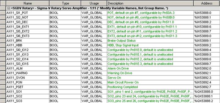
23 1.8.2 Motion axis I/O Addressing Global variable groups are automatically added to the global variable list when the Hardware Configuration is saved. The following groups and their associated hardware addresses (for all 16 axes) are provided for reference. Variable group are automatically created for the following motion axis types: 1. Servo 2. Variable Frequency Drive 3. Stepper MotionWorks IEC Hardware Configuration

24 Applicability of specific variables will depend on the hardware support for such features. Please refer to the Sigma-5 manual for further details of individual inputs / outputs and their allocations : SIEPS (section 3.2) MotionWorks IEC Hardware Configuration


25 MotionWorks IEC Hardware Configuration
26 MotionWorks IEC Hardware Configuration

27 MotionWorks IEC Hardware Configuration


28 MotionWorks IEC Hardware Configuration

29 1.8.3 Limits Set the soft position, torque, and velocity limits for the application. The Yaskawa system provides some redundancy for torque and velocity limits. In addition to the Servopack speed and torque limits shown below (Pn402, 403, and 407, the MPiec controller can limit position, speed and torque via parameters settable by MC_WriteParameter. Please check the PLCopen help documentation for details. MotionWorks IEC Hardware Configuration


30 1.8.4 Servo Tuning Please refer to the following tuning documents on 1. Tuning for minimizing trajectory following error: AN.MCD Sigma-5 manual: SIEPS (section 5.) MotionWorks IEC Hardware Configuration

31 1.8.5 Performing a Test Move Warning: Be sure to safeguard the machine during the Test Move operation! Use a hardwired E-Stop function in case of unexpected operation. The IEC application program must be stopped using the resource dialog window before using the test move function. MotionWorks IEC Hardware Configuration
32 Direction Select from forward only, reverse only, and forward & reverse motion. Distance User Units Accel/Decel User Units/s 2 Delay Time ms Speed User Units/s Cycles Quantity Motion Alarms The Alarms tab shows alarm history related to the selected axis. The alarms displayed here are the same alarms available from the web server or the MC_ReadAxisError and function block. Each alarm consists of two 16 bit values; an AlarmClass and AlarmID. The following AlarmClasses refer to alarms originating on devices other than the MPiec controller: 0x3302=SGDH 0x3303=SGDS or SGDV 0x3312=VFD 0x3313=Generic Stepper 0x3314=Oriental Stepper 0x3315=MyComStepper MotionWorks IEC Hardware Configuration
33 For each of the AlarmClasses listed above, the AlarmID is the alarm code generated by the device. For more information regarding Servopack alarms, refer to the following manuals: Sigma II with NS115: SIEP C , see section 9.3 Sigma III: YEA-SIA-S800-11, see section Sigma-5 with rotary motor: SIEPS , see Section 6.1 Sigma-5 with linear motor: SIEPS , see Section 6.1 For more information regarding Variable Frequency Drive alarms, refer to the following manuals: A1000: SIEP C , see section 6.3 V1000: SIEP C , see section 6.5 If the AlarmClass is any other value, check the Controller AlarmID List. MotionWorks IEC Hardware Configuration

34 1.8.7 Remote I/O Devices MECHATROLINK I/O devices, such as those provided by Yaskawa and Phoenix Contact can be connected to the MP2300Siec or MP2310iec controller. Once the remote I/O device has been added and saved in the Hardware Configuration, a new group will be automatically created in the Global Variables grid. Configuring a Phoenix Remote I/O device A Phoenix Remote I/O Mapping Tool is available to help configure IL MII BK units. Instructions for the mapping tool and creating variable sets are available in this document: AN.MP2000iec.10. MotionWorks IEC Hardware Configuration
35 More information on the IL MII BK units can be obtained from the Phoenix Contact Bus Coupler Manual from Application Notes Phoenix IB IL PWM 2 PAC configuration for pulse/step and direction output : AN.MCD Setting User Units When one of the motion axes is selected on the configuration tree, click on its Configuration tab to set the user unit parameters. Changes to user units will only take effect after a power cycle. Rotary Motors: The default User Unit for rotary motors is 1.0 = one motor revolution. This User Unit configuration in the controller is independent of the encoder resolution. Encoder resolution is read from the drive and is factored at run time by the controller firmware. Linear Motors: The default User Unit for linear motors is 1.0 = one millimeter, however Pn282 must be set correctly for the linear encoder scale used. Typically, the linear scale pitch is 20 microns. MotionWorks IEC Hardware Configuration

36 Warning: If user unit parameters are changed after MC_SetPosition has been executed to store an absolute encoder position offset, the position value will be incorrect after power cycle. Use MC_SetPosition again to calibrate the axis after changing the User Unit parameters. Example 1: MotionWorks IEC Hardware Configuration
37 1.8.9 All Parameters This tab displays a list of all parameters related to the selected axis, including both controller and drive side parameters. If the Hardware Configuration is online with the controller, the current value column displays parameters in the amplifier (Pns) and controller parameters (non Pn parameters). This page can be used to edit both amplifier parameters and controller parameters. Color Legend: Blue = Parameters that are forced to a specific value as shown in the grid. Do not alter these parameters in the amplifier using other means, such as a digital operator, or the Y_WriteParameter function block. If blue parameters are changed using other methods, improper operation may result. Note: In some applications, it may be advantageous to change the gear ratio Pns 20E and 210 in the amplifier to account for situations where the physical ratio may be changed as part of the machine design. For example, assume the User Units are set for a 360 degree rotary cycle, and the gear ratio setting on the Configuration tab is 5:1. If later the gear box is changed to 10:1, Pn 20E and 210 can be set to reflect an additional 2:1 change in physical ratio, but the controller will still operate using 0 ~ 360 degrees per cycle of the machine. Grey = Parameters that cannot be changed by the Hardware Configuration. MotionWorks IEC Hardware Configuration

38 S-Curve Settings The configuration page allows the user to select whether an axis is to be used in rotary mode or in linear mode. A rotary mode axis is one which has a positioning system that is based on a modulus called machine cycle. For example, an indexing table that travels in one direction only with a finite machine cycle is a rotary axis. A ball screw system can be defined as a linear axis. For rotary axes, the user should specify a machine cycle. Refer to section on how to set user units in the hardware configuration. S-Curve functionality S-Curve functionality for discrete motion profiles is available starting in firmware version by enabling the moving average filter function. To use the moving average filter, enable it in the configuration tab for the motion axis. Once enabled in the Hardware Configuration and saved in the controller, the feature cab be toggled off and on in the IEC application MotionWorks IEC Hardware Configuration
. (0 excluded). If the Moving Average filter time constant is set to 0.")
39 using MC_WriteBoolParameter and parameter number The filter time constant (parameter 1301) can also be specified in the same tab. The filter is implemented as a lag filter as shown below. The moving average filter limits are [0,5). (0 excluded). If the Moving Average filter time constant is set to 0.1 seconds and the MECHATROLINK/DPRAM update rate is set to 2 ms, the moving average will provide a filter of 50 data points (50 data points in 100 ms). An example of a move profile with the Moving Average Filter applied is shown below. The logic analyzer plot below shows the effect of a 0.1 s moving average filter set up. The logic analyzer is synchronized with a 2 ms application task. It can be seen that the filtered profile (in red) settles to steady state 50 scans after the commanded profile (in blue). Since each scan is 2 ms in time, 50 scans show 100ms in time. Thus it can be seen that a 0.1s moving average filter set up generates an s curve velocity profile where the filtered velocity will lag the commanded trapezoidal profile by 0.1 seconds. MotionWorks IEC Hardware Configuration
 Configuration of a fully closed module on a Sigma-5 Servopack is possible by setting parameters on the 'Dual Encoder' and 'Configuration' tab. 1.")
40 Commanded velocity in blue (Parameter 1011). Post S - curve commanded velocity in red (Parameter 1021) Note: For rotary mode applications using the Moving Average Filter, use firmware or greater Dual Encoder (Full Closed Loop) Configuration of a fully closed module on a Sigma-5 Servopack is possible by setting parameters on the 'Dual Encoder' and 'Configuration' tab. 1. Set Pn20A, Number of External Scale Pitch. 2. Set Pn002.2 = 1 (Use absolute encoder as incremental.) 3. Set Pn002.3 to 1 or 3 depending on the direction of the fully closed encoder. MotionWorks IEC Hardware Configuration
41 4. Increase Pn51B, the allowable deviation between motor and load positions that will trigger an alarm. The proper value is application dependant. 5. Set Pn22A.3 = 0 (Use motor encoder speed for speed feedback (Recommended.) NOTES: Yaskawa recommends selecting an encoder resolution that closely matches the encoder counts per user unit of the Sigma-5 servo. (Less than 20:1 pulse count difference.) High resolution will improve the effectiveness of the powerful auto-tuning algorithms in the Sigma-5 Servopack. The MPiec controller forces the electronic gear ratio (Pn20E and Pn210) to be unity (1:1). Use the Gear Ratio values on the Configuration tab as shown below. Please refer to the Sigma-5 manual for details about individual Servopack Pns: SIEPS (Section 8) Example 1: Assume a ball screw system with a lead of 120 mm. There is gear reduction of 9:1, and the external encoder sine wave pitch = 20 um. Pn20A = (120mm/1 rev of gearbox) x (1rev of gearbox / 9 rev of motor) x (pitch / 0.02 mm) = 667 pitch / rev. The configuration settings for this example are shown in the figure below. MotionWorks IEC Hardware Configuration

.")
42 A snap shot of the dual encoder tab is shown below Example 2: Assume a fully closed loop system with the following encoder parameters: One rev of the motor shaft = mm at the load. Fully Closed Encoder, wheel diameter = 1.25 inches. Encoder resolution = 5000 sine waves / rev. 8 bit serial converter (256 pulses per cycle). MotionWorks IEC Hardware Configuration

43 Therefore, the number of pulses in one rev of the external encoder = 5000 x 256 = pulses / rev. The distance covered in one revolution of the fully closed encoder = 1.25 x Pi x 25.4 = 99.7 mm mm --> pulses. 1 mm --> /99.7 = pulses. The configuration settings for this example are shown in the figure below. Pn20A = The number of external encoder pitches per rev of the motor. 1 rev of motor = mm. Therefore, (99.7/50.265) revs of the motor = 99.7 mm (distance for one rev of the fully closed encoder) 99.7/ revs of the motor = 5000 pitches. MotionWorks IEC Hardware Configuration

44 Therefore, 1 rev of the motor = (5000 / (99.7/50.265)) = 2513 pitches / rev of motor. Pn20A = 2513 pitches / rev of the motor. MotionWorks IEC Hardware Configuration
45 1.9 Ethernet Communications Ethernet Connections Overview The controller can operate as an EtherNet/IP scanner and adapter, a Modbus/TCP client (master) and server (slave), and deliver OPC data simultaneously. Global Variable Groups created when EthetNet/IP adapter and MODBUS TCP server (slave) communication capabilities are enabled in the Hardware Configuration. MotionWorks IEC Hardware Configuration
46 1.9.0 Connecting to the Controller The project IP address is located under the TCP/IP Settings in the Configuration Tree. The IP Address is cross-linked with the IP Address in the Hardware Tab of the Project. All programming tools can communicate simultaneously with the controller (MotionWorks IEC, Hardware Configuration, and web server.) A color-coded indicator in the upper right corner of the window indicates the connection status with a red or green background and displaying the text Online or Offline. MotionWorks IEC uses the following Ethernet ports to communicate with the controller hardware. Certain firewall implementations may block these ports, and prohibit communication. An easy way to test for this is a network Ping, or if communication is possible via the web server, but not MotionWorks IEC. Communication Method Port Number MotionWorks IEC Hardware Configuration 4040 Web Server 80 Ethernet/IP (Implicit Messaging) 2222 Ethernet/IP (Explicit Messaging) Modbus/TCP 502 OPC Server MotionWorks IEC Hardware Configuration
47 Application Note Setup for remote EtherNet/IP connections using Routers: AN.MP2000iec Ethernet Connections Overview The controller can operate as an EtherNet/IP scanner and adapter, a Modbus/TCP client (master) and server (slave), and deliver OPC data simultaneously. MotionWorks IEC Hardware Configuration
 to Communicate to the Controller via Modbus/TCP Any MPiec controller can be configured as a MODBUS TCP server (slave) if the user enables the controller as a MODBUS slave in")
48 Global Variable Groups created when EthetNet/IP adapter and MODBUS TCP server (slave) communication capabilities are enabled in the Hardware Configuration Using an HMI (Master) to Communicate to the Controller via Modbus/TCP Any MPiec controller can be configured as a MODBUS TCP server (slave) if the user enables the controller as a MODBUS slave in the Hardware Configuration, saves and cycles power on the controller. MotionWorks IEC Hardware Configuration
49 The Modbus memory map for an MPiec controller when configured as a server (slave) is shown in the figure below. Note that by default, function codes 01 and 03 return data that was sent to the controller from the master and do not reflect data from the Global Variables in the IEC application program. If 'Add Holding Register Outputs' is enabled, the IEC application program can write into MODBUS memory register from as shown in the figure below If the master requires a Device ID setting for the server, the MPiec controllers have a device ID of "1". Other Modbus Driver features: The Modbus memory is copied to the Global Variables at the task update rate as configured by the user in the Hardware Configuration. Maximum number of clients on the network: Tested 3 clients polling an MPiec controller simultaneously. Modbus coil 1 equates to the Global Variable at %IX coils are available. Modbus register equates to the Global Variable at %IW registers are available. Modbus input equates to the Global Variable at %QX inputs are available. Modbus register equates to the Global Variable at %QW registers are available. MotionWorks IEC Hardware Configuration


50 The figure below shows the relationship between Modbus registers and IEC application memory. Memory map for Modbus memory when the controller is configured a server / slave. The following groups are automatically created in the Global Variables worksheet when the controller is configured as a MODBUS server. MotionWorks IEC Hardware Configuration
51 Selected Modbus clients and related Application Notes available on : Red Lion HMI: AN.MCD Maple Systems HMI: AN.MP2000iec.06 Yaskawa MP2000: AN.MP AB PanelView: AN.MP2000iec.02, E Learning Video: elv.mp2000iec.01.iectopvplushmi Phoenix HMI: AN.MP2000iec.05 Pro-face: AN.MCD DigiOne IAP serial to Ethernet converter: AN.MCD Adding a Modbus Server/Slave Device The MPiec controller can communicate with up to 20 unique IP addresses simultaneously using Modbus TCP. A maximum of 20 data blocks of various function codes can be configured if necessary. The minimum poll period or update interval is 4 ms (+4 ms tolerance.) Note that MODBUS TCP is not a deterministic protocol. Setting a very fast update interval is not recommended because it will increase the load on the CPU. Fast updates and high priorities should be allocated based on application requirements) MotionWorks IEC Hardware Configuration

52 Supported Modbus Function Codes: Function Code Description Modbus Address Range (On Slave) 1 Read Coils to Read Inputs to Read Holding Registers to Read Input Registers to Write Single Coil to Write Single Register to Write Multiple Registers to Step 1: Launch the Hardware Configuration Step 2: Right click on the Configuration tree on the Modbus/TCP item. MotionWorks IEC Hardware Configuration


53 Step 3: The Add Modbus TCP Device window is shown below. Enter a name for the slave device, IP address, status variable name, application task whose update rate will determine the rate at which MODBUS data is updated in the application and update interval. The Status Variable will be automatically entered in the Global Variables section of the IEC Programming Environment. The Status Variable is a WORD. This variable will indicate the status of the connection. Details are described below. Step 4: After the device details are added, the MODBUS slave device will be displayed in the configuration tree. MotionWorks IEC Hardware Configuration
54 Step 5: Click on the new Modbus Device in the Configuration tree at the left of the screen. Locate the hyperlink at the lower right of the screen to "Add Data Blocks" to the device. Select a name to be associated with the function code. For example, if the device is remote I/O, name the I/O Group Outputs for example. There is a seven-character limitation on the I/O Group name. The Starting Address is dependent on the remote device. Consult the documentation for the remote device to understand the register offset required to access its functions. Click on the Local Address Range link to enter the IEC Global variable's address range for this I/O group. Enter the starting address and number of elements. The used address ranges will assist the programmer in deciding which IEC address to use as starting address. MotionWorks IEC Hardware Configuration


55 The starting address field is the offset that will be used in the MODBUS slave for the memory area. For example, in the figure shown below, %QW43008 will be mapped to MODBUS register in the server/slave device. MotionWorks IEC Hardware Configuration

56 Step 6: When finished entering data blocks, Save the Configuration. This will create the global memory I/O Group in the IEC Programming Environment. View of the Global Variables list. Click the Hardware tab in the Project Tree or use the 'View' menu to access. Note the status variable has been created under an input section for this Modbus device even though no input-type function codes were configured. Step 7: Open the Global Variables list. Right click on the I/O group header to Insert Variable. This variable can either be a BOOL, WORD, or any other data type that fits the usage within the program. For example, 16 output bits can be defined as one WORD, and in the program, the 4th bit can be accessed as follows: MYWORD.X3. Another example would be 16 individual BOOL variables with unique names. Inserting a variable into the Modbus group. The memory area for this Modbus device is shown in the Group Heading. Bytes %QB %QB43207 are allocated for the Modbus output registers. Enter the proper memory address for the Modbus memory. If the first bit of the register QB43008 needs to be accessed, enter %QX If two bytes QB43008 and QB43009 need to be accessed, it can be done using %QW43008 where W stands for WORD. MotionWorks IEC Hardware Configuration
57 Any IEC data type can be transmitted or requested from the remote device, provided the data is interpreted as the same type on the other side. To determine the memory area allocated for the Modbus connection, look in the MotionWorks IEC s IO_Configuration window in the Hardware section of the Project Tree Window. Note: Care should be taken to understand and set the timeout period on the server (slave) driver code. The recommended time out period for server driver code is TO > update interval * # of data blocks. One data block is polled per update interval set in the client (master). For example if the client has four data blocks configured for a particular server with a 50 ms poll period (update interval), the first data block is polled first. After 50 ms the second data block is polled. 50 ms after the second data block, the third data block is polled and so on. The first data block is polled a second time 200 ms after it was polled the previous time as shown in the figure below MotionWorks IEC Hardware Configuration
58 Modbus TCP Status Variable This variable reflects the connection status. It can be used in the application program to determine if the connection to the remote device is active and the data is valid. The status WORD can be compared to 16#1000, which means that the connection is good. If bits 0 or 1 are on, the connection is not active, and the controller is attempting to reconnect to the remote device. The status variable is only available when the MPiec controller is the client or master of remote devices. NOTE: If the status variable has a value of zero as observed in the Global Variables list, the controller may not be running the application program. MotionWorks IEC Hardware Configuration
 Name Meaning 01 Illegal Function The function code received in the query is not an allowable action for the server (or slave).")
59 Figure 7: Modbus status WORD Modbus errors in the lower byte of the status variable ONLY if the Application Error bit is TRUE. Modbus Exception Codes Code (In lower byte of the status variable) Name Meaning 01 Illegal Function The function code received in the query is not an allowable action for the server (or slave). This may be because the function code is only applicable to newer devices, and was not implemented in the unit selected. It could also indicate that the server (or slave) is in the wrong state to process a request of this MotionWorks IEC Hardware Configuration
60 type, for example because it is not configured and is being asked to return register values. 02 Illegal Data Address The data address received in the query is not an allowable address for the server (or slave). More specifically, the combination of reference number and transfer length is invalid. For a controller with 100 registers, the PDU addresses the first register as 0, and the last one as 99. If a request is submitted with a starting register address of 96 and a quantity of registers of 4, then this request will successfully operate (address-wise at least) on registers 96, 97, 98, and 99. If a request is submitted with a starting register address of 96 and a quantity of registers of 5, then this request will fail with Exception Code 0x02 Illegal Data Address since it attempts to operate on registers 96, 97, 98, 99 and 100, and there is no register with address Illegal Data Value A value contained in the query data field is not an allowable value for server (or slave). This indicates a fault in the structure of the remainder of a complex request, such as that the implied length is incorrect. It specifically does NOT mean that a data item submitted for storage in a register has a value outside the expectation of the application program, MotionWorks IEC Hardware Configuration
61 since the MODBUS protocol is unaware of the significance of any particular value of any particular register. 04 Slave Device Failure An unrecoverable error occurred while the server (or slave) was attempting to perform the requested action. 05 Acknowledge Specialized use in conjunction with programming commands. The server (or slave) has accepted the request and is processing it, but a long duration of time will be required to do so. This response is returned to prevent a timeout error from occurring in the client (or master). The client or master) can next issue a Poll Program Complete message to determine if processing is completed. 06 Slave Device Busy Specialized use in conjunction with programming commands. The server (or slave) is engaged in processing a long duration program command. The client (or master) should re transmit the message later when the server (or slave) is free. 08 Memory Parity Error Specialized use in conjunction with function codes 20 and 21 and reference type 6, to indicate that the extended file area failed to pass a consistency check. The server (or slave) attempted to read record file, but MotionWorks IEC Hardware Configuration
62 detected a parity error in the memory. The client (or master) can retry the request, but service may be required on the server (or slave) device. 0A Gateway Path Unavailable Specialized use in conjunction with gateways. It indicates that the gateway was unable to allocate an internal communication path from the input port to the output port for processing the request. Usually means that the gateway is mis configured or overloaded. 0B Gateway Target Device Failed to Respond Specialized use in conjunction with gateways. It indicates that no response was obtained from the target device. Usually means that the device is not present on the network. Note: Do not delete automatically created variables or groups. If you must delete a group, be sure to delete the group header (an all of its variables) and the group name as listed under IO_Configuration in the Hardware tab. These two items must remain in sync for project to compile properly Selected MODBUS Servers and Related Application Notes: Phoenix MODBUS I/O: AN.MCD Wago I/O module: elv.motionworksiec.01.modbusslave MotionWorks IEC Hardware Configuration

63 1.9.4 Using an EtherNet/IP Scanner to Communicate to the MPiec Controller as an Adapter 12 pre-configured instances are defined for input and output. The preconfigured instances are listed below. Each instance can be enabled or disabled individually based on application requirements. The following diagram shows the groups with memory mappings from the Global Variables sheet in MotionWorks IEC when all input and output instances have been enabled in the MPiec Hardware Configuration. Note: The exact byte size of the instance must be configured on the Scanner side. (The entire 128-byte or 256-byte block must be transferred even if less data is required.) The controller will automatically respond to incoming EtherNet/IP messages from Scanners requesting to read or write data of the predefined instances. Note: The scanner must configure both an input and output assembly. If the application does not require any data from the MPiec controller, use assembly 128 with a size of zero and set the "Use Run/Idle" checkbox to satisfy this requirement. MotionWorks IEC Hardware Configuration

64 Global Variable Groups created when EtherNet/IP adapter communication capabilities are enabled in the Hardware Configuration. MotionWorks IEC Hardware Configuration

65 The following diagram shows the relationship of Ethernet/IP instances to Global Variable mapping. Application Notes for selected EtherNet/IP scanner devices: AB MicroLogix: AN.MCD AB ControlLogix: AN.MCD AB CompactLogix: AN.MCD AB SLC 5/05: AN.MP2000iec.01 Set up for remote EtherNet/IP connection using routers: AN.MP2000iec.04 MotionWorks IEC Hardware Configuration
66 1.9.5 Adding an Ethernet/IP Adapter Adding an Ethernet/IP Adapter EtherNet/IP data is referred to as an Instance. Each device manufacturer defines the type of data contained and the instances supported. Refer to the specific adapter documentation for details regarding successful communication. The MPiec controllers can communicate with up to 20 unique IP addresses simultaneously using the EtherNet/IP protocol. Explicit Messaging is supported by using the Explict_Message function block provided in the Yaskawa Toolbox v202 or higher. Explicit Messaging does not require setup in the Hardware Configuration. The minimum poll period or update interval is 2 ms. (Note that EtherNet/IP is not a deterministic protocol. Setting a very fast update interval is not recommended because it will increase the load on the CPU. Fast updates and high priorities should be allocated based on application requirements.) MotionWorks IEC Hardware Configuration

67 Steps to add an EtherNet/IP adapter: Step 1: Launch the Hardware Configuration Step 2: Right click on the Configuration tree on the Ethernet/IP item and select 'Add Device'. MotionWorks IEC Hardware Configuration

68 Step 3: Enter the Adapter details in the "Add EtherNet/IP" Adapter dialog box. MotionWorks IEC Hardware Configuration

69 Step 4: Once the adapter device has been configured, the adapter device is shown in the configuration tree as shown below. Step 5: Click on the adapter device and add I/O assembly instances. Please refer to the adapter device manual for details regarding instance numbers and sizes. Some adapter devices require "Configuration" assembly instances. Step 6: Save the Configuration. This will create the global memory I/O Group in the IEC Programming Environment. Step 7: Switch to the Online mode and Send the Offline Configuration. Save the configuration to the controller and cycle power. The controller will start to communicate with the adapter device. MotionWorks IEC Hardware Configuration
70 Step 8: Open the Global Variables list. Right click on the I/O group header to Insert Variable. Variables can be any data type that fits the usage within the program. For example, a structure can be created to match the data size of the instance as described in the documentation for the adapter device. NOTE: When creating user defined datatype STRUCTs, the minimum amount of space a single data element will occupy is a BYTE, so it is not possible to create BOOL type data in the STRUCT that will match the memory map of the EtherNet/IP instance. Ethernet/IP Status Variable This variable reflects the connection status. It can be used in the IEC application program to determine if the connection to the remote device is active and the data is valid. The status WORD can be compared to 16#1000, which means that the connection is good. If bits 0 or 1 are on, the connection is not active, and the controller is attempting to reconnect to the remote device. This status variable is only available when the MPiec controller is the client or master of a remote device. NOTE: If the status variable has a value of zero as observed in the Global Variables list, the controller may not be running the IEC application program. MotionWorks IEC Hardware Configuration
 0x100 Connection in Use or Duplicate Forward Open 0x103 Transport Class and Trigger combination not supported 0x106 Ownership Conflict: There is another master communicating to this")
71 Lower 3 Nibbles Description 0x001 Unable to connect (timeout) 0x002 I/O Timeout 0x003 Reconnect In Progress 0x004 Connection Failed (invalid response from server) 0x005 Connection Failed (out of resources) 0x100 Connection in Use or Duplicate Forward Open 0x103 Transport Class and Trigger combination not supported 0x106 Ownership Conflict: There is another master communicating to this adapter with an exclusive ownership setting. 0x107 Connection not found at target application 0x108 Invalid Connection Type. Indicates a problem with MotionWorks IEC Hardware Configuration
72 Lower 3 Nibbles Description either the Connection Type or Priority of the Connection. 0x109 Invalid Connection Size 0x110 Device not configured 0x111 RPI not supported. May also indicate problem with connection time-out multiplier, or production inhibit time. 0x113 Connection Manager cannot support any more connections 0x114 Either the Vendor Id or the Product Code in the key segment did not match the device 0x115 Product Type in the key segment did not match the device 0x116 Major or Minor Revision information in the key segment did not match the device 0x117 Invalid Connection Point 0x118 0x119 Invalid Configuration Format Connection request fails since there is no controlling connection currently open. MotionWorks IEC Hardware Configuration
73 Lower 3 Nibbles Description 0x11A Target Application cannot support any more connections 0x11B RPI is smaller than the Production Inhibit Time. 0x203 Connection cannot be closed since the connection has timed out 0x204 Unconnected Send timed out waiting for a response 0x205 Parameter Error in Unconnected Send Service 0x206 Message too large for Unconnected message service 0x207 Unconnected acknowledge without reply 0x301 No buffer memory available 0x302 Network Bandwidth not available for data 0x303 No Tag filters available 0x304 Not Configured to send real-time data 0x311 Port specified in Port Segment Not Available 0x312 Link Address specified in Port Segment Not Available 0x315 Invalid Segment Type or Segment Value in Path. An unsupported instance may be requested from the MotionWorks IEC Hardware Configuration
74 Lower 3 Nibbles Description adapter. 0x316 Path and Connection not equal in close 0x317 Either Segment not present or Encoded Value in Network Segment is invalid. 0x318 Link Address to Self Invalid 0x319 Resources on Secondary Unavailable 0x31A Connection already established 0x31B Direct connection already established 0x31C Miscellaneous 0x31D Redundant connection mismatch 0x31E No more consumer resources available in the producing module 0x31F No connection resources exist for target path Note: Do not delete automatically created variables or groups. If you must delete a group, be sure to delete the group header (an all of its variables) and the group name as listed under IO_Configuration in the Hardware tab. These two items must remain in sync for project to compile properly. MotionWorks IEC Hardware Configuration

75 Application Notes/Example Code on selected EtherNet/IP adapter devices Please refer to subsection for configurations required for selected EtherNet/IP adapter devices. Motoman NX100: AN.MCD Yaskawa V1000: EC.V SMC pneumatics: AN.MP2000iec.03 Numatics: AN.MCD DeviceNet slaves: PN.MCD Adapter Settings for Selected Products Allen Bradley Armor Block IO Beckhoff IO MotionWorks IEC Hardware Configuration


76 Cognex Vision System Phoenix EtherNet/IP module MotionWorks IEC Hardware Configuration


77 RTA Gateway SICK Vision Sensor SMC IO MotionWorks IEC Hardware Configuration

78 Turck IO Yaskawa VFD MotionWorks IEC Hardware Configuration


79 Wago Coupler MotionWorks IEC Hardware Configuration


80 1.9.6 OPC Server By default, all global variables are transmitted as OPC data. To disable this feature, click the hardware tab, right-click the resource folder, and select Settings. (See figure below) OPC Configuration MotionWorks IEC Hardware Configuration


81 Any data in the application program can be set as OPC data by simply clicking the checkbox in the variable definition screen in the IEC development environment. Variable Definition Window OPC Server Configurator Application Notes Phoenix HMI: AN.MP2000iec.08 MotionWorks IEC Hardware Configuration
82 1.10 External Encoders Option cards LIO-01, LIO-02, and LIO-06 have an encoder input available for use with the PLCopen function blocks. When any of these cards are configured, external encoder functionality is available. To use the encoder, check the 'Enable External Encoder' selection and identify the logical axis number. Use the logical axis number in the IEC application as the AXIS_REF.AxisNum value when referring to the external encoder axis. Changes to the user unit parameters will not take effect until power is cycled. MotionWorks IEC Hardware Configuration
 Set the Pulse Count Mode MotionWorks IEC Hardware Configuration 2013-03-26 80")
83 Steps to configure an external encoder 1) Enable the External Encoder 2) Set User Units 3) Set Load Type 4) Set the Encoder Resolution 5) Set the Pulse Count Mode MotionWorks IEC Hardware Configuration
 Up/Down (One channel indicates forward, the other channel indicates reverse.")
84 Three pulse counting methods are supported: Sign (One channel counts, the other indicates the direction.) Up/Down (One channel indicates forward, the other channel indicates reverse.) A/B (Quadrature) This section describes the details on each pulse counting method: MotionWorks IEC Hardware Configuration
85 MotionWorks IEC Hardware Configuration
 or through the Web Server's Machine Operations page.")
86 AXIS_REF assignment in IEC Application code: Once the configuration is complete and power cycled, the external encoder can be verified via the IEC Application (using the MC_ReadActualPosition function block) or through the Web Server's Machine Operations page. MotionWorks IEC Hardware Configuration


87 1.11 Option Slots Each slot in the controller can optionally contain a module, or remain empty. The following option cards are supported: MotionWorks IEC Hardware Configuration
88 Global variables for the following remote I/O devices with a fixed number of I/O will automatically be entered in the Global Variables grid of the IEC Programming Environment when the user presses 'Save' in the Hardware Configuration: AO-01 AI-01 DO-01 LIO-01 LIO-02 LIO-04 LIO-05 LIO-06 Note: Do not delete automatically created variables or groups. If you must delete a group, be sure to delete the group header (and all of its variables) and the group name as listed in the Project Tree Window's 'IO_Configuration' in the Hardware tab, then press Save in the Hardware Configuration once again to refresh. These two items (Group Name and group listing in IO_Configuration) must remain in sync for project to compile and run properly. MotionWorks IEC Hardware Configuration
89 1.12 Task Priority Planning The following table serves as a guide to architect the execution priority of the various parts of the application program. This table is only applicable to programs that utilize MotionWorks IEC Professional. MotionWorks IEC Express only supports 1 task. Controller Task Overall Priority Note 0 System Tasks with higher priority than IEC Tasks System Tasks System Tasks with higher priority than IEC Tasks System Tasks with higher priority than IEC Tasks 21 Highest Priority IEC Application Task - Priority 0 42 These PLC Tasks are not interrupted by network activity MotionWorks IEC Hardware Configuration
90 IEC Application Task - Priority 1 43 IEC Application Task - Priority 2 44 IEC Application Task - Priority 3 45 IEC Application Task - Priority 4 46 IEC Application Task - Priority 5 47 IEC Application Task - Priority 6 48 PLC Tasks, round robin with MECHATROLINK Work Task MECHATROLINK Work Task 48 MECHATROLINK alarm polling Task, reads all alarms from drives Alarm Task 48 Executes lower priority alarm handlers IEC Application Task - Priority 7 49 PLC Tasks interrupted by MECHATROLINK work q IEC Application Task - Priority 8 50 PLC Tasks interrupted by MECHATROLINK work q; round robin with inbound net activity Network Communication Task 50 All inbound traffic comes in at this Priority. Outbound is handled by the driver Tasks IEC Application Task - Priority 9 51 These PLC Tasks interrupted by network, use for IEC Application Task - Priority custom network driver IEC Application Task - Priority This PLC Task is interrupted by network, round robin with EIP Communication Task E/IP Communication Task 53 EthernetIP communication driver MotionWorks IEC Hardware Configuration
91 IEC Application Task - Priority IEC Application Task - Priority These PLC Tasks interrupted by network and EIP IEC Application Task - Priority This PLC Task is interrupted by network and EIP; Round robin with Modbus TCP Task Modbus TCP Communication Task 56 Modbus communication driver IEC Application Task - Priority This PLC Task is interrupted by Modbus and EIP; but not interrupted by OPC or RMI Lowest Priority IEC Application Task - Priority Interrupted by Modbus and EIP; not OPC or RMI IEC Application Idle Task 60 MotionWorks IEC "Default" Task. ProConOS Communication Task 70 ProConOS Communication Task 70 ProConOS Communication Task 70 ProConOS Communication Task 70 ProConOS Task for Application "Download Changes" 73 PLC communication: OPC and MotionWorks IEC debug ProConOS Task for MotionWorks IEC communication 74 ProConOS debugging Task 76 ProConOS Task for managing code 77 ProConOS Task for Run/Stop mode 78 System Tasks with lower priority 80 Applet / Hardware Configuration / Web MotionWorks IEC Hardware Configuration
92 than IEC Tasks 81 Server communication System Tasks with lower priority than IEC Tasks Color Codes: Hardware Operating System Tasks Hardware Operating System Tasks IEC Operating System Tasks IEC Application Tasks Network Communication Driver (Incoming Traffic) Tasks for Hardware Configuration Network Communication Tasks MotionWorks IEC Hardware Configuration
93 1.13 Creating an Archive.ZIP In MotionWorks IEC version and greater, a new feature was added to create an Archive.ZIP from an icon on the Configuration toolbar shown below. Click the Icon on the toolbar to create an Archive.ZIP. This feature is intended to allow users to make minor changes to completed applications and deploy an updated Archive.ZIP to a machine in the field. Warning: The user must ensure that the offline Hardware Configuration parameters are valid for the machine in which the Archive.ZIP will be installed. The Archive.ZIP file contains all necessary files for the application and will overwrite the XML configuration files, with the exception of any user files such as cam or csv. If user files are required for the application, it may be necessary to instruct the Archive.ZIP installer to use the settings as shown below for "Add or Replace Only." MotionWorks IEC Hardware Configuration

94 MotionWorks IEC Hardware Configuration
95 2. Web Server Web Server Overview The Web Server is built into the controller firmware and allows the user to locally or remotely perform various activities. By default, there are two access levels to the controller via the web server; the second level requires a password to access features such as firmware upgrade utilities. Capabilities include: Multiple levels of security. By default, there are some functions available without login, and other that require a password. The default UserName and Password can be edited and additional levels of security can be added by the user. Part number and axis count capability. Firmware version verification and upgrade. Alarm history with time stamp. Basic motion verification via the Machine Operations page. Basic data logging via the Machine operations page. Amplifier parameter read / write, including absolute encoder reset and MECHATROLINK network reset. I/O verification. IP address configuration. Real time clock settings. MotionWorks IEC Hardware Configuration
96 The web server's factory default logins, passwords, and access levels can be changed to create additional security levels. Please refer to AN.MCD for details on how this can be accomplished. Computer Requirements The MPiec Series Controllers support a web server feature that has the following requirements: 1. Sun Microsystems Java Virtual Machine or higher. 2. Internet Explorer 6 or higher. Other browsers such as Mozilla Firefox and Google Chrome will only work if an Internet Explorer compatibility mode is installed. 2.3 Web Server Functionality By default, there are some functions available without login, and other that require a password. The default UserName and Password can be edited and additional levels of security can be added by the user. MotionWorks IEC Hardware Configuration
97 The functions available without logging in are: 1) Welcome Page (displays Firmware version and axis count) 2) Alarm Status 3) Alarm Reference (Common alarms, causes and ways to clear alarms) 4) Alarm History (Alarm IDs with time stamps controller) 5) Axis Grids 6) I/O Grid Additional functions available after the user logs in are: 7) Machine Operations 8) Debugging Output 9) Configuration Sets 10)Ethernet Configuration 11) Set clock 12) Project Archive 13) Update Firmware 14) Initialize SRAM 15) Reboot MotionWorks IEC Hardware Configuration

98 Level 2 (Additional functions) of the controller web server can be accessed using the following login and password. Note that the factory default logins, passwords, and even access levels can be changed and edited to allow OEMS and machine builders create secure MotionWorks IEC Hardware Configuration
99 levels in the controller s web server. Please refer to AN.MCD for details on how this can be accomplished. Level 1 of Web Server Welcome Page The Welcome page opens when the user connects to an MPiec controller using Internet Explorer. Details about the controller s firmware version can be obtained from the web server welcome page. Use the Welcome page to confirm the firmware version, model number, and axis count capability. MotionWorks IEC Hardware Configuration
100 Welcome Page The Welcome page opens when the user connects to an MPiec controller using Internet Explorer. Details about the controller s firmware version can be obtained from the web server welcome page. MotionWorks IEC Hardware Configuration
101 Use the Welcome page to confirm the firmware version, model number, and axis count capability. Alarm Status This page displays current controller and drive alarms from all connected motion axes. Resettable alarms (such as a ServoPack Overspeed alarm A.510) can be cleared using the Clear Alarms button. Certain alarms, such as ServoPack A.C9: Encoder Communication Error require power cycle to be cleared. Check the Sigma manuals for details regarding clearable alarms. MotionWorks IEC Hardware Configuration
 has a value of 16#3302, 16#3303, 16#4302, or 16#4403, then the source of the")

102 Alarm Reference Common amplifier alarms are listed on the Alarm Reference page. If the upper 2 bytes (ErrorClass) has a value of 16#3302, 16#3303, 16#4302, or 16#4403, then the source of the alarm is the Sigma Servopack. Please refer to the following manuals for details regarding Sigma servo amplifier alarms: Sigma II with NS115: SIEPC , see section 9.3 Sigma III: YEA-SIA-S800-11, see section MotionWorks IEC Hardware Configuration
103 Sigma-5 with rotary motor: SIEPS , see Section 6.1 Sigma-5 with linear motor: SIEPS , see Section 6.1 If the upper 2 bytes (ErrorClass) has a value of 16#3312, then the source of the alarm is the variable frequency drive. Please refer to the following manuals for details regarding Variable Frequency Drive alarms: A1000: SIEP C , see section 6.3 V1000: SIEP C , see section 6.5 If the upper 2 bytes (ErrorClass) has a value of 16#3313, 16#3314 or 16#3315, then the source of the alarm is a stepper amplifier. Please refer to the appropriate stepper amplifier documentation for alarm descriptions. Alarm History Alarms are saved in SRAM with a time stamp. This can help in troubleshooting possible failure modes if an axis is down on a machine. It is possible to save the alarm log as an HTM file by pressing the Save button on the Alarm History page. MotionWorks IEC Hardware Configuration


104 Axis Grid The axis grid page provides details about the axes connected to the controller. In the figure shown below, the two axes at nodes 1 and 2 are SGDV servos. Axis 21 is an external encoder available in the LIO card in the controller. MotionWorks IEC Hardware Configuration

105 I/O Grid A sample I/O grid of a MP2300Siec motion control system including an LIO option card and two Sigma Servopacks is shown here. The digital I/O are explained in detail under the I/O tab in the Machine Operations help section. Level 2 of Web Server Machine Operations Feedback position in user units, velocity in user units/sec, and torque feedback (in % of rated torque) can be monitored on the Machine Operations page. Position, velocity, or torque test moves can be performed. Before starting a test move via the web server, ensure that the IEC Application program is not running by either turning off the Run DIP switch on the controller or stopping the PLC from the Resource Dialog box. Also confirm that no Test Move commands from the Hardware Configuration are taking place. Target parameters like position, velocity acceleration and deceleration must be specified. Set the Enable checkbox before the test move is commanded by pressing the MOVE button. MotionWorks IEC Hardware Configuration
106 Machine Operations Feedback position in user units, velocity in user units/sec, and torque feedback (in % of rated torque) can be monitored on the Machine Operations page. Position, velocity, or torque test moves can be performed. Before starting a test move via the web server, ensure that the IEC Application program is not running by either turning off the Run DIP switch on the controller or stopping the PLC from the Resource Dialog box. Also confirm that no Test Move commands from the Hardware Configuration are taking place. Target parameters like position, velocity acceleration and deceleration must be specified. Set the Enable checkbox before the test move is commanded by pressing the MOVE button. MotionWorks IEC Hardware Configuration

107 Machine Operations Alarms The Alarms tab on the Machine Operations page lists all current alarms in the controller and amplifiers. If the alarms listed are clearable without power cycle, the Clear Alarms button will clear the alarms. The Reset ServoNet button will reset MECHATROLINK communications and rediscover all devices on the network. This feature will also soft reboot the amplifiers. MotionWorks IEC Hardware Configuration


108 Data Logs Feedback position, velocity, torque, commanded position, velocity, torque and position error can be recorded at the MECHTROLINK update rate using the Data log function. Start the logging procedure by pressing Start Logging. Options to trigger the data capture and number of data points can be set in this page. MotionWorks IEC Hardware Configuration

 Right click and select Zoom In.")
109 Once the End Trigger condition is satisfied, the log is automatically displayed. The data can be saved as a CSV file (using the Save Log button.) The data log can be zoomed by: 1) Left mouse click and drag diagonally down across the area to be zoomed. 2) Right click and select Zoom In. To clear the zoom, right mouse click and select Clear zoom MotionWorks IEC Hardware Configuration

110 Axis Parameters Select drive parameters are displayed on the Axis Params tab of the Machine Operations page. Drive parameters can be written to the device by editing the values and entering the edited data. Drive Pns All parameters can be read and written from corresponding drives listed in the Drive Pn tab of the Machine Operations page. Edits made to drive parameters can be made permanent (by writing to the drive's flash memory) if the Permanent box is checked. Absolute encoder reset (using Abs Encoder Init) and clearing the multiturn mismatch alarm: A.CC (using Multiturn Reset) can be performed from this tab. The function block Y_ResetAbsoluteEncoder performs the same functions as the buttons on this page. MotionWorks IEC Hardware Configuration
 and the memory being used by the application project running on the controller (1.")

111 Diagnostics The Diagnostics tab shows the total free memory (1.6 MB in the figure below) and the memory being used by the application project running on the controller (1.02 MB in the example shown below) Debugging Output The debugging outputs page window shows a log of events encountered and tasks performed during the latest power up of the controller. For example the list of motion axes and I/O units that were discovered, the communication drivers that were started, the configuration files read, etc. are listed in this log. MotionWorks IEC Hardware Configuration

112 MotionWorks IEC Hardware Configuration

113 Configuration Sets The Configuration Sets page contains a listing of all the XML configuration files on the controller. The disco folder contains files that were created when the controller powered up and discovered devices on the MECHATROLINK network and other I/O connected to the controller. The startup folder is created when the Hardware Configuration is online and saved by the user. This is the only configuration that can be run successfully with an IEC application. This page and the files listed are strictly for troubleshooting purposes and should not be edited by the user. MotionWorks IEC Hardware Configuration

114 Drive Parameters Starting in firmware version 2.2.1, the web server has a new page to send drive parameters to the corresponding MECHATROLINK drives in the system. This feature is useful in machine commissioning operations by eliminating the need to configure the drives with either SigmaWin, DriveWizard, the Hardware Configuration, or the Y_WriteDriveParameters function block. MotionWorks IEC Hardware Configuration

115 Ethernet Configuration The following Ethernet Configuration details of the controller can be identified and set: IP Address(es) Subnet Mask Default Gateway These fields must not be left blank. Versions of the Hardware Configuration before v1.2.3 could not connect to a controller if Ethernet configuration fields were left blank. If the Ethernet configuration is changed, the controller must be rebooted for the new settings to take effect. MotionWorks IEC Hardware Configuration

116 MP2600iec Ethernet Configuration The MP2600iec has two Ethernet connections, Cn11A and Cn11B. Each of these connections are physically separate in the controller hardware, meaning they each have their own MAC addresses, and must be connected to separate networks. This means that the subnet portions of the IP address of each port must be different. Also note that the default gateway is only related to Cn11A, so the subnet mask portion of the default gateway must match the IP address of the Cn11A port. Set Clock Set and view the controller's real time clock. This time will be used for all alarm time stamps, and is also available in the IEC application program via the RTC_S function block from the ProConOS firmware library or the RealTimeClock function block available in the Yaskawa Toolbox. MotionWorks IEC Hardware Configuration
117 Project Archive It is possible to download or upload the complete application image to / from an MPiec controller without using MotionWorks IEC or the Hardware Configuration. A single file called Archive.Zip contains all the Hardware Configuration Data and the IEC Application Program, including any data files that may be used by the application that were downloaded to flash using the Download File button from the MotionWorks IEC Resource Dialog or via HTTP file transfer to the controller. To install an application archive on the controller, follow these steps. 1) Connect to the controller using Internet Explorer. 2) Enter the Login and Password. 3) Under the Maintenance section on the left hand of the screen, click Project Archive 4) Click Browse to locate a previously stored archive.zip file. 5) Click the Upload button to send the file to the controller. It will extract and replace all files shown in the file listing. 6) Reboot is necessary for the configuration and application program to become operable. WARNING: If the application has absolute encoders, the absolute encoder offset stored when the MC_SetPosition function block is executed is not part of the archive.zip. If the archive.zip file is loaded into another controller, and the application uses absolute encoders, axis calibration (homing) must be performed to be sure that the application will operate properly on the new controller. MotionWorks IEC Hardware Configuration

118 Machine Commissioning Note Sending archive.zip to the controller does not send parameters to the MECHATROLINK amplifers. A function block called Y_WriteDriveParameters can be included in the application program, which will send amplifier parameters listed in XML files on the controller to the referenced MECHATROLINK amplifier when executed. Starting in firmware version 2.2.1, it is possible to send the amplifier parameters to the MECHATROLINK amplifiers via the web server. See the Drive Parameters page. MotionWorks IEC Hardware Configuration
119 Update Firmware Firmware should not be upgraded on machines running in production environment unless recommended by an authorized Yaskawa representative. Firmware revisions are available at NOTE: DO NOT EXTRACT THE FILES FROM THE ZIP. THE CONTROLLER WILL EXTRACT THE FILE ITSELF. The controller must be in "Supervisor Mode" before the firmware update can begin. This mode can be entered by either turning on the SUP DIP switch on the front of the unit, or by enabling it via software from the Update Firmware page. Both methods are equivalent, however enabling Supervisor Mode via software is recommended because the mode will automatically be cancelled upon the next reboot. Updating the Firmware: 1. If choosing to use the physical SUP switch, turn it on and reboot the controller. 2. Open the web interface in a web browser and connect to the controller by entering the controller IP Address in the Address field. 3. Select Login from the left menu bar. MotionWorks IEC Hardware Configuration

120 3. Login using the following Login name and password: Controller Login Password MP3200iec Admin MP3200 MP2310iec Admin MP2300S MP2300Siec Admin MP2300S MP2600iec Admin MP2600 MotionWorks IEC Hardware Configuration
121 Note that the factory default Login and passwords may be changed by the user according to the information supplied in product note AN.MCD Select Update Firmware from the left menu: MotionWorks IEC Hardware Configuration


122 5. The firmware update screen will appear: If the physical SUP switch was not enabled before step 1, the page will say the firmware update is prohibited. Click on the enabled via software hyperlink in the text message area. Reboot the controller by clicking on the Reboot Controller button on the update page: 8. After the controller has finished rebooting, the following page will be displayed: MotionWorks IEC Hardware Configuration


123 9. Click on the Update Firmware link in the left menu. 10. Select a firmware.zip file that you wish to load. NOTE: DO NOT EXTRACT THE FILES FROM THE ZIP. THE CONTROLLER WILL EXTRACT THE FILE ITSELF. MotionWorks IEC Hardware Configuration

124 11. Click Browse to locate the file. 12. Click Upload to upload the firmware file to the controller. 13. After the version has been verified, a message box will indicate the version currently in the controller, and the version about to be loaded. 14. Click on the Update button to update the controller firmware. 15. Do not power cycle the controller or attempt to click on any of the menu bar links while the upgrade is taking place! Wait for the page to indicate that the firmware upgrade has completed. MotionWorks IEC Hardware Configuration

125 16. Verify correct version loaded on the controller by clicking Welcome (to refresh) in the left menu bar. Refer to Product Note PN.MCD on for the complete instruction guide. MotionWorks IEC Hardware Configuration
 2.")

126 Initialize SRAM Data that is reset when the SRAM is initialized: 1. Absolute Encoder offsets stored in the controller (by the MC_SetPosition function block.) 2. IEC Global variables marked as 'Retain' data. 3. Alarm history. Reboot The controller can be rebooted from the web server. This function is identical to cycling power. Note that SGDV Servopacks are also 'soft rebooted' when the controller restarts. This will clear any alarms that require power cycling the drive. MotionWorks IEC Hardware Configuration

127 Controller AlarmID List The following is a list of alarm codes that are reported in the Hardware Configuration's Alarms tab or via the Y_ReadAlarm function block. These are non axis specific system alarms. Hex Code Description ErrorClass AxisErrorID ErrorClass+AxisErrorID output from MC_ReadAxisError AlarmID AlarmID output from Y_ReadAlarm motionkernel An alarm task queue was full when a new alarm was posted. This indicates that the task is being starved of execution time or that the system is generating many alarms simultaneously. app The script environment ran out of memory. This is a serious condition because it may prevent further errors from being handled correctly. app An error occurred while running the standard error handler for a general script error. This is a serious condition because it indicates the standard error handler is malfunctioning. app This error should never occur and is included only for completeness. It indicates that an unknown and potentially fatal problem has occurred within the script engine. app A The script task failed to stop cleanly, which may result in unreleased system resources. Error recovery requires the controller be reset. app B The command line task failed to stop cleanly, which may result in unreleased system resources. Error MotionWorks IEC Hardware Configuration
128 Hex Code Description ErrorClass AxisErrorID ErrorClass+AxisErrorID output from MC_ReadAxisError AlarmID AlarmID output from Y_ReadAlarm recovery requires the controller be reset. app The task responsible for publishing events to a remote client failed to stop cleanly, which may result in unreleased system resources. Error recovery requires the controller be reset. app The task responsible for replying to remote clients failed to stop cleanly, which may result in unreleased system resources. Error recovery requires the controller be reset. app The task responsible starting and stopping connections to remote clients failed to stop cleanly, which may result in unreleased system resources. Error recovery requires the controller be reset. app The file system on which the configuration file directory resides could not be read and may be unmounted or corrupted. The system has booted in a minimal configuration mode, and most functionality is limited. If possible, the file system should be recovered or reformatted and new config files uploaded if applicable. app The watchdog timer expired. app A CPU exception occurred. app The firmware files on the controller do not match the expected checksums. app A The manufacturing procedure failed. The controller probably could not fetch the current time from the network. app 140A 0009 Network reset detected multiple Axes connected to the same servo network node. app 140A 000A Network reset detected multiple I/O connected to the same network node. app 140A 0015 Controller memory was corrupted during network reset resulting in a lost logical Axis data structure. app 140A 0016 Controller memory was corrupted during network reset resulting in a lost logical I/O data structure. app 140A 0018 An Abort input specified in the configuration could not be found. The abort condition is considered permanently asserted. No motion is possible until the MotionWorks IEC Hardware Configuration
129 Hex Code Description ErrorClass AxisErrorID ErrorClass+AxisErrorID output from MC_ReadAxisError AlarmID AlarmID output from Y_ReadAlarm I/O configuration can be matched to the abort inputs (restart required). app 140A 0021 Too many events were posted from the system ISR. The motion scan and servo net loop have been shut down. app 140B 0002 The controller ran out of free memory, possibly resulting in an unrecoverable failure. Please reboot the controller. app 140B 0004 The largest free memory block is too small, possibly resulting in an unrecoverable failure. Please reboot the controller. app 140C 1035 The manufacturing data on the controller is invalid. The controller needs to be returned to Yaskawa for reprogramming. Mechatrolink The drive returned an invalid watch dog code indicating a possible dropped communication packet. Mechatrolink The drive failed to return confirmation of last aux command within the default timeout period. Mechatrolink An unrecoverable error occurred during auto configuration. As a result, one or more drives are excluded from the servo network. Mechatrolink Overriding the auto configured axes parameters failed. As a result, one or more drives are excluded from the servo network. Mechatrolink Two or more nodes have the same ID. As a result, all servo network communication has been suspended. Mechatrolink The controller must be the root node on the servo network. All servo network communication has been suspended Mechatrolink The servo network communication device failed to initialize. Servo network communication is not possible. Mechatrolink An error occurred sending command to a node during initialization. The node may not support the configured communications rate. Communication with this node has been prohibited, but communication with other nodes may be possible. Mechatrolink E The drive does not return response packet. MotionWorks IEC Hardware Configuration
130 Hex Code Description ErrorClass AxisErrorID ErrorClass+AxisErrorID output from MC_ReadAxisError AlarmID AlarmID output from Y_ReadAlarm Mechatrolink F Bus reset generation that controller is not demanding. Mechatrolink It receives response with the same channel at the same Iso cycle. Mechatrolink The ID in the response packet is not same to ID of AxisNode. Mechatrolink The data length in the response packet is not same to value of CSR register(send_dsp_data_length) of drive. Mechatrolink The packet type in the response packet is not same S- DSP. Mechatrolink Invalid cycle time has passed with configuration file 'servonet.xml'. As a result, all servo network communication has been suspended. Mechatrolink Node is not found on 1394 network. Mechatrolink Invalid node. Mechatrolink Error matching node IDs. DPRAM Invalid watch dog code from drive DPRAM Aux command confirmation failure DPRAM Auto configuration failed DPRAM Overriding auto configuration failed DPRAM Invalid cyclic check sum from drive DPRAM Invalid watch dog from drive DPRAM Control mode is not supported DPRAM Communication with a node failed during servo network startup motionkernel Controller SRAM battery is low motionkernel The file system failed the integral consistency check. Remedy: Power up the controller in supervisory mode using the SUP switch. Clear the alarm. Turn off the SUP switch. Power cycle the controller. motionkernel The motion kernel didn't request to enable axis. But, the axis is enabled. motionkernel The motion kernel didn't request to disable axis. But, the axis is disabled. motionkernel The encoder position stored in SRAM could not be MotionWorks IEC Hardware Configuration
131 Hex Code Description ErrorClass AxisErrorID ErrorClass+AxisErrorID output from MC_ReadAxisError AlarmID AlarmID output from Y_ReadAlarm validated. The value has been reset. motionkernel Main bus power was disconnected while the axis was enabled. Main power must be restored and this alarm cleared before motion can continue. motionkernel Configuration error: multiple alarm tasks with duplicate priority. motionkernel Configuration error: Alarm task not configured. Using default priority and name. motionkernel Axis Coordinate System: The command position was outside the allowable range for the axis in the positive direction (positive overtravel). The axis may not be moved again until the alarm condition is cleared. After the alarm is cleared, it is permissible to execute a move which brings the axis back toward the allowed region, even though the axis is probably still outside the allowed region. Any move which pulls the axis further away from the allowed region will re-trigger the alarm. motionkernel Axis Coordinate System: The command position was outside the allowable range for the axis in the negative direction (negative overtravel). The axis may not be moved again until the alarm condition is cleared. After the alarm is cleared, it is permissible to execute a move which brings the axis back toward the allowed region, even though the axis is probably still outside the allowed region. Any move which pulls the axis further away from the allowed region will re-trigger the alarm. motionkernel Axis Coordinate System: The command speed was greater than the allowable range for the axis in the positive direction (overspeed). The axis may not be moved again until the alarm condition is cleared. motionkernel Axis Coordinate System: The command speed was greater than the allowable range for the axis in the negative direction (overspeed). The axis may not be moved again until the alarm condition is cleared. motionkernel Axis Coordinate System: The command acceleration was greater than the allowable range for the axis in the MotionWorks IEC Hardware Configuration
132 Hex Code Description ErrorClass AxisErrorID ErrorClass+AxisErrorID output from MC_ReadAxisError AlarmID AlarmID output from Y_ReadAlarm positive direction. The axis may not be moved again until the alarm condition is cleared. motionkernel Axis Coordinate System: The command acceleration was greater than the allowable range for the axis in the negative direction. The axis may not be moved again until the alarm condition is cleared. motionkernel Axis Coordinate System: The command torque was greater than the allowable range for the axis in the positive direction (overtorque). The axis may not be moved again until the alarm condition is cleared. motionkernel Axis Coordinate System: The command torque was greater than the allowable range for the axis in the negative direction (overtorque). The axis may not be moved again until the alarm condition is cleared. motionkernel Joint Coordinate System: The command position was outside the allowable range for the axis in the positive direction (positive overtravel). The axis may not be moved again until the alarm condition is cleared. After the alarm is cleared, it is permissible to execute a move which brings the axis back toward the allowed region, even though the axis is probably still outside the allowed region. Any move which pulls the axis further away from the allowed region will re-trigger the alarm. motionkernel Joint Coordinate System: The command position was outside the allowable range for the axis in the negative direction (negative overtravel). The axis may not be moved again until the alarm condition is cleared. After the alarm is cleared, it is permissible to execute a move which brings the axis back toward the allowed region, even though the axis is probably still outside the allowed region. Any move which pulls the axis further away from the allowed region will re-trigger the alarm. motionkernel Joint Coordinate System: The command speed was greater than the allowable range for the axis in the positive direction (overspeed). The axis may not be moved again until the alarm condition is cleared. motionkernel Joint Coordinate System: The command speed was MotionWorks IEC Hardware Configuration
133 Hex Code Description ErrorClass AxisErrorID ErrorClass+AxisErrorID output from MC_ReadAxisError AlarmID AlarmID output from Y_ReadAlarm greater than the allowable range for the axis in the negative direction (overspeed). The axis may not be moved again until the alarm condition is cleared. motionkernel Joint Coordinate System: The command acceleration was greater than the allowable range for the axis in the positive direction. The axis may not be moved again until the alarm condition is cleared. motionkernel Joint Coordinate System: The command acceleration was greater than the allowable range for the axis in the negative direction. The axis may not be moved again until the alarm condition is cleared. motionkernel Joint Coordinate System: The command torque was greater than the allowable range for the axis in the positive direction (overtorque). The axis may not be moved again until the alarm condition is cleared. motionkernel Joint Coordinate System: The command torque was greater than the allowable range for the axis in the negative direction (overtorque). The axis may not be moved again until the alarm condition is cleared. motionkernel World Coordinate System: The command position was outside the allowable range for the axis in the positive direction (positive overtravel). The axis may not be moved again until the alarm condition is cleared. After the alarm is cleared, it is permissible to execute a move which brings the axis back toward the allowed region, even though the axis is probably still outside the allowed region. Any move which pulls the axis further away from the allowed region will re-trigger the alarm. motionkernel World Coordinate System: The command position was outside the allowable range for the axis in the negative direction (negative overtravel). The axis may not be moved again until the alarm condition is cleared. After the alarm is cleared, it is permissible to execute a move which brings the axis back toward the allowed region, even though the axis is probably still outside the allowed region. Any move which pulls the axis further away from the allowed region will re-trigger the alarm. MotionWorks IEC Hardware Configuration
134 Hex Code Description ErrorClass AxisErrorID ErrorClass+AxisErrorID output from MC_ReadAxisError AlarmID AlarmID output from Y_ReadAlarm motionkernel World Coordinate System: The command speed was greater than the allowable range for the axis in the positive direction (overspeed). The axis may not be moved again until the alarm condition is cleared. motionkernel World Coordinate System: The command speed was greater than the allowable range for the axis in the negative direction (overspeed). The axis may not be moved again until the alarm condition is cleared. motionkernel World Coordinate System: The command acceleration was greater than the allowable range for the axis in the positive direction. The axis may not be moved again until the alarm condition is cleared. motionkernel World Coordinate System: The command acceleration was greater than the allowable range for the axis in the negative direction. The axis may not be moved again until the alarm condition is cleared. motionkernel World Coordinate System: The command torque was greater than the allowable range for the axis in the positive direction (overtorque). The axis may not be moved again until the alarm condition is cleared. motionkernel World Coordinate System: The command torque was greater than the allowable range for the axis in the negative direction (overtorque). The axis may not be moved again until the alarm condition is cleared. motionkernel The move specified would exceed the software position limits in the positive direction and was rejected before being started. The group may be moved again immediately if desired. motionkernel The move specified would exceed the software position limits in the negative direction and was rejected before being started. The group may be moved again immediately if desired. motionkernel The move specified would exceed the software speed limits in the positive direction and was rejected before being started. The group may be moved again immediately if desired. motionkernel The move specified would exceed the software speed limits in the negative direction and was rejected before MotionWorks IEC Hardware Configuration
135 Hex Code Description ErrorClass AxisErrorID ErrorClass+AxisErrorID output from MC_ReadAxisError AlarmID AlarmID output from Y_ReadAlarm being started. The group may be moved again immediately if desired. motionkernel The move specified would exceed the software acceleration limits in the positive direction and was rejected before being started. The group may be moved again immediately if desired. motionkernel The move specified would exceed the software acceleration limits in the negative direction and was rejected before being started. The group may be moved again immediately if desired. motionkernel The move specified would exceed the software torque limits in the positive direction and was rejected before being started. The group may be moved again immediately if desired. motionkernel The move specified would exceed the software torque limits in the negative direction and was rejected before being started. The group may be moved again immediately if desired. motionkernel The predictive soft limit encountered a segment that doesn't support the predicted stopping point. motionkernel Cam and Contour tables must have a header indicating the number of rows and columns and a feed forward velocity flag. Comma separated data values following the header. motionkernel In CamTables, the first (master) column must be either increasing or decreasing. motionkernel In ContourTables, the first (time) column must start at zero and be increasing. motionkernel The master position was outside the range of the CamTable, which automatically stopped the cam motion. motionkernel One or more slave axes could not attain the target position and velocity within the user specified time limit for the Cam or Gear motion. motionkernel One or more slave axes could not attain the target position and velocity within the user specified distance limit for the Cam or Gear motion. MotionWorks IEC Hardware Configuration
136 Hex Code Description ErrorClass AxisErrorID ErrorClass+AxisErrorID output from MC_ReadAxisError AlarmID AlarmID output from Y_ReadAlarm motionkernel Axis enable failed. This problem is usually a result of communication problems with the servo drive. motionkernel Runtime computation detected an invalid motion parameter. This alarm ID can occur if a discrete move has to be completed but the commanded deceleration for that move is not sufficient. For example if a MC_MoveAbsolute aborts another move and the axis has to stop at a position that will come up in a couple of scans, but the deceleration input on the MC_MoveAbsolute is not high enough to make the desired profile, this alarm will occur. motionkernel The axis Positive Overtravel (P-OT) limit has been exceeded. Motion is prevented in the positive direction. The axis may not be moved again until the alarm condition is cleared. motionkernel The axis Negative Overtravel (N-OT) limit has been exceeded. Motion is prevented in the negative direction. The axis may not be moved again until the alarm condition is cleared. motionkernel The inverse kinematics computation detected a world position that can not be reached. motionkernel The inverse kinematics computation detected that the elbow 'handedness' (orientation) does not match the configuration. The 'handedness' must be fixed by commanding the individual axes or manually moving the robot. motionkernel The robot XY position intruded into the configured dead zone area near the origin. Mechatrolink Some motor properties, such as encoder resolution, maximum speed, and maximum torque, could not be determined for the attached motor. The serial encoder may be malfunctioning, incorrectly programmed, or unplugged. Mechatrolink B Setting of Pn002, digits 3 and 4, disables torque limit and/or velocity limit in velocity and/or torque control modes. Set Pn002 = xx11 to initialize. Saving in the Hardware Configuration will automatically set Pn002. Mechatrolink D The servo network does not support this motion control MotionWorks IEC Hardware Configuration
137 Hex Code Description ErrorClass AxisErrorID ErrorClass+AxisErrorID output from MC_ReadAxisError AlarmID AlarmID output from Y_ReadAlarm mode. Mechatrolink The command position specified an instantaneous jump too large relative to the current position. Sigma-5 amplifiers give an A.94b warning and ignore subsequent position commands for any absolute position reference greater than 2,097,152 encoder pulses (2 revolutions of a 20-bit encoder). The controller watches for deviation between command position and actual motor position greater than 1,966,080 encoder pulses and issues an alarm. This is at revolutions of a 20-bit motor little bit of margin. Sigma-II/III drives have a lower maximum following error limit of 1,048,576 encoder pulses. The position error limit on the Servopack (Pn520) should not be set greater than rev = 1,966,080. Mechatrolink Setting of Pn002 digit 4 specifies torque feed-forward, but the SERVOPACK model does not support torque FF in position mode. Mechatrolink E4 The setting of the MECHATROLINK-II transmission cycle is out of the allowable range. Mechatrolink The base code for io alarms. The io's alarm value is bitwise OR'd in with this base value. DPRAM An error occurred sending command to a servo DPRAM A The drive has an alarm DPRAM B The data buffer for reading drive parameters via the messaging interface was too small DPRAM Error code prefix for data link errors DPRAM F Servo check sum error for data link DPRAM Invalid function code for data link DPRAM Option card computed an invalid check sum DPRAM Invalid data size from the option card DPRAM Error code prefix for message errors DPRAM Unsupported message function code DPRAM A0 Controller option card detected bad CRC DPRAM Error code prefix for data link errors Mechatrolink The base code for inverter alarms. The inverter's alarm MotionWorks IEC Hardware Configuration
138 Hex Code Description ErrorClass AxisErrorID ErrorClass+AxisErrorID output from MC_ReadAxisError AlarmID AlarmID output from Y_ReadAlarm value is bitwise OR'd in with this base value. Mechatrolink reserved Mechatrolink reserved Mechatrolink reserved Mechatrolink reserved Mechatrolink reserved Mechatrolink reserved Mechatrolink reserved Mechatrolink reserved Mechatrolink reserved Mechatrolink A reserved Mechatrolink B reserved Mechatrolink C reserved Mechatrolink D reserved Mechatrolink E reserved Mechatrolink F reserved Mechatrolink reserved Mechatrolink reserved Mechatrolink reserved Mechatrolink reserved Mechatrolink reserved Mechatrolink reserved Mechatrolink reserved Mechatrolink reserved Mechatrolink reserved Mechatrolink A reserved Mechatrolink B reserved Mechatrolink C reserved Mechatrolink D reserved Mechatrolink E reserved Mechatrolink F reserved Mechatrolink reserved Mechatrolink reserved MotionWorks IEC Hardware Configuration
139 Hex Code Description ErrorClass AxisErrorID ErrorClass+AxisErrorID output from MC_ReadAxisError AlarmID AlarmID output from Y_ReadAlarm Mechatrolink reserved Mechatrolink reserved Mechatrolink reserved Mechatrolink reserved Mechatrolink reserved Mechatrolink A reserved Mechatrolink B reserved Mechatrolink C reserved Mechatrolink D reserved Mechatrolink E reserved Mechatrolink F reserved Mechatrolink reserved Mechatrolink reserved Mechatrolink reserved Mechatrolink reserved Mechatrolink reserved Mechatrolink reserved Mechatrolink reserved Mechatrolink reserved Mechatrolink A reserved Mechatrolink B reserved Mechatrolink reserved Mechatrolink reserved Mechatrolink reserved Mechatrolink reserved Mechatrolink E6 reserved Mechatrolink EC Power reset required. Mechatrolink ED (Access not possible 10 consecutive times). Power reset required. Mechatrolink EE (1s elapsed). Power reset required. app The user script encountered an alarm, suspending its operation. app Script syntax errors are detected before the script is actually executed, during the pre-compile phase. The MotionWorks IEC Hardware Configuration
140 Hex Code Description ErrorClass AxisErrorID ErrorClass+AxisErrorID output from MC_ReadAxisError AlarmID AlarmID output from Y_ReadAlarm syntax must be corrected before the script can be run successfully. app Script runtime errors can be caused by a variety of incorrect script routines. The most common error is an attempt to use a 'nil' object where it should not be used. app The system could not find the file specified. app A data value argument provided to the API function was out of the expected range. app An argument provided to the API function was not the expected type. app An object argument provided to the API function was not the expected object type. app A scalar value was provided where a vector was expected, or a vector value was provided where a scalar was expected. app The script attempted to write to a read-only variable. app Use of that API function is not permitted with the current conditions and/or arguments. app The number of data values provided did not match the expected number of axes. app CamTable must have a header indicating the number of rows and columns and a feed forward velocity flag. Comma separated data values follows the header. The first (master) column must be either increasing or decreasing. app ContourTables must have a header indicating the number of rows and columns and a feed forward velocity flag. Comma separated data values follow the header. In ContourTables, the first (time) column must start at zero and be increasing. app A It is prohibited to start a torque (or velocity) move when any moves other than torque moves (or velocity moves) are currently in progress or queued. app ED 'LastMove' events should be detected when a move completes normally or is aborted. However, the controller detected a situation in which the move MotionWorks IEC Hardware Configuration
141 Hex Code Description ErrorClass AxisErrorID ErrorClass+AxisErrorID output from MC_ReadAxisError AlarmID AlarmID output from Y_ReadAlarm finished but the event did not occur. Please submit an SCR. communication Invalid EtherNet/IP I/O configuration. Common causes of invalid configuration include duplicate t2o/o2t assembly instances or invalid client connection parameters. communication EtherNet/IP remote server unreachable. There is no route to the EtherNet/IP server. Common causes include: invalid remote server address, invalid gateway, invalid subnet mask, or the Ethernet network is not correctly configured. communication EtherNet/IP remote server unreachable. There is no route to the EtherNet/IP server. Common causes include: invalid remote server address, invalid gateway, invalid subnet mask, or the Ethernet network is not correctly configured. communication EtherNet/IP network unreachable. Unable to reach the network for the EtherNet/IP server. Common causes include: invalid remote server address, invalid gateway, invalid subnet mask, or the Ethernet network is not correctly configured. communication EtherNet/IP connection refused. Remote server rejected connection attempt. The remote server may not be listening for connections or there may be a firewall preventing the connection. communication Too many EtherNet/IP connections. The Ethernet/IP client ran out of connection slot resources. Reduce the number of concurrent client connections. communication Error connecting to the Modbus TCP slave. Unable to connect to the Modbus TCP slave. Common causes include: invalid Modbus TCP slave address, invalid gateway, invalid subnet mask, or the Ethernet network is not correctly configured. communication Modbus TCP slave unreachable. There is no route to the Modbus TCP slave. Common causes include: invalid Modbus TCP slave address, invalid gateway, invalid subnet mask, or the Ethernet network is not correctly configured. MotionWorks IEC Hardware Configuration
142 Hex Code Description ErrorClass AxisErrorID ErrorClass+AxisErrorID output from MC_ReadAxisError AlarmID AlarmID output from Y_ReadAlarm communication Modbus TCP network unreachable. Unable to reach the network for the Modbus TCP slave. Common causes include: invalid Modbus TCP slave address, invalid gateway, invalid subnet mask, or the Ethernet network is not correctly configured. communication Modbus TCP slave connection refused. Modbus TCP slave rejected connection attempt. The Modbus TCP slave may not be listening for connections or there may be a firewall preventing the connection. communication app A web server login user was assigned to a group which did not exist. The system is unaffected, but that user will have limited (default) access. app The default login group for the web server was assigned to a group which did not exist. Access control has been disabled, because a minimal amount of access is required in order to log in. The configuration file should be fixed before continuing. app The web server configuration specified access control should be enabled, but did not specify at least one path to control access to. Access control has been disabled. The configuration file should be fixed before continuing. app The base directory for configuration files was missing and has been created automatically. The system has booted in a minimal configuration mode, and most functionality is limited. Please upload a new complete configuration file set. app A required default configuration file was missing. A minimal configuration for the corresponding component has been loaded, and some functionality may be limited. app A required default configuration file was incorrectly formatted. A minimal configuration for the corresponding component has been loaded, and some functionality may be disabled. app A configuration file specified by the user configuration file set was incorrectly formatted. The corresponding default configuration file is being used instead. MotionWorks IEC Hardware Configuration
143 Hex Code Description ErrorClass AxisErrorID ErrorClass+AxisErrorID output from MC_ReadAxisError AlarmID AlarmID output from Y_ReadAlarm app The file describing which configuration set to use was corrupted. The default configuration set is being used. app An error occurred while writing a config file. The file system may be full or damaged. app The configured RAM disk on the controller was unable to be created. app Detected an unsupported option card inserted in the controller. app Data in the controller SRAM did not match the expected value. It should be treated as corrupted until it is reinitialized. app The SRAM battery backup power failed. SRAM data should be treated as corrupted until it is re-initialized. app The controller's time-of-day clock detected a voltage decrease in the backup battery. The current time and date is likely to be incorrect. This alarm can be cleared, but will recur when the controller is powered ON until the time and day is reset and the battery is replaced. app Unable to set configured network default gateway app The servo network axis node for the axis specified in the configuration file was not found. app Axis enable failed. This problem is usually a result of communication problems with the servo drive. It may occur after a drive was disconnected from the network. In this case, use Y_ResetMechatrolink to establish communication with the drives once again. app Axis group motion activation failed. Some axes in the group are currently under control of another group, or motion has been blocked by the user. app The motion segment could not be added to the motion queue because it is already queued. app Moves are prohibited when any of the group's axes are disabled, have an alarm, or are in violation of their soft limits. app 340A 0001 The source for the logical input was not found, the configured input will not be available. app 340A 0002 The source for the logical output was not found, the MotionWorks IEC Hardware Configuration
144 Hex Code Description ErrorClass AxisErrorID ErrorClass+AxisErrorID output from MC_ReadAxisError AlarmID AlarmID output from Y_ReadAlarm configured output will not be available. app 340A 0003 Two or more axis in the configuration file had the same axis ID. app 340A 0004 The servo network axis node for the axis specified in the configuration file was not found. app 340A 0005 The axis group specified in the configuration file could not be created because either one or more of its axes are invalid or the group name is already being used. app 340A 0006 The type of AtTargetAgent specified in the configuration file is unknown. This is because AtTargetAgent could not be created. app 340A 0007 The number of constraints for axis group soft limit must be the same as the number of axes in the axis group. app 340A 0008 The axis group doesn't have the configured frame. app 340A 000B A continuous-wrap range for an axis causes its position to automatically wrap around between two userspecified numbers. Generally these numbers evaluate to full revolutions of the encoder but other ranges are permitted. However, all ranges specified in user units must map exactly to an integral number of encoder pulses. This alarm indicates that the mapping from user units to encoder ticks was inexact. Use more precise numbers to describe the range or choose a different range that evaluates to an integral number of encoder pulses. When this alarm occurs at startup or servo-net reset, it indicates that the axis has not been connected to an axis node and cannot be servoed on. Otherwise, this alarm indicates that the specified continuous-wrap range was not put into effect. app 340A 000D Two or more logical outputs specified in the I/O configuration file use the same physical bit. This can cause writes to not correctly generate value-change events on logical outputs for the shared bits. The configuration file should be fixed. app 340A 000E One or more of the data parameters in the axis configuration file were out-of-range or otherwise incorrectly specified for the axis. The axis was not MotionWorks IEC Hardware Configuration
145 Hex Code Description ErrorClass AxisErrorID ErrorClass+AxisErrorID output from MC_ReadAxisError AlarmID AlarmID output from Y_ReadAlarm created and is not available. app 340A 0010 After servo network reset, the Axis failed to reconnect to the servo network. The drive might have been removed from the network, the node ID of the drive might have changed or there might be a communication problem. app 340A 0012 After servo network reset, the network I/O failed to reconnect to the servo network. The network I/O module might have been removed from the network, the node ID of the network I/O module might have changed or there might be a network communication problem. app 340A 0013 After servo network reset, a new axis node was discovered. This axis node is not associated with any existing axes and will not be available. To make this node available, update the configuration and power cycle the controller. app 340A 0014 After servo network reset, a new I/O node was discovered. This I/O node is not associated with any existing I/O and will not be available. To make this node available, update the configuration and power cycle the controller. app 340A 0017 One or more of the axis data or configuration parameters were inconsistent or incompatible with the axis node specified. The axis was created but was not connected to the servo node. app 340A 001B Two or more LogicalInput have the same ID. The configuration file should be fixed. app 340A 001C Two or more LogicalOutput have the same ID. The configuration file should be fixed. app 340A 001D Two or more AnalogInput have the same ID. The configuration file should be fixed. app 340A 001E Two or more AnalogOutput have the same ID. The configuration file should be fixed. app 340A 001F Analog I/O configuration is missing the 'hardwareconfig' element, and configuration could not be resolved by the physical hardware. The configuration file should be fixed by adding this MotionWorks IEC Hardware Configuration
146 Hex Code Description ErrorClass AxisErrorID ErrorClass+AxisErrorID output from MC_ReadAxisError AlarmID AlarmID output from Y_ReadAlarm element to the analog I/O element. app 340A 0020 One or more axes failed to respond to a servo-off command during a system I/O initiated abort. This is normally the result of communication problems with the drive, which also causes an automatic servo-off. app 340A 0022 Reset of a servo node failed. app 340A 0023 The axis position may not be valid because the persistent axis data was corrupted. SRAM should be reinitialized and the axis should be homed. app 340C 0000 All PLCopen error codes are in the range from 0x0000 to 0x0fff. app 340C 0001 Time limit exceeded. app 340C 0002 Distance limit exceeded. app 340C 0003 Torque limit exceeded. app 340C 0100 Modbus TCP I/O Driver Error on Server because of invalid address range app 340C 0101 MBTCP Client I/O driver, MBTCP Connection config is missing input member app 340C 0102 I/O memory area is not aligned to the correct byte to accommodate reading and writing. app 340C 0103 Watchdog Error app 340C 0104 Reserved app 340C 0106 Reserved app 340C 0107 Reserved app 340C 0108 Reserved app 340C 0109 Reserved app 340C 010A Not enough memory on PLC for POU during insertion. Project size must be reduced. app 340C 010B Internal PLC Error in memory management. This error can occur if an older project was loaded on the controller which was compiled to use lees of the controllers total memory space. By using the "Resource" Dialog box, perform "Delete On target," for the bootproject, and then download the application code again. app 340C 010C Internal PLC Error: POU invalid MotionWorks IEC Hardware Configuration
147 Hex Code Description ErrorClass AxisErrorID ErrorClass+AxisErrorID output from MC_ReadAxisError AlarmID AlarmID output from Y_ReadAlarm app 340C 010D Internal PLC Error: Unknown POU type app 340C 010E Cannot insert a POU because there is no project. app 340C 010F Internal PLC Error: Cannot insert a POU because it does not belong to the project. app 340C 0110 Internal PLC Error: Cannot insert a POU. app 340C 0111 Internal PLC Error: Invalid POU type app 340C 0112 Internal PLC Error: Memory reorganization not possible; PLC stopped. app 340C 0113 Internal PLC Error: SPG defined more than once. app 340C 0114 Internal PLC Error: Memory error for initialized data of POU. app 340C 0115 Internal PLC Error: Retain CRC failed. Possible reasons: (1) actual project does not have any retain data, (2) actual project is 'old style' without retain CRC (3) PLC isn't in STOP mode app 340C 0116 Internal PLC Error: FB defined more than once. app 340C 0117 Internal PLC Error: Not all POU sent. app 340C 0118 Internal PLC Error: No program memory defined. app 340C 0119 Internal PLC Error: Invalid FB number. app 340C 011A Internal PLC Error: Invalid PG number. app 340C 011B Internal PLC Error: Invalid SPG number. app 340C 011C POU uses more than 80 percent of POU memory. app 340C 011D Project uses more than 80 percent of program memory. app 340C 011E Internal PLC Error: Invalid function or function block. app 340C 011F Internal PLC Error: Invalid firmware function or function block. app 340C 0120 Internal PLC Error: Invalid program. app 340C 0121 Internal PLC Error: Invalid change of mode. app 340C 0122 Internal PLC Error: Unknown system mode! PLC stopped! app 340C 0123 Stack overflow. Increase stack size. app 340C 0124 System error in module. Check debugging output via controller's web interface. app 340C 0125 System error in module. Check debugging output via MotionWorks IEC Hardware Configuration
148 Hex Code Description ErrorClass AxisErrorID ErrorClass+AxisErrorID output from MC_ReadAxisError AlarmID AlarmID output from Y_ReadAlarm controller's web interface. app 340C 0126 Internal PLC Error: Error during indirect variable access. app 340C 0127 PLC CPU overload. app 340C 0128 Internal PLC Error: Breakpoint unexpected. app 340C 0129 Internal PLC Error: Error in data configuration. app 340C 012A Internal PLC Error: Error in retain data configuration. app 340C 012B Internal PLC Error: Floating point error. app 340C 012C Internal PLC Error: Fatal error. app 340C 012D Output string is too short. app 340C 012E Input string is too short. app 340C 012F Invalid input parameter 'p' or 'l' (position or length). app 340C 0130 String is identical to the output string. app 340C 0131 Invalid string comparison. app 340C 0132 Invalid data type for string conversion. app 340C 0133 Error in format string. app 340C 0134 Error during string conversion. app 340C 0135 Error in I/O configuration. app 340C 0136 Initializing I/O driver failed. app 340C 0137 Board not instantiated. app 340C 0138 Board number not allowed. app 340C 0139 Input Group doesn't fit. app 340C 013A Output Group doesn't fit. app 340C 013B Board not found. app 340C 013C Error reading inputs. app 340C 013D Error writing outputs. app 340C 013E Error creating I/O semaphore. app 340C 013F Invalid memory size. app 340C 0140 Invalid I/O memory address. app 340C 0141 Internal PLC Error: PG defined more than once. app 340C 0142 POU exceeds 64K module size during insertion. POU size must be reduced. app 340C 0143 Internal PLC Error: Error in task configuration. MotionWorks IEC Hardware Configuration
149 Hex Code Description ErrorClass AxisErrorID ErrorClass+AxisErrorID output from MC_ReadAxisError AlarmID AlarmID output from Y_ReadAlarm app 340C 0143 Unknown I/O Driver. app 340C 0200 Common causes of invalid configuration include duplicate t2o/o2t assembly instances or invalid client connection parameters. app 340C 0202 Unable to connect to the EtherNet/IP remote server. Common causes include: invalid remote server address, invalid gateway, invalid subnet mask, or the Ethernet network is not correctly configured. app 340C 0203 There is no route to the EtherNet/IP server. Common causes include: invalid remote server address, invalid gateway, invalid subnet mask, or the Ethernet network is not correctly configured. app 340C 0204 Unable to reach the network for the EtherNet/IP server. Common causes include: invalid remote server address, invalid gateway, invalid subnet mask, or the Ethernet network is not correctly configured. app 340C 0205 Remote server rejected connection attempt. The remote server may not be listening for connections or there may be a firewall preventing the connection. app 340C 0206 The Ethernet/IP client ran out of connection slot resources. Reduce the number of concurrent client connections. app 340C 0302 Unable to connect to the Modbus TCP slave. Common causes include: invalid Modbus TCP slave address, invalid gateway, invalid subnet mask, or the Ethernet network is not correctly configured. app 340C 0303 There is no route to the Modbus TCP slave. Common causes include: invalid Modbus TCP slave address, invalid gateway, invalid subnet mask, or the Ethernet network is not correctly configured. app 340C 0304 Unable to reach the network for the Modbus TCP slave. Common causes include: invalid Modbus TCP slave address, invalid gateway, invalid subnet mask, or the Ethernet network is not correctly configured. app 340C 0305 Modbus TCP slave rejected connection attempt. The Modbus TCP slave may not be listening for connections or there may be a firewall preventing the connection. app 340C 0306 The Modbus TCP master ran out of connection slot MotionWorks IEC Hardware Configuration
150 Hex Code Description ErrorClass AxisErrorID ErrorClass+AxisErrorID output from MC_ReadAxisError AlarmID AlarmID output from Y_ReadAlarm resources. Reduce the number of concurrent slave connections. app 340C 1020 The controller battery voltage has dropped, indicating it has failed or is about to fail. While the controller is powered on, the battery should be replaced as soon as possible or a prolonged power-down state will cause various static data to be lost. app 340C 1028 The driver parameter specified in the axis configuration caused an exception app 340C 1029 The driver parameter did not match the axis configuration app 340C 1030 The configured axis count exceeded the allowable limit. app 340C 1031 The axis count exceeded the allowable limit due to an auto-detected axis. app 340C 1033 Using an incompatible version of the PLCopenPlus firmware function block library may result in controller instability. Consequently, the PLC application will not be allowed to run. Please change either the controller's firmware or the firmware function block library. app 340C 1110 All motion error codes are in the range from 0x1111 to 0x111f. app 340C 1111 The move could not be buffered because the motion queue for that axis is full. app 340C 1112 The move could not be started because motion is prohibited. app 340C 1113 The servo drive failed to enable or disable. app 340C 1114 Drive parameter read/write did not complete. app 340C 1115 Drive parameter read/write failed app 340C 1116 Torque move prohibited while non-torque moves queued or in progress. app 340C 1117 Y_CamOut called while not camming. app 340C 1118 The master slave relationship can not be modified because the master axis has not been set yet. app 340C 1119 Y_CamFileSelect can not open a second cam table while the first cam table is still being opened. app 340C 111A The function block can not command an external axis. MotionWorks IEC Hardware Configuration
151 Hex Code Description ErrorClass AxisErrorID ErrorClass+AxisErrorID output from MC_ReadAxisError AlarmID AlarmID output from Y_ReadAlarm app 340C 111B The homing sequence is already in progress. app 340C 111C MC_SetPosition can not be called while the axis is moving. app 340C 111D Motion aborted due to axis alarm. app 340C 111E MC_SetPosition can not set the position to be outside the configured wrap range. app 340C 111F Can not transition to homing state; must be in StandStill state first. app 340C 1120 Clear alarms is already in progress. app 340C 1121 Axis reset is already in progress. app 340C 1122 Mechatrolink reset is already in progress. app 340C 1123 Y_CamStructSelect cannot transfer a second cam structure while the first cam structure is being transferred. app 340C 1124 Y_ReadCamTable cannot be read a second cam structure while the first cam structure is being read. app 340C 1125 Y_WriteCamTable cannot write a second cam structure while the first cam structure is being written. app 340C 1126 MC_SetPosition cannot be called while either the master or slave axis is camming. app 340C 1127 The function block can not be used with a virtual axis. app 340C 1128 The function block can not be used with an inverter axis. app 340C 1129 Y_VerifyParmeters and Y_WriteParameters can not be called a second time while the first one is in progress. app 340C 1210 All error codes for structures are in the range from 0x1211 to 0x121f. app 340C 1211 Axis ID does not correspond to an axis. app 340C 1212 The master slave relationship is not defined. app 340C 1213 The input reference does not correspond to a real input app 340C 1214 The output reference does not correspond to a real output. app 340C 1215 The input/output number does not correspond to a real input or output bit. app 340C 1216 Trigger reference is not valid. MotionWorks IEC Hardware Configuration
152 Hex Code Description ErrorClass AxisErrorID ErrorClass+AxisErrorID output from MC_ReadAxisError AlarmID AlarmID output from Y_ReadAlarm app 340C 1217 The cam switch structure is not valid. app 340C 1218 The track structure is not valid. app 340C 1219 Table size results in misaligned data. app 340C 121A Buffer size results in misaligned data. app 340C 121B Table type is not supported. app 340C 121C Invalid start index. app 340C 121D Invalid end index. app 340C 1220 All error codes for invalid enumeration values are in the range from 0x1221 to 0x122f. app 340C 1221 'BufferMode' does not correspond to a valid enumeration value. app 340C 1222 'Direction' does not correspond to a valid enumeration value. app 340C 1223 'StartMode' does not correspond to a valid enumeration value. app 340C 1224 'ShiftMode' does not correspond to a valid enumeration value. app 340C 1225 'OffsetMode' does not correspond to a valid enumeration value. app 340C 1226 'Mode' does not correspond to a valid enumeration value. app 340C 1227 'SynchMode' does not correspond to a valid enumeration value. app 340C 1228 'Parameter' does not correspond to a valid enumeration value. app 340C 1229 'AdjustMode' does not correspond to a valid enumeration value. app 340C 122A 'RampIn' does not correspond to a valid enumeration value. app 340C 122B 'ControlMode' does not correspond to a valid enumeration value. app 340C 1230 All error codes for range errors are from 0x1221 to 0x122f. app 340C 1231 Distance parameter is less than zero. app 340C 1232 Velocity parameter is less than or equal to zero. MotionWorks IEC Hardware Configuration
153 Hex Code Description ErrorClass AxisErrorID ErrorClass+AxisErrorID output from MC_ReadAxisError AlarmID AlarmID output from Y_ReadAlarm app 340C 1233 Acceleration is less than or equal to zero. app 340C 1234 Deceleration is less than or equal to zero. app 340C 1235 Torque is less than or equal to zero. app 340C 1236 Time is less than or equal to zero app 340C 1237 Specified time was less than zero. app 340C 1238 Specified scale was less than or equal to zero. app 340C 1239 Velocity is negative. app 340C 123A Denominator is zero. app 340C 123B Jerk is less than or equal to zero. app 340C 123C TorqueRamp is less than or equal to zero. app 340C 123D Engage position is outside the table domain. app 340C 123E Negative engage width. app 340C 123F Disengage position is outside the table domain. app 340C 1240 Negative disengage width. app 340C 1241 StartPosition is outside of master's range. app 340C 1242 EndPosition is outside of master's range. app 340C 1310 All error codes for invalid input data range from 0x1211 to 0x121f. app 340C 1311 The specified Pn does not exist. app 340C 1312 The mask does not correspond to valid tracks. app 340C 1313 The profile must start with relative time equal to zero, and the time must be increasing. app 340C 1314 The specified cam file does not exist. app 340C 1315 Invalid header for the cam file. Cam tables must have a header indicating the number of rows, number of columns and a feed forward velocity flag app 340C 1316 The first (master) column must be either increasing or decreasing. app 340C 1317 Cam table reference does not refer to a valid cam table. app 340C 1318 The engage phase exceeded the time limit. Slave axis could not attain the target position and velocity within the user specified time limit. app 340C 1319 The engage phase exceeded the distance limit. Slave axis could not attain the target position and velocity MotionWorks IEC Hardware Configuration
154 Hex Code Description ErrorClass AxisErrorID ErrorClass+AxisErrorID output from MC_ReadAxisError AlarmID AlarmID output from Y_ReadAlarm within the user specified master distance. app 340C 131A Invalid width input. Width is an enumeration type with the following allowable values 'WIDTH_8'=0, 'WIDTH_16'=1, and 'WIDTH_32'=2. app 340C 131B The slave axis can not be the same as the master axis. app 340C 131C Default drive parameter info is not available for this parameter. app 340C 131D Invalid external axis. app 340C 131E Invalid virtual axis. app 340C 131F File extension is not recognized or missing. app 340C 1320 Could not find the axis parameter file. app 340C 2110 All log error codes are in the range from 0x2111 to 0x211f. app 340C 2111 Adding log items or setting up log is not possible because the data log is already set up. app 340C 2112 Starting or stopping logging is not possible because the data log is not set up. app 340C 2113 Invalid handle for user log item. app 340C 2114 Data log can not be created because too many data logs are in use. app 340C 2115 Invalid handle for data log. app 340C 2116 A user log item can only support eight inputs for each type. app 340C 2117 Saving the log failed. app 340C B114 Failed to send clear alarms command. app 340C B115 Failed to reset Mechatrolink. app 340C B116 Mechatrolink reset is prohibited while axes are moving. app 340C B117 Failed to initialize absolute encoder. app 340C E110 All error codes for ProConOS errors range from 0xE111 to 0xE11f. app 340C E111 Instance object is NULL. app 340C E112 The instance data is NULL. app 340C E113 The structure pointer check sum is invalid. app 340C E114 The structure size does not match. app 340C EDED This function block was implemented in a later MotionWorks IEC Hardware Configuration
155 Hex Code Description ErrorClass AxisErrorID ErrorClass+AxisErrorID output from MC_ReadAxisError AlarmID AlarmID output from Y_ReadAlarm firmware version. If you would like to use this function block, then the controller must be updated. app 340C F110 All error codes for kernel errors range from 0xF111 to 0xF11f. app 340C F111 An internal assertion in the motion kernel failed indicating the controller is not in a stable state. This error should be reported to Yaskawa Electric America. user A user script task posted an alarm directly. motionkernel The command position will soon reach the allowable range for the axis in the positive direction (positive overtravel). The axis may not be moved again until the alarm condition is cleared. After the alarm is cleared, it is permissible to execute a move which brings the axis back toward the allowed region, even though the axis is probably still outside the allowed region. Any move which pulls the axis further away from the allowed region will re-trigger the alarm. motionkernel The command position will soon reach the allowable range for the axis in the negative direction (negative overtravel). The axis may not be moved again until the alarm condition is cleared. After the alarm is cleared, it is permissible to execute a move which brings the axis back toward the allowed region, even though the axis is probably still outside the allowed region. Any move which pulls the axis further away from the allowed region will re-trigger the alarm. motionkernel The command speed will soon reach the allowable range for the axis in the positive direction (overspeed). The axis may not be moved again until the alarm condition is cleared. motionkernel The command speed will soon reach the allowable range for the axis in the negative direction (overspeed). The axis may not be moved again until the alarm condition is cleared. motionkernel The command acceleration will soon reach the allowable range for the axis in the positive direction. The axis may not be moved again until the alarm condition is cleared. MotionWorks IEC Hardware Configuration
156 Hex Code Description ErrorClass AxisErrorID ErrorClass+AxisErrorID output from MC_ReadAxisError AlarmID AlarmID output from Y_ReadAlarm motionkernel The command acceleration will soon reach the allowable range for the axis in the negative direction. The axis may not be moved again until the alarm condition is cleared. motionkernel The command torque will soon reach the allowable range for the axis in the positive direction (overtorque). The axis may not be moved again until the alarm condition is cleared. Memory motionkernel The command torque will soon reach the allowable range for the axis in the negative direction (overtorque). The axis may not be moved again until the alarm condition is cleared. motionkernel The command position will soon reach the allowable range for the axis in the positive direction (positive overtravel). The axis may not be moved again until the alarm condition is cleared. After the alarm is cleared, it is permissible to execute a move which brings the axis back toward the allowed region, even though the axis is probably still outside the allowed region. Any move which pulls the axis further away from the allowed region will re-trigger the alarm. motionkernel The command position will soon reach the allowable range for the axis in the negative direction (negative overtravel). The axis may not be moved again until the alarm condition is cleared. After the alarm is cleared, it is permissible to execute a move which brings the axis back toward the allowed region, even though the axis is probably still outside the allowed region. Any move which pulls the axis further away from the allowed region will re-trigger the alarm. motionkernel The command speed will soon reach the allowable range for the axis in the positive direction (overspeed). The axis may not be moved again until the alarm condition is cleared. motionkernel The command speed will soon reach the allowable range for the axis in the negative direction MotionWorks IEC Hardware Configuration
157 Hex Code Description ErrorClass AxisErrorID ErrorClass+AxisErrorID output from MC_ReadAxisError AlarmID AlarmID output from Y_ReadAlarm (overspeed). The axis may not be moved again until the alarm condition is cleared. motionkernel The command acceleration will soon reach the allowable range for the axis in the positive direction. The axis may not be moved again until the alarm condition is cleared. motionkernel The command acceleration will soon reach the allowable range for the axis in the negative direction. The axis may not be moved again until the alarm condition is cleared. motionkernel The command torque will soon reach the allowable range for the axis in the positive direction (overtorque). The axis may not be moved again until the alarm condition is cleared. motionkernel The command torque will soon reach the allowable range for the axis in the negative direction (overtorque). The axis may not be moved again until the alarm condition is cleared. motionkernel The command position will soon reach the allowable range for the axis in the positive direction (positive overtravel). The axis may not be moved again until the alarm condition is cleared. After the alarm is cleared, it is permissible to execute a move which brings the axis back toward the allowed region, even though the axis is probably still outside the allowed region. Any move which pulls the axis further away from the allowed region will re-trigger the alarm. motionkernel The command position will soon reach the allowable range for the axis in the negative direction (negative overtravel). The axis may not be moved again until the alarm condition is cleared. After the alarm is cleared, it is permissible to execute a move which brings the axis back toward the allowed region, even though the axis is probably still outside the allowed region. Any move which pulls the axis further away from the allowed region will re-trigger the alarm. motionkernel The command speed will soon reach the allowable range for the axis in the positive direction (overspeed). The axis may not be moved again until the alarm MotionWorks IEC Hardware Configuration
158 Hex Code Description ErrorClass AxisErrorID ErrorClass+AxisErrorID output from MC_ReadAxisError AlarmID AlarmID output from Y_ReadAlarm condition is cleared. motionkernel The command speed will soon reach the allowable range for the axis in the negative direction (overspeed). The axis may not be moved again until the alarm condition is cleared. motionkernel The command acceleration will soon reach the allowable range for the axis in the positive direction. The axis may not be moved again until the alarm condition is cleared. motionkernel The command acceleration will soon reach the allowable range for the axis in the negative direction. The axis may not be moved again until the alarm condition is cleared. motionkernel The command torque will soon reach the allowable range for the axis in the positive direction (overtorque). The axis may not be moved again until the alarm condition is cleared. motionkernel The command torque will soon reach the allowable range for the axis in the negative direction (overtorque). The axis may not be moved again until the alarm condition is cleared. Mechatrolink A The SERVOPACK model type was unable to be determined. This can indicate that some parameters may be incorrect. Mechatrolink C The controller was unable to send the drive command because servo network resources were allocated to motion. Brake on, brake off, absolute encoder initialization and alarm clear can only be sent when not moving. Mechatrolink C The Mechatrolink.xml file specified duplicate configuration structures for a node. The first match was used, subsequent matches were ignored. Mechatrolink D The Mechatrolink.xml file specified duplicate default configuration structures for a node type. The first default structure was used, subsequent structures were ignored. Mechatrolink E A node was detected on the mechatrolink network, but it is not supported by the software. MotionWorks IEC Hardware Configuration
159 Hex Code Description ErrorClass AxisErrorID ErrorClass+AxisErrorID output from MC_ReadAxisError AlarmID AlarmID output from Y_ReadAlarm Mechatrolink F The Mechatrolink comm board inverter control reference/run control is not enabled. Change the settings in parameters b1-01 and b1-02 to '3' to select PCB reference/run source. Mechatrolink The drive returned an invalid watch dog code indicating a possible dropped communication packet. Mechatrolink The base code for Sigma-II drive warnings. The drive's warning value is bitwise OR'd in with this base value. Mechatrolink This warning occurs before the overload alarms (A.710 or A.720) occur. If the warning is ignored and operation continues, an overload alarm may occur. Mechatrolink This warning occurs before the regenerative overload alarm (A.32) occurs. If the warning is ignored and operation continues, a regenerative overload alarm may occur. Mechatrolink This warning occurs when the absolute encoder battery voltage is lowered. Continuing the operation in this status may cause an alarm. Mechatrolink A value outside the setting range was set using MECHATROLINK-II communications. Mechatrolink A command not supported in the product specifications was sent, OR the command reception conditions were not met. Mechatrolink A communications error occurred (once). Mechatrolink The base code for Sigma-III drive warnings. The drive's warning value is bitwise OR'd in with this base value. Mechatrolink Position error pulse exceeded the parameter settings (Pn520 x Pn51E/100). Mechatrolink When the servo turned ON, the position error pulses exceeded the parameter setting (Pn526 x Pn528/100). Mechatrolink This warning occurs before the overload alarms (A.710 or A.720) occur. If the warning is ignored and operation continues, an overload alarm may occur. Mechatrolink Abnormal vibration at the motor speed was detected. The detection level is the same as A.520. Set whether to output an alarm or warning by "Vibration Detection Switch" of Pn310. MotionWorks IEC Hardware Configuration
160 Hex Code Description ErrorClass AxisErrorID ErrorClass+AxisErrorID output from MC_ReadAxisError AlarmID AlarmID output from Y_ReadAlarm Mechatrolink This warning occurs before the regenerative overload alarm (A.320) occurs. If the warning is ignored and operation continues, a regenerative overload alarm may occur. Mechatrolink This warning occurs when the absolute encoder battery voltage is lowered. Continuing the operation in this status may cause an alarm. Mechatrolink The change of the parameters can be validated only after turning the power ON from OFF. Mechatrolink A Incorrect command parameter number was set. Mechatrolink B Command input data is out of range. Mechatrolink C Calculation error was detected. Mechatrolink D Data size does not match. Mechatrolink A Command was sent though command sending condition was not satisfied. Mechatrolink B Unsupported command was sent. Mechatrolink C Command condition is not satisfied for parameter settings. Mechatrolink D Command, especially latch command, interferes. Mechatrolink E Subcommand and main command interfere. Mechatrolink Communications error occurred during MECHATROLINK communications. Mechatrolink The base code for io warnings. The io's warning value is bitwise OR'd in with this base value. DPRAM Error code prefix for data link errors DPRAM Invalid register DPRAM Value exceeded data limit DPRAM Data math error DPRAM Register number and data size do not agree DPRAM Invalid data size DPRAM Servo and option card accessed data link channel at the same time DPRAM FF Unknown data link error DPRAM Error code prefix for message errors DPRAM Invalid register MotionWorks IEC Hardware Configuration
161 Hex Code Description ErrorClass AxisErrorID ErrorClass+AxisErrorID output from MC_ReadAxisError AlarmID AlarmID output from Y_ReadAlarm DPRAM Message size and data quantity do no match DPRAM Invalid register DPRAM Register access not allowed DPRAM Setting value is out of range DPRAM Messaging accessed only part of a register group or spanned register groups DPRAM Message command could not be processed because pre-conditions have not been met DPRAM Command processing is not possible due to conflict DPRAM A1 Controller option card received an empty message response Mechatrolink The base code for inverter warnings. The inverter's warning value is bitwise OR'd in with this base value. Mechatrolink Reserved Mechatrolink Reserved Mechatrolink Reserved Mechatrolink Reserved Mechatrolink Reserved Mechatrolink Reserved Mechatrolink Reserved Mechatrolink Reserved Mechatrolink Reserved Mechatrolink A Reserved Mechatrolink B Reserved Mechatrolink C Reserved Mechatrolink D Reserved Mechatrolink E Reserved Mechatrolink Reserved Mechatrolink Reserved Mechatrolink Reserved Mechatrolink Reserved Mechatrolink Reserved Mechatrolink Reserved Mechatrolink Reserved MotionWorks IEC Hardware Configuration
162 Hex Code Description ErrorClass AxisErrorID ErrorClass+AxisErrorID output from MC_ReadAxisError AlarmID AlarmID output from Y_ReadAlarm Mechatrolink A Reserved Mechatrolink B Reserved Mechatrolink C Reserved Mechatrolink D Reserved Mechatrolink E Reserved Mechatrolink F Reserved Mechatrolink Reserved Mechatrolink Reserved Mechatrolink Reserved Mechatrolink Reserved Mechatrolink Reserved Mechatrolink Reserved Mechatrolink Reserved Mechatrolink Reserved Mechatrolink E5 Reserved app Each call to groupaxes() must be matched by a corresponding call to ungroupaxes(). If a script exits without such a matching call (thus leaving an 'orphaned' group behind), this warning is issued. Clearing the warning also ungroups the orphaned group. app The debug stack trace was longer than expected. It may be clipped. app The event queue for the remote client was full, and an event was dropped. This is generally caused either by exceeding the network bandwidth or exceeding the general system processing power (starving the connection). When an event is dropped in this manner, the connection is terminated. app An RMI connection was attempted by an external client and rejected due to the concurrent connection limit. app The configuration file directory is read-only or resides on a read-only file system. Attempts to update the configuration or create directories will fail. app An attempt was made to write to a read-only configuration file. The write failed. MotionWorks IEC Hardware Configuration
163 Hex Code Description ErrorClass AxisErrorID ErrorClass+AxisErrorID output from MC_ReadAxisError AlarmID AlarmID output from Y_ReadAlarm app There was an indication that the SRAM battery backup power may have failed temporarily. SRAM data may have been compromised. app The alarm history was configured to use NVRAM storage, but either the available NVRAM was not sufficient to contain the configured buffer size, or the configured buffer size was not large enough to contain the configured number of records. The alarm history will contain fewer records than configured. app The alarm history was configured to use NVRAM storage and the data was found to be corrupted. The alarm history has been lost. NOTE: this alarm also occurs if the configured size of the alarm history has been changed. app 440A 000C The position and torque scales specified in the configuration file have different signs. As a result, a positive acceleration results in a negative torque, and position limits are opposite in sign as the torque limits. app 440A 000F The axis was temporarily disconnected from the servo network during reset. During this time, the feedback data is not valid and the axis cannot be moved. app 440A 0011 The network I/O was temporarily disconnected from the servo network during reset. During this time, any network I/O state change will be unobservable to the controller. app 440A 0019 The system was rebooted by the user. app 440A 001A The system failed to shut down gracefully during a reboot, although the reboot did occur. This does not necessarily indicate that the software is damaged. app 440B 0001 The controller is running out of memory. Memory should be freed as soon as possible. Try closing connections to the controller or stopping scripts. app 440B 0003 The largest free memory block is approaching the critical level. Memory should be freed as soon as possible. Try closing connections to the controller or stopping scripts. app 440C 0105 Reserved app 440C 1032 The configuration file version is not compatible with the MotionWorks IEC Hardware Configuration
164 Hex Code Description ErrorClass AxisErrorID ErrorClass+AxisErrorID output from MC_ReadAxisError AlarmID AlarmID output from Y_ReadAlarm fimware version. Please use the configuration tool to update the configuration files to match the the firmware version. app 440C 1034 Some function blocks are not supported by the controller firmware. If these function blocks are used in the PLC application, then their ErrorID will always equal If these function blocks are needed, then please upgrade the controller's firmware. app A user script task posted a warning directly. MotionWorks IEC Hardware Configuration

165 Controller Memory MotionWorks IEC Hardware Configuration
Release Notes for MPiec controller firmware
 Release Notes for MPiec controller firmware Release 2.1.0 Build 229 Yaskawa America, Inc. January 23, 2012 1. New Features Number Summary Release Notes 5434 MC_Reset should work on axes not discovered
QuickStart Guide. Configuring a RedLion HMI to communicate with an MPiec Controller via MODBUS/TCP using Crimson 3
 Technical Note QuickStart Guide Configuring a RedLion HMI to communicate with an MPiec Controller via MODBUS/TCP using Crimson 3 Doc#: AN.MPiec.05 Copyright Yaskawa Electric America 2013 September 26,
Release Notes for MP2000iec controller firmware
 Release Notes for MP2000iec controller firmware Release 1.2.3 Build 12 Yaskawa America, Inc. October 28, 2010. 1. New Features Number Summary Release Notes 5269 High resolution cpu load information for
Release Notes for MP2000iec controller firmware
 Release Notes for MP2000iec controller firmware Release 2.0.0 Build 255 Yaskawa America, Inc. May 31,2011 1. New Features Number Summary Release Notes 4919 Function block to read multiple axis parameters
Product Demo Instructions. MP2600iec Demo Instructions: v03. Applicable Product: MP2600iec with MotionWorks IEC Pro
 Product Demo Instructions MP2600iec Demo Instructions: v03 Applicable Product: MP2600iec with MotionWorks IEC Pro Yaskawa Electric America 2121 Norman Drive South Waukegan, IL 60085 1-800-927-5292 Page
Application Note. Adding an MPiec Controller as an EtherNet/IP Adapter to Allen Bradley CompactLogixL32E. Applicable Product: MPiec, CompactLogix5332E
 Application Note Adding an MPiec Controller as an EtherNet/IP Adapter to Allen Bradley CompactLogixL32E Applicable Product: MPiec, CompactLogix5332E Yaskawa Electric America 2121 Norman Drive South Waukegan,
Product Application Note. MP2000iec Address Mapping between a Phoenix MII BK unit and an MP2000iec controller. Applicable Product: MP2000iec
 Product Application Note MP2000iec Address Mapping between a Phoenix MII BK unit and an MP2000iec controller Applicable Product: MP2000iec Yaskawa Electric America 2121 Norman Drive South Waukegan, IL
Application Note. Configuring a Phoenix Bus Coupler to communicate Modbus/TCP with an MPiec Controller
 Application Note Configuring a Phoenix Bus Coupler to communicate Modbus/TCP with an MPiec Controller Yaskawa Electric America 2121 Norman Drive South Waukegan, IL 60085 1-800-927-5292 Doc#: AN.MCD.09.045
Application Note. Adding an MPiec Controller as an EtherNet/IP Adapter to Allen Bradley ControlLogix 5555
 Application Note Adding an MPiec Controller as an EtherNet/IP Adapter to Allen Bradley ControlLogix 5555 Applicable Product: MPiec, ControlLogix 5555 Yaskawa Electric America 2121 Norman Drive South Waukegan,
Release Notes for MotionWorks IEC
 Release Notes for MotionWorks IEC Release 1.2.3 Build 14 Yaskawa America, Inc. October 29, 2010. Note: Known Issue 6557 was added on October 10, 2011 1. New Features Number Summary Release Notes 954 Before
Release Notes for MotionWorks IEC
 Release Notes for MotionWorks IEC Release 3.5.0.106 June 23, 2018 (v1.1 update August 27, 2018) New Features Number Summary Release Notes 6694 : Changing Option Base type without removing option cards
Alstom Redundant Ethernet Driver Help Kepware Technologies
 Alstom Redundant Ethernet Driver Help 2012 Kepware Technologies 2 Table of Contents Table of Contents 2 3 Overview 3 Channel Setup 4 Device Setup 5 Device ID 5 Block Sizes 6 Redundancy Settings 6 Data
Release Notes for MotionWorks IEC
 Release Notes for MotionWorks IEC Release 2.5.0 Build 78 Yaskawa America, Inc. May 7, 2013 1. New Features Number Summary Release Notes 6133 Allow saving and reusing Logic Analyzer setup. 7094 Set Unit
MPiec Web User Interface
 TRAINING MPiec Web User Interface Class No. TRM010-Mpiec-WebUI Rev. A.01 Date: October 31, 2016 2015 YASKAWA America, Inc. YASKAWA.COM Instructor Introduction Matt Pelletier Product Training Engineer training@yaskawa.com
PLCopen Part 4 Coordinated Motion
 TRAINING PLCopen Part 4 Coordinated Motion Class No. TRM010-MPiec-PLCopenPart4 Rev. 1.00 Date: March 15, 2016 2015 YASKAWA America, Inc. YASKAWA.COM Contents Class Project elv.mpiec.02.plco4_clsprj Group
Release Notes for MotionWorks IEC Release a
 Release Notes for MotionWorks IEC Release 3.4.0.233a December 12, 2017 Microsoft OS Support As of the v3.4.0 MotionWorks IEC release, Windows XP will no longer be supported. Supported Windows Operating
Release Notes for MotionWorks IEC
 Release Notes for MotionWorks IEC Release 3.0.3 Build 66 Yaskawa America, Inc. April 9, 2015 1. New Features Number Summary Release Notes 519 Logic analyzer: two cursors and delta 1330 Allow resizing of
Product Application Note. Configuring Visu+ software on a TP series Phoenix HMI to Communicate with an MPiec controller over MODBUS TCP
 Product Application Note Configuring Visu+ software on a TP series Phoenix HMI to Communicate with an MPiec controller over Applicable Product: MPiec, MotionWorksIEC Doc#: AN.MP2000iec.05 Copyright Yaskawa
Chapter 5: Communications 5 1 SR55 Communications Overview 5 2
 Chapter 5 Table of Contents Chapter 5: Communications 5 1 SR55 Communications Overview 5 2 Modbus Serial Communications Overview 5 2 Modbus TCP Network Communications Overview 5 2 EtherNet/IP Network Communications
TECHNICAL NOTE MOTION PRODUCT AND ENGINEERING GROUP
 Subject: Product: Engineer: MotionWorks+ Simple Template Program MP-940, MotionWorks+ v2.83 or later Michael J. Miller Who should read this document? Anyone is who is attempting to program an MP-940 Machine
Global Programming Standard
 Global Programming Standard Global Programming Standard Many programming languages exist today. Few excel at providing an environment for easily coding of ALL the functionality of modern automated machinery.
SMC-4000 Demo Program
 ENGINEERING PUBLICATION MOTION CONTROL DIVISION PRODUCT: SMC-4000 SUBJECT: DEMONSTRATING SMC-4000 CATEGORY: PRODUCT NOTE ENGINEER: KEVIN HULL DISTRIBUTION: ALL SMC-4000 Demo Program Page 1 of 1 The SMC4000
Cutler-Hammer ELC Serial Driver Help Kepware Technologies
 Cutler-Hammer ELC Serial Driver Help 2012 Kepware Technologies 2 Table of Contents Table of Contents 2 3 Overview 3 Device Setup 4 Modem Setup 5 Cable Diagram 5 Data Types Description 7 Address Descriptions
Certification Test CT.MP3200iec.01.eLM.HardwareOverview.CertificationTest
 Student Name: Company Name: Address: Phone: Email: Test Date: Answers: 1 26 51 76 2 27 52 77 3 28 53 78 4 29 54 79 5 30 55 80 6 31 56 81 7 32 57 82 8 33 58 83 9 34 59 84 10 35 60 85 11 36 61 86 12 37 62
Epsilon EP. Compact and Economical. 16 Amp Drive. RoHS approved option! Position Tracker. Epsilon EP.
 Compact and Economical The Series is the most compact digital servo drive in the Control Techniques lineup. Designed to fit in cabinets as small as six inches (152 mm) deep, with cables attached. The drives
EtherNet/IP with Applied Motion Drives
 EtherNet/IP with Applied Motion Drives EtherNet/IP with Applied Motion Drives Jeff Kordik CTO Applied Motion Products, Inc. 1 92-5 Rev. B Applied Motion Products Contents Overview of EtherNet/IP...3 EtherNet/IP
Soloist Linear Series
 Soloist Linear Series Position Controller and Servo Amplifier Linear Single axis digital servo controller with integral power supply and amplifier Advanced software architecture shortens customer development
P2 Configuration Guide
 P2 Configuration Guide March 2018 Rev. 4.00 #220, 550 71 st Avenue SE Calgary, Alberta, Canada T2H 0S6 Phone: (403) 255-9544 Fax: (403) 259-2343 www.barnettprotalk.com E-mail: sales@barnettprotalk.com
Host Controller Systems. Instruction Manual
 Host Controller Systems Instruction Manual Original Instructions 132114 Rev. I 30 July 2014 132114 Contents 1 Host Controller Systems... 3 2 SureCross DX80 Modbus Register Definitions... 4 2.1 Modbus Holding
Copley Indexer 2 Program User Guide
 Copley Indexer 2 Program User Guide P/N 95-00744-000 Revision 2 June 2008 Copley Indexer 2 Program User Guide TABLE OF CONTENTS About This Manual... 6 1: Introduction... 9 1.1: Copley Controls Indexer
Product Application Note. MPiec: Configuring DigiOne IAP for Serial Ethernet MODBUS communication. Applicable Product: MPiec
 Product Application Note MPiec: Configuring DigiOne IAP for Serial Ethernet MODBUS communication Applicable Product: MPiec Yaskawa Electric America 2121 Norman Drive South Waukegan, IL 60085 1-800-927-5292
MotionView Configuration and Programming Software USER S MANUAL
 MotionView Configuration and Programming Software USER S MANUAL IM94MV01C Table of Contents 1 MotionView Software Overview......................................... 3 1.1 Installation and Package Revision.................................................
Tritex II EtherNet/IP - Option
 Tritex II EtherNet/IP - Option Tritex II Ethernet/IP Option.doc 10/15/13 REV B 952-368-3434 Tritex II EtherNet/IP Option.doc 2 10/15/13 Contents 1. General... 5 1.1. IP Address... 6 1.2. Network Classes...
Servo press kit YJKP - Host interface
 Application Note Servo press kit YJKP - Host interface Host interface of the servo press kit YJKP: - Communication possibilities - Workflow - Object directory - Communication protocol - Communication Mobus
FieldServer Driver - Ethernet FS EtherNet/IP
 Driver Version: 1.02 Document Revision: 2 Description FieldServer Driver - Ethernet FS-8704-14 EtherNet/IP The Ethernet IP driver allows the FieldServer to transfer data to and from devices over Ethernet
Modbus ASCII Serial Device Driver Help 2009 Kepware Technologies
 Modbus ASCII Serial Device Driver Help 2009 Kepware Technologies 1 Table of Contents 1 Getting Started... 3 Help Contents... 3 Overview... 3 2 Device Setup... 3 Device Setup... 3 Cable Diagram... 4 Modem
Modbus User Manual APPLIED MOTION PRODUCTS, INC. Modbus is a registered trademark of Schneider Electric, licensed to the Modbus Organization, Inc.
 APPLIED MOTION PRODUCTS, INC. Modbus is a registered trademark of Schneider Electric, licensed to the Modbus Organization, Inc. Covers the following Modbus RTU enabled drives: ST5-Q-RN ST5-Q-RE ST5-Q-NN
Product Application Note
 Product Application Note Applicable Product: MPiec Controllers with Rev 1.1 Doc#:TN.MP2000IEC.01 Copyright Yaskawa Electric America 2010 September 18, 2012 Page 1 of 58 1 Application Overview... 4 1.1
Yaskawa MP Series Ethernet Driver PTC Inc. All Rights Reserved.
 2017 PTC Inc. All Rights Reserved. 2 Table of Contents 1 Table of Contents 2 4 Overview 4 Setup 5 Channel Properties General 5 Channel Properties Ethernet Communications 6 Channel Properties Write Optimizations
Application Note. MPiec Controllers Communicating Serially with VFDs
 Application Note MPiec Controllers Communicating Serially with VFDs Doc#: AN.MPIEC.06 Copyright Yaskawa America Incorporated 2013 January 6, 2014 Contents Application Overview:... 3 Application Highlights:...
YASKAWA DMD Product Overview SLIDE 1
 DMD Product Overview SLIDE 1 DMD Product Portfolio SLIDE 2 a leader in Inverter technology SLIDE 3 Most comprehensive range of AC inverter drive products available today. Drives designed to run induction
FieldServer Driver - Ethernet FS EtherNet/IP
 FieldServer Driver - Ethernet FS-8704-14 EtherNet/IP Description The EtherNet/IP driver allows the FieldServer to transfer data to and from an EtherNet/IP enabled device. This driver encapsulates the Control
Lufkin Modbus Serial Driver Help Kepware Technologies
 Lufkin Modbus Serial Driver Help 2012 Kepware Technologies 2 Table of Contents Table of Contents 2 3 Overview 3 Channel Setup 4 Device Setup 5 Cable Diagram 5 Modem Setup 6 Block Sizes 6 Framing 7 Error
Conformance Test Policy for the Modbus/TCP Conformance Test Laboratory. Version 2.0. The University of Michigan Modbus/TCP Conformance Test Laboratory
 The University of Michigan Modbus/TCP Conformance Test Laboratory Conformance Test Policy for the Modbus/TCP Conformance Test Laboratory Version 2.0 Prepared for: CONTROL.COM Prepared By: Warren Strong
APPLICATION NOTES. Advanced Graphical Interface - AGI Internal PLC (CODESYS V3) SHENDONG
 SHENDONG") APPLICATION NOTES Advanced Graphical Interface - AGI Internal PLC (CODESYS V3) SHENDONG CODESYS V3 logic running on AGI 300/400 series product Support of Modbus/TCP and RTU communication Use of remote
APPLICATION NOTES Advanced Graphical Interface - AGI Internal PLC (CODESYS V3) SHENDONG CODESYS V3 logic running on AGI 300/400 series product Support of Modbus/TCP and RTU communication Use of remote
Simple Motion Control Connected Components Building Block. Quick Start
 Simple Motion Control Connected Components Building Block Quick Start Important User Information Solid state equipment has operational characteristics differing from those of electromechanical equipment.
EtherNET/IP Software Help File
 EtherNET/IP Software Help File AutomationDirect 3505 Hutchinson Road Cumming, GA 30040 1-800-633-0405 NITRA EtherNET/IP Configuration Software Please include the Manual Number and the Manual Issue, both
Kollmorgen. Kollmorgen Automation Suite
 Kollmorgen Kollmorgen Automation Suite 1 Kollmorgen Business Structure Aligning with customer needs. 2 Core Competencies Broadest product line in the industry. Delivering the highest quality, with the
Tolomatic Motion Interface (TMI)
") NOTE: Throughout this manual information is color coded as it applies to products Tolomatic Motion Interface (TMI) Information that ONLY applies to Stepper Drives will be noted in grey box. ACS Stepper
NOTE: Throughout this manual information is color coded as it applies to products Tolomatic Motion Interface (TMI) Information that ONLY applies to Stepper Drives will be noted in grey box. ACS Stepper
Ensemble Linear Series
 Motion Controllers Ensemble Linear Ensemble Linear Series Networked, Panel-Mount Drives Linear Network drives through a high-speed serial interface to coordinate up to ten axes of motion Coordinate motion
EtherCAT User Manual. For SS EtherCAT
 EtherCAT User Manual For SS EtherCAT Table of Contents Introduction to EtherCAT... 3 Commonly Used Acronyms... 3 Protocol... 4 Logical Addressing... 4 Auto Increment Addressing... 4 Fixed Node Addressing...
Driver Manual. FS EtherNet/IP
 A Sierra Monitor Company Driver Manual (Supplement to the FieldServer Instruction Manual) FS-8704-14 EtherNet/IP APPLICABILITY & EFFECTIVITY Effective for all systems manufactured after July 2012 Driver
CONTROLLER INFORMATION SHEET
 CONTROLLER INFORMATION SHEET Maple Model(s) Graphic HMIs PLC or Controller Beckhoff Embedded PC P/N: 1036-0219 Rev. 00 Date: 11/06/2015 Summary Maple Systems Graphic HMIs communicate with Beckhoff Embedded
GW-7472 / GW EtherNet/IP to Modbus RTU/TCP Gateway User Manual
 GW-7472 / GW-7473 EtherNet/IP to Modbus RTU/TCP Gateway User Manual Warranty All products manufactured by ICP DAS are under warranty regarding defective materials for a period of one year, starting from
User Manual APAX-5520KW. Software Manual
 User Manual APAX-5520KW Software Manual Copyright The documentation and the software included with this product are copyrighted 2009 by Advantech Co., Ltd. All rights are reserved. Advantech Co., Ltd.
DEFAULT IP ADDRESS
 REAL TIME AUTOMATION 2825 N. Mayfair Rd. Suite 111 Wauwatosa, WI 53222 (414) 453-5100 www.rtaautomation.com EtherNet/IP - DeviceNet Master Gateway MODBUS TCP - DeviceNet Master Gateway Copyright 2007 Real
Welcome to Yaskawa America s Training Café Express
 PP.MPiec.02 Date: 4/30/2012 2012 Yaskawa America, Inc. All rights reserved. Driving value Welcome to Yaskawa America s Training Café Express To make this Café enjoyable for all, please follow these tips.
DeviceNet for SERVOSTAR S300/S600/S700
 DeviceNet for SERVOSTAR S300/S600/S700 and DeviceNet HMS Simulator Paul Coughlin DeviceNet DeviceNet is an 8-Byte Field Bus System for medium range industrial I/O control Originally created in 1996 for
CDN067 DEVICENET SPECIFICATIONS
 CDN067 DEVICENET SPECIFICATIONS Revision History Revision Description Date 1.0 Initial Release Upgrade to DNet Rev. 2.0 07/20/98 Added support for status byte and status clear in poll Disallowed changing
MPiec Machine Controllers
 MPiec Machine Controllers Global Programming Standard Many programming languages exist today. Few excel at providing an environment for easily coding of ALL the functionality of modern automated machinery.
ModBus Communication protocol. The ModBus protocol is an industrial communications and distributed control system
 ModBus Communication protocol ModBus Communication Standards The ModBus protocol is an industrial communications and distributed control system to integrate PLCs, computers, terminals, and other monitoring,
APPLICATION NOTE. Title: SigmaLogic Example Code Example Manual. 1. Application Overview. Revision 2 February 21, 2018 Page 1 of 31
 1. Application Overview SigmaLogic is an EtherNet/IP Indexer that was designed to work seamlessly with the CompactLogix and ControlLogix PLCs from Allen Bradley. Yaskawa has created Add-On Instructions
WebAccess AB LOGIX PLC Ethernet Driver Guide. Advantech WebAccess. - AB LOGIX PLC Ethernet Driver Guide Version: 1.02
 Advantech WebAccess - AB LOGIX PLC Ethernet Driver Guide Version: 1.02 1 1. Introduction... 3 1.1 Introduction for AB LOGIX PLC Ethernet Driver... 3 1.2 Features of AB LOGIX PLC Ethernet Driver... 3 1.2.1
Integration of In-Sight with AB PLCs running RSLogix
 Integration of In-Sight with AB PLCs running RSLogix Author: Samantha Frost Published: August 11, 2017 Revision: 1.0 Contents Communicate with a Rockwell ControlLogix PLC... 4 Integration with RSLogix
SOFTWARE FUNCTIONAL REQUIREMENTS SPECIFICATION. Athena DeviceNet Interface Module Revision /26/2001
 SOFTWARE FUNCTIONAL REQUIREMENTS SPECIFICATION Athena DeviceNet Interface Module Revision 1.40 2/26/2001 Page 2 of 2 TABLE OF CONTENTS 1. RODUCTION...6 1.1 Overview...6 1.2 Document Scope...6 1.3 Definitions...6
USER GUIDE. Tolomatic Motion Interface (TMI) Actuator Control Solutions for: ACS Stepper Drive/Controller Tolomatic Electric Linear Actuators
 Actuator Control Solutions for: ACS Stepper Drive/Controller Tolomatic Electric Linear Actuators") USER GUIDE Tolomatic Motion Interface (TMI) Actuator Control Solutions for: ACS Stepper Drive/Controller Tolomatic Electric Linear Actuators 3600-4167_02_TMI_Gui LINEAR SOLUTIONS MADE EASY Tolomatic reserves
USER GUIDE Tolomatic Motion Interface (TMI) Actuator Control Solutions for: ACS Stepper Drive/Controller Tolomatic Electric Linear Actuators 3600-4167_02_TMI_Gui LINEAR SOLUTIONS MADE EASY Tolomatic reserves
1.5 axis motion controller
 Ver. CHARGE POWER CN3 CN CN SERVOPACK RUN RD MCW5 STS SD 6 +4V SGDH- Ver. CHARGE CN CN3 CN SERVOPACK POWER 0 MCW5 RUN STS RD SD 6 +4V R88A-MCW5-@.5 axis motion controller Advanced motion made perfectly
User Manual APAX-5520KW APAX-5620KW APAX-5522KW. Software Manual
 User Manual APAX-5520KW APAX-5620KW APAX-5522KW Software Manual Copyright The documentation and the software included with this product are copyrighted 2014 by Advantech Co., Ltd. All rights are reserved.
Date 18/05/17. Operation and maintenance instructions for driver configurator QSet
 Operation and maintenance instructions 28 1. General recommendations The recommendations regarding safe use in this document should be observed at all times. Some hazards can only be associated with the
USER GUIDE. Tolomatic Motion Interface (TMI) Actuator Control Solutions for:
 Actuator Control Solutions for:") USER GUIDE Tolomatic Motion Interface (TMI) Stepper Actuator Control Solutions for: ACS Stepper Drive/Controller/Motors ACS Servo Drive/Controller/Motors Tolomatic Electric Linear Actuators Servo 3600-4167_10_TMI_Gui
USER GUIDE Tolomatic Motion Interface (TMI) Stepper Actuator Control Solutions for: ACS Stepper Drive/Controller/Motors ACS Servo Drive/Controller/Motors Tolomatic Electric Linear Actuators Servo 3600-4167_10_TMI_Gui
Addendum to Verbatim Gateway Owner's Manual How to configure a Verbatim EtherNet/IP with RSLogix 5000
 Addendum to Verbatim Gateway Owner's Manual How to configure a Verbatim EtherNet/IP with RSLogix 5000 Addendum 1.1 Page 1 (25) Document history Revision Date Description Author 1.00 2003-04-16 Document
AKD EtherNet/IP Communication
 AKD EtherNet/IP Communication Edition October, 2011, Revision A Valid for Hardware Revision C Patents Pending Part Number 903-200008-00 Keep all manuals as a product component during the life span of the
ICC. EtherNet/IP Client Driver Manual INDUSTRIAL CONTROL COMMUNICATIONS, INC Industrial Control Communications, Inc.
 INDUSTRIAL CONTROL COMMUNICATIONS, INC. EtherNet/IP Client Driver Manual October 30, 2014 2014 Industrial Control Communications, Inc. TABLE OF CONTENTS 1 EtherNet/IP Client... 2 1.1 Overview... 2 1.2
2.6 Configuring the Ethernet Communication Module as an EtherNet/IP Adapter
 2.6 Configuring the Ethernet Communication Module as an EtherNet/IP Adapter Overview This section describes how to configure the Ethernet communication module to act as an EtherNet/IP adapter, using a
AKD EtherNet/IP Communication
 AKD EtherNet/IP Communication Edition December 2014, Revision E Valid for firmware version 1.13 Part Number 903-200008-00 Keep all manuals as a product component during the life span of the product. Pass
User Manual APAX Software Manual
 User Manual APAX-5072 Software Manual Copyright The documentation and the software included with this product are copyrighted 2010 by Advantech Co., Ltd. All rights are reserved. Advantech Co., Ltd. reserves
AKD EtherNet/IP Communication
 AKD EtherNet/IP Communication Edition: G, March 2017, Valid for firmware version 1.16 Part Number 903-200008-00 Keep all manuals as a product component during the life span of the product. Pass all manuals
Modbus TCP + Ethernet EN
 Version 0.10 2015 dieentwickler Elektronik GmbH Linzer Straße 4, 4283 Bad Zell / AUSTRIA Telefon: +43 7263 20900-0, Telefax: +43 7263 20900-4 office@dieentwickler.at, www.dieentwickler.at Preface Table
Addendum to Catalyst Owner's Manual How to configure a Catalyst EtherNet/IP with RSLogix 5000
 Addendum to Catalyst Owner's Manual How to configure a Catalyst EtherNet/IP with RSLogix 5000 Addendum 1.1 Page 1 (20) Document history Revision Date Description Author 1.00 2014-3-17 Document created
1. SELECTING NEW PROTOCOLS
 MDS inet 900 Transceiver MANUAL SUPPLEMENT Applies to: MDS manual 05-2806A01 Microwave Data Systems Inc., 175 Science Parkway, Rochester, NY 14620 USA Tel: +1 (585) 242-9600, FAX: +1 (585) 242-9620, Web:
FnIO S-Series. FnIO MODBUS Adapter Specification Rev 1.00 NA-9473 (MODBUS/RS485) Page 1 of 30. NA-9473 (MODBUS/RS485) Adapter
 Page 1 of 30. NA-9473 (MODBUS/RS485) Adapter") Rev 1.00 NA-9473 (MODBUS/RS485) Page 1 of 30 FnIO S-Series NA-9473 (MODBUS/RS485) Adapter Rev 1.00 NA-9473 (MODBUS/RS485) Page 2 of 30 DOCUMENT CHANGE SUMMARY REV. PAGES REMARKS DATE Editor Draf t#0 First
Rev 1.00 NA-9473 (MODBUS/RS485) Page 1 of 30 FnIO S-Series NA-9473 (MODBUS/RS485) Adapter Rev 1.00 NA-9473 (MODBUS/RS485) Page 2 of 30 DOCUMENT CHANGE SUMMARY REV. PAGES REMARKS DATE Editor Draf t#0 First
Fisher ROC Plus Ethernet Driver Help Kepware, Inc.
 Fisher ROC Plus Ethernet Driver Help 2015 Kepware, Inc. 2 Table of Contents Table of Contents 2 5 Overview 5 Channel Setup 7 Device Setup 13 Scan Mode 15 Timings and Timeouts 16 Automatic Demotion 17 Automatic
X-gateway Interface Addendum DeviceNet Scanner Interface
 X-gateway Interface Addendum DeviceNet Scanner Interface Rev. 1.10 HMS Industrial Networks AB Germany Japan Sweden U.S.A + 49-721 - 96472-0 + 81-45 - 478-5340 + 46-35 - 17 29 20 + 1-773 - 404-3486 ge-sales@hms-networks.com
EtherNet/IP - Getting Started User's Manual
 EtherNet/IP - Getting Started Version: 1.00 (October 2008) Model No.: MAEPGETST-ENG All information contained in this manual is current as of its creation/publication. We reserve the right to change the
Reference Manual. SAI Standard Automation Interface
 Reference Manual Standard Automation Interface Table of Contents 1 Overview 3 1.1 Cyclic data 3 1.2 Acyclic data 3 2 Cyclic Data Layout 4 2.1 Measuring block 4 2.2 Status block 5 2.3 Device to control
Connections and Data Exchange
 Connections and Data Exchange I/O Messaging I/O messages contain application-specific data. They are communicated across single or multicast connections between an application producer and its corresponding
Configuration Information for Firmware Version 4.29
 NEO SERIES 2000-4000 Configuration Information for Firmware Version 4.29 This document contains information on the configuration options for the NEO SERIES 2000-4000 tape libraries. 1 Description of Configuration
GE Ethernet Global Data Driver Help Kepware Technologies
 GE Ethernet Global Data Driver Help 2012 Kepware Technologies 2 Table of Contents Table of Contents 2 4 Overview 4 Device Setup 5 Name Resolution 6 Exchange Configuration 7 Data Types Description 11 Address
PRODUCT RANGE. Goodwin Electronics: Tel: Web: I/O I/O SW1 PORT BATTERY CPU I/O. DC24V 10Base-T DC 0V POWER
 Machine CONTROLLERS PRODUCT RANGE RDY ALM TX STOP SUP INIT CNFG MON TEST OFF ON RUN ERR BAT SW1 RUN STRX TX INIT TEST OFF PORT ERR COL RX ON LD1 LD2 LD3 LD4 MODE I/O LD5 LD6 LD7 LD8 LD1 LD2 LD3 LD4 MODE
2G Actuator Communications Protocol Document Rotary & Linear Actuators
 2752 Capitol Drive Suite #103 Sun Prairie, WI 53590 2150080 2G Actuator Packets - Rotary & Linear Revision AI Date 4/25/2018 2G Actuator Communications Protocol Document Rotary & Linear Actuators DOCUMENT
Allen-Bradley ControlLogix Slave Ethernet Driver Help Kepware Technologies
 Allen-Bradley ControlLogix Slave Ethernet Driver Help 2012 Kepware Technologies 2 Table of Contents Table of Contents 2 4 Overview 4 Channel Setup 4 Device Setup 6 Master Device Configuration 6 Controller
USER GUIDE. Tolomatic Motion Interface (TMI) Actuator Control Solutions for: ACS Stepper Drive/Controller Tolomatic Electric Linear Actuators
 Actuator Control Solutions for: ACS Stepper Drive/Controller Tolomatic Electric Linear Actuators") USER GUIDE Tolomatic Motion Interface (TMI) Actuator Control Solutions for: ACS Stepper Drive/Controller Tolomatic Electric Linear Actuators 3600-4167_03_TMI_Gui LINEAR SOLUTIONS MADE EASY Tolomatic reserves
USER GUIDE Tolomatic Motion Interface (TMI) Actuator Control Solutions for: ACS Stepper Drive/Controller Tolomatic Electric Linear Actuators 3600-4167_03_TMI_Gui LINEAR SOLUTIONS MADE EASY Tolomatic reserves
Application Note. ESI File Usage. Applicable Products: Yaskawa SERVOPACKs with CANopen over EtherCAT
 1.1.1.1.1.1.1.1.1. Application Note ESI File Usage Applicable Products: Yaskawa SERVOPACKs with CANopen over EtherCAT Yaskawa America, Inc. Drives & Motion Division 2015 April 16, 2015 Page 1 of 6 Table
FNL Modbus TCP Interface
 FNL Modbus TCP Interface Users Manual V0.1 17.06.2009 Project No.: 5304 Doc-ID.: FNL Modbus TCP Interface-UM-V0.1 Status: Released COMSOFT d:\windoc\icp\doku\hw\fnl\modbus tcp\version_0.1\fnl_modbus_tcp_e.doc
Connecting UniOP to Modbus/TCP
 Connecting UniOP to Modbus/TCP This Technical Note contains the information needed to connect UniOP to control devices using the Modbus/TCP protocol over Ethernet. Contents 1. Introduction... 1 1.1 Communication
CM-EIP-1 G9SP Safety Controller EtherNet/IP Adapter Application and Setup Guide
 CM-EIP-1 G9SP Safety Controller EtherNet/IP Adapter Application and Setup Guide 08/17/2012 Section 1: Introduction This document explains the theory, operation, and setup of the Omron STI CM-EIP-1 EtherNet/IP
Programming Manual. Original Instructions. itrak System. Firmware Version: 1.110
 Programming Manual Original Instructions itrak System Firmware Version: 1.11 Important User Information Read this document and the documents listed in the additional resources section about installation,
MotionWorks IEC SOFTWARE GLOBAL PROGRAMMING STANDARD
 MotionWorks IEC SOFTWARE GLOBAL PROGRAMMIG STADARD RDY ALM TX STOP SUP IIT CFG MO TEST OFF O RU ERR BAT SW1 RU STRX TX IIT TEST OFF PORT ERR COL RX O LD1 LD2 LD3 LD4 MODE I/O LD5 LD6 LD7 LD8 LD1 LD2 LD3
SECTION 5 HSLRT6 WINDOWS BASED SETUP PROGRAM REFERENCE
 The Windows based set-up program is menu driven, allowing the user to easily view data, alter setup variables or set machine timing (machine offset, timing signal locations, etc.), using a PC running the
Commissioning the 9400 Highline TA CiA402 with EtherCAT and Beckhoff NC
 Commissioning the 9400 Highline TA CiA402 with EtherCAT and Beckhoff NC Contents 1. Preface/aim of the Application Report...2 2. Introduction...3 2.1. General information on EtherCAT...3 2.2. General information