Database Library Migration Tools. Contents
|
|
|
- Aubrey Copeland
- 5 years ago
- Views:
Transcription
1 Database Library Migration Tools Contents
2 Creating a Database Library from an Integrated Library Converting to a DBLib Specifying the Target Database Specifying the Target Database Library Choosing the Integrated Libraries Proceeding with the Conversion Converting to an SVNDBLib Choosing the Integrated Libraries Specifying Conversion Options Proceeding with the Conversion Creating an Integrated Library from a Database Library Setting up the Conversion Choosing the Database Library to Convert Selecting which Tables to Convert Proceeding with the Conversion Creating an SVNDBLib from Source Libraries (Sch/Pcb) Choosing the Source Libraries Conversion Options Proceeding with the Conversion Converting a DBLib to an SVNDBLib Conversion Options Proceeding with the Conversion A Word about Field Mappings... Direct OrCAD CIS Support From OrCAD to Altium Designer - Translations Required Creating the Database Library Automatically Proceeding with the Import Creating the Database Library Manually Placement and Maintenance
3
4 This document provides detailed information on the migration tools associated with Altium Designer's Database Library features (DBLib and SVNDBLib). Direct support for OrCAD CIS is also covered. Altium Designer provides the ability to place components directly from a company database by creating and using a database library. The type of database library used will depend on how you wish to handle your source symbol and model libraries. If the libraries are to be kept in a location on a hard disk or network drive, you would simply use a Database Library (DBLib). If, on the other hand, you wish to place your libraries under source control - using a Subversion repository - you would use an SVN Database Library (SVNDBLib). Regardless of the type of database library used, the underlying principal of the feature remains the same in each case - the ability to place directly from the linked external database. To make this powerful feature as accessible as possible, tools are provided that enable you to quickly move existing libraries into the database library structure. These tools allow you to migrate from: An Integrated Library to a Database Library (DBLib or SVNDBLib) A Database Library (DBLib or SVNDBLib) to an Integrated Library Source Schematic/PCB libraries to an SVN Database Library A Database Library to an SVN Database Library An OrCAD Component Information System (CIS) to a Database Library (DBLib). The following sections of this document take a closer look at how these migrations are performed within Altium Designer. For background information on components and libraries, refer to the Component, Model and Library Concepts docu ment. For more information on integrated libraries, refer to the E nhanced Library Management Using Integrated Libraries d ocument. For more information on setting up and using a Database Library, refer to the Using Components Directly from Your
5 Company Database document. For more information on using an SVN Database Library, refer to the Working with Version-Controlled Database Libraries document. Creating a Database Library from an Integrated Library Integrated libraries are, by nature, inherently secure. Added to this is their ideal portability for designs that leave you company site. If the design is to be kept on-site and/or you want to have your Altium Designer components tightly coupled to your company database, then Altium Designer's Database Libraries are the perfect choice. Altium Designer provides the ability to quickly convert your company Integrated libraries into the Database Library (DBLib) or SVN Database Library (SVNDBLib) structure. Multiple integrated libraries may be included in the conversion, with each one being added as a separate table to the target database. Converting to a DBLib With a Database Library file (*.DBLib) active, simply choose Tools» Import from Integrated Libraries from the main menus to access the Integrated Library to Database Library Translator Wizard. The Wizard will only extract footprint model information - in terms of model reference and path to that model. For PCB3D and Simulation models, link information will need to be entered manually into the external database. The Wizard essentially decompiles nominated integrated libraries, with each library used to build a separate database table in a chosen target database, complete with parameter and model information extracted from the components therein. A specified Database Library file is then used to provide connection to that database. Specifying the Target Database
 to specify the target database - either a newly created Microsoft Access 2000 database, or an existing one.")

6 Figure 1. The Integrated Library to Database Library Translator Wizard. Use the initial page of the Wizard (Figure 1) to specify the target database - either a newly created Microsoft Access 2000 database, or an existing one. For an existing database, if a table already exists with the same name as the integrated library, the information from that library will be appended to the existing table. Note : If creating a new database, click on the folder symbol - to the right of the Database Location field - to access a standard Open dialog. Use this dialog to determine where, and under what name, the new database is to be created. The chosen name/path will be entered into the Database Location field. Specifying the Target Database Library The second page of the Wizard allows you to specify the target Database Library file.

7 Figure 2. Specifying the target Database Library. Either specify the path and name for a new Database Library file to be created or browse to and open an existing file. Typically, you would use an existing DBLib file when converting one or more integrated libraries into the existing Access database to which the DBLib file is currently connected. If you do use an existing DBLib file and the target database is changed, after the Wizard finishes, the DBLib file will be connected to the new target database. Choosing the Integrated Libraries Use the third page of the Wizard to specify the integrated libraries that you wish to convert. Use the Add button to access the Select Source Integrated Libraries dialog, from where you can browse to and select the required libraries. The constituent schematic symbol and model libraries (where they exist) will be extracted and saved into the location specified in the Destination Folder field. Figure 3. Selecting the integrated libraries to be translated. Proceeding with the Conversion After choosing the source integrated libraries, click Next to proceed with the conversion. A progress bar will be displayed, along with information on the current library being translated. After the conversion has completed, click Fi nish to make the specified Database Library file active in the main design window (Figure 4).

8 Figure 4. Resulting DBLib document after the translation process is completed. With the translation process complete, you can then go into the source schematic libraries and remove all parameter and model information from the symbols. Then configure the DBLib document to reference the appropriate database columns. For more information, refer to the Mapping Database Fields to Design Parameters section of the Using Components Directly from Your Company Database docu ment. Converting to an SVNDBLib Conversion to an SVN Database Library from an integrated library is performed using the SVN Database Library Conversion Wizard (Figure 5). This Wizard can be accessed by: Right-clicking on the entry for a library in the Projects panel, and choosing the SVN Database Library
9 Maker command. Choosing the SVN Database Library Maker command from the main Tools menu in either the Schematic or PCB Library Editors. Figure 5. Running the Wizard used to convert libraries to SVN Database Libraries. Choosing the Integrated Libraries Use the initial page of the Wizard to specify the integrated libraries that you wish to convert. Ensure that the Schem atic, PCB, and Integrated Libraries option is selected. The Libraries to Convert list will initially be pre-populated with one or more libraries. The exact libraries will vary and will depend on how the Wizard was accessed. Typically, these will be schematic and/or PCB libraries. Simply remove these from the list before choosing the integrated libraries you wish to convert. Use the Add button to access the Librar y Files dialog, from where you can browse to and select the required integrated libraries (Figure 6).
 to define the following conversion-specific options: The link to the Subversion repository.")
10 Figure 6. Selecting the integrated libraries to be converted. Specifying Conversion Options Use the second page of the Wizard (Figure 7) to define the following conversion-specific options: The link to the Subversion repository. This involves specifying the method (e.g. File, HTTP) and path to the repository folder, under which the symbol and model libraries will be stored. The base directories for symbols and footprints within that repository. The symbol and footprint libraries (one symbol/footprint per library file) will be stored in these nominated directories respectively. The path and name of the SVNDBLib file to be created. An Access database will also be created, with the same name and stored in the same location. Splitter options to be adhered to when the source schematic and PCB libraries - extracted from the chosen integrated libraries - are split into single symbol/footprint libraries: For a schematic component library, two options are provided that allow you to strip the parameter and/or model information from each constituent component - leaving just the bare symbol. An option is also provided to deal with the situation where a specified repository directory already has libraries in it. You can set this option to: Overwrite Existing Files - with this setting, existing libraries in the repository will be overwritten by newly split libraries of the same name. Append Incrementing Number To File Names - with this setting, the Wizard will scan through the target repository directory to build a list of existing files to be protected. Each potential split library with the same name as an existing library will be appended with the suffix _n (where n is an integer, starting from 1).

11 Figure 7. Defining options for the conversion process. Proceeding with the Conversion After choosing the source integrated libraries and setting the related conversion options as required, click Next to proceed with the conversion. A progress bar will be displayed, along with information on the current library being converted. The conversion process involves: Extraction of the source libraries from the supplied integrated libraries Splitting the extracted schematic and PCB libraries into single symbol/footprint library files Committing the split symbol and footprint libraries to the repository, in the specified base directories. The Wizard will only extract footprint model information - in terms of model reference. Linked PCB3D and Simulation models are not currently supported for an SVNDBLib. Where such links exist, they will be added as parameters. Building a separate database table in the generated Access database, for each integrated library being converted, complete with parameter and model information extracted from the components therein. Each table is named using the name of the integrated library, with an _IntLib suffix (e.g. AD Differential Amplifier_IntLib). Creating the specified SVNDBLib file, connecting to the database and repository. After the conversion has completed, click Finish to make the SVNDBLib file active in the main design window. Figure 8 illustrates a resulting SVNDBLib file and highlights the connection to the external database (with the same

12 name) as well as the link to the SVN repository and location of the symbol and footprint libraries. Figure 8. Generated SVNDBLib file linked to repository and database. For more information on using your newly-created SVN Database Library, refer to the Working with Version-Controlled Database Libraries application note. Creating an Integrated Library from a Database Library

13 Altium Designer's Database Libraries are an ideal choice if you want your Altium Designer components to be tightly coupled to your company database. If the design needs to leave your company site, or if you prefer to have your designers work from secure integrated libraries, this can be readily achieved. Altium Designer provides the facility to compile an integrated library directly from a database library - either a non-version-controlled Database Library (DBLib), or a version-controlled SVN Database Library (SVNDBLib). In this way, your CAD Librarians can still use database/version-controlled libraries, while your designers use regularly regenerated integrated libraries, working in an 'offline' fashion as it were. The process of conversion to an integrated library is carried out on a per-database-table basis. You have full control over which tables in the database - linked to your database library - are considered in this process. A separate integrated library will be generated for each included table. Setting up the Conversion Conversion is performed using the Offline Integrated Library Maker Wizard (Figure 9). This Wizard is accessed from either the active DBLib or SVNDBLib document using the Tools» Offline Integrated Library Maker command. Figure 9. Running the Wizard used to convert database libraries to 'offline' integrated libraries. Choosing the Database Library to Convert Use the initial page of the Wizard to specify which database library (DBLib or SVNDBLib) is to be converted. The active library from which the Wizard was accessed will be specified by default. Should you wish to choose a different database library, simply click on the folder icon to the right of the field. From the Library Files dialog that appears, you can browse to and select the required DBLib or SVNDBLib (Figure 10).


14 Figure 10. Selecting the database library to be converted. Selecting which Tables to Convert The second page of the Wizard allows you to control which of the tables in the linked database are to be included in the conversion. A separate integrated library will be created for each database table that you include. Figure 11. Decide which of the tables in the linked database will be included in the conversion.
.")
15 All database tables are included in the conversion by default. To exclude a table, simply ensure that its associated C onvert option is disabled. This page of the Wizard also enables you to nominate an output directory, in which the generated integrated libraries will be stored (Figure 12). Enter the path to this base directory directly, or click on the folder icon to the right of the field to access the Browse for Folder dialog, from where you can browse to and select the required directory. The generated output for each included database table will be stored in its own sub-folder within this base directory, named using the table's name. Figure 12. Specify a base directory for all generated output. Proceeding with the Conversion After choosing the database library and setting the related conversion options as required, click Next to proceed with the conversion. A progress bar will be displayed, along with information on the current database table being converted. Remember that the conversion process is carried out for each database table you have nominated to convert. The following is essentially a breakdown of this process: An integrated library package (*.LibPkg) is created and opened in the Projects panel. The package is named using the name of the table. For a table named AD Differential Amplifier_IntLib for example, this would give AD Differential Amplifier_IntLib.LibPkg. A schematic library document is created and added to the LIBPKG. The schematic is again named using the table's name (e.g. AD Differential Amplifier_IntLib.SchLib). Each record in the table is then considered and the appropriate Altium Designer component built. To do this, the referenced schematic symbol is retrieved from the appropriate source library and added as a component to the new schematic library document. Parameter and model link information defined in the record is then added to that component. The referenced footprint models for the record are retrieved and added to a PCB library document. This document is again named after the table (e.g. AD Differential Amplifier_IntLib.PcbLib). The PCB library document is then added to the LIBPKG.
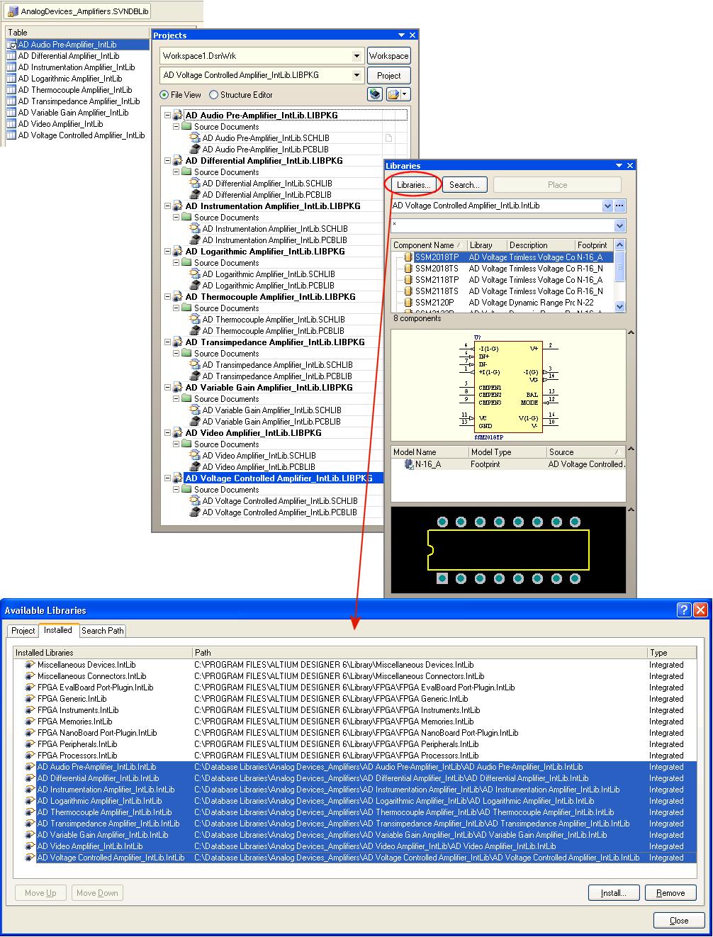
16 If the source library is a DBLib and PCB3D and/or Simulation model links have been defined in the database record, the referenced PCB3D library and Simulation model files are also added to the LIBPKG. The location of such models remains unchanged. The full path to a model is specified as part of its corresponding model link. The LIBPKG is then compiled to give the integrated library (e.g. AD Differential Amplifier_IntLib.IntLib), which is subsequently added to Altium Designer's Installed Libraries. Figure 13 shows an example of initial tables listed in a database library, the creation of source library package projects for each of those tables, and the resulting addition of the subsequently-compiled integrated libraries to the Installed Libraries list.
17

18 Figure 13. Resulting integrated libraries are added to the Installed Libraries. All documents - LIBPKG, SCHLIB, PCBLIB and INTLIB - are stored in a sub-folder in the output directory nominated in the Wizard. Once again, the table name is used to name this sub-folder. Figure 14. Storage of generated output - one sub-folder per database table. For more information on setting up and using a Database Library, refer to the Using Components Directly from Your Company Database document. For more information on using an SVN Database Library, refer to the Working with Version-Controlled Database Libraries document. Creating an SVNDBLib from Source Libraries (Sch/Pcb) You may have opted to use source schematic and PCB libraries - added to the design project - rather than compiling them into an integrated library. Maybe you wish to edit the source components in these libraries frequently, and prefer not to decompile and recompile the corresponding IntLib each time. Version-controlled database libraries offer a similar deal - the ability to quickly access the source libraries for modification, coupled with the security of having those libraries stored in a source control repository. Altium Designer facilitates the quick and simple conversion from your existing source schematic and PCB libraries, into the SVN Database Library structure. Conversion is performed with the SVN Database Library Conversion Wizard, in much the same way as when converting an integrated library. Multiple libraries of each type may be included in the conversion, with each schematic library added as a separate table to the target database. Choosing the Source Libraries The source libraries to be used in the conversion are specified on the initial page of the Wizard. As the Wizard pre-populates with library entries based on where it is accessed from, you can save time by launching the Wizard from the right place to begin with: From the Schematic Library Editor - with the source schematic library open, access to the Wizard can be made using the Tools» SVN Database Library Maker command. However, should you wish to involve the linked footprint models in the conversion, you will need to browse for, and add, the respective PCB footprint libraries. From the PCB Library Editor - with the source PCB library open, access to the Wizard can be made using

19 the Tools» SVN Database Library Maker command. However, conversion of the PCB footprint libraries alone is not a typical scenario and you will therefore need to browse for, and add, the respective schematic component libraries. From the Projects panel - this is by far the easiest method and requires that the source schematic and PCB libraries are added to a project. Quite often, this will be the case, when integrated libraries have not been used. Simply right-click on the entry for a library file and choose the SVN Database Library Maker command. The Wizard will automatically load all project libraries (Figure 15). Irrespective of how you access the Wizard you can of course modify the list of libraries to be converted, using the A dd and Remove buttons. The former gives access to the Library Files dialog, from where you can browse to and select schematic and PCB libraries to add to the list. Figure 15. Populating the list of libraries to be converted, automatically, with all source libraries in a project. Conversion Options Use the second page of the Wizard to define conversion-related options. These are options relating to how the source libraries should be split, in which directories of which repository they should be stored, and the output directory for the SVNDBLib file. For more information, see the section Specifying Conversion Options, earlier in this document. Proceeding with the Conversion After choosing the source libraries and setting the related conversion options as required, click Next to proceed with the conversion. A progress bar will be displayed, along with information on the current library being converted. The conversion process involves: Splitting the schematic and PCB libraries into single symbol/footprint library files

20 Committing the split symbol and footprint libraries to the repository, in the specified base directories. The Wizard will only extract footprint model reference information. Linked PCB3D and Simulation models are not supported for an SVNDBLib. Where such links exist, they will be added as parameters. Building a separate database table in the generated Access database, for each schematic library being converted, complete with parameter and model information extracted from the components therein. Each table is named using the name of the schematic library, with an _SchLib suffix (e.g. Mixer_SchLib). Creating the specified SVNDBLib file, connecting to the database and repository. After the conversion has completed, click Finish to make the SVNDBLib file active in the main design window. For more information on using your newly-created SVN Database Library, refer to the Working with Version-Controlled Database Libraries document. Converting a DBLib to an SVNDBLib You may already be enjoying the power of the Database Library feature - having perhaps converted your existing integrated libraries to the DBLib structure, or having created a DBLib from scratch. With the advent of version-controlled database libraries, you may want to move your source symbol and footprint libraries under the protective and secure wing of a source control repository. Altium Designer provides the means to effect this migration, from your current DBLib to an SVNDBLib. Access to the Wizard can be made from a number of places. You can of course browse for the DBLib you wish to convert, by clicking on the folder icon, to the far right of the Database Libraries field. With the original Database Library file (*.DBLib) open as the active document, run the *SVN Database Library Maker* command from the main Tools menu. The SVN Database Library Conversion Wizard will appear. The initial page of the Wizard will have the Database Libraries option already enabled, with the path to the source DBLib file already entered (Figure 16).
21 Figure 16. Selecting the Database Library (DBLib) to be converted. Conversion Options Use the second page of the Wizard to define conversion-related options. These are options relating to how the source schematic and PCB libraries should be split, in which directories of which repository they should be stored, and the output directory for the SVNDBLib file. For more information, see the section Specifying Conversion Options, earlier in this document. Note : As the external database already exists - linked to the original DBLib file - one will not be created. The database will remain in its current location. Should you wish to have the generated SVNDBLib file and the database in the same location, you basically have two options: Set the output path for the SVNDBLib to be the same directory in which the database currently resides. Generate the SVNDBLib in a different directory and then move the database to that directory. You will need to remember to modify the connection within the SVNDBLib file to point to the database in its new location and reconnect. Proceeding with the Conversion After choosing the source DBLib file and setting the related conversion options as required, click Next to proceed with the conversion. A progress bar will be displayed, along with information on the current library being converted. The conversion process involves: Splitting the schematic and PCB libraries, referenced by the component records in the linked database, into single symbol/footprint library files Committing the split symbol and footprint libraries to the repository, in the specified base directories. Creating the specified SVNDBLib file, connecting to the database and repository. After the conversion has completed, click Finish to make the SVNDBLib file active in the main design window. A Word about Field Mappings... In the generated SVNDBLib the mappings defined between fields in the database and design parameters, on the Fi eld Mappings tab, remain as they were originally defined in the DBLib. This is illustrated by example in Figure 17.

22 Figure 17. Field mappings remain the same between the original DBLib and the generated SVNDBLib. There are, however, two important areas to highlight: Any defined path mappings for symbols and footprint models are ignored. The SVNDBLib uses only the mapped reference fields ([Library Ref] and [Footprint Ref]) for locating the required symbol and footprint within the libraries committed to the repository. The path information defined in the database is ignored as it points to libraries located on a hard disk or other local/network medium. This path information can be modified, post conversion, to point to the libraries in the repository. For more information, see the next section - Modifying Database Path Information. Any defined PCB3D and Simulation model mappings will also remain defined in the SVNDBLib file. However, storage of PCB3D model libraries and simulation model files in the Subversion repository is not supported. Although the model links will be added to a component instance when placed, the models themselves will not be found.
![Modifying Database Path Information When you place a component from an SVN Database Library its symbol (specified by the [Library Ref] mapping) and footprint model (specified by the [Footprint Ref]](/docs-images/87/95556955/images/23-0.jpg "mapping) are extracted from symbol and model libraries in the version control repository. The base directories in which these symbols and models reside are specified as part of the conversion options.")
23 Modifying Database Path Information When you place a component from an SVN Database Library its symbol (specified by the [Library Ref] mapping) and footprint model (specified by the [Footprint Ref] mapping) are extracted from symbol and model libraries in the version control repository. The base directories in which these symbols and models reside are specified as part of the conversion options. Within the generated SVNDBLib file, these directories can be found on the SVN Repository tab of the Database Library Options dialog. Figure 18. Specifying base repository directories for symbols and footprints. In the example of Figure 18, the location for the schematic symbols and PCB footprint models have been set to point to the following sub-folders within the repository structure: The SYM folder for symbols The FTPT folder for footprints. It is important to stress that the symbols and footprints must reside within the base repository directories specified. They can of course be in sub-folders of those directories and the paths specified for both symbols and footprints can point to the same directory in the repository. The following methods can be used to locate the required symbol and footprint model within these nominated base directories: Absolute Path - the full path to the location of the library can be entered into the database. (e.g. vn/altium/svntest/schematicsymbols/capacitor_nonpolarized.schlib).
24 Relative Path - a relative path (relative to the root of the repository) to the location of the library can be entered into the database. The URL for the repository - specified on the SVN Repository tab of the Database Library Options dialog - will be prefixed to the path you enter, to give the absolute address. Considering Figure 18 for example, if you specify /SVNTest/SchematicSymbols/Capacitor_NonPolarized.SchLib, the full path will be Filename Only - you can simply specify the name of the library in which to find the required symbol or footprint, again within the database record for the component. The first file found with this name will be used. (e.g. Capacitor_NonPolarized.SchLib). When searching for a symbol/model match, the flattened folder paths in the base symbol or footprint directory are sorted and searched alphabetically. When the SVNDBLib has been generated from an existing DBLib, there will always be a corresponding library with the name of the actual symbol/footprint. No Path Information - you can opt not to enter any path information in the database record for the component. When locating the symbol/footprint, the system will initially look for the first library named like the symbol or footprint itself. For example, if the logical symbol name in the database (specified by the [Library Ref] mapping) is DIO-SCHOTTKY-2S, the system will look for the first file named DIO-SCHOTTKY-2S.SchLib and look for the symbol within this file. If the symbol/footprint cannot be found in this way, the system will look for a match in all libraries. Database field values can be modified directly from the Table Browser tab of the SVNDatabaseLib Editor. For more information, refer to the section Modifying a Database Table through the SVNDBLib File, in the Workin g with Version-Controlled Database Libraries document. After conversion from DBLib to SVNDBLib, path information will be ignored, as it points to the original libraries located on a hard disk for example. Should you wish to still include path information in the database, simply modify the information to point to the libraries in the repository - using any of the first three methods listed previously. It is worth remembering that not specifying library path information in the database makes it much more robust. The repository location and/or its internal folder structure could be changed and the database would not need to be updated. For more information on using your newly-created SVN Database Library, refer to the Working with Version-Controlled Database Libraries document. Direct OrCAD CIS Support Built on the foundation of the database library system, Altium Designer provides full support for connection to, and use of, existing OrCAD Component Information Systems (CIS). The CIS structure is essentially converted into Altium Designer's Database Library structure. From OrCAD to Altium Designer - Translations Required To provide the facility for direct placement from the external database (*.mdb, *.xls), the following file translations are required: The OrCAD CIS Configuration File (*.dbc), which handles the link to the external database and includes the
? Schematic Library (*.SchLib) OrCAD Max Library File (*.LLB)? PCB Library (*.")
25 database field-to-design parameter mapping information, must be translated into an Altium Designer Database Library file (*.DBLib). The relevant OrCAD library files must be translated into Altium Designer library files: OrCAD Capture Library (*.OLB)? Schematic Library (*.SchLib) OrCAD Max Library File (*.LLB)? PCB Library (*.PcbLib). Creating the Database Library Automatically The simplest and most efficient method to create the DBLib file and source Altium Designer libraries, is to use the Im port Wizard ( File» Import Wizard ). On the second page of the Wizard, ensure that the OrCAD CIS Configuration Files and Libraries entry is selected as the import file type (Figure 19). Figure 19. Use the Import Wizard to quickly create the DBLib and source library files. Follow the subsequent pages of the Wizard, in which you are required to specify: The location of the external database The location of the CIS Configuration File The location of the target DBLib file. The OrCAD Schematic and/or PCB libraries referenced by the external database. When specifying the location of the target DBLib file, either specify the path and name for a new file to be created, or browse to and open an existing file. When specifying the OrCAD source libraries, you also have control over where the resulting Altium Designer

26 libraries are saved. By default, these libraries will be saved to the sub-folder Libraries, located in the same directory as the target DBLib file. Figure 20 illustrates completed Wizard entries for an example OrCAD database - BENCH.mdb. Figure 20. Specify the OrCAD database, CIS Config file and source libraries and the target DBLib file. Proceeding with the Import After specifying the source and target files and directories as required, click Next to proceed with the import. After the import is completed, click Finish to make the specified Database Library file active in the main design window (Figure 21).

27 Figure 21. Resulting DBLib document after the OrCAD files have been translated. A library search path is automatically added to the DBLib file, which points to the directory containing the translated library files. The parameter mapping information - including the defined lookup key - is taken directly from the OrCAD CIS file. In addition, you will notice from Figure 21 that the following two model mapping entries are automatically set: Layout PCB Footprint? [Orcad Footprint] Schematic Part? [Orcad Library] These entries provide the link to the source schematic symbol for a particular component record in the external database, and the applicable PCB Footprint model linked to that component. Determine mapped parameter update options as required.
. Setup the connection to the Orcad external database.")
28 Creating the Database Library Manually Creation of the DBLib file using the Import Wizard is the fastest method, but not the only method. You can of course create the DBLib file manually. First, you will need to create and define the DBLib file: Create a new Database Library document ( File» New» Library» Database Library). Setup the connection to the Orcad external database. Once connected, ensure that the field mappings are as required, especially the schematic symbol and footprint model mappings. Define mapped parameter update options as required. For more information on setting up the DBLib file, refer to the Using Components Directly from Your Company Database application note. You will then need to import the OrCAD libraries. This can be achieved by using the Import Wizard ( File» Import Wizard ) to translate the OrCAD library files (*.OLB, *.LLB) into Altium Designer libraries (*.SchLib, *.PcbLib). When choosing the file types to import, select the OrCAD Designs and Libraries Files entry. Skip the page for Import ing OrCAD Designs and proceed to the page for Importing OrCAD Libraries (Figure 22). Add all source OrCAD libraries referenced by the database. Figure 22. Specify the OrCAD libraries to be translated. On the Output Libraries page of the Wizard (Figure 23), specify the output directory for the generated library files. After the import is complete, a folder - Imported OrCAD Libraries.PrjPcb - will be generated in the nominated directory.


29 Figure 23. Specify an output folder for the generated Altium Designer libraries. You can simply move the generated Altium Designer libraries contained within to another location and delete this folder. For example, you may want to move the libraries to a folder named Libraries - created within the directory containing the DBLib file. Once you have the symbol and footprint libraries, you will need to go back to the DBLib file and set up the library search paths to point to the directory folder in which those libraries are stored. Figure 24. Add a search path to the DBLib file, targeting the generated source libraries.
30 Placement and Maintenance Once the DBLib file is created, the mapping defined as required and the source libraries translated and targeted with a suitable DBLib search path, you can add the library to the Available Libraries list. Once added, you can place a component onto the schematic, with the parameter and footprint model information added on-the-fly, directly from the database. For further information, refer to the section Countdown to Placement, in the Using Components Directly from Your Company Database application note. After placement, the chosen key parameter in the DBLib file is used to ensure that the placed component on the schematic retains its link to the corresponding record for that component in the external database. This means that at any stage in the future, changes to parameter and model information in the database can be easily passed back to the placed component, synchronizing the two. In the PCB Editor, use the Tools» Update From PCB Libraries command to update placed footprints with the latest information stored in the source libraries. If you simply want to update parameter information, use the Update Parameters From Database command, available from the Schematic Editor's main Tools menu. To perform a full update, including parameters, model and graphical attributes of schematic symbols, use the Updat e From Libraries command (also available from the Schematic Editor's main Tools menu). For further information, refer to the Keeping Components Up-To-Date document.
Creating a Database Library from an Integrated Library
 Published on Online Documentation for Altium Products (https://www.altium.com/documentation) Home > Database Library Migration Tools Using Altium Documentation Modified by Jason Howie on Apr 11, 2017 Parent
This document provides detailed information on placing components from a database using Altium Designer's SVN Database Library feature.
 Old Content - visit altium.com/documentation Mod ifi ed by on 13- Sep -20 17 This document provides detailed information on placing components from a database using Altium Designer's SVN Database Library
Working with Version-Controlled Database Libraries. Contents
 Working with Version-Controlled Database Libraries Contents Librarian or Designer? Working as a Librarian The Source Control Repository Using the Library Splitter Wizard Creating the SVN Database Library
Using the SVN Database Library Conversion Wizard
 Published on Online Documentation for Altium Products (https://www.altium.com/documentation) 主页 > SVN Database Library Conversion Wizard Using Altium Documentation Modified by Rob Evans on Jun 19, 2017
Building an Integrated Library
 Building an Integrated Library Old Content - visit altium.com/documentation Modified by on 6-Nov-2013 Integrated libraries combine schematic libraries with their related PCB footprints and/or SPICE and
USING THE Integrated Library to Database Library Translator WIZARD
 Published on Online Documentation for Altium Products (http://www.altium.com/documentation) Home > Integrated Library To Database Library Translator Wizard A New Era for Documentation Modified by Phil
Using Components Directly from Your Company Database
 Using Components Directly from Your Company Database Old Content - visit altium.com/documentation Modified by Phil Loughhead on 18-May-2016 This document provides detailed information on using components
Component, Model and Library Concepts
 Component, Model and Library Concepts Old Content - visit altium.com/documentation Modified by Susan Riege on 6-Aug-2016 Related Resources Net Ties and How to Use Them (PDF) This article explains Altium
Published on Online Documentation for Altium Products (
 Published on Online Documentation for Altium Products (https://www.altium.com/documentation) Home > Storage Manager Using Altium Documentation Modified by Jason Howie on Jun 16, 2017 Parent page: System
Storage Manager. Summary. Panel access. Modified by on 10-Jan-2014
 Storage Manager Old Content - visit altium.com/documentation Modified by on 10-Jan-2014 Related panel: Differences Panel Related documents: Version Control and Altium Designer Version Control Terminology
Published on Online Documentation for Altium Products (
 Published on Online Documentation for Altium Products (https://www.altium.com/documentation) Home > Managed Schematic Symbols Using Altium Documentation Modified by Jason Howie on Jun 22, 2018 Parent page:
Generating a Custom Bill of Materials
 Generating a Custom Bill of Materials Old Content - visit altium.com/documentation Modified by on 6-Nov-2013 This tutorial describes how to use the Report Manager to set up a Bill of Materials (BOM) report.
Moving to Altium Designer From OrCAD. Contents
 Moving to Altium Designer From OrCAD Contents File Translation OrCAD Capture 10.x *.DSN Files and the Unrecognized Project File Version Error Default Layer Mapping for PCB Using the Import Wizard for OrCAD
By defining design repositories in this centralized fashion, an oganization can fully control which repositories its designers can access and use.
 Local Version Control Service Old Content - see latest equivalent Modified by Jason Howie on 31-May-2017 Parent article: Altium Vault The Altium Vault installation provides localized (and centralized)
Folder Type. Parent page: Managed Domain Models
 Published on Online Documentation for Altium Products (https://www.altium.com/documentation) 主页 > Managed Simulation Models Using Altium Documentation Modified by Jason Howie on Jun 22, 2018 Parent page:
Support for 3D Models. Folder Type. Modified by Jason Howie on May 31, 2017
 Support for 3D Models Old Content - see latest equivalent Modified by Jason Howie on May 31, 2017 The Altium Vault 2.5 release, in conjunction with Altium Designer 15.1, brings support for vault-based
NEW USER S GUIDE TO DEFINING A LIBRARY METHODOLOGY
 When choosing a PCB library methodology, there is no one universal solution for all users. While some small business users may require only a bare essential yet the extremely flexible representation of
Moving to Altium Designer from PADS Layout and OrCAD capture. Contents
 Moving to Altium Designer from PADS Layout and OrCAD capture Contents Getting Started - Transferring Your PADS Layout Designs Using the Import Wizard for PADS Layout Files Layer Mapping for PADS PCB ASCII
Using the Import Wizard
 Published on Online Documentation for Altium Products (https://www.altium.com/documentation) 主页 > Import Wizard Using Altium Documentation Modified by Phil Loughhead on Jun 18, 2017 The Import Wizard will
Component Management in SOLIDWORKS PCB
 Component Management in SOLIDWORKS PCB Modified by Jason Howie on Oct 24, 2017 Parent page: Exploring SOLIDWORKS PCB A component is the general name given to a part that can be placed into an electronic
Published on Online Documentation for Altium Products (http://www.altium.com/documentation)
") Published on Online Documentation for Altium Products (http://www.altium.com/documentation) Home > Managed Projects Usability Improvements A New Era for Documentation Modified by Rob Evans on Apr 11, 2017
Published on Online Documentation for Altium Products (http://www.altium.com/documentation) Home > Managed Projects Usability Improvements A New Era for Documentation Modified by Rob Evans on Apr 11, 2017
Parent page: PCB Panel
 Published on Online Documentation for Altium Products (https://www.altium.com/documentation) 主页 > PCB Library Using Altium Documentation Modified by Annika Krilov on Apr 11, 2017 Parent page: PCB Panel
Securing Design Source Inside a Design Repository
 Securing Design Source Inside a Design Repository Old Content - see latest equivalent Modified by Jason Howie on 31-May-2017 Parent article: Board Design Release The best way of working from a known set
Published on Online Documentation for Altium Products (
 Published on Online Documentation for Altium Products (https://www.altium.com/documentation) Home > Managed Simulation Models Using Altium Documentation Modified by Jason Howie on Jun 22, 2018 Parent page:
Moving to Altium Designer From P-CAD. Contents
 Moving to Altium Designer From P-CAD Contents File Translation Translation Overview Using the Import Wizard for P-CAD Files Working with Documents The Schematic Symbol Is the Component... P-CAD Components
Moving to Altium Designer from Protel 99 SE. Contents
 Moving to Altium Designer from Protel 99 SE Contents Design Database Become a Design Workspace & Projects Importing a 99 SE Design Database Creating the Altium Designer Project(s) Manually Adding and Removing
Libraries. Modified by Jason Howie on Oct 24, Parent page: IntegratedLibrary Panels
 Libraries Modified by Jason Howie on Oct 24, 2017 Parent page: IntegratedLibrary Panels Use the Libraries panel to access components in libraries currently available in SOLIDWORKS PCB. Summary The Libraries
ActiveBOM - BOM Catalog
 ActiveBOM - BOM Catalog Old Content - visit altium.com/documentation Modified by Admin on Nov 29, 2016 Parent article: ActiveBOM The BOM Catalog tab is a constituent part of the BOM document (*.BomDoc),
Published on Online Documentation for Altium Products (
 Published on Online Documentation for Altium Products (https://www.altium.com/documentation) Главная > Working with the Explorer Panel - Feature How-Tos Using Altium Documentation Modified by Jason Howie
Importing the Source Models. Placing a 3D Model in the Workspace. Modified by on 25-Jul-2014
 Importing the Source Models Old Content - visit altium.com/documentation Modified by on 25-Jul-2014 Placing a 3D Model in the Workspace A 3D model can be placed into a PCB document at any time. Note that
Function. Description
 Function Check In Get / Checkout Description Checking in a file uploads the file from the user s hard drive into the vault and creates a new file version with any changes to the file that have been saved.
Lesson 12: Preparing for Post Processing
 12 Lesson 12: Preparing for Post Processing Learning Objectives In this lesson you will: Rename reference designators on the board design Backannotate changes made in the OrCAD and Allegro PCB Editor to
Releasing a PCB 2D-3D Model to a Vault
 Releasing a PCB 2D-3D Model to a Vault Old Content - see latest equivalent Modified by Jason Howie on 31-May-2017 Parent article: Vault-Based Domain Models From a designer's perspective, a vault-based
Understanding Design Annotation. Contents
 Understanding Design Annotation Contents Annotation defined Annotation in Altium Designer Which Annotation Tool? Schematic Level Annotation Order of Processing Schematic Sheets to Annotate Annotation Scope
Published on Online Documentation for Altium Products (https://www.altium.com/documentation)
") Published on Online Documentation for Altium Products (https://www.altium.com/documentation) Главная > Local Version Control Service Using Altium Documentation Modified by Jason Howie on May 8, 2018 Parent
Published on Online Documentation for Altium Products (https://www.altium.com/documentation) Главная > Local Version Control Service Using Altium Documentation Modified by Jason Howie on May 8, 2018 Parent
Moving to Altium Designer from Pads Logic and PADS Layout
 Moving to Altium Designer from Pads Logic and PADS Layout Old Content - visit altium.com/documentation Modified by on 13-Sep-2017 Translating complete PADS Logic and PADS Layout designs, including PCB,
Published on Online Documentation for Altium Products (
 Published on Online Documentation for Altium Products (https://www.altium.com/documentation) Home > Understanding Models, Components and Libraries Using Altium Documentation Modified by Phil Loughhead on
If you are new to version control systems and are wondering where to start, read the article Version Control and Altium Designer.
 Tutorial - Using Version Control in Altium Designer Old Content - visit altium.com/documentation Modified by on 6-Nov-2013 Altium Designer supports Subversion (SVN) and Concurrent Versions System (CVS).
Published on Online Documentation for Altium Products (
 Published on Online Documentation for Altium Products (https://www.altium.com/documentation) Home > Using Version Control Using Altium Documentation Modified by Rob Evans on Apr 11, 2017 RELATED INFORMATION
A Walk Through...the Board Design Release Process. Contents
 A Walk Through...the Board Design Release Process Contents Design Project - Initial Preparation Create a New Design Repository Add Your Project to the Design Repository Connect to an Altium Vault Define
Copy of A Walk Through...the Board Design Release Process
 Copy of A Walk Through...the Board Design Release Process Language Japanese Contents Design Project - Initial Preparation Create a New Design Repository Add Your Project to the Design Repository Connect
Managed Projects. Modified by Jason Howie on 31-May-2017
 Managed Projects Old Content - see latest equivalent Modified by Jason Howie on 31-May-2017 Altium Designer 14.3, in conjunction with the latest Altium Vault, brings support for Managed Projects. In the
Moving to Altium Designer from Protel 99 SE
 Moving to Altium Designer from Protel 99 SE Summary This article outlines the process you go through to transfer a Protel 99 SE design into the Altium Designer environment. Protel 99 SE uses the design
Linking a Simulation Model to a Schematic Component
 Linking a Simulation Model to a Schematic Component Old Content - visit altium.com/documentation Modified by on 13-Sep-2017 Altium Designer provides a powerful mixed-signal circuit simulator, enabling
Altium I (Circuit Design & Simulation)
") Altium I (Circuit Design & Simulation) ELEC391 PCB Design support for ELEC391: Altium 2014, 150 licenses Lecture talks: Jan 22 Altium I (Circuit Design + Simulation) Feb 1 Altium II (PCB Layout) TBA Guest
Altium I (Circuit Design & Simulation) ELEC391 PCB Design support for ELEC391: Altium 2014, 150 licenses Lecture talks: Jan 22 Altium I (Circuit Design + Simulation) Feb 1 Altium II (PCB Layout) TBA Guest
Next Generation Component Management
 Next Generation Component Management Summary This document provides a conceptual walkthrough of Altium's nextgeneration component management model. The traditional model of a design component faithfully
CadSoft EAGLE Importer
 CadSoft EAGLE Importer Old Content - visit altium.com/documentation Modified by on 31-Jan-2014 Related Videos EAGLE Importer Not all design work is done in Altium Designer. If you are new to Altium Designer,
Published on Online Documentation for Altium Products (
 Published on Online Documentation for Altium Products (https://www.altium.com/documentation) Главная > Working with the Vaults Panel - Feature How-Tos Using Altium Documentation Modified by Jason Howie
Linking a Simulation Model to a Schematic Component. Contents
 Linking a Simulation Model to a Schematic Component Contents Model Conversion Creating the Schematic Component Adding the Link Configuring the Link Specifying Model Type Linking to a SPICE 3f5 Model The
Multi-Channel Design Concepts
 Multi-Channel Design Concepts Old Content - visit altium.com/documentation Modified by on 6-Nov-2013 Altium Designer introduces a robust multi-channel design system that even supports channels nested within
USER GUIDE. MADCAP FLARE 2017 r3. Source Control: Git
 USER GUIDE MADCAP FLARE 2017 r3 Source Control: Git Copyright 2018 MadCap Software. All rights reserved. Information in this document is subject to change without notice. The software described in this
Published on Online Documentation for Altium Products (
 Published on Online Documentation for Altium Products (https://www.altium.com/documentation) Home > NEXUS - FAQs Using Altium Documentation Modified by Jason Howie on Jun 16, 2018 Parent page: Introducing
Welcome to the Altium Designer Environment
 Welcome to the Altium Designer Environment Summary Guide GU0112 (v1.0) April 29, 2005 Altium Designer brings a complete electronic product development environment to your PC s Desktop, providing multi-document
How to create a PDF document for Duplicating to print for you.
 How to create a PDF document for Duplicating to print for you. Quick Instructions: 1. Make sure you have access to a printer with a postscript driver. 2. Map a drive letter to the PDF creation share on
Server Installation. Parent page: System Installation, Licensing & Management
 Published on Online Documentation for Altium Products (https://www.altium.com/documentation) ホーム > Altium Infrastructure Server 製品マニュアル Modified by Rob Evans on Feb 20, 2018 Parent page: System Installation,
Published on Online Documentation for Altium Products (https://www.altium.com/documentation)
") Published on Online Documentation for Altium Products (https://www.altium.com/documentation) Home > Altium DXP Developer Using Altium Documentation Modified by Rob Evans on May 16, 2018 Reference information
Published on Online Documentation for Altium Products (https://www.altium.com/documentation) Home > Altium DXP Developer Using Altium Documentation Modified by Rob Evans on May 16, 2018 Reference information
Source Control: Subversion
 USER GUIDE MADCAP FLARE 2018 Source Control: Subversion Copyright 2018 MadCap Software. All rights reserved. Information in this document is subject to change without notice. The software described in
Enterprise Architect. User Guide Series. Time Aware Models. Author: Sparx Systems. Date: 30/06/2017. Version: 1.0 CREATED WITH
 Enterprise Architect User Guide Series Time Aware Models Author: Sparx Systems Date: 30/06/2017 Version: 1.0 CREATED WITH Table of Contents Time Aware Models 3 Clone Structure as New Version 5 Clone Diagram
Figure 1. Output jobs are configured as an OutJob file, giving you full control over print-based output.
 PCB Printout Output Options Old Content - visit altium.com/documentation Modified by Admin on Sep 13, 2017 Print-based Output Print-based output for your PCB project in Altium Designer is available through
Connectivity and Multi-Sheet Design. Contents
 Connectivity and Multi-Sheet Design Contents Defining Sheet Structure Building a Hierarchical Structure Top-Down Design Bottom-Up Design Mixed Schematic/HDL Document Hierarchy Maintaining Hierarchy Synchronizing
National Fire Incident Reporting System (NFIRS 5.0) Configuration Tool User's Guide
 Configuration Tool User's Guide") National Fire Incident Reporting System (NFIRS 5.0) Configuration Tool User's Guide NFIRS 5.0 Software Version 5.3 Prepared for: FEMA Round Hill, VA 20142 Prepared by: Verizon Federal Incorporated P.O.
National Fire Incident Reporting System (NFIRS 5.0) Configuration Tool User's Guide NFIRS 5.0 Software Version 5.3 Prepared for: FEMA Round Hill, VA 20142 Prepared by: Verizon Federal Incorporated P.O.
Attaching a Datasheet to a Component Item in the Vaults Panel
 Published on Online Documentation for Altium Products (https://www.altium.com/documentation) Home > Storing Component Datasheets in an Altium Vault Using Altium Documentation Modified by Jason Howie on
PCB Release View. Contents
 PCB Release View Contents View Breakdown Open Projects Project Configurations Process Flow File Generation Using the View in Design Mode Getting Access to Release Mode Validation and Output Generation
Extensions Management Interface. Parent page: System Installation, Licensing & Management
 Published on Online Documentation for Altium Products (https://www.altium.com/documentation) 主页 > 扩展Altium Designer Using Altium Documentation Modified by Jun Chu on Jan 29, 2018 Parent page: System Installation,
GiftMaker Pro & EventMaker Pro 8.2
 GiftMaker Pro & EventMaker Pro 8.2 Update Installation Instructions Windows Please be sure you have a working backup copy of your data file before proceeding. To install any of the Pro Series version 8.2
Moving to Altium Designer From P-CAD
 Summary Application Note AP0130 (v3.0) September 10, 2008 This application note highlights the key differences you need to be aware of when moving from P-CAD to Altium Designer. It will help you ramp up
User Manual. DocKIT for SharePoint
 User Manual DocKIT for SharePoint-2003 ------------------------------------------------------------------ Table of Contents 1 DocKIT Introduction 1 1.1 About DocKIT 1 1.2 DocKIT Primer 2 1.3 Who can Use
Accessing the Vault. Parent article: Altium Vault Technology. Mod. ifi. Adm. Sep 13,
 Frozen Content Mod ifi ed by Adm in on Sep 13, 201 7 Parent article: Altium Vault Technology This page contains information regarding browser-based access to the legacy Altium Vault Server. For browser-based
A Walk Through the Board Design Release Process
 A Walk Through the Board Design Release Process Frozen Content Modified by Jason Howie on 31-May-2017 Parent article: Board Design Release Altium's Design Data Management system includes a range of technologies
BLUEPRINT TEAM REPOSITORY. For Requirements Center & Requirements Center Test Definition
 BLUEPRINT TEAM REPOSITORY Installation Guide for Windows For Requirements Center & Requirements Center Test Definition Table Of Contents Contents Table of Contents Getting Started... 3 About the Blueprint
REO SERIES RA2000. Application Note for Creating a Disk-to-Disk (D2D) Backup Strategy Utilizing the RA2000 with VERITAS Backup Exec 8.
 Backup Strategy Utilizing the RA2000 with VERITAS Backup Exec 8.") Overland Storage REO SERIES RA2000 Application Note for Creating a Disk-to-Disk (D2D) Backup Strategy Utilizing the RA2000 with VERITAS Backup Exec 8.6 Overland Storage REO SERIES RA2000 Creating a D2D
Overland Storage REO SERIES RA2000 Application Note for Creating a Disk-to-Disk (D2D) Backup Strategy Utilizing the RA2000 with VERITAS Backup Exec 8.6 Overland Storage REO SERIES RA2000 Creating a D2D
EQuIS Data Processor (EDP) User Manual
 User Manual") EQuIS Data Processor (EDP) User Manual Introduction EQuIS Data Processor (EDP) Introduction The EQuIS Data Processor, or EDP, is today s answer to the many data quality issues that plague data managers.
EQuIS Data Processor (EDP) User Manual Introduction EQuIS Data Processor (EDP) Introduction The EQuIS Data Processor, or EDP, is today s answer to the many data quality issues that plague data managers.
Lesson 19: Processing a Hierarchical Design
 Lesson 19: Processing a Hierarchical Design Lesson Objectives After you complete this lesson you will be able to: Annotate a hierarchical design Perform a Design Rule Check on a hierarchical design Correct
Licensing System - FAQs Further Information License types License availability, selection and configuration Using an On-Demand License On-Demand mode
 Licensing System - FAQs Further Information License types License availability, selection and configuration Using an On-Demand License On-Demand mode Roaming mode Working offline Releasing a license remotely
5 WAYS TO CUSTOMIZE ALTIUM DESIGNER FOR BETTER EFFICIENCY
 Menu items, shortcut keys, and toolbar icons are the three ways of accessing features within the Altium Designer environment. All of these are customizable and may enhance the user experience with Altium
K2 ServerSave Installation and User Guide
 K2 ServerSave Installation and User Guide Chapter 1: Introduction 1.1 What is K2 ServerSave? Welcome to the K2 ServerSave Server Edition User Guide. This guide briefly describes the K2 ServerSave Application
Unified CVP Migration
 If there is a change in platform of a later release of Unified CVP, migration from the existing release to the later release is required. For example, moving from Unified CVP 8.5(1) to Unified CVP 10.0(1)
Upgrading from Call Center Reporting to Reporting for Call Center
 Upgrading from Call Center Reporting to Reporting for Call Center www.nortelnetworks.com 2003 Nortel Networks i Table of Contents Table of Contents Change History...1 How to use this guide...2 Introduction...
to be handled, tracked and verified, otherwise the components' designators and other design data can become out of sync.
 Understanding Design Annotation Old Content - visit altium.com/documentation Modified by Admin on Nov 6, 2013 This document explores the process of annotation in Altium Designer - from understanding Schematic,
Releasing a Simulation Model to a Vault
 Releasing a Simulation Model to a Vault Old Content - see latest equivalent Modified by Jason Howie on May 31, 2017 Parent article: Vault-Based Domain Models From a designer's perspective, a vault-based
Summary. Access. The dialog is accessed from the PCB Editor, by selecting Design» Rules from the toolbar.
 Published on Online Documentation for Altium Products (http://www.altium.com/documentation) 主页 > PCB Rules and Constraints Editor Altium 技术文档新纪元 Modified by Phil Loughhead on Jun 19, 2017 The PCB Rules
Reliability and Performance Monitoring
 Reliability and Performance Monitoring June 19, 2012 Copyright 2012 by World Class CAD, LLC. All Rights Reserved. Reliability and Performance Monitor Window To open the Reliability and Performance Monitor
Migration to Unified CVP 9.0(1)
") The Unified CVP 9.0(1) requires Windows 2008 R2 server. The Unified CVP versions prior to 9.0(1) run on Windows 2003 server which do not support the upgrade to Unified CVP 9.0(1). Unified CVP supports
The Unified CVP 9.0(1) requires Windows 2008 R2 server. The Unified CVP versions prior to 9.0(1) run on Windows 2003 server which do not support the upgrade to Unified CVP 9.0(1). Unified CVP supports
AccuBridge for IntelliJ IDEA. User s Guide. Version March 2011
 AccuBridge for IntelliJ IDEA User s Guide Version 2011.1 March 2011 Revised 25-March-2011 Copyright AccuRev, Inc. 1995 2011 ALL RIGHTS RESERVED This product incorporates technology that may be covered
Published on Online Documentation for Altium Products (
 Published on Online Documentation for Altium Products (https://www.altium.com/documentation) Home > Configuring PCB Printouts Using Altium Documentation Modified by Jason Howie on Apr 20, 2017 Print-based
INSTALLATION GUIDE FOR LEWAPLUS PORTABLE
 Installation Guide for LewaPlus Portable Page 1 of 8 INSTALLATION GUIDE FOR LEWAPLUS PORTABLE This document will guide you step by step through the installation of the LewaPlus Portable application. FIRST
Editing Multiple Objects. Contents
 Editing Multiple Objects Contents Selecting Multiple Objects Inspecting the Objects Editing the Objects Editing Group Objects Step 1. Selecting the Capacitors Step 2. Changing the Comment String Step 3.
Source Control: Perforce
 USER GUIDE MADCAP FLARE 2018 Source Control: Perforce Copyright 2018 MadCap Software. All rights reserved. Information in this document is subject to change without notice. The software described in this
Nine Dot Connects PCB-Centric Training Courses & Schedule
 What s stopping you from designing hardware? In the world of PCB design, more than cursory knowledge of the PCB process and circuit theory is required. There are dozens of processes, hundreds of tasks,
Imagine. Create. Discover. User Manual. TopLine Results Corporation
 Imagine. Create. Discover. User Manual TopLine Results Corporation 2008-2009 Created: Tuesday, March 17, 2009 Table of Contents 1 Welcome 1 Features 2 2 Installation 4 System Requirements 5 Obtaining Installation
Version 11. NOVASTOR CORPORATION NovaBACKUP
 NOVASTOR CORPORATION NovaBACKUP Version 11 2009 NovaStor, all rights reserved. All trademarks are the property of their respective owners. Features and specifications are subject to change without notice.
SAM Data Management Manual
 SAM Data Management Manual For use with Student Achievement Manager version 2.6 and later Table of Contents Data Management Overview... 3 Roster Import... 4 Overview... 4 Automatic Account Creation During
E-ROW HELP V3.1. Creating a Race. Modify Race Dialog Box. Preferences Dialog Box
 Creating a Race e-row allows you to hold races among several Ergometers. These must be equipped with the PM2+ performance monitor. See the owner s manual for connecting the Ergometers for racing. To create
Express Migration Tool Guide
 Sitecore XP 8.2 Express Migration Tool Guide Rev: August 26, 2016 Express Migration Tool Guide Sitecore XP 8.2 How to upgrade from Sitecore 7.2 directly to Sitecore 8.2 Sitecore XP 8.2 Table of Contents
Releasing a Component Definition to a Vault
 Releasing a Component Definition to a Vault Old Content - see latest equivalent Mod ifi ed by Jas on How ie on 31May -20 17 Parent article: Vault-Based Components Once all prerequisite domain models have
Very Important: Conversion Pre-Planning Creating Your Single User Database Converting from Version 1.x, 2.x, or 3.x...
 INTRODUCTION... 2 INSTALLATION PRE-PLANNING... 2 Very Important:... 2 Conversion Pre-Planning... 2 INSTALLATION STAGE... 3 CONFIGURATION STAGE... 3 Creating Your Single User Database... 4 Opening an Existing
3. IMPORTANT: When prompted, accept the default Installation directory.
 Installing ProView 4.0.1 on your PC 1. Insert the ProView 4.0.1 CD-ROM into your CD-ROM Drive. The Install Shield Wizard should run automatically. If it does not, click Start then Run. Enter D:\setup.exe
Aras Innovator 11. Backup and Recovery Procedures
 Document #: 11.0.02015040601 Last Modified: 1/4/2018 Copyright Information Copyright 2018 Aras Corporation. All Rights Reserved. Aras Corporation 300 Brickstone Square Suite 700 Andover, MA 01810 Phone:
CADS Detailing FAQ s ENGINEERING SOFTWARE 004 Network Licence File - Installation Guide. 004 Network Licence File Installation Guide
 CADS Detailing FAQ s ENGINEERING SOFTWARE 004 Network Licence File - Installation Guide 004 Network Licence File Installation Guide The CADS Network licence does not use an active process to manage the
Working with EGL and Subversion Using RDi with RBD
 HISTORY OF MODIFICATIONS...2 CREATING A NEW REPOSITORY...3 BACKGROUND: INSTALLING TORTOISE...3 SUBVERSION EGL SOURCE CODE REPOSITORY...3 INSTALLING SUBVERSION PLUG-IN AND CONFIGURING FOR USE....5 INSTALLATION