BrickElectric Ethernet Relay
|
|
|
- Duane Wilkinson
- 6 years ago
- Views:
Transcription


1 BrickElectric Ethernet Relay BEM106 Excellent network building block Features WEB control / Port Forwarding Software update via Internet Auto ping and programmable reboot Hardware Reset 5-24 VDC power supply EasyBus - simple solution Android App LAN mode DHCP - Plug and play Internet Control Password Protection Introduction BEM106 is an Wide Supply Input, Ethernet Remote Relay Module, with 8 output channels, and provide with both enclosed and open type housing. Its Ethernet connector provides 10/100baseT interface. It supports EasyBus-TCP, HTTP control and Internet control protocols, suitable for being used with servers, computers, mobiles, routers, etc., to provide remote control and monitor. You can also define the port number for HTTP by yourself, to realize Router Port Forwarding. With DHCP functions, it doesn't need to make any settings anymore in field. So just plug and play, power it on and then enjoy your remote control. BEM106 is a new generation product with more functions and higher stability. Control mode "toggle" and "automatic cycle operation" are provided additionally.
2 Table of Contents 1. Device Overview General Ratings Connection Diagram Specifications Recommended Operating Conditions Default Software Settings Easy Start HTTP Mode LAN Mode Internet Mode: Functionality Basic Network Communications Save Parameters Reboot DHCP Function Static IP Address Relay outputs control Password protection Http port setting Hardware reset button Identification & customized information Auto ping and reboot mode Fast Program Reference Easybus Specifications Support & Contact us... 40
3 1. Device Overview 1.1 General Ratings Power Consumption 5W max. Operation Temperature -30 to +85 Module Size 150mmx80mmx20mm Weight Connection Diagram Fig. 1.1
4 2. Specifications 2.1 Recommended Operating Conditions Parameters At T = 25, V supply = 5V unless otherwise specified. Symbol Values Unit Min. Typ. Max. Operating voltage V s 5-24 V Output Relay Rating - 250VAC/10A - 125VAC/10A 24VDC/10A 12VDC/10A 2.2 Default Software Settings Default Settings IP Setting: IP address: Subnet Mask: Gateway: DHCP: disable HTTP function State: Enable Port: 80 Latest Firmware Version V You can download latest firmware for free. Internet Control State: Enable Platform with App: Android / ios (in prepare) / Windows (in prepare) Cross-Platform (Web Browser) in prepare

5 3. Easy Start A Practical step-by-step operation guide for starters This part is a step-by-step tutorial explaining how to start with BEM106. We'll not discuss too much details here. The only idea here is to make it work by minimum steps. For more information, please refer to later chapters. 3.1 HTTP Mode 1. Connect BEM106 with your routers or computer via a standard Ethernet cable. And then power it on with 5-24VDC power supply. (see fig.1.1 at page 2) 2. Open any Browser, for example Chrome is used here as demonstration. Please enter URL: Relay channel 1 will be toggled, and a message will be returned to your browser. Congratulations!
. Open it and see the following Fig.1.2: Fig.1.2 3.")
6 3.2 LAN Mode 1. Connect BEM106 with your routers or computer by Ethernet cable, and then power it on with 5-24VDC power supply. (see fig.1.1 at page 2) 2. Open any TCP test tool (if you don't have any, or you don't know what a TCP test tool is, you can use BE-Manager, it is within our software package). Open it and see the following Fig.1.2: Fig Click "Connect" button, and wait for module connected. Then, it is able control the relay module. Click "CH1 OFF" button, and the relay channel 1 will be switched on. See Fig.1.3
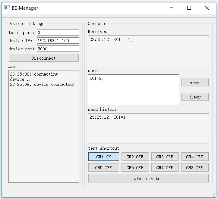
7 Fig.1.3
 2.")


8 3.3 Internet Mode: 1. Connect BEM106 with your routers or computer by Ethernet cable. And then power it on with 5-24VDC power supply. (see fig.1.1 at page 2) 2. Open "Hello Brick" app for android at any android phone, register a user and then have fun with Internet control. No other need at relay module is necessary. 3. If you need online help or need to contact us for customized functions, please click the bottom right red "online help button". One of our daily on duty R&D engineer will talk to you directly.
9 4. Functionality 4.1 Basic Network Communications The main method of communication to BEM106 is a standard Ethernet communication. This communication protocol makes use of Network Sockets or HTTP protocol to create point to point tunnels that data can flow through bi-directionally. In this way, the computer that is controlling the relay can send commands and shortly thereafter receive the response through the same Socket/Web Page. Communications In most programming languages, all you need to do to open a socket is to import the appropriate plug-in, build the socket object, and connect the socket using the IP Address and Port Number of the target device. MAC Address You can find the MAC Address of the module at the simple starter manual delivered together with module package. 4.2 Save Parameters After power cycle, BEM106 will lose its parameter modifications if you don't actively require it to save modified parameters into internal nonvolatile memory. For examples, IP Address, Gateway address and Net mask. Assuming module current IP Address is for all the following commands. Save parameters To save parameters: save=1; 4.3 Reboot Send the module a restart signal so it will restart itself. Some parameters modifications are only effective after a reboot or power cycle. Relay contact outputs are still in control during reboot process, under default setting, module will be keep the contact status unchanged during this reboot process. Parameters modifications will be lost if you don't save them before reboot or power cycle operation. Assuming module current IP Address is for all the following commands. Reboot
10 To reboot device: reboot=1; 4.3 DHCP Function BEM106 supports both DHCP and static IP Addressing. For communication reliability, we recommend using a Static IP Address when you feel comfortable doing so. This will ensure that the device will always be where you expect it to be, when you try to connect to it. DHCP stands for Dynamic Host Configuration Protocol and basically means that your router will assign the first available IP Address in the list of IP Addresses Range to your device. This technology makes network devices very easy to use, but it is not as reliable because in certain circumstances it will cause the IP Address it assigns to change. DHCP mode is recommended when you only use Internet control, or your local software is able to detect module IP changes. Assuming module current IP Address is for all the following commands. Enable/Disable DHCP Note: modification only effective after parameter saving and module reboot. To Enable DHCP: dhcp=1; To Disable DHCP: dhcp=0; 4.4 Static IP Address This technology is the antithesis of DHCP in that it is manually set IP address and does not dynamically change without direct action. The disadvantage of this method is that, if done incorrectly, can make the module unreachable through any standard means. This usually happens when an IP Address is statically set to an IP Address outside of the range of the router, or another device on the network obtains this IP address via DHCP. If this happens, see the section of this guide titled Reset Function. This method is the preferred and more reliable way to handle network IP Address allocation. For improved reliability, the IP Address assigned to this Module should be reserved on your router.
11 To work correctly in static IP address mode, you need to set correct IP address, gateway address and subnet mask. The following content describes how to modify each of them. If module is currently in DHCP mode, to set a new static IP address you need to disable DHCP mode at first. After settings are done, please save parameters and reboot the device to make it effective. Assuming module current IP Address is for all the following commands. Set static IP Address Note: modification only effective after parameter saving and module reboot. To set static IP Address to : ipaddr= ; Set static Gateway Address Note: modification only effective after parameter saving and module reboot. To set static Gateway Address to : gateway= ; Set static Net Mask Note: modification only effective after parameter saving and module reboot. To set static net mask to netmask= ; 4.5 Relay outputs control Eight basic different control modes are introduced into this Ethernet relay module to make more applications easier to work with. From the most basic simple contact switch operation to cycled operation with customized timing, you may use different commands to make your work easier. In the following contents, assuming current IP Address is If you need to switch different channels please replace "k0x" to the value you need. For example, if you want control ch2, you may replace "k01" with "k02".
12 Normal ON/OFF/TOGGLE Normal on/off/toggle operation changes the relay output status immediately after receiving commands. No timing features included. Switches To switch off ch1 output: k01=0; To switch on ch1 output: k01=1; To toggle (opposite to previous status) ch1 output: k01=2;

13 Timing Feature NONE Pulse ON/OFF/TOGGLE Pulse on/off/toggle operation changes the relay output status immediately after receiving commands, and wait for a predefined time period, then automatically switches to opposite status. Switches To pulse off ch1 output, you can input by require web access: k01=3; To pulse on ch1 output, you can input by require web access: k01=4;

14 To pulse toggle (opposite to previous status) ch1 output: k01=5; Timing Features To set up customized timer for relay pulse outputs, timer T1 is used and need to be set. Each relay channel has an independent timer K0xT1, time period supports from 1ms to second. K0xT1 is needed to be set for time value, and K0xU1 is need to be set for timer value unit. Default value for K0xT1 is 1000, and default unit for K0xU1 is ms. To set timer T1 value to 5000: setpara[65]=5000; To set timer T1 value unit to ms: setpara[29]=0 setpara[29]=0; To set timer T1 value unit to second: setpara[29]=1
![setpara[29]=1; Cycle Switch Mode Cycle switch mode changes the relay output status automatically on and off in customized time period.](/docs-images/71/65523422/images/15-0.jpg "After receiving cycle commands, relay output will always cycle until you give it a new command. Switches To pulse off ch1")

15 setpara[29]=1; Cycle Switch Mode Cycle switch mode changes the relay output status automatically on and off in customized time period. After receiving cycle commands, relay output will always cycle until you give it a new command. Switches To pulse off ch1 output, you can input by require web access: k01=6; Timing Features To set up customized timer for relay cycle outputs, timer T1 and T2 are used and need to be set. Each relay channel has two independent timers K0xT1 and K0xT2, time period supports from 1ms to second. K0xT1/K0xT2 is need to be set for time value, and K0xU1/K0xU2 is need to be set for timer value unit. Default value for K0xT1/K0xT2 is 1000, and default unit for K0xU1/K0xU2 is ms. To set timer T1 value to 5000: setpara[65]=5000 setpara[65]=5000; To set timer T1 value unit to ms: setpara[29]=0 setpara[29]=0; To set timer T1 value unit to second:
16 setpara[29]=1 setpara[29]=1; To set timer T2 value to 5000: setpara[66]=5000 setpara[66]=5000; To set timer T2 value unit to ms: setpara[30]=0 setpara[30]=0; To set timer T2 value unit to second: setpara[30]=1 setpara[30]=1; Read Switch Mode Read current relay output status for feedback control. Module will return the current status in web content or socket text, depending on how do you send the command. To read relay ch1 current status: k01=7; 4.6 Password protection Password protection function is used for protecting the device from un-authorized access. Once enabled, user can only send effective command when they're able to provide correct 6-bit length access password. In the following contents, assuming current IP Address is And device password is "123456", which is also the default password. Enable/Disable Password Protection To Enable password protection:
17 pwenable =1; To Disable password protection, you need also firstly input correct password: pw=123456&pwenable=0 pw=123456&pwenable=0; Change Password To change password to "abcdef", you need also firstly input previous correct password: pw=123456&newpw=abcdef pw=123456&newpw=abcdef; 4.7 Http port setting In default conditions, HTTP port is always 80 if you enter directly in web browser a URL without any additional parameters. But in some applications different port number is needed for port forwarding or any other reasons. For example, you can force your web browser to access http content at port 8080, to do so you need to enter This module is able to customize http access port to realize such functions. In the following contents, assuming current IP Address is Change Http Port To change http port to 8080: webport=8080 webport=8080; 4.8 Hardware reset button Hardware reset button is used for situations when you want to reset the device to factory settings. For example, if you set incorrect IP Address and the device is no longer detectable in your network. Two different level of reset are provided in this module. Level-1 only reset parameters, i.e. network settings, time settings and so on, while Level-2 will reset on-chip app, i.e. for firmware updating/reload.

18 Hardware reset Level-1 (Parameter reset) To reset parameters, press the hardware reset button in above pictures until green and red LEDs are both on, then release the button. Module will set all parameters to their default values. Hardware reset Level-2 (Firmware update/reload) To update firmware, press the hardware reset button in above pictures until green and red LEDs are both on, then continue to press the button for 10 seconds. Module will erase its firmware and try to download latest firmware from Internet. Please connect to internet when you do this operation. 4.9 Identification & customized information When more than one modules are installed in the field, it is necessary to be able to read the identification information from module, for example serial number. Except for several pre-defined parameters in system, additionally a device name which can be set by user is supported. Read serial number You can read serial number by reading the sticker on the device, but you can also read device serial number by communication. To read device serial number: getpara[100]=1; getpara[100]=1;
19 Customized device name In some applications, customer may want to set up their own name for better identification of the device. For this purpose, device name can be customized, with a maximum length of 15 letters. To read device name: getpara[97]=1; getpara[97]=1; To change device name to "my_device": setpara[97]=my_device setpara[97]=my_device; Read device type you can read device type by communication, for the purpose of better identification the device. To read device type: getpara[99]=1; getpara[99]=1; Read device firmware version you can read device firmware version by communication, for the purpose of better identification the device, or diagnosis. To read device firmware version: getpara[98]=1; getpara[98]=1;
20 5. Auto ping and reboot mode Auto ping is an automatic system for rebooting IP equipment without human intervention. Auto ping works by running a pre-set commands sequence when a device becomes unresponsive to IP pings. You can input customized pre-set commands sequence to realize flexible action according to your requirement, like power cycling or specific timing functions. BEM105 has a 2 independent auto ping channels watchdog which can monitor 2 external servers/controllers on network at the same time. Auto ping monitor channels are completely independent from relay channels, you can map either one or both relay channel to each auto ping channel freely. To use auto ping function, you need to follow these steps: (1). Assign auto ping mode select, default is fixed IP mode. (2). Configure Fixed IP or Domain Name, default is your gateway IP. (3). Configure programmable reboot sequence, default is no action. (4). Set time between pings, default is 5 seconds. (5). Set max ping failures before reboot, default is 3 failures. (6). Set delay time after reboot actions, default is 20 seconds. (7). Start auto ping function, default is not start. (1). Auto ping mode select Two modes are available for auto ping function: 1.Fixed IP Mode (mode 0). In Fixed IP Mode, you can set fixed IP address for auto ping. 2.Name Server Mode (mode 1). In Name Server Mode, you can set a domain name for auto ping, and auto ping function will get actual IP address from your DNS server. Change mode to Fixed IP Mode (mode 0) for auto ping: Auto Ping Channel 1: setpara[149]=0; Auto Ping Channel 2: setpara[150]=0;
21 Change mode to Name Server Mode (mode 1) for auto ping: Auto Ping Channel 1: setpara[149]=1; Auto Ping Channel 2: setpara[150]=1; (2.a) Configure auto ping monitor target IP If Fixed IP Mode is selected, auto ping target IP (external device's IP) address should be assigned manually before start auto ping. Change monitor target IP address to Auto Ping Channel 1: Write: =100 Read: =100 Write: setpara[101]=192;setpara[102]=168;setpara[103]=1;setpara[104]=100; Read: getpara[101]=192;getpara[102]=168;getpara[103]=1;getpara[104]=100; Auto Ping Channel 2: Write: =100 Read: =100 Write: setpara[105]=192;setpara[106]=168;setpara[107]=1;setpara[108]=100; Read: getpara[105]=192;getpara[106]=168;getpara[107]=1;getpara[108]=100;
22 (2.b) Configure auto ping monitor target domain name If Name Server Mode is selected, auto ping monitor target IP will be assigned by your DNS server. The target domain name should be set manually before start auto ping. Change domain name to " Auto Ping Channel 1: Write: Read: Write: setpara[133]= Read: getpara[133]= any.input.here; Auto Ping Channel 2: Write: Read: Write: setpara[134]= Read: getpara[134]= any.input.here; (3) Configure auto ping programmable reboot sequence In case of remote IP device becomes unresponsive, auto ping function will run a pre-set reboot sequence to make a customized reboot action according to your application. For this function, the following commands are supported to generate a reboot sequence: 1. Programmable mark, for example: Start program input: program = 1; Stop program input: program = 0; 2. All switch relay output commands, for example: Switch on relay channel 1: k01 = 1; Switch off relay channel 1: k01 = 0; Toggle relay channel 2: k02 = 2; And so on Timing commands, waitms and wait, for example Wait 10 seconds: wait = 10; Wait 500 milliseconds: waitms = 500; For example, in my application I need auto ping to power off the device, and then wait for 5 seconds, and then power it on again. I'm using k01 to supply power to my device, so my reboot sequence is: k01=0;wait=5;k01=1; and plus the programmable mark(if you don't insert programmable mark, your sequence will be running immediately rather than saving into preset program and wait to be triggered)
23 Auto Ping Channel 1: Write: Read: Write: program=1;k01=1;wait=5;k01=0;program=0; Read: getpara[141]=1; Auto Ping Channel 2: Write: Read: Write: program=2;k01=1;wait=5;k01=0;program=0; Read: getpara[142]=1; (4) Set time between pings This is the time between each "ping" check of the IP address. Auto ping function waits this amount of time for a valid ICMP response and then send next ICMP message. Available options are from 1 millisecond to seconds. Normally 60 seconds should be useful for most applications. To setup time you need to set 2 parameters, time unit and time. Auto Ping Channel 1: 1. To set time unit to millisecond: setpara[45]=0; 2. To set time unit to second: setpara[45]=1; 3. To set time value to 60: setpara[81]=60; I want to setup time between pings to 60 seconds, for example: Write: Read: Write: setpara[45]=1;setpara[81]=60; Read: getpara[45]=1;getpara[81]=1; Auto Ping Channel 2: 1. To set time unit to millisecond: setpara[46]=0; 2. To set time unit to second: setpara[46]=1; 3. To set time value to 60: setpara[82]=60; I want to setup time between pings to 60 seconds, for example: Write: Read:
24 Write: setpara[46]=1;setpara[82]=60; Read: getpara[46]=1;getpara[82]=1; (5) Ping failures before reboot This function sets the number of failed communications attempts that must be sequentially detected before a system is rebooted. For example, when set to 5, the target system must fail to respond 5 times in a row before it is rebooted. Since occasional network overloads and missed packets can occur during normal network operation, a number between 5 and 10 pings is recommended. To change to ping failures to 5, for example: Auto Ping Channel 1: Write: Read: Write: setpara[157]= 5; Read: getpara[157]=1; Auto Ping Channel 2: Write: Read: Write: setpara[158]= 5; Read: getpara[158]=1; (6) Delay time after reboot After auto ping detected an external controller unresponsive failure and running a reboot sequence, it is naturally necessary that the external controller need some time for reboot itself and finish some I/O commands. This time is decided by external controllers and could be longer than some minutes (for example if you have an server with operating system). To preventing auto ping reboot the controller again during this time, after reboot delay time can be set to wait for external controlling finish its start. To setup time you need to set 2 parameters, time unit and time. Auto Ping Channel 1: 1. To set time unit to millisecond: setpara[173]=0; 2. To set time unit to second: setpara[173]=1; 3. To set time value to 60: setpara[165]=60; I want to setup after reboot delay time to 300 seconds, for example: Write: Read: Write: setpara[173]=1;setpara[165]=60;
25 Read: getpara[173]=1;getpara[165]=1; Auto Ping Channel 2: 1. To set time unit to millisecond: setpara[174]=0; 2. To set time unit to second: setpara[174]=1; 3. To set time value to 60: setpara[166]=60; I want to setup after reboot delay time to 300 seconds, for example: Write: Read: Write: setpara[174]=1;setpara[166]=300; Read: getpara[174]=1;getpara[166]=1; (7) Start auto ping function To start auto ping function, please make sure your every other setting is finished so it can work correctly. If you save settings after auto ping start, when power on the device, auto ping will automatically start again with the parameters of last time. Auto Ping Channel 1: To start auto ping: Write: Write: setpara[181]=1; To stop auto ping: Write: Write: setpara[181]=0; Auto Ping Channel 2: To start auto ping: Write: Write: setpara[182]=1; To stop auto ping: Write: Write: setpara[182]=0;
26 6. Fast Program Reference 6.1 Easybus Specifications EasyBus use more friendly language to control the relay module. With "easy to understand" grammar and similarity to OS command lines, it's extremely easy to work with it. Read the following materials and you will be ready to go with every detail in 10 minutes. Not like any other field bus, you don't need to be an expert of automation or learn programming to use it. This saves time for many people who wants to focus on more creative works, and they can start to create application with BEM106 immediately, rather than spend lots of time on learning the old-fashioned and very detailed industry automation communication protocol before they can really start to do anything. How to send a correct switch command? Example - switch on relay channel 1: K01 = 1; Example set parameter 65, to value 1000: setpara[65] = 1000; Example read parameter 65 (value will be returned in module reply): getpara[65] = 1; Parameter list In BEM105, there are many parameters for controlling the behavior of module. The following table is the general description of all parameters available and their functionality: No. Name Functionality Reserved parameter Reserved parameter 002 GW1 module gate way address 1 default value: 192 range: GW2 module gate way address 2 default value: 168 range: GW3 module gate way address 3 default value: 1 range: 0 255
27 005 GW4 module gate way address 4 default value: 1 range: SN1 module subnet mask 1 default value: 255 range: SN2 module subnet mask 2 default value: 255 range: SN3 module subnet mask 3 default value: 255 range: SN4 module subnet mask 3 range: SIP1 module IP address 1 default value: 192 range: SIP2 module IP address 2 default value: 168 range: SIP3 module IP address 3 default value: 1 range: SIP4 module IP address 4 default value: 105 range: Reserved parameter Reserved parameter Reserved parameter 017 Reboot reboot module, 0 = none reboot, 1 = reboot start 018 DHCP DHCP functionality, 0 = static IP mode, 1 = DHCP mode 019 PWEN Password enable, 0 = password disable, 1 = password disable
28 020 WEBPORT http port default value:80 range: Reserved parameter Reserved parameter Reserved parameter Reserved parameter Reserved parameter Reserved parameter Reserved parameter Reserved parameter 029 K1U1 Relay K1 timer T1 unit selector, 0 = ms, 1 = second 030 K1U2 Relay K1 timer T2 unit selector, 0 = ms, 1 = second 031 K2U1 Relay K2 timer T1 unit selector, 0 = ms, 1 = second 032 K2U2 Relay K2 timer T2 unit selector, 0 = ms, 1 = second 033 K3U1 Relay K3 timer T1 unit selector, 0 = ms, 1 = second 034 K3U2 Relay K3 timer T2 unit selector, 0 = ms, 1 = second
29 035 K4U2 Relay K4 timer T1 unit selector, 0 = ms, 1 = second 036 K4U2 Relay K4 timer T2 unit selector, 0 = ms, 1 = second 037 K5U1 Relay K5 timer T1 unit selector, 0 = ms, 1 = second 038 K5U2 Relay K5 timer T2 unit selector, 0 = ms, 1 = second 039 K6U1 Relay K6 timer T1 unit selector, 0 = ms, 1 = second 040 K6U2 Relay K6 timer T2 unit selector, 0 = ms, 1 = second 041 K7U1 Relay K7 timer T1 unit selector, 0 = ms, 1 = second 042 K7U2 Relay K7 timer T2 unit selector, 0 = ms, 1 = second 043 K8U1 Relay K8 timer T1 unit selector, 0 = ms, 1 = second 044 K8U2 Relay K8 timer T2 unit selector, 0 = ms, 1 = second Reserved parameter Reserved parameter Reserved parameter Reserved parameter
30 049 - Reserved parameter Reserved parameter Reserved parameter Reserved parameter Reserved parameter Reserved parameter Reserved parameter Reserved parameter Reserved parameter Reserved parameter Reserved parameter Reserved parameter Reserved parameter Reserved parameter Reserved parameter
31 064 - Reserved parameter 065 K1T1 Relay K1 timer T1 value default value: 1000 range: K1T2 Relay K1 timer T2 value default value: 1000 range: K2T1 Relay K2 timer T1 value default value: 1000 range: K2T2 Relay K2 timer T2 value default value: 1000 range: K3T1 Relay K3 timer T1 value default value: 1000 range: K3T2 Relay K3 timer T2 value default value: 1000 range: K4T1 Relay K4 timer T1 value default value: 1000 range: K4T2 Relay K4 timer T2 value default value: 1000 range: K5T1 Relay K5 timer T1 value default value: 1000 range: K5T2 Relay K5 timer T2 value default value: 1000 range: K6T1 Relay K6 timer T1 value default value: 1000 range: K6T2 Relay K6 timer T2 value default value: 1000 range: K7T1 Relay K7 timer T1 value default value: 1000 range: K7T2 Relay K7 timer T2 value
32 default value: 1000 range: K8T1 Relay K8 timer T1 value default value: 1000 range: K8T2 Relay K8 timer T2 value default value: 1000 range: Reserved parameter Reserved parameter Reserved parameter Reserved parameter Reserved parameter Reserved parameter Reserved parameter Reserved parameter Reserved parameter Reserved parameter Reserved parameter Reserved parameter
33 093 - Reserved parameter Reserved parameter 095 WANEN Internet function enable, 0 = disable, 1 = enable default value: 1 range: Reserved parameter 097 NAME Device name, max 18 characters default value: BEM FMVER Device firmware version 099 DEVTYP Device model type default value: DEVSN Device serial number 101 PIP1-1 Ping monitor 1 IP address 1 default value: 192 range: PIP1-2 Ping monitor 1 IP address 2 default value: 168 range: PIP1-3 Ping monitor 1 IP address 3 default value: 1 range: PIP1-4 Ping monitor 1 IP address 4 default value: 1 range: PIP2-1 Ping monitor 2 IP address 1 default value: 192 range: PIP2-2 Ping monitor 2 IP address 2 default value: 168 range: PIP2-3 Ping monitor 2 IP address 3 default value: 1
34 range: PIP2-4 Ping monitor 2 IP address 4 default value: 1 range: Reserved parameter Reserved parameter Reserved parameter Reserved parameter Reserved parameter Reserved parameter Reserved parameter Reserved parameter Reserved parameter Reserved parameter Reserved parameter Reserved parameter Reserved parameter Reserved parameter
35 124 - Reserved parameter Reserved parameter Reserved parameter Reserved parameter Reserved parameter Reserved parameter Reserved parameter Reserved parameter Reserved parameter 133 PNAME1 Ping monitor 1 domain name, max 55 characters default value: PNAME2 Ping monitor 2 domain name, max 55 characters default value: Reserved parameter Reserved parameter Reserved parameter
36 138 - Reserved parameter Reserved parameter Reserved parameter 141 PCODE1 Ping monitor 1 reboot program code, max 55 characters default value: K01=1;WAIT=5;K01=0; 142 PCODE2 Ping monitor 2 reboot program code, max 55 characters default value: K02=1;WAIT=5;K02=0; Reserved parameter Reserved parameter Reserved parameter Reserved parameter Reserved parameter Reserved parameter 149 PSEL1 Ping monitor 1 mode selector, 0 = fixed IP mode, 1 = DNS mode 150 PSEL2 Ping monitor 2 mode selector, 0 = fixed IP mode, 1 = DNS mode Reserved parameter Reserved parameter
37 153 - Reserved parameter Reserved parameter Reserved parameter Reserved parameter 157 PFTRY1 Ping monitor 1 max allowed no response failure times before reboot default value: 3 range: PFTRY2 Ping monitor 2 max allowed no response failure times before reboot default value: 3 range: Reserved parameter Reserved parameter Reserved parameter Reserved parameter Reserved parameter Reserved parameter 165 PDT1 Ping monitor 1 delay timer after reboot default value: 1000 range: PDT2 Ping monitor 2 delay timer after reboot default value: 1000 range: Reserved parameter
38 168 - Reserved parameter Reserved parameter Reserved parameter Reserved parameter Reserved parameter 173 PDU1 Ping monitor 1 delay timer unit selector after reboot, 0 = ms, 1 = second 174 PDU2 Ping monitor 2 delay timer unit selector after reboot, 0 = ms, 1 = second Reserved parameter Reserved parameter Reserved parameter Reserved parameter Reserved parameter Reserved parameter 181 PCTRL1 Ping monitor 1 control word, 0 = stop, 1 = start
39 182 PCTRL2 Ping monitor 2 control word, 0 = stop, 1 = start Reserved parameter Reserved parameter Reserved parameter Reserved parameter Reserved parameter Reserved parameter
40 6. Support & Contact us WhatsApp Online Support: Call Us: If you have any questions or any customized software/hardware requirement, please send an to our mailbox:
BrickElectric Ethernet Relay
 BrickElectric Ethernet Relay BEM104 Excellent network building block Features WEB control Modbus-TCP Auto ping and programmable reboot Hardware Reset 5-24 VDC power supply EasyBus - simple solution Android
BrickElectric Ethernet Relay
 BrickElectric Ethernet Relay BE-M100 Excellent building block for LAN/Internet connection Features WEB control / Port Forwarding Software update via Internet 5 VDC power supply EasyBus - simple solution
smartden IP-WatchDog PING Restarter and Auto-Rebooter
 smartden IP-WatchDog PING Restarter and Auto-Rebooter User Manual Date: For firmware version: v1.21 / May 2017-1- Content smartden IP-WatchDog User Manual 1. Features... 3 2. Application examples... 4
KX GPRS M2M I-NET. User s Guide. Version: 1.0. Date: March 17, KORTEX PSI 3 Bd Albert Camus Tel:
 KX GPRS M2M I-NET User s Guide Version: 1.0 Date: March 17, 2011 KORTEX PSI 3 Bd Albert Camus Tel: +33-1-34043760 e-mail: contact@kortex-psi.fr Revision History Version Date Changes 1.0 March 17, 2011
SR-201 Network Relay Quick Start Guide
 SR-201 Network Relay Quick Start Guide Table of Content Connect to your device...2 Change configurations...3 Setup remote control via internet...4 Android software...5 Integrate to your applications...6
Expert Power Control NET 4x DIN
 Expert Power Control NET 4x DIN 2009 Gude Analog- & Digitalsysteme GmbH 2009 Gude Analog- & Digitalsysteme GmbH 14.12.2009 Content 3 Table of contents 1 Security Advise 4 2 Description 5 3 Hardware 3.1
ETH044-4 SSR (230VAC) and 4 Digital IO
 and 4 Digital IO") ETH044-4 SSR (230VAC) and 4 Digital IO Technical Documentation WARNING Mains Voltages can be Lethal. If you are not confident with using these voltages, please use a qualified electrician to wire this
ETH044-4 SSR (230VAC) and 4 Digital IO Technical Documentation WARNING Mains Voltages can be Lethal. If you are not confident with using these voltages, please use a qualified electrician to wire this
NATIONAL CONTROL DEVICES
 NATIONAL CONTROL DEVICES Lantronix XPortQuick Start Guide Standard Ethernet N A T I O N A L C O N T R O L D E V I C E S Lantronix XPort Standard Ethernet National Control Devices, LLC PO Box 455 Osceola,
AP-ENBD User Manual V0.2
 AP-ENBD User Manual V0.2 2015/12 Catolog Catolog... 2 1 Introduction... 1 1.1 Communication Structure... 1 1.2 Internal Principle... 2 2 Installation... 2 2.1 Connect to the Same Router (or Switch )...
WiFi 16 Relay Board TCP ModBus Controlled - User Manual 21 Aug WiFi 16 Relay Board TCP ModBus Controlled
 WiFi 16 Relay Board TCP ModBus Controlled User Manual Date: -1- Content 1. Specification... 4 2. Applications examples... 5 2.1. Control electrical devices wirelessly... 5 2.2. Control electrical devices
TRP-C37. Ethernet to RS232/422/485 Converter. User s Manual. Printed Apr.2014 Rev 1.3
 TRP-C37 Ethernet to RS232/422/485 Converter User s Manual Printed Apr.2014 Rev 1.3 Trycom Technology Co.,Ltd No.35, Zhongxing Rd., Guishan Township, Taoyuan County 333, Taiwan. Tel : 886-3-350-3351 Fax:
ETH002-2 Relays at 16A Technical Documentation
 ETH002-2 Relays at 16A Technical Documentation Overview The ETH002 provides two volt free contact relay outputs with a current rating of up to 16Am. The module is powered from a 12vdc supply which can
TRP-C37 User s Manual
 TRP-C37 User s Manual Ethernet to RS232/422/485 Converter Printed Oct. 2010 Rev 1.0 Trycom Technology Co., Ltd 1F, No.2-11, Sihu street, Yingge Township, Taipei, Taiwan ROC Tel: 886-2-86781191, Fax: 886-2-86781172
Document Name: User Manual for SC10EK4 Serial to Ethernet Converter with 4 TCP Sockets. Index
 Document Name: User Manual for SC10EK4 Serial to Ethernet Converter with 4 TCP Sockets. Index Technical Specifications 1 Installation Procedure 1 LED Indications 2 Configuration Procedure Configuration
CH-100 Internet HUB Controller
 CH-100 Internet HUB Controller Instruction Manual Computer Automation Technology Inc. 4631 N.W. 31st. Avenue, Suite 142 Fort Lauderdale, Florida 33309 Phone: 954 978-6171 Fax: 561-488-2894 Internet: www.catauto.com
Wi-Fi 16 Relay Module User Manual 21 Aug Wi-Fi 16 Relay Module
 Wi-Fi 16 Relay Module User Manual Date: -1- Content 1. Specification... 4 2. Applications examples... 5 3. Technical parameters... 7 4. Connectors, ports and led indicators... 8 5. Installation... 9 6.
Industrial Serial Device Server
 1. Quick Start Guide This quick start guide describes how to install and use the Industrial Serial Device Server. Capable of operating at temperature extremes of -10 C to +60 C, this is the Serial Device
Thermal Printer Configuration (EPSON)
") Thermal Printer Configuration (EPSON) STEP A : IDENTIFY THE THERMAL PRINTER MODEL Check for your EPSON printer model by finding the label on the printer. Figure 1.1 For the example above (Figure 1.1),
Thermal Printer Configuration (EPSON) STEP A : IDENTIFY THE THERMAL PRINTER MODEL Check for your EPSON printer model by finding the label on the printer. Figure 1.1 For the example above (Figure 1.1),
Command Manual Network Protocol. Table of Contents
 Table of Contents Table of Contents Chapter 1 IP Address Configuration Commands... 1-1 1.1 IP Address Configuration Commands... 1-1 1.1.1 display ip host... 1-1 1.1.2 display ip interface... 1-1 1.1.3
6 Controlling the Technomad Encoder
 T 6 Controlling the Technomad Encoder 6.1 User control interface The Techomad Encoder has a local web server built in. You can control the Technomad Encdoder from anywhere on your network using a standard
Programming through Web browser:
 Connection Details Digital Inputs: There are 8 isolated digital inputs. Digital inputs will work from 5V to 24V DC. Every input has LED indications on top. LED will be ON when proper input is provided.
Quick Start Guide WALL IE. Version. 7 en. as of FW
 Quick Start Guide WALL IE Version en as of FW. www.helmholz.de Contents. Introduction. Connection. Initial access to the web interface. Adapting IP addresses. The bridge mode. Packet filter functionality.
Use of the TCP/IP Protocols and the OSI Model in Packet Tracer
 Communication Networks [Netw501] Spring 2018 Tutorial 3 Packet Tracer Activity 3 Use of the TCP/IP Protocols and the OSI Model in Packet Tracer Introduction: In Packet Tracer simulation mode, detailed
LAN Interface TCW120B
 LAN Interface TCW120B 1. Short description TCW120 is a multifunctional device for remote monitoring and management. It is an Ethernet based controller, which is designed to work in IP-based networks and
Contents. Table of Contents
 Table of Contents Contents 1. Web Interface Configuration... 2 1.1 Login Information... 3 1.2 Saving Configuration Changes... 4 1.3 Status Page... 5 1.4 Log... 6 1.4.1 Log Settings... 6 1.4.2 Syslog...
SAMSUNG ALL-IN-ONE SECURITY SYSTEM
 Quick Start Guide KIT MODEL SDH-B74041/SDH-B74081 DVR MODEL SDR-B74301 SAMSUNG ALL-IN-ONE SECURITY SYSTEM Thank you for purchasing the Samsung DVR Security System. Follow the simple steps in this guide
power port make sure the ac adapter is plugged into the correct port Make sure to include at the beginning.
 Quickstart Guide If you have a blank SD card, you may insert it into the camera. To set up your camera for use on the network, connect the camera's wired network port to a router. Connect the AC adapter
Table of Contents. The Botron B92700 OMNIGND is a Multi-Ground Continuous Monitoring Automation System.
 Operation Manual Table of Contents Description: The Botron B92700 OMNIGND is a Multi-Ground Continuous Monitoring Automation System. Directory: Overview Pg. 2 Features Pg. 3 Quick Setup Guide Pg. 3 Settings
LCD Touchscreen HeatNet Online Setup Instructions
 LCD Touchscreen HeatNet Online Setup Instructions Revision 1.02 October 2016 Copyright Mestek, Inc. 2016 Page 1 of 12 Introduction HeatNet Online is an Internet (over Ethernet) connection between a HeatNet
LevelOne Broadband Routers
 LevelOne Broadband Routers FBR-1100TX FBR-1400TX FBR-1401TX FBR-1700TX User's Guide TABLE OF CONTENTS CHAPTER 1 INTRODUCTION... 1 Features of your LevelOne Broadband Router... 1 Package Contents... 4
IPR10. Quick Start Guide and Application Notes
 IPR10 Quick Start Guide and Application Notes Model: IPR10 Quick Start and Application Notes The IPR10 is an access router with asynchronous serial RS-232 interface for use with dial-up modems, leased
Canlan INSTALLATION MANUAL
 Canlan INSTALLATION MANUAL August 2014 Table of Contents Introduction... 4 Overview... 5 RJ45 Connector and Status LEDs... 5 Power Input... 6 RS232 / RS485 Connectors... 7 Installing the Canlan Software...
User Manual v beronet GmbH
 User Manual v 1.0 beronet GmbH Friedrichstr. 231 D-10969 Berlin Tel.: +49-(0)30-259389-0 Fax: +49-(0)30-259389-19 www.beronet.com E-Mail:info@beronet.com 2007 beronet GmbH All trade marks used in this
Accessing the AXM-WEB at Admin level
 Accessing the AXM-WEB at Admin level This document will provide a brief overview of accessing the AXM-WEB at Admin level. In this level users will be able to read and view meter information as well as
COMELIT AUDIO PLAYER ART
 COMELIT AUDIO PLAYER ART. 20004500-20004501 - 20004502 1 2 TABLE OF CONTENTS 1 INTRODUCTION... 4 1.1 OVERVIEW OF FUNCTIONS... 4 1.2 FUNCTIONAL PRINCIPLE... 4 2 COMELIT AUDIO PLAYER... 5 2.1 SERVER AND
Vigor2600 Initial Setup Top Setup Tips
 Vigor2600 Initial Setup Top Setup Tips Welcome to the Vigor2600 top setup tips. These notes supplement your full manual, distilling the most important information. When you first set up your Vigor2600,
UIP1869V User Interface Guide
 UIP1869V User Interface Guide (Firmware version 0.1.8 and later) Table of Contents Opening the UIP1869V's Configuration Utility... 3 Connecting to Your Broadband Modem... 5 Setting up with DHCP... 5 Updating
Lab - Connect to a Router for the First Time
 Introduction In this lab, you will configure basic settings on a wireless router. Recommended Equipment A computer with Windows installed An Ethernet NIC installed Wireless router Ethernet patch cable
Any device, including routers and hosts, is running an implementation of IP address Host
 INSTRUCTION MANUAL IM471-U v0.1 EMI-10L Introduction EMI-10L converter lets you convert a serial RS485 communications port on a bus Ethernet with TCP / IP. The concepts and terms commonly used in the TCP
ANSEL FXS / 1 PSTN. VoIP Telephone Adaptor. User Manual V1.10
 ANSEL 5518 1 FXS / 1 PSTN VoIP Telephone Adaptor User Manual V1.10 Quick Guide Step 1: Broadband (ADSL/Cable Modem) Connections for ANSEL 5518 A. Connect ANSEL 5518 WAN port to ADSL NAT Router as the following
Wireless-G Router User s Guide
 Wireless-G Router User s Guide 1 Table of Contents Chapter 1: Introduction Installing Your Router System Requirements Installation Instructions Chapter 2: Preparing Your Network Preparing Your Network
SSE232-LE Serial Server- User s Manual
 www.exemys.com Rev.6 1 Products are in constant evolution to satisfy our customer needs. For that reason, the specifications and capabilities are subject to change without prior notice. Updated information
Welcome. Unleash Your Phone
 User Manual Welcome Unleash Your Phone For assistance with installation or troubleshooting common problems, please refer to this User Manual or Quick Installation Guide. Please visit www.vonage.com/vta
Serial to Ethernet Converter
 Serial to Ethernet Converter User s Manual Version 1.1 2004 Infosystem Technology Corporation Disclaimers The information in this manual has been carefully checked and is believed to be accurate. Infosystem
Communication adapter RS485/422 over the Ethernet ELO E222. User manual
 Communication adapter RS485/422 over the Ethernet ELO E222 User manual Table Of Content: 1.0 Introduction... 3 1.1 Application... 3 2.0 How does it works?... 4 3.0 Installation... 4 3.1 Ethernet connection...
How to assign an IP address and access your device
 User Manual Table of Contents Get started................................................ 3 Browser support................................................ 3 About default IP addresses........................................
Quick Installation Guide
 Quick Installation Guide DL-200 Cellular Data logger V1.2_201610 TABLE OF CONTENTS CHAPTER 1 INTRODUCTION... 4 1.1 CONTENTS LIST... 5 1.2 HARDWARE INSTALLATION... 6 1.2.1 WARNING... 6 1.2.2 SYSTEM REQUIREMENTS...
Version No. Build Date No./ Release Date. Supported OS Apply to Models New Features/Enhancements. Bugs Fixed/Changes
 Build Date / 4.1 Build_17031311 EDR-G903 3.6 Build_16081017 EDR-G903 1. Compliance to IEC 62443-4-2 level 2 requirement. 2. Support for ifadminstatus MIB information as device s port setting. 3. Support
8 Button IP Controller Installation and Operation Manual AV-IP-C8-WH
 8 Button IP Controller Installation and Operation Manual AV-IP-C8-WH West Penn Wire 2018 94-000880-A / SE-000880-A Page 1 / 20 Introduction The 8 Button IP Controller (Model: AV-IP-C8-WH) is a versatile
Installation and User Guide. Version 0.6
 Installation and User Guide Version 0.6 Information in this document is subject to change without notice. Copyright 2018 - Crucible Technologies. All rights reserved. Crucible Technologies is a trading
User s Manual PowerPanel Shutdown Service Graceful Shutdown and Notification service to ensure power protection of your computer
 User s Manual PowerPanel Shutdown Service Graceful Shutdown and Notification service to ensure power protection of your computer Version 1.3 TABLE OF CONTENTS INTRODUCTION... 1 INSTALLATION GUIDE... 4
Installation and User Guide. Version 1.1
 Installation and User Guide Version 1.1 Information in this document is subject to change without notice. Copyright 2016 - Crucible Technologies. All rights reserved. Crucible Technologies is a trading
MOD-MUX MODBUS TCP I/O PRODUCTS
 MOD-MUX MODBUS TCP I/O PRODUCTS Catalog and Design Guide P.O.Box 24 Stanfield 3613 SOUTH AFRICA Tel: +27 (031) 7028033 Fax: +27 (031) 7028041 Email: proconel@proconel.com Web: www.proconel.com 22/09/2009
idor Mobile Setup idor Mobile : idor Mobile System Manual V1.1 1
 idor Mobile Setup Table of Contents Login into the Web-GUI... 3 Network Settings... 4 Set Static IP Address... 5 Apartments... 7 Add an Apartment... 7 Edit an Apartment... 9 Delete an Apartment... 9 SIP
Broadband Router DC 202
 Broadband Router DC 202 Full Manual Table of Contents DC-202 xdsl/cable Broadband router REQUIREMENTS...4 INTRODUCTION...4 DC-202 Features...4 Internet Access Features...4 Advanced Internet Functions...5
Contact Ethernet Converter module Installation and programming reference
 Contact Ethernet Converter module Installation and programming reference Features: Encrypted Ethernet communication 24 hour, two way connection to the Monitoring Station 4 programmable and remotely controlled
D-Link (Europe) Ltd. 4 th Floor Merit House Edgware Road London HA7 1DP U.K. Tel: Fax:
 Ltd. 4 th Floor Merit House Edgware Road London HA7 1DP U.K. Tel: Fax:") Product: DFL-500 Internet Firewall Index Setup Introduction...2 Set Up Using Web Configurator...3 Setting Up Internal IP Address using CLI...4 Setting UP External IP Address Manually Using CLI...4 How
Product: DFL-500 Internet Firewall Index Setup Introduction...2 Set Up Using Web Configurator...3 Setting Up Internal IP Address using CLI...4 Setting UP External IP Address Manually Using CLI...4 How
GV-I/O Box 4E. Contents
 GV-I/O Box 4E Contents 1.1 Key Features... 2 1.2 System Requirements... 2 1.3 Packing List... 2 1.4 Overview... 3 1.5 Connecting to PC... 4 1.5.1 RS-485 Wiring... 4 1.6 Assigning Device ID to GV-I/O Box
Orbi WiFi System User Manual
 User Manual February 2018 202-11675-09 350 E. Plumeria Drive San Jose, CA 95134 USA Support Thank you for purchasing this NETGEAR product. You can visit www.netgear.com/support to register your product,
TRP-C37. Ethernet to RS232/422/485 Converter. User s Manual. Printed September Rev 1.6
 TRP-C37 Ethernet to RS232/422/485 Converter User s Manual Printed September 1 2015 Rev 1.6 Trycom Technology Co.,Ltd No.35, Zhongxing Rd., Guishan Township, Taoyuan County 333, Taiwan. Tel : 886-3-350-3351
INDEX. Document Name : User Manual for SC10EJ Serial to Ethernet Converter
 Document Name : User Manual for SC10EJ Serial to Ethernet Converter Page 1 of 10 INDEX 1. Technical Specifications 1 2. Modes of Operation 1 3. Configuring the SC10 EJ : Through Serial Port 2 a. Configuring
USR-TCP User Manual
 USR-TCP232-302 User Manual File Version: V1.0.3.01 1 Contents USR-TCP232-302 User Manual...1 Features...3 1. Get Start...4 1.1. Application Diagram...4 1.2. Hardware Design...5 1.2.1. Hardware Dimensions...5
Broadband Router DC-202. User's Guide
 Broadband Router DC-202 User's Guide Table of Contents CHAPTER 1 INTRODUCTION... 1 Broadband Router Features... 1 Package Contents... 3 Physical Details...3 CHAPTER 2 INSTALLATION... 5 Requirements...
User s Manual PowerPanel Shutdown Service Graceful Shutdown and Notification service to ensure power protection of your computer
 User s Manual PowerPanel Shutdown Service Graceful Shutdown and Notification service to ensure power protection of your computer K01-SNMP004-00 TABLE OF CONTENTS INTRODUCTION... 1 INSTALLATION GUIDE...
OUTDOOR IR NETWORK CAMERA Series
 OUTDOOR IR NETWORK CAMERA Series INSTALLATION GUIDE Please read instructions thoroughly before operation and retain it for future reference. 1. OVERVIEW 1.1 Package Content Network camera Installation
QUICK START GUIDE MODEL 195Ep
 QUICK START GUIDE MODEL 195Ep Before You Begin The ESTeem Model 195Ep wireless Ethernet radio modem is compatible with many different applications. The most common application is to bridge two or more
MDNET-5W. Wi-Fi/Ethernet/RS485 Converter Operation Manual. Version /03/24
 MDNET-5W Wi-Fi/Ethernet/RS485 Converter Operation Manual Version 01.00 2016/03/24 I. Features & Specification Features: Connect RS485 devices to Ethernet or Wi-Fi network Connect Ethernet device to Wi-Fi
VG422R. User s Manual. Rev , 5
 VG422R User s Manual Rev 1.0 2003, 5 CONGRATULATIONS ON YOUR PURCHASE OF VG422R... 1 THIS PACKAGE CONTAINS... 1 CONFIRM THAT YOU MEET INSTALLATION REQUIREMENTS... 1 1. INSTALLATION GUIDE... 2 1.1. HARDWARE
Heatmiser Netmonitor v3
 Heatmiser Netmonitor v3 Technical Set-Up (Firmware Version 3.5 or above) Function Page Number Connecting to your Netmonitor 2 Changing the Netmonitor IP address 4 Accessing the Netmonitor over the Internet
AXIS T8705 Video Decoder. User Manual
 User Manual Table of Contents Solution overview........................................... 3 Product overview........................................... 4 How to access the product....................................
How to assign an IP address and access your device
 User Manual Table of Contents Get started................................................ 3 Browser support................................................ 3 About default IP addresses........................................
ACE PLUS CORP. APCON100 series Operation Manual RS-232 to Ethernet Converter
 APCON100 series Operation Manual RS-232 to Ethernet Converter Page 1 of 24 APCON100 series Operation Manual Index Chapter 1 Specifications 2 Chapter 2 Introduction 3 Chapter 3 Easy Installation 4 Chapter
The GV-I/O Box 16 Ports provides 16 inputs and 16 relay outputs, and supports both DC and AC output voltages.
 GV-I/O Box 16 Ports The GV-I/O Box 16 Ports provides 16 inputs and 16 relay outputs, and supports both DC and AC output voltages. Key Features 16 inputs and 16 outputs are provided. Up to 9 pieces of GV-I/O
Xpy4002-KX, Xpy4004-KX and Xpy8004-KX. setup with DDNS and mobile application
 Xpy4002-KX, Xpy4004-KX and Xpy8004-KX setup with DDNS and mobile application Xpy4002-KX, Xpy4004-KX and Xpy8004-KX setup with DDNS and mobile application Preliminary steps: 1. 2. 3. Nexxt Solutions DVR
Energy Client. Version Feb Electrocom Rødeledsvej 95 DK-5700 Svendborg Denmark Tel:
 Energy Client Version 2.0.806 3. Feb. 2014 Electrocom Rødeledsvej 95 DK-5700 Svendborg Denmark Tel: +45 88 80 75 80 www.electrocom.dk p. 2 Introduction... 3 Installation... 4 LED, Switches and Reset...
SmartDEN IP-16R Web enabled 16 Relay Module
 SmartDEN IP-16R Web enabled 16 Relay Module User Manual Date: For firmware version: v1.20 / May 2017-1- Content SmartDEN IP-16R User Manual 1. Features... 3 2. Application examples... 4 3. Technical parameters...
Table of Contents. CRA-200 Analog Telephone Adapter 2 x Ethernet Port + 2 x VoIP Line. Quick Installation Guide. CRA-200 Quick Installation Guide
 CRA-200 Analog Telephone Adapter 2 x Ethernet Port + 2 x VoIP Line Quick Installation Guide Table of Contents VoIP ATA Package Contents... 2 Checklist... 2 IMPORTANT SAFETY INSTRUCTIONS... 3 Connecting
1 port RS-232 Device Server
 1 port RS-232 Device Server Ethernet RJ45 1 Port Transmit and receive and Ethernet Link and 100/10M LED drive. 10/100 Mbps, auto MDI/MDIX Gateway IP address Serial Interface 1 Port 15 KV ESD protection
IP Power 9258 HP User Manual Firmware Version: 1.1 Date Released: 09/16/2009
 IP Power 9258 HP User Manual Firmware Version: 1.1 Date Released: 09/16/2009-1 - Warning: Any changes made to this equipment without permission may cause damages to the device! IMPORTANT NOTICE 1. IP Power
Studio NDI. User Guide 1.0d
 Studio NDI User Guide 1.0d Release Rev 1.0d 2 BirdDog Studio NDI Release 1.0 Getting to know Studio NDI... 4 Physical connectors... 4 Powering Studio NDI... 4 PoE (Power over Ethernet)... 4 DC/D-Tap...
1 Access to the configuration page
 Index 1 Access to the configuration page... 4 2 IP address modification... 8 2.1 Ethernet... 8 2.2 WIFI (opzional)... 9 3 232-LAN/WLAN Configuration... 10 4 485-LAN/WLAN Configuration... 11 5 TCP/UDP Port
Cimetrics, Inc. B6000 BACnet/IP to BACnet/MSTP Router. User Manual V.2
 Cimetrics, Inc B6000 BACnet/IP to BACnet/MSTP Router User Manual V.2 March, 2012 Table of Contents Contents Introduction... 2 Logging in... 3 BACnet/IP Settings... 4 Advanced Settings... 4 MSTP Settings...
QUICK START GUIDE MODEL 195Eg
 QUICK START GUIDE MODEL 195Eg Before You Begin The ESTeem Model 195Eg wireless Ethernet radio modem is compatible with many different applications. The most common application is to bridge two or more
CONFIGURATION MANUAL. English version
 CONFIGURATION MANUAL English version Frama F-Link Configuration Manual (EN) All rights reserved. Frama Group. The right to make changes in this Installation Guide is reserved. Frama Ltd also reserves the
P-Bus Gateway Firmware
 P-Bus Gateway Firmware PBGW2.128 Version 1.40 Easy configuration with web interface (HTML) P-busses configurable separately in master or slave mode Status display of each P-bus Fixed IP address or dynamic
GREENBOX EV. User Guide. Revision 1.3
 GREENBOX EV User Guide Revision 1.3 Table of Contents Chapter Page Description Chapter 1. 3 Glossary Chapter 2. 4 Introduction 4 General Operation Chapter 3. 5 Packaging 5 Content 5 Identification Label
MODEL CIO-EN MODBUS/TCP, MODBUS/RTU I/O MODULE
 INSTALLATION INSTRUCTIONS Revision B1 Rapid City, SD, USA, 05/2009 MODEL CIO-EN MODBUS/TCP, MODBUS/RTU I/O MODULE BE SURE POWER IS DISCONNECTED PRIOR TO INSTALLATION! FOLLOW NATIONAL, STATE AND LOCAL CODES.
SALLIS. Installation & Maintenance Guide. Issue: /07/03. Author: Jon Mendizabal
 SALLIS Installation & Maintenance Guide 2012/07/03 Author: Jon Mendizabal Salto Systems S.L. 2012 Version information Issue Date Author Description 01.00 2010/11/02 J.Mendizabal First version. 01.01 2010/11/08
ECOV-110 User s Manual
 ECOV-110 User s Manual 1. Product Introduction 2. Windows Utility 3. Web Console 4. Command Mode 5. Connection Test Appendix A. ECOV-110 Firmware upgrade ECOV-110 1. ECOV-110 Product Introduction: 1.1.
Grandstream GXV GXV3611LL, 3601HD Admin Guide
 Grandstream GXV GXV3611LL, 3601HD Admin Guide Schmooze Com Inc. Chapters How to Find the IP Address How to Find the MAC Address How to Set the Configuration Server How to Restore Factory Default How to
BC4 Users Guide. Revision 1.1 September 22, Copyright 2008 by BitWise Controls, LLC All Rights Reserved.
 TM BC4 Users Guide Revision 1.1 September 22, 2008 Copyright 2008 by BitWise Controls, LLC All Rights Reserved www.bitwisecontrols.com Phone: 866-932-2BWC Contents BC4 Users Guide... 1 Introduction...
wificam User's Guide Report Version: Date: November
 User's Guide Report Version: 2.0.3 Date: November 9 2004 3JTech Co., Ltd. 342 Fu-Hsing N. Rd., 2F Taipei, Taiwan Tel: +886-2-2500 6919 e-mail: info@3jtech.com.tw 1 Revision History Version Date Changes
NET101. RS232 / RS422 / RS485 to Ethernet Converter. User s Manual. Version 1.2
 NET101 RS232 / RS422 / RS485 to Ethernet Converter User s Manual Version 1.2 Copyright Information Copyright 2004-2005, Mega System Technologies, Inc. All rights reserved. Reproduction without permission
IPLoC D2-POM - User Guide
 IPLoC D2-POM - User Guide Table of Content 3 Security Note 4 Quick Start Guide 5 Introduction 5 Overview 5 MoCA Coax Network - Example 6 Interface 7 Installing IPLoC D2-POM 7 Overview 7 Minimum installation
DESCRIPTION OF TYPICAL NETWORK SERVICES ON SERVERS
 DESCRIPTION OF TYPICAL NETWORK SERVICES ON SERVERS Before you start Objectives: Familiarize yourself with the services such as File and Print, WWW, FTP, E- mail, Faxing, Remote Access, DHCP, DNS and WINS.
Savvius Insight Initial Configuration
 The configuration utility on Savvius Insight lets you configure device, network, time settings, and reporting options. Important! Savvius Insight comes pre-configured to obtain its IP address via DHCP.
Lab - Configure a NIC to Use DHCP in Windows
 Introduction In this lab, you will configure an Ethernet NIC to use DHCP to obtain an IP address and test connectivity between two computers. Recommended Equipment Wireless router Two computers running
EGW1-IA3-MB User s Manual
 www.exemys.com Rev. 0 1 Products are in constant evolution to satisfy our customer needs. For that reason, the specifications and capabilities are subject to change without prior notice. Updated information
Contents. Table of Contents
 Table of Contents Contents 1. Web Interface Configuration... 2 1.1 Login Information... 2 1.2 Saving Configuration Changes... 3 1.3 Status Page... 4 1.4 Log... 4 1.4.1 Log Settings... 4 1.5 System... 5
Contents 1. Summary
 Guangzhou Video-star Electronics Industrial Co., Ltd K-BUS R KNX IP Router User manual-ver.1 BNIPR-00/00.1 KNX/EIB Intelligent Installation Systems Contents 1. Summary------------------------------------------------------------------------------------------------------------------------------