Voltage regulator TAPCON 260
|
|
|
- Meghan Fisher
- 6 years ago
- Views:
Transcription


1 Voltage regulator TAPCON 260 Supplement /00 Protocol description DNP3
2 All rights reserved by Maschinenfabrik Reinhausen Copying and distribution of this document and utilization and communication of its contents are strictly prohibited unless expressly authorized. Offenders will be held liable for the payment of damages. All rights reserved in the event of the grant of a patent, utility model or ornamental design registration. The product may have been modified after this document went to press. We expressly reserve the right to make changes to the technical data, the design or the scope of delivery. Generally, the information provided and the arrangements agreed during processing of the relevant quotations and orders are binding. The original operating instructions were drawn up in German.
3 Table of Contents Table of Contents 1 General notes About this document Abbreviations used Voltage regulator connections Settings on the voltage regulator Communication interface RS Communication interface RS Fiber-optic cable (optional) Ethernet (RJ45) (optional) Data points Monitoring direction Single bit binary inputs: objects 01, variation Binary output status and control relay output block point list Analog input point lis Analog output status: object 40, variation Control direction Single bit commands: object 12, variation Maschinenfabrik Reinhausen /00 EN TAPCON 260 3
4 Table of Contents 5 Configuration Unsolicited messages Internal indications bits class 1 data available and class 2 data available TAPCON /00 EN Maschinenfabrik Reinhausen 2011
5 1 General notes 1 General notes 1.1 About this document This document describes implementation of the interface protocol DNP3 for the TAPCON 260. Read this description along with the technical file for the TAPCON 260. You will find more information on the DNP3 protocol in the provided technical file "DNP3 Device Profile". This document was drawn up by the DNP User Group and filled in by MR for TAPCON Abbreviations used Abbreviation EEPROM MR CIC Table 1 Definition Electrically Erasable Programmable Read Only Memory Maschinenfabrik Reinhausen Communication Interface Card Abbreviations Maschinenfabrik Reinhausen /00 EN TAPCON 260 5
6
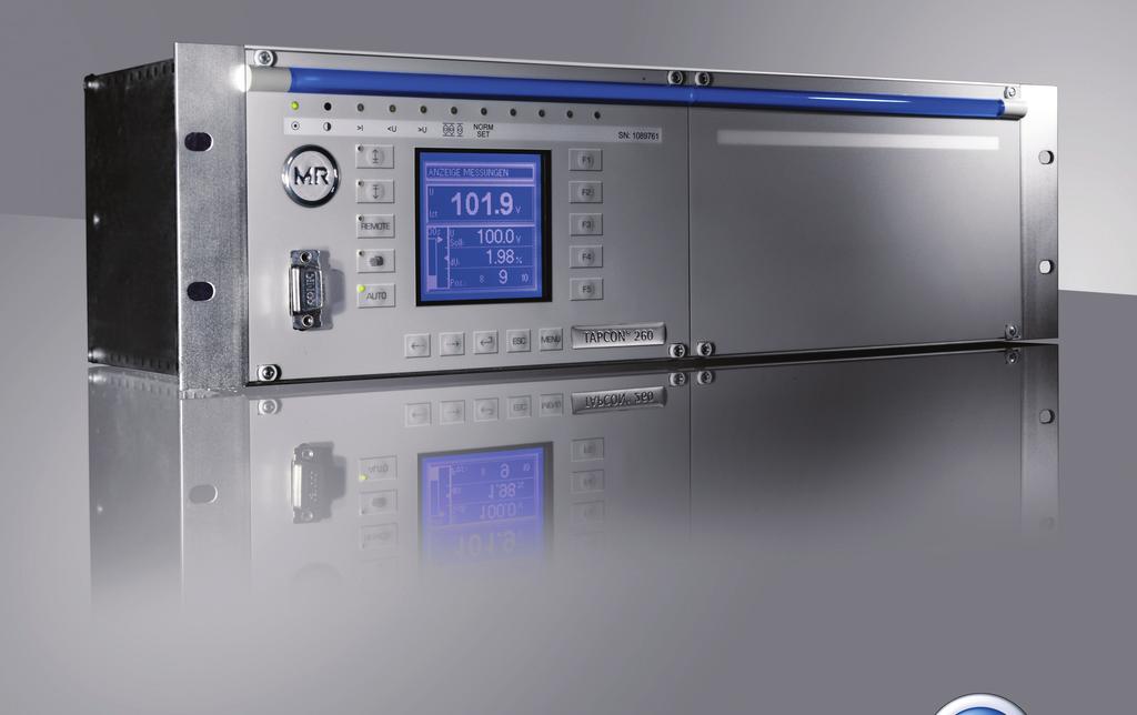
7 2 Voltage regulator connections 2 Voltage regulator connections The physical interfaces RS232, RS485, optional fiber-optic cables and the Ethernet are provided on the Voltage regulator for data transfer via the DNP3 protocol. Figure 1 CIC card 1 RS232 (9 pin female SUB-D connector) 2 RS485 3 Ethernet RJ45 (optional) 4 FH-ST or F-SMA fiber-optic cable in 850 nm or 660 nm (optional) 5 Reset key 6 TxD LED for transmit signal 7 RxD LED for receive signal 8 Clk LED for operating mode (flashes for 2 seconds) 9 Clip for connecting cable shield with functional ground Maschinenfabrik Reinhausen /00 EN TAPCON 260 7
8 2 Voltage regulator connections RS232 RS485 Ethernet (RJ45) Fiber-optic cable (optional) 9 pin female SUB-D connector Pin 2: TxD Pin 3: RxD Pin 5: GND 3 pin connector from Phoenix (MC1.5/3 GF 3.5) Pin 1: GND (100 Ω ground resistance) Pin 2: B (inverted) Pin 3: A (not inverted) Polarity: A > B by 200 mv corresponds to 1. A < B by 200 mv corresponds to 0. An interrupted communication line corresponds to 1. The start bit has the designation 0. Recommended terminating resistor 120 Ω. Pin 1: Tx+ Pin 2: Tx- Pin 3: Rx+ Pin 6: Rx- FH-ST (850 nm or 660 nm) F-SMA (850 nm or 660 nm) Table 2 Interfaces available Transfer on physical plane: Asynchronous with 8 data bits, no parity check, 1 stop bit (8N1) 8 TAPCON /00 EN Maschinenfabrik Reinhausen 2011
9 3 Settings on the voltage regulator 3 Settings on the voltage regulator The following chapters describe how to set the parameters for communication at the relevant interface on the TAPCON 260. > Configuration > Next* > Comm. interface Depending on the product version and software, you will need to press "Next" a varying number of times to reach the "Comm. interface" menu. You will find more information on how to set the parameters in the technical file for TAPCON Communication interface RS232 Communication interface RS232 Baud rate communication 9.6/19.2/38.4 kbaud Fiber-optic cable light ON/OFF not used Local SCADA address 0...9,999 Send delay time not used Table 3 Interface settings RS232 Maschinenfabrik Reinhausen /00 EN TAPCON 260 9
10 3 Settings on the voltage regulator 3.2 Communication interface RS485 Communication interface RS485 Baud rate communication 9.6/19.2/38.4/57.6 kbaud Fiber-optic cable light ON/OFF not used Local SCADA address 0...9, ms (e.g 2 ms, in order to compensate Send delay time for the response time of an external converter RS485/RS232 when switching between transmit and receive operation) Table 4 Interface settings RS Fiber-optic cable (optional) Communication interface Fiber-optic cable Baud rate communication Fiber-optic cable light ON/OFF Local SCADA address 0...9, /19.2/38.4 kbaud ON (1 corresponds to light On) or OFF (1 corresponds to light Off) Send delay time not used Table 5 Interface settings Fiber-optic cable 10 TAPCON /00 EN Maschinenfabrik Reinhausen 2011
11 3 Settings on the voltage regulator 3.4 Ethernet (RJ45) (optional) Communication interface Baud rate communication RJ45 fixed 19.2 kbaud Network address TCP port 1234 Local SCADA address 0...9,999 Send delay time not used Table 6 Interface settings RJ45 Maschinenfabrik Reinhausen /00 EN TAPCON
12
13 4 Data points 4 Data points 4.1 Monitoring direction All spontaneous messages (in the event of changes) are transmitted with a time stamp. The time stamp always relates to when the message is sent. A message caused by a general query is sent without a time stamp Single bit binary inputs: objects 01, variation 01 Point index Name Default Class Assigned to events (1, 2, 3 or ) Name for state when value is 0 Name for state when value is 1 Description 0 Auto/Manual Status 1 Manual Auto Status of Auto/Manual regulation mode 1 Raise 1 Raise command inactive 2 Lower 1 Lower command inactive 3 Desired Voltage Level 1 4 Desired Voltage Level 2 5 Desired Voltage Level 3 6 SI Command 1 1 Desired Voltage Level 1 inactive 1 Desired Voltage Level 2 inactive 1 Desired Voltage Level 3 inactive 1 SI Command 1 inactive Raise command active Lower command active Desired Voltage Level 1 active Desired Voltage Level 2 active Desired Voltage Level 3 active SI Command 1 active When the voltage regulator is setting a raise command When the voltage regulator is setting a lower command Activation status of Desired Voltage Level 1 Activation status of Desired Voltage Level 2 Activation status of Desired Voltage Level 3 Status of SI Command 1 Maschinenfabrik Reinhausen /00 EN TAPCON
14 4 Data points Point index Name Default Class Assigned to events (1, 2, 3 or ) Name for state when value is 0 Name for state when value is 1 Description 7 SI Command 2 8 SI Command 3 9 Motor Drive running 10 Parallel Status 11 Parallel Error 12 Local/Remot e Status 13 User Indication 3 1 SI Command 2 inactive 1 SI Command 3 inactive 1 Motor Drive running 1 Independent Mode SI Command 2 active SI Command 3 active Motor Drive not running Parallel Mode Status of SI Command 2 Status of SI Command 3 Status of input "Motor Drive running" Parallel control status 1 No error Error Parallel error status 1 Local (SCADA controls ignored) 1 User indication 3 inactive Remote (SCADA controls enabled) User indication 3 active Control mode status of voltage regulator Parametrizable indication no.3. The TAPCON 260 has four parameterizable indications. These can be set to an input or to a relay. The indications will be 1 if there is a signal at the parameterized input or if the parameterized relay is ON. 14 Overvoltag e 15 Undervolta ge 16 Overcurren t 1 No overvoltage 1 No undervoltag e 1 No Overcurrent 17 Reserved 1 No Undercurre nt 18 Function Monitoring 19 Reserved 1 1 Normal mode Overvoltage Undervoltag e Overvoltage detection status Undervoltage detection status Overcurrent Overcurrent detection status Undercurren t 15 min out of bandwidth Undercurrent detection status Function Monitoring (15 min out of bandwidth 14 TAPCON /00 EN Maschinenfabrik Reinhausen 2011
15 4 Data points Point index Name Default Class Assigned to events (1, 2, 3 or ) Name for state when value is 0 Name for state when value is 1 Description 20 User Indication 1 21 User Indication 2 22 Parallel Master 23 Parallel Follower 24 Circulating Current 25 User Indication Reserved 1 1 User Indication 1 inactive 1 User Indication 2 inactive 1 Parallel control mode "master" inactive 1 Parallel control mode "follower" inactive 1 Parallel control mode "circulating current" inactive 1 User Indication 4 inactive User Indication 1 active User Indication 2 active Parallel control mode "master" active Parallel control mode "follower" active Parallel control mode "circulating current" active User Indication 4 active Parameterizable indication no. 1 Parametrizable indication no. 2 Status of parallel control mode "Master" Status of parallel control mode "Follower" Status of parallel control mode "Circulating Current" Parameterizable indication no Status Alarm Relay 1 No Alarm Alarm Status of "Status Alarm Relay" Table 7 Binary input point list Maschinenfabrik Reinhausen /00 EN TAPCON
16 4 Data points Example of request/response > [12:04:25] Binary Input request Data Link Header User Data (No Confirm) [DIR:1,PRM:1,FCV:0] Length 11 Dest 1 Source 3 Transport Header [FIN:1,FIR:1,Seq:0] Application Data Read [FIR:1,FIN:1,CON:0,UNS:0,Seq:0] Binary Input (Object 1) Var 0 Qualifier 06x < [12:04:25] Binary Input response Data Link Header User Data (No Confirm) [DIR:0,PRM:1,FCV:0] Length 50 Dest 3 Source 1 Transport Header [FIN:1,FIR:1,Seq:0] Application Data Response [FIR:1,FIN:1,CON:0,UNS:0,Seq:0] [Need Time, Restart] Binary Input (Object 1) Var 1 Qualifier 00x Start 0 Stop 16 DI DI DI 16 0 Binary Input (Object 1) Var 2 Qualifier 00x Start 17 Stop 43 DI 17 0 [Off-line] DI 18 0 [On-line] DI 19 0 [Off-line] DI 20 0 [On-line] DI 21 0 [On-line] DI 22 0 [On-line] DI 23 0 [On-line] DI 24 0 [On-line] DI 25 0 [On-line] DI 27 0 [Off-line] DI 28 0 [Off-line] DI 29 0 [Off-line] DI 30 0 [Off-line] DI 31 0 [Off-line] DI 32 0 [Off-line] DI 33 0 [Off-line] DI 34 0 [Off-line] DI 35 0 [Off-line] DI 36 0 [Off-line] DI 37 0 [Off-line] DI 38 0 [Off-line] DI 39 0 [Off-line] DI 40 0 [Off-line] DI 41 0 [Off-line] DI 42 0 [Off-line] DI 43 0 [Off-line] 16 TAPCON /00 EN Maschinenfabrik Reinhausen 2011
17 4 Data points Binary output status and control relay output block point list Supported control operations Default class Assigned to events (1, 2, 3 or ) Point index Name Select/operate Direct operate Direct operate - No ack Pulse on Pulse off Latch on Latch off Trip Close Count > 1 Cancel currently running operation Name for state when value is 0 Name for state when value is 1 Change Command 0 Auto/ Manual Switch x x x x x x x Manual On Auto On Activation of Auto or Manual voltage regulation method. Pulse/Latch on/off times are fixed hardware dependent. Variable on/off times will be ignored. 1 Raise x x x x x - Raise 2 Lower x x x x x - Lower 3 Desired Voltage Level 1 x x x x x - Select VL 1 4 Desired Voltage Level 2 x x x x x - Select VL 2 5 Desired Voltage Level 3 x x x x x - Select VL 3 6 SI Com- Command 1 x x x x x x SI Command 1 off SI Command 1 on 7 SI Com- Command 2 x x x x x x SI Command 2 off SI Command 2 on 8 SI Com- Command 3 x x x x x x SI Command 3 off SI Command 3 on Maschinenfabrik Reinhausen /00 EN TAPCON
18 4 Data points Supported control operations Default class Assigned to events (1, 2, 3 or ) Point index Name Select/operate Direct operate Direct operate - No ack Pulse on Pulse off Latch on Latch off Trip Close Count > 1 Cancel currently running operation Name for state when value is 0 Name for state when value is 1 Change Command Each of the three "SI Commands" sets a corresponding flag in the TAPCON 260. The status of the flags can be used like an input of the IO or UC module to activate or deactivate a function of the TAPCON Parallel Master x x x x x - Select Parallel Control Mode Master Master method selection Pulse/Latch on/off times are fixed hardware dependent. Variable on/off times will be ignored. 10 Parallel Follower x x x x x - Select Parallel Control Mode Follower Follower method selection Pulse/Latch on/off times are fixed hardware dependent. Variable on/off times will be ignored. 11 Circulatin g Current x x x x x - Select Parallel Control Mode Circulatin g Current Circulating current method selection Pulse/Latch on/off times are fixed hardware dependent. Variable on/off times will be ignored Table 8 Binary output status and control relay output block point list 18 TAPCON /00 EN Maschinenfabrik Reinhausen 2011
19 4 Data points Analog input point lis Point index Name Default class Assigned to events (1, 2, 3 or ) Transmitted value Minimum Maximum Scaling Multiplier Offset Default deadband Units Resolution 0 Desired Voltage Level , V Measured Voltage 2 0 1, V 1 2 Voltage Deviation 2-1,000 2, % 1* *in % of active voltage level 3 Reserved Reserved Measured Current , % 1 6 Tap Position Reserved Table 9 Analog input point list Example of request/response > [14:29:23] Analog Input request Data Link Header User Data (No Confirm) [DIR:1,PRM:1,FCV:0] Length 11 Dest 1 Source 3 Transport Header [FIN:1,FIR:1,Seq:0] Application Data Read [FIR:1,FIN:1,CON:0,UNS:0,Seq:1] Analog Input (Object 30) Var 0 Qualifier 06x < [14:29:24] Unknown Exchange Data Link Header User Data (No Confirm) [DIR:1,PRM:1,FCV:0] Length 11 Dest 1 Source 3 Application Data Read [FIR:0,FIN:1,CON:0,UNS:0,Seq:1] Analog Input (Object 30) Var 0 Qualifier 06x < [14:29:26] Response Timeout Maschinenfabrik Reinhausen /00 EN TAPCON
20 4 Data points Analog output status: object 40, variation 02 Supported control operations Transmitted value Scaling Default class Assigned to events (1, 2, 3 or ) Point Index Name 0 Desired Voltage Level 1 Table 10 Select/Operate Direct Operate Direct Operate No Ack Minimum Maximum Multiplier Offset Units Resolution Change Command x x x 490 1, V 1 Analog output status and analog output control block point list Example of request/response > [14:44:52] Analog Output Status request Data Link Header User Data (No Confirm) [DIR:1,PRM:1,FCV:0] Length 11 Dest 1 Source 3 Transport Header [FIN:1,FIR:1,Seq:0] Application Data Read [FIR:1,FIN:1,CON:0,Uns:0,Seq:2] Analog Output Status (Object 40) Var 0 Qualifier 06x < [14:44:52] Analog Output Status response 05 Data Link Header User Data (No Confirm) [DIR:0,PRM:1,FCV:0] Length 18 Dest 3 Source 1 Transport Header [FIN:1,FIR:1,Seq:0] Application Data Response [FIR:1,FIN:1,CON:0,UNS:0,Seq:0] [Need Time,Restart] Analog Output Status (Object 40) Var 2 Qualifier 00x Start 0 Stop 0 AOs [on-line] 20 TAPCON /00 EN Maschinenfabrik Reinhausen 2011
21 4 Data points 4.2 Control direction The current software version only accepts the control function codes direct operate no ack and direct operate with ack for the commands. Only one command object is allowed in one message. The answer after a direct operate with ack is a copy of the command object. To be sure that the command really has been executed you have to look if the status of the corresponding binary input changes after the command. The code field in the control code object can be pulse on/off and latch on/off. Every command can be given on two adresses (object numbers). The alternative number has an offset of 64. Commands with the alternative number are inverted before they are given to the voltage regulator. Therefore it is possible to switch to manual with an off command with object number 0 or with an on command with object number 64. The remote mode must be set for commands from the control system on TAPCON 260 to be executed on the Voltage regulator. Maschinenfabrik Reinhausen /00 EN TAPCON
22 4 Data points Single bit commands: object 12, variation 01 Input Unit Scale Designation Range value 0 N/A N/A Auto/manual off:manual on:automatic 64 on:manual off:automatic 1 N/A N/A Raise on:pulse to tap changer to raise voltage 65 off: pulse to tap changer to raise voltage 2 N/A N/A Lower on:pulse to tap changer to lower voltage 66 Off: pulse to tap changer to lower voltage 3 Set voltage level 1 on:set voltage level 1 67 The command is available if parameter voltage level delta in the TAPCON 260 is zero and the position of the inputs for remote control of voltage level 2/3 is off. 4 Set voltage level 2 on:set voltage level 2 68 The command is available if parameter voltage level delta in the TAPCON 260 is zero and the position of the inputs for remote control of voltage level 2/3 is off. 5 Set voltage level 3 on:set voltage level 3 Request function 22 TAPCON /00 EN Maschinenfabrik Reinhausen 2011
23 4 Data points Input Unit Scale Designation Range value Request function 69 The command is available if parameter voltage level delta in the TAPCON 260 is zero and the position of the inputs for remote control of voltage level 2/3 is off. 6 SI command 1 on: set flag off: reset flag 70 off: set flag on: reset flag 7 SI command 2 on: set flag off: reset flag 71 off: set flag on: reset flag Each of the three SI commands sets a corresponding flag in the TAPCON 260. The status of the flags can be used like an input of the IO or UC module to activate or deactivate a function of the TAPCON 260. Example: If parameter Input parallel group 1 is set to SI:cmd1 for two TAPCONs then parallel control of these TAPCONs can be switched on/off by setting SI command 1 on/off for both TAPCONs. 10 Parallel control on/off on: parallel control on off: parallel control off 74 off: parallel control on on: parallel control off Parallel control on/off can be written only with some versions of the TAPCON 260 software. Normally, parallel control on/off is only an indication of the current status of the TAP- CON Parallel control mode master on: parallel control mode master on off: automatic selection of parallel control mode master/follower on Maschinenfabrik Reinhausen /00 EN TAPCON
24 4 Data points Input Unit Scale Designation Range value Request function 80 off: parallel control mode master on on: automatic selection of parallel control mode master/follower on Parallel control mode master cannot be set if the TAPCON 260 is set to parallel control mode circulating current. Switching from parallel control mode master to automatic selection of parallel control mode master/follower is also not possible if the TAPCON 260 is set to parallel control mode circulating current. 23 Parallel control mode follower on: parallel control mode follower on off: parallel control mode follower off 81 off: parallel control mode follower on on: parallel control mode follower off Parallel control mode follower cannot be set if the TAPCON 260 is set to parallel control mode circulating current. Table 11 Single bit commands: object 12, variation 01 Example for switching from manual to automatic mode > [14:45:58] Direct Oper Auto request Data Link Header User Data (No Confirm) [DIR:1,PRM:1,FCV:0] Length 24 Dest 1 Source 3 Transport Header [FIN:1,FIR:1,Seq:0] Application Data Direct Operate [FIR:1,FIN:1,CON:0,UNS:0,Seq:1] Control Block (Object 12) Var 1 Qualifier 17x Count 1 DO 0,NULL,Latch Off,Count 1,On/Off Time 1-0 msecs,[accepted] < [14:45:58] Direct Oper Auto response Data Link Header User Data (No Confirm) [DIR:0,PRM:1,FCV:0] Length 26 Dest 3 Source 1 Transport Header [FIN:1,FIR:1,Seq:1] Application Data Response [FIR:1,FIN:1,CON:0,UNS:0,Seq:1] [Need Time,Restart] Control Block (Object 12) Var 1 Qualifier 17x Count 1 DO 0,NULL,Latch Off,Count 1,On/Off Time 1-0 msecs,[accepted] 24 TAPCON /00 EN Maschinenfabrik Reinhausen 2011
25 4 Data points Example for switching from automatic to manual mode > [15:30:30] Direct Oper Manual request Data Link Header User Data (No Confirm) [DIR:1,PRM:1,FCV:0] Length 24 Dest 1 Source 3 Transport Header [FIN:1,FIR:1,Seq:0] Application Data Direct Operate [FIR:1,FIN:1,CON:0,UNS:1,Seq:6] Control Block (Object 12) Var 1 Qualifier 17x Count 1 DO 0,NULL,Latch Off,Count 1,On/Off Time 1-0 msecs,[accepted] < [15:30:30] Direct Oper Manual response Data Link Header User Data (No Confirm) [DIR:0,PRM:1,FCV:0] Length 26 Dest 3 Source 1 Transport Header [FIN:1,FIR:1,Seq:6] Application Data Response [FIR:1,FIN:1,CON:0,UNS:0,Seq:6] [Class 1,Need Time,Restart] Control Block (Object 12) Var 1 Qualifier 17x Count 1 DO 0,NULL,Latch Off,Count 1,On/Off Time 1-0 msecs,[accepted] Example for tap-changer raise > [15:33:18] Direct Oper Hoeher request Data Link Header User Data (No Confirm) [DIR:1,PRM:1,FCV:0] Length 24 Dest 1 Source 3 Transport Header [FIN:1,FIR:1,Seq:0] Application Data Direct Operate [FIR:1,FIN:1,CON:0,UNS:0,Seq:7] Control Block (Object 12) Var 1 Qualifier 17x Count 1 DO 1,NULL,Latch On,Count 1,On/Off Time 1-0 msecs,[accepted] < [15:33:18] Direct Oper Hoeher response Data Link Header User Data (No Confirm) [DIR:0,PRM:1,FCV:0] Length 26 Dest 3 Source 1 Transport Header [FIN:1,FIR:1,Seq:7] Application Data Response [FIR:1,FIN:1,CON:0,UNS:0,Seq:7] Control Block (Object 12) Var 1 Qualifier 17x Count 1 DO 1,NULL,Latch On,Count 1,On/Off Time 1-0 msecs,[accepted] Maschinenfabrik Reinhausen /00 EN TAPCON
26
27 5 Configuration 5 Configuration 5.1 Unsolicited messages If unsolicited messages are enabled the status of the binary inputs will be sent if one of them has changed. The analog inputs will be sent if the tap position has changed. The current protocol software can only enable/disable all unsolicited messages together. If a message with function code enable/disable unsolicited messages is detected the complete mechanism will be enabled or disabled. Example for enabling unsolicited messages > [15:39:57] Enable Unsolicited request Data Link Header User Data (No Confirm) [DIR:1,PRM:1,FCV:0] Length 17 Dest 1 Source 3 Transport Header [FIN:1,FIR:1,Seq:0] Application Data Disable Unsolicited Messages [FIR:1,FIN:1,CON:0,UNS:0,Seq:1] Class Data (Object 60) Var 2 Qualifier 06x Class Data (Object 60) Var 3 Qualifier 06x Class Data (Object 60) Var 4 Qualifier 06x < [15:39:57] Enable Unsolicited response Data Link Header User Data (No Confirm) [DIR:0,PRM:1,FCV:0] Length 10 Dest 3 Source 1 Transport Header [FIN:1,FIR:1,Seq:8] Application Data Response [FIR:1,FIN:1,CON:0,UNS:0,Seq:0] [Class 1,Need Time,Restart,Bad FC] Example for disabling unsolicited messages > [15:43:47] Disable Unsolicited request Data Link Header User Data (No Confirm) [DIR:1,PRM:1,FCV:0] Length 17 Dest 1 Source 3 Transport Header [FIN:1,FIR:1,Seq:0] Application Data Disable Unsolicited Messages [FIR:1,FIN:1,CON:0,UNS:0,Seq:1] Class Data (Object 60) Var 2 Qualifier 06x Class Data (Object 60) Var 3 Qualifier 06x Class Data (Object 60) Var 4 Qualifier 06x < [15:43:47] Disable Unsolicited response Data Link Header User Data (No Confirm) [DIR:0,PRM:1,FCV:0] Length 10 Dest 3 Source 1 Transport Header [FIN:1,FIR:1,Seq:9] Application Data Response [FIR:1,FIN:1,CON:0,UNS:0,Seq:1] [Class 1,Need Time,Restart,Bad FC Maschinenfabrik Reinhausen /00 EN TAPCON
28 5 Configuration Example for an unsolicited response of binary input > [15:49:34] Binary Input Change response Data Link Header User Data (No Confirm) [DIR:0,PRM:1,FCV:0] Length 36 Dest 3 Source 1 Transport Header [FIN:1,FIR:1,Seq:39] Application Data Unsolicited Message [FIR:1,FIN:1,CON:1,UNS:1,Seq:8] [Local] Time and Date CTO (Object 51) Var 1 Qualifier 07x Count 1 12/16/10 15:49: Binary Input Change (Object 2) Var 3 Qualifier 17x Count 3 DI 0 1 [On-line] 12/16/10 15:49: DI 0 0 [On-line] 15:49: DI 0 1 [On-line] 12/16/10 15:49: Example for an unsolicited response of analog input > [15:58:18] Analog Change Event response Data Link Header User Data (No Confirm) [DIR:0,PRM:1,FCV:0] Length 32 Dest 3 Source 1 Transport Header [FIN:1,FIR:1,Seq:12] Application Data Unsolicited Message [FIR:1,FIN:1,CON:1,UNS:1,Seq:8] [Local] Analog Change Event (Object 32) Var 1 Qualifier 17x Count 3 AI 6 2 [On-line] AI 6 3 [On-Line] AI 6 2 [On-Line] 5.2 Internal indications bits class 1 data available and class 2 data available The bit class 1 data available will be set if one of the binary input values has changed. The bit class 2 data available will be set if the tap position value has changed. If unsolicited messages are disabled the bits will be reset if the corresponding data messages have been sent. 28 TAPCON /00 EN Maschinenfabrik Reinhausen 2011
29
30 /00 EN 04/11 Maschinenfabrik Reinhausen GmbH Falkensteinstrasse Regensburg Phone: Fax: sales@reinhausen.com
Voltage regulator TAPCON 260
 Voltage regulator TAPCON 260 Supplement 2531964/00 Protocol description for IEC 60870-5-101 All rights reserved by Maschinenfabrik Reinhausen Copying and distribution of this document and utilization and
Voltage regulator TAPCON 260
 Voltage regulator TAPCON 260 Supplement 2531994/01 Protocol description MODBUS All rights reserved by Maschinenfabrik Reinhausen Copying and distribution of this document and utilization and communication
Voltage regulator TAPCON 240
 Voltage regulator TAPCON 240 Supplement 2398420/00 Protocol description SPA-Bus All rights reserved by Maschinenfabrik Reinhausen Copying and distribution of this document and utilization and communication
Monitoringsystem TAPGUARD 260
 Monitoringsystem TAPGUARD 260 Supplement 2205023/01 Protocol description IEC 60870-5-101 All rights reserved by Maschinenfabrik Reinhausen Copying and distribution of this document and utilization and
Monitoringsystem TAPGUARD 260
 Monitoringsystem TAPGUARD 260 Supplement 2205022/01 Protocol description IEC 60870-5-103 All rights reserved by Maschinenfabrik Reinhausen Copying and distribution of this document and utilization and
Voltage Regulator TAPCON 230 expert
 www.reinhausen.com Voltage Regulator TAPCON 230 expert Supplement 2195774 to Operating Instructions 2136339 Device Profile Document MODBUS 2009 All rights reserved, Maschinenfabrik Reinhausen Unauthorised
Voltage regulator TAPCON 240
 Voltage regulator TAPCON 240 Supplement 2398461/01 Protocol description DNP3 All rights reserved by Maschinenfabrik Reinhausen Copying and distribution of this document and utilization and communication
Laststufenschalter. Supplement. Betriebsanleitung. Device Profile Document MODBUS
 Laststufenschalter Voltage Regulator TAPCON VACUTAP 230 VRAVT I HD Betriebsanleitung Supplement Device Profile Document MODBUS Alle Rechte bei Maschinenfabrik Reinhausen Weitergabe sowie Vervielfältigung
TAPCON 250 DIGITAL ON-LOAD TAP-CHANGER CONTROLLER FOR VOLTAGE REGULATING TRANSFORMERS.
 TAPCON 250 DIGITAL ON-LOAD TAP-CHANGER CONTROLLER FOR VOLTAGE REGULATING TRANSFORMERS. WWW.REINHAUSEN.COM TAPCON 250 TAPCON 250 THE NEW GENERATION OF VOLTAGE CONTROLLERS. For more than 40 years voltage
tapcon 230 user-friendly, FleXiBle and reliable. transformer control
 tapcon 230 user-friendly, FleXiBle and reliable. transformer control Tapcon 230 tapcon 230 the new standard in voltage control. 2 Maschinenfabrik Reinhausen (MR) has been developing and manufacturing voltage
TAPCON 240 Voltage Regulator for Regulating Transformers
 www.reinhausen.com TAPCON 240 Voltage Regulator for Regulating Transformers TAPCON The next generation of voltage regulators TAPCON : a name which is synonymous for an entirely new and ground-breaking
TAPCON 230 Voltage Regulator for Regulating Transformers
 www.reinhausen.com TAPCON 230 Voltage Regulator for Regulating Transformers TAPCON Voltage regulators of the next generation TAPCON : a name which stands for a completely new range of voltage regulators
Voltage Regulator TAPCON 230 expert
 Voltage Regulator TAPCON 230 expert Supplement 2195774/01 EN. Protocol Specification MODBUS All rights reserved by Maschinenfabrik Reinhausen Dissemination and reproduction of this document and use and
Analog display for resistance current
 www.reinhausen.com Analog display for resistance current Operating Instructions BA 2220061/01 NOTE The product may have been modified after this document went to press. We expressly reserve the right to
TAPCON NEXT-GENERATION VOLTAGE REGULATORS. transformer control
 TAPCON NEXT-GENERATION VOLTAGE REGULATORS. transformer control Tapcon tapcon VOLTAGE REGULATION FOR TOMORROW S CHALLENGES. 2 For more than 40 years voltage regulators of the tapcon series have stood for
Trafoguard reliable monitoring of Transformer operating statuses. Transformer control
 Trafoguard reliable monitoring of Transformer operating statuses. Transformer control 2 Trafoguard Trafoguard money can't buy a better way of ensuring economic Transformer operation. Trafoguard Trafoguard
TAPCON NEXT-GENERATION VOLTAGE REGULATORS. transformer control
 TAPCON NEXT-GENERATION VOLTAGE REGULATORS. transformer control Tapcon tapcon VOLTAGE REGULATION for the challenges of tomorrow. 2 for more than 40 years voltage regulators from the tapcon series have been
Voltage Regulator TAPCON 240
 Voltage Regulator TAPCON 240 Supplement 2397996/01 EN. Protocol specification IEC 60870-5-101 All rights reserved by Maschinenfabrik Reinhausen Dissemination and reproduction of this document and use and
GE MDS, LLC. NETio Series. Protocol Communications Supplement. March 2013 Part No A01, Rev. C
 GE MDS, LLC. NETio Series Protocol Communications Supplement March 2013 Part No. 05-4672A01, Rev. C Modbus Protocol NETio Architectural Implementation As described in detail below, the Modbus RTU protocol
A36D/TPSD DNP 3.0 & Modbus SCADA INTERFACE
 SCADA INTERFACE INSTRUCTIONS - OPTION 21P / 21Q - FOR A36D/TPSD SYSTEMS A36D/TPSD DNP 3.0 & Modbus SCADA INTERFACE OPTION 21P / 21Q INSTRUCTIONS This manual is only valid for A36D/TPSD Chargers equipped
EVO AT SERIES BATTERY CHARGER AT SERIES BATTERY CHARGER COMMUNICATIONS MANUAL. EVO - Microprocessor Controlled Float Battery Charger JA
 EVO P R O D U C T COMMUNICATIONS MANUAL EVO - Microprocessor Controlled Float Battery Charger JA5011-54 NOTICE! WARNING Table of Contents - ATevo TABLE OF CONTENTS 1. INTRODUCTION.....................................................
DNP 3.0 & Modbus SCADA INTERFACE INSTRUCTIONS FOR 205T BASED SYSTEMS
 DNP 3.0 & Modbus SCADA INTERFACE INSTRUCTIONS - OPTION 21PQ - FOR 205T BASED SYSTEMS DNP 3.0 & Modbus SCADA INTERFACE OPTION 21PQ INSTRUCTIONS FOR 205T BASED SYSTEMS CPN114830 ECN/DATE ISSUE DATE: ECN
Monitoring system TAPGUARD 240. Operating Instructions 244/04
 Monitoring system TAPGUARD 240 Operating Instructions 244/04 All rights reserved by Maschinenfabrik Reinhausen Copying and distribution of this document and utilization and communication of its contents
PACSystems* RX3i IC695CMM002 and IC695CMM004
 May 2010 PACSystems* RX3i IC695CMM002 and IC695CMM004 Serial Communications Modules PACSystems* RX3i Serial Communications modules expand the serial communications capabilities of the RX3i system. Serial
350 Feeder Management System
 Title page GE Digital Energy Multilin 350 Feeder Management System Feeder Protection and Control Communications Guide SR350 revision: 1.20 Manual P/N: 1601-9087-A2 GE publication code: GEK-113511B Copyright
345 Transformer Protection System
 GE Digital Energy 345 Transformer Protection System Transformer protection and control GE Digital Energy 650 Markland Street Markham, Ontario Canada L6C 0M1 TELEPHONE: Worldwide +1 905 927 7070 Europe/Middle
Digital On-Load Tap Changer Voltage Controller TAPCON 250 Operating Instructions (short version) BA 289
 BA 289") www.reinhausen.com Digital On-Load Tap Changer Voltage Controller Operating Instructions (short version) BA 289 Defined movement of the drive shaft REGULATING TRANSFORMER Changing the Transformer Ratio
www.reinhausen.com Digital On-Load Tap Changer Voltage Controller Operating Instructions (short version) BA 289 Defined movement of the drive shaft REGULATING TRANSFORMER Changing the Transformer Ratio
DNP Points List and Implementation
 S&C IntelliCap Plus Automatic Capacitor Control DNP Points List and Implementation Table of Contents Section Page Section Page DNP Points List for IntelliCap Plus Controls...1 Status Points....2 Analog
Device Profile Document
 Voltage Regulators CL-6A Regulator Control DNP3 Device Profile Document Reference Information R225-90-11 Device Profile Document For Communications Protocol DNP3 For Use With Cooper Power Systems CL-6A
DNP3 V3.00 DEVICE PROFILE DOCUMENT
 DNP3 V3.00 DEVICE PROFILE DOCUMENT Vendor Name: DAQ Electronics. Device Name: DNP3 Master Station Server in the Callisto Computer. Date: June 8, 2000 Highest DNP Level Supported: For Requests: DNP-L3.
CURRENT PROTECTION RELAY SMPR-1
 CURRENT PROTECTION RELAY SMPR-1 1.- ORION ITALIA SERIES MODBUS PROTOCOL. The ORION ITALIA SERIES implement a subset of the AEG Modicon Modbus serial communication standard. Many devices support this protocol
MSENSE BM MONITORING FOR BUSHINGS.
 MSENSE BM MONITORING FOR BUSHINGS. WWW.REINHAUSEN.COM MSENSE BM Monitoring of three high-voltage bushings with reference system Voltage transformer (high-voltage side) ΔC1comp Δtan δ1comp t MSENSE BM t
Technical Documentation
 BLR-CM - MODBUS Technical Documentation BLR-CM MODBUS Beluk GmbH Tel.: +49/(0)8861/2332-0 Fax: +49/(0)8861/2332-22 e-mail: blr@beluk.de http://www.beluk.de BLR-CM - MODBUS Page 2 of 20 Document history
1. Introduction. 2. Installation MODBUS INTERFACE
 5551.C 8473.C MODBUS INTERFACE PIM-MB-1 Modbus Interface 1. Introduction AuCom soft starters can be controlled and monitored across an RS485 serial communication network using the Modbus RTU and AP ASCII
PACSystems* RX3i IC695CMM002 and IC695CMM004
 April 2010 PACSystems* RX3i IC695CMM002 and IC695CMM004 Serial Communications Modules PACSystems * RX3i Serial Communications modules expand the serial communications capabilities of the RX3i system. Serial
DNP Points List and Implementation for the 6802 Vista Control
 S&C 6800 Series Automatic Switch Control DNP Points List and Implementation for the 6802 Vista Control Table of Contents Section Page Section Page DNP Points List for 6802 Vista Control...1 6802 Status
It is the installer's responsibility to follow all instructions in this manual and to follow correct electrical practice.
 MCD Modbus Module Instructions Important User Information INSTALLATION INSTRUCTIONS: MCD MODBUS MODULE Order Code: 175G9000 1. Important User Information Observe all necessary safety precautions when controlling
SCADA Controlled LOR/ER - DNP3.0 Communications Protocol - TECHNICAL MANUAL ES-SLOR-1
 SCADA Controlled LOR/ER - DNP3.0 Communications Protocol - TECHNICAL MANUAL ES-SLOR-1 Telephone: 781-335-5200 fax: 781-335-4253 180 King Avenue Weymouth, MA 02188 www.electroswitch.com 1 Introduction...
DNP 3.0 Serial (RS232/RS485) and Ethernet (TCP/IP) SCADA Interface for TPSD/A36D Chargers with S2A-205T Option 21P or 57T or 57U. Setup Instructions
 and Ethernet (TCP/IP) SCADA Interface for TPSD/A36D Chargers with S2A-205T Option 21P or 57T or 57U. Setup Instructions") La Marche Manufacturing Company www.lamarchemfg.com DNP 3.0 Serial (RS232/RS485) and Ethernet (TCP/IP) SCADA Interface for TPSD/A36D Chargers with S2A-205T Option 21P or 57T or 57U Setup Instructions This
La Marche Manufacturing Company www.lamarchemfg.com DNP 3.0 Serial (RS232/RS485) and Ethernet (TCP/IP) SCADA Interface for TPSD/A36D Chargers with S2A-205T Option 21P or 57T or 57U Setup Instructions This
Voltage Regulator TAPCON
 Voltage Regulator TAPCON Operating Instructions 3587317/10 EN All rights reserved by Maschinenfabrik Reinhausen Dissemination and reproduction of this document and use and disclosure of its content are
7SR242 Duobias Multi-Function 2-Winding Transformer Protection Relay
 7SR242 Duobias Multi-Function 2-Winding Transformer Protection Relay Document Release History This document is issue 2010/06. The list of revisions up to and including this issue is: 2010/06 Additional
REL 512 Connectivity With A Harris Westronics RTU Using DNP 3.0
 ABB Application Note Substation Automation and Protection Division REL 512 AN-45A-99 REL 512 Connectivity With A Harris Westronics RTU Using DNP 3.0 ABSTRACT: DNP 3.0 is a popular communication protocol
KTA-250 Anemometer Alarm Card
 Connects to Davis Instruments DS7911 Anemometer Monitor both the wind speed and direction Interface to PLCs using the Modbus protocol Communicate via RS232 or 2-wire RS485 Interface to PLCs/Instruments
PAC BI-DP BIM and 8701-CA-BI Carrier
 June 2013 PAC8000 8507-BI-DP BIM and 8701-CA-BI Carrier PROFIBUS DP Bus Interface Module and Carrier The 8507-BI-DP Bus Interface Module (BIM) provides the communications link between the PAC8000 series
DNP3 Communication User's manual
 MV Network Management Fault tracking Monitoring and Control Merlin Gerin Easergy Range T200 P, T200 I DNP3 Communication User's manual Summary General...2 Functionnalities...2 Characteristics...2 Connection
MODBUS RTU MODULE INSTRUCTIONS. for use with WSIQ2/WSE
 INSTRUCTIONS MODBUS RTU MODULE for use with WSIQ2/WSE WorldWide Electric Corporation Phone: 1-8-88-2131 Fax: 1-8-711-1616 www.worldwideelectric.net Product Compatibility This communications module is suitable
Tap Manager TM100. Operating Instructions
 Tap Manager TM100 Operating Instructions 2 Contents Contents 1 General... 5 1.1 Safety instructions... 5 1.2 Application... 5 2 Design... 6 2.1 Controls... 6 2.1.1 Scroll keys in display field... 6 2.1.2
DNP3 Communications Protocol
 Powermeter and Power Quality Analyzer PM174 DNP3 Communications Protocol Reference Guide BG0413 Rev. A3 Every effort has been made to ensure that the material herein is complete and accurate. However,
Motors Automation Energy Transmission & Distribution Coatings. Profibus DP SRW 01. User s Manual
 Motors Automation Energy Transmission & Distribution Coatings Profibus DP SRW 01 User s Manual Profibus DP User s Manual Series: SRW 01 Firmware Version: V6.0X Language: English Document Number: 10000521541
Copyright: December 2017 Nidec Issue: E
 General Information The manufacturer accepts no liability for any consequences resulting from inappropriate, negligent or incorrect installation or adjustment of the optional parameters of the equipment
7SR21 Non-Directional 7SR22 Directional Overcurrent Relay
 7SR21 Non-Directional 7SR22 Directional Overcurrent Relay Document Release History This document is issue 2010/05. The list of revisions up to and including this issue is: 2010/05 Additional Comms module
DNP3 Device Profile. Device Profile Template. Data Dictionary. Release 2.0. January 30, 2001
 Reclosers Kyle Form 4C Recloser Control Serial Communications Reference Information R280-90-1 DNP3 Device Profile Device Profile Template Data Dictionary Release 2.0 January 30, 2001 For Use With Cooper
Document Name: User Manual for SC10MK, Modbus RTU to Modbus TCP Converter
 Document Name: User Manual for SC10MK, Modbus RTU to Modbus TCP Converter Login for the first time, please use http://192.168.1.100 To key in user name and password is for identifying authorization. Default
BLR-CM Modbus. Technical Documentation. Technical Documentation. Rev BLR-CM Modbus. Beluk GmbH Taubenstrasse Schongau Germany
 Beluk GmbH Taubenstrasse 1 86956 Schongau Germany Tel.: +49/(0)8861/2332-0 Fax: +49/(0)8861/2332-22 E-Mail: blr@beluk.de Web: http://www.beluk.de Document history Date Name Revision Comment 08.11.06 ATh
vacon nx ac drives brake chopper unit (bcu) application user s manual
 application user s manual") vacon nx ac drives brake chopper unit (bcu) application user s manual 2 vacon Introduction Vacon Brake Chopper Unit application INDEX Document code: DPD01565A Software code: ABFIFF01V113 Date: 27.3.2014
vacon nx ac drives brake chopper unit (bcu) application user s manual 2 vacon Introduction Vacon Brake Chopper Unit application INDEX Document code: DPD01565A Software code: ABFIFF01V113 Date: 27.3.2014
Voltage Controller TAPCON 250
 www.reinhausen.com Voltage Controller TAPCON 250 Quick Reference Guide 2009 All rights reserved, Maschinenfabrik Reinhausen Unauthorised copying and distribution of this document and the utilisation and
MXPLC. Compact PLC process station. Summary. Application HVAC control systems, data acquisition, interfacing 3 rd party systems.
 MXPLC Compact PLC process station Summary The MXPLC is a programmable process station with integrated I/O module with the I/O mix optimized for larger HVAC control applications. The multi-interface process
DNP Points List and Implementation for Universal Controls
 S&C 6800 Series Automatic Switch Control DNP Points List and Implementation for Universal Controls Table of Contents Section Page Section Page DNP Points List for 6801 Universal Controls...1 6801 Status
The Multilin DGCV Voltage Regulator Controller
 GE Digital Energy The Multilin DGCV Voltage Regulator Controller Multilin DGCV Revision: 1.10 Manual P/N: 1601-0263-A1 GE publication code: GEK-113581 Copyright 2011 GE Digital Energy Communications Guide
User Guide. Modbus Module. For Digistart soft starters. Part Number: Issue: 3.
 User Guide Modbus Module For Digistart soft starters Part Number: 477-9-3 Issue: 3 General Information The manufacturer accepts no liability for any consequences resulting from inappropriate, negligent
DNP Points List and Implementation
 S&C 6800 Series Automatic Switch Control DNP Points List and Implementation Table of Contents Section Page Section Page DNP Points List for 6801 Controls...1 6801 Status Points...2 6801 Double-bit Status
Industrial Serial Device Server
 1. Quick Start Guide This quick start guide describes how to install and use the Industrial Serial Device Server. Capable of operating at temperature extremes of -10 C to +60 C, this is the Serial Device
PACSystems* RX3i IC695CMM002-EG and IC695CMM002CA-EG IC695CMM004-EG, IC695CMM004CA-EG, and IC695CMM004LT-EG
 September 2017 PACSystems* RX3i IC695CMM002-EG and IC695CMM002CA-EG IC695CMM004-EG, IC695CMM004CA-EG, and IC695CMM004LT-EG Serial Communications Modules PACSystems* RX3i Serial Communications modules expand
Protection Terminal REF 54_ Protection Relay REX 521
 Protection Terminal Protection Relay 1MRS755260 Issued: 02.04.2004 Version: C/22.06.2004 Protection Terminal Protection Relay Contents 1. About this manual...4 1.1. Copyrights...4 1.2. Trademarks...4
DNP3 Field Device Profile. for
 DNP3 Field Device Profile for Document Name: Eaton DNP3 XML File Revision History Date Time ion Reason for change Edited by 2012-01-11 2015-04-16 1 Initial ion Joerg Katzer 15:00:00 2 First updates Joerg
RTU TELEM MODULES TELEM-DO8, TELEM-DI24 and TELEM-AI12 (REMOTE TERMINAL UNIT)
") RTU TELEM MODULES TELEM-DO8, TELEM-DI24 and TELEM-AI12 (REMOTE TERMINAL UNIT) USER S MANUAL Technical documentation, programming, installation and setup instructions, drawings 2001 Table of contents 1.
RTU TELEM MODULES TELEM-DO8, TELEM-DI24 and TELEM-AI12 (REMOTE TERMINAL UNIT) USER S MANUAL Technical documentation, programming, installation and setup instructions, drawings 2001 Table of contents 1.
Data Sheet Rev DALLIS Serial Data
 Lawo AG, Germany Phone: +9 00-0 Web: www.lawo.de Data Sheet Rev. 00-0-0 DALLIS Serial Data Port serial multi-format data converter 9/ Serial Data bidirectional data Ports, data rates up to 00 bps Supports
GRIDCON itap ON-LOAD TAP-CHANGER FOR DISTRIBUTION GRIDS. POWER QUALITY
 GRIDCON itap ON-LOAD TAP-CHANGER FOR DISTRIBUTION GRIDS. POWER QUALITY GRIDCON itap ECONOMICALLY INTEGRATING RENEWABLE ENERGIES INTO THE GRID. RUNNING INDUSTRIAL PROCESSES STABLY WHILE OPTIMIZING ENERGY
Operating instructions. and commissioning instructions
 On-load Regulator Voltage tap-changer TAPCON VACUTAP 230 VR AVTI HD Operating instructions Installation and commissioning instructions All rights reserved, Maschinenfabrik Reinhausen Unauthorized copying
DNP 3.0 device profile for AQ (5) DNP 3.0 device profile for AQ 200
 DNP 3.0 device profile for AQ 200") DNP 3.0 device profile for AQ 200 1 (5) DNP 3.0 device profile for AQ 200 DNP 3.0 device profile for AQ 200 2 (5) Revision: 4.0 Date: October 2018 Changes: - Added Counter support Checked By: DNP 3.0 device
DNP 3.0 device profile for AQ 200 1 (5) DNP 3.0 device profile for AQ 200 DNP 3.0 device profile for AQ 200 2 (5) Revision: 4.0 Date: October 2018 Changes: - Added Counter support Checked By: DNP 3.0 device
APPLICATION NOTE IDM.011
 Description: Steps to follow: Explains how to use the IDM240-5EI and IDM640-8EI drives with RS-485 serial communication, including how to setup the drives for RS-485 communication, recommended connections
T1K MODBUS Base Controller Specifications
 Base Controller 1 2 In This Chapter.... Base Controller Setting the DIP Switches Setting the Rotary Address Switches Port Pin out and Wiring RJ12 Serial Port Pin out and Wiring 2 2 Base Controller General
Setup Instructions. This manual is only valid for A12B Chargers equipped with the following: S2A-225C card with software version P225C0630
 La Marche Manufacturing Company www.lamarchemfg.com DNP 3.0 Serial (RS232/RS485) and Ethernet (TCP/IP) or Fiber SCADA Interface for A12B Chargers Option 21P Option 57T Option 57U Setup Instructions This
DUAL LOOP DETECTOR WITH MODBUS COMMUNICATIONS
 LD220 DUAL LOOP DETECTOR WITH MODBUS COMMUNICATIONS USER MANUAL P.O.Box 24 STANFIELD 3613 SOUTH AFRICA Tel: +27 (031) 7028033 Fax: +27 (031) 7028041 Email: proconel@proconel.com Web: www.proconel.com 18/08/2005
ILBPB24DO32. Inline Block IO Module for PROFIBUS With 32 Digital Outputs. AUTOMATIONWORX Data Sheet 6889_en_04. Description
 Inline Block IO Module for PROFIBUS With 32 Digital Outputs AUTOMATIONWORX Data Sheet 6889_en_04 Description PHOENIX CONTACT - 03/2007 & & ' ) The ILB PB 24 DO32 module is designed for use within a PROFIBUS
W&T Manual Interface modules W&T
 Manual Subject to error and alteration Model 18801, 18811 18802, 18812 18803, 18813, 18833 18601, 18611 18602, 18612 18613, 18633 18401, 18411 18402, 18412 Release 1.7 43 09/2013 by Wiesemann und Theis
Campbell Scientific Australia DNP3 DEVICE PROFILE
 S.UTLEY 1 1 Campbell Scientific Australia DNP3 DEVICE PROFILE Real-time monitoring and Control Systems S.UTLEY 1 2 DNP3 v.28 Device Profile Document Vendor name: Campbell Scientific, Inc. Device Name:
ACE PLUS CORP. APCON100 series Operation Manual RS-232 to Ethernet Converter
 APCON100 series Operation Manual RS-232 to Ethernet Converter Page 1 of 24 APCON100 series Operation Manual Index Chapter 1 Specifications 2 Chapter 2 Introduction 3 Chapter 3 Easy Installation 4 Chapter
SMART RELAY SRW 01 V4.0X
 Motors Automation Energy Transmission & Distribution Coatings SMART RELAY SRW 01 V4.0X Profibus DP Communication Manual Profibus DP Communication Manual Series: SRW 01 Firmware Version: V4.0X Language:
Operator Manual for Profibus
 PROCESS ANALYSERS SERVOPRO MultiExact Operator Manual for Profibus Part Number: Revision: Language: 05410007A 0 UK English This page intentionally blank LIST OF CONTENTS Section Page 1. DESCRIPTION AND
A12B DNP 3.0 SERIAL & ETHERNET (TCP/IP) SCADA INTERFACE
 SCADA INTERFACE") A12B DNP 3.0 SERIAL & ETHERNET (TCP/IP) SCADA INTERFACE OPTION 21P INSTRUCTIONS This manual is only valid for A12B units equipped with a S2A-225C control module and a S2A-383S-3X20 communications card.
A12B DNP 3.0 SERIAL & ETHERNET (TCP/IP) SCADA INTERFACE OPTION 21P INSTRUCTIONS This manual is only valid for A12B units equipped with a S2A-225C control module and a S2A-383S-3X20 communications card.
ENVIRORANGER ERS 500 NVIRORANGER ERS 500 COMMUNICATIONS REFERENCE. Instruction Manual August 2001
 ENVIRORANGER ERS 500 COMMUNICATIONS REFERENCE Instruction Manual August 2001 NVIRORANGER ERS 500 Safety Guidelines Warning notices must be observed to ensure personal safety as well as that of others,
BACnet Protocol Implementation Conformance Statement
 BACnet Protocol Implementation Conformance Statement Date: December 1 st, 2015 Vendor Name: Danfoss A/S Product Name: VLT HVAC Drive FC-102 Product Model Number: FC-102 Applications Software Version: 1.6
RS232/RS422 INTERFACE SETUP MANUAL FOR PHV Series High Voltage POWER SUPPLY Document: Rev A
 RS232/RS422 INTERFACE SETUP MANUAL FOR PHV Series High Voltage POWER SUPPLY Document: TDK-LAMBDA AMERICAS 405 Essex Road, Neptune, NJ 07753 Tel: (732) 795-4149 Fax: (732) 922-9334 Web: www.us.tdk-lambda.com/hp
LATCHING FIBER OPTIC 1xN SWITCHES
 LATCHING FIBER OPTIC 1xN SWITCHES OVERVIEW The fiber optic LATCHING 1xN switches are very fast bidirectional opto-mechanical switches based on the MEMS technology. The component makes an optical connection
ATK3 I/O Module (Modbus Slave)
") ATK3 I/O Module (Modbus Slave) 2011-01-13 The ATK3 I/O Module by ElectroCom Table of contents 2011-01-13...1 The ATK3 I/O Module by ElectroCom...1 1 Hardware...2 1.1 Inputs...3 1.2 Outputs...3 1.2.1 Relay...3
ATK3 I/O Module (Modbus Slave) 2011-01-13 The ATK3 I/O Module by ElectroCom Table of contents 2011-01-13...1 The ATK3 I/O Module by ElectroCom...1 1 Hardware...2 1.1 Inputs...3 1.2 Outputs...3 1.2.1 Relay...3
DEH System SM-3 Step Voltage Regulator Control. Siemens Format B Group 1 and 2 Protocol Guide
 g DEH40281 System SM-3 Step Voltage Regulator Control Siemens Format B Group 1 and 2 Protocol Guide Table of Contents Chapter 1 Introduction About the SM-3...1 About this Guide...1 Chapter 2 Siemens Format
Digital Tapchanger Control M-2001B
 CONTROLS igital Tapchanger Control M-2001B igital Tapchanger Control for Transformers and Regulators Microcontroller-based LTC transformer and regulator control provides reliable operation and expanded
1. System Topology Required Equipment and Components Hardware Equipment Software Equipment... 6
 Contents Moxa Technical Support Team support@moxa.com 1. System Topology... 2 2. Required Equipment and Components... 5 2.1. Hardware Equipment... 5 2.2. Software Equipment... 6 3. Schneider SCADAPack
DeviceNet Interface User Manual
 Documentation of the DeviceNet Interface of the following Drives: - E1100-DN (-HC, XC) - E1100-GP (-HC, XC) - E1130-DP (-HC, XC) - B1100-GP (-HC, XC) DeviceNet Interface User Manual 2013 NTI AG This work
RTU560 Connections and Settings DIN Rail RTU 560CIG10
 Connections and Settings DIN Rail RTU 560CIG10 Application, characteristics and technical data have to be taken from the hardware data sheet: 560CIG10 1KGT 150 719 Operation The 560CIG10 is a DIN rail
GW-7238D J1939 to Modbus TCP Server / RTU Slave Gateway
 GW-7238D J1939 to Modbus TCP Server / RTU Slave Gateway User s Manual www.icpdas.com 1 Warranty All products manufactured by ICP DAS are under warranty regarding defective materials for a period of one
IT 1910i. Industrial 2D-code hand-held scanner TECHNICAL DESCRIPTION. make technical changes EN /06. We reserve the right to
 IT 1910i Industrial 2D-code hand-held scanner EN 50123791 2013/06 We reserve the right to make technical changes TECHNICAL DESCRIPTION 2013 Leuze electronic GmbH + Co. KG In der Braike 1 D-73277 Owen /
ICP DAS. ICP DAS 2015 M2M WLAN Wireless Solutions
 ICP DAS 2015 M2M WLAN Wireless Solutions Industrial Computer Industrial Product Data Computer Acquisition Product System Data Acquisition System PAC WLAN Wireless Solutions Wi-Fi Products WLAN Converter
A Issue A Original. Instruction Manual. nxds Serial Comms Interface
 Instruction Manual A735-01-860 Issue A Original nxds Serial Comms Interface Description nxds6i nxds10i nxds15i nxds20i Item Number A735-01-983 A736-01-983 A737-01-983 A738-01-983 nxds6ic nxds10ic nxds15ic
MONITORING AND CONTROL REQUIREMENTS FOR DISTRIBUTED GENERATION FACILITIES
 MONITORING AND CONTROL REQUIREMENTS FOR DISTRIBUTED GENERATION FACILITIES 1. Introduction Real time monitoring and control is necessary to ensure public and employee safety and to protect the integrity
W&T. Universal Fiber Optic Interface Converter W&T. Manual. Universal FO Interface Converter. Model Release 1.0. Subject to error and alteration
 Manual Universal FO Interface Converter Model 81215 Release 1.0 Subject to error and alteration 13 10/2012 by Wiesemann & Theis GmbH Subject to error and alteration: Since it is possible that we make mistakes,
InstrumentationTools.com
 Author: Instrumentation Tools Categories: Communication Difference between Modbus and DNP3 Communication Protocols Overview Modbus and DNP are both byte-oriented protocols. Modbus is an application layer
Expansion modules M-CVM-AB-8I-8OTR. Description Expansion module with 8 digital inputs and 8 transistor outputs. Maximum power consumed
 -8I-8OTR Expansion module with 8 digital inputs and 8 transistor outputs. Digital inputs Reports via communications: Logic states of non-unit external systems Metering of the impulses generated by other
Extruder Controls ExtruVision S
 Extruder Controls ExtruVision S ExtruVision S - The compact system solution for controlling, visualization, and operating extrusion systems Combination of control panel BA Touch with 5.7'' monitor and