Static VLAN Pools that will be used for the encapsulation VLAN between the external devices
|
|
|
- Suzanna Bishop
- 5 years ago
- Views:
Transcription
1 Contents Introduction Prerequisites Requirements Components Used Background Information Configure Network Diagram Configure Verify and Troubleshoot Introduction This document describes the configuration walkthrough of L4-L7 Service Graph with Route Peering, where both the consumer and the provider are external to the Application Centric Infrastructure (ACI) fabric. Contributed by Zahid Hassan, Cisco Advanced Services Engineer. Prerequisites Requirements Cisco recommends that you have knowledge of these topics: Static VLAN Pools that will be used for the encapsulation VLAN between the external devices and the ACI fabric External Physical and Routed Domains that will tie together the location (leaf node/path) of the external devices and the VLAN pool Layer 3 Connection to an Outside Network (L3Out) The preceding Fabric Access and L3Out configurations steps are not covered in this document and have been assumed that these have already been completed. Components Used The information in this document is based on these software versions: Cisco Application Policy Infrastructure Controller (Cisco APIC) - 1.2(1m) Adaptive Security Appliance (ASA) Device Package - ASA (1) Nexus (2)U3(7)

.")
2 The information in this document was created from the devices in a specific lab environment. All of the devices used in this document started with a cleared (default) configuration. If your network is live, make sure that you understand the potential impact of any command. Background Information Route Peering is a feature which enables a service appliance such as a load balancer or a firewall to advertise it s reachability through the ACI fabric to all the way to an external network. The use case presented here is a physical firewall which is deployed as a two-arm Service Graph, in between two L3Outs or external End Point Groups (EPGs). The Service Graph is associated with a contract between the external EPG on Leaf 101 (N3K-1) and the external EPG on Leaf 102 (N3K-2). The ACI fabric is providing a transit ervice for the routers (N3K-1 and N3K-2) and Route Peering is used, with Open Shortest Path First (OSPF) as the routing protocol, to exchange routes between the firewall and the ACI fabric. Configure Network Diagram The following image shows how Route Peering works end-to-end:
, VRF2, Bridge Domain1")

3 Configure Step 1. Configure the Virtual Routing and Forwarding1 (VRF1), VRF2, Bridge Domain1 (BD1) and BD2. Associate BD1 to VRF1 and BD2 to VRF2, as shown in the image: Step 2. U under L4-L7 Device, as shown in the image, : Configure L4-L7 Device for physical ASA 5585 (Routed), as shown in the image:

4 Step 3. Configure L3Out for N3K-1 and associate with BD1 and VRF1 External routed network is used to specify the routing configuration in the ACI fabric for Route Peering, as shown in the image: Note: All L3Out interfaces which are used for Route Peering, are required to be configured as a Switch Virtual Interface (SVI) with VLAN encap accordingly.


5 Configure Import/Export Route Control on Subnets for N3K-1 L3Out External EPG, as shown in the image: Configure L3Out for ASA-External Interface and associate with BD1 and VRF1, as shown in the image:

6 Configure Import/Export Route Control on Subnets for ASA-External L3Out External EPG, as shown in the image: Configure L3out for ASA-Internal and associate with BD2 and VRF2, as shown in the image:


7 Configure Import/Export Route Control on Subnets for ASA-Internal L3Out External EPG, as shown in the image: Configure L3Out for N3K-2 and associate with BD2 and VRF2, as shown in the image:


8 Configure Import/Export Route Control on Subnets for N3K-2 L3Out for External EPG, as shown in the image: Step 4. Create Function Profile Group and configure Function Profile from existing template, as shown in the image:

9 Step 5. Create a Contract and modify the Scope field to Tenant, as shown in the image: Step 6. As shown in the image, create L4-L7 Service Graph Template where Service Graph association involves the association of an external routed network policy and router configuration with a Device Selection Policy. :


10 Router configuration to specify the Router ID that will be used on the Service Appliance (ASA 5585), as shown in the image: Change Adjacency Type from L2 to L3, as shown in the image: Apply Service Graph Template, as shown in the image:


11 Attach the Service Graph to Contract, as shown in the image: Add/Change L4-L7 Parameter if needed, as shown in the image:
,")
,")


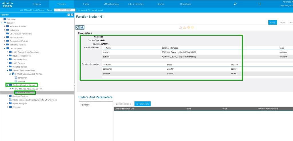
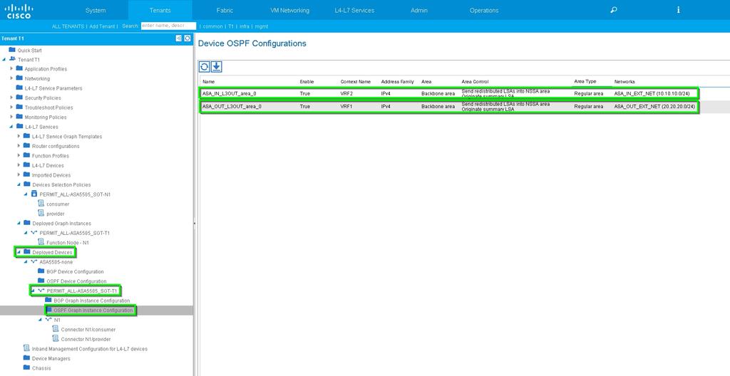
12 Step 7: Route-tag Policy, configure Route-tag Policy for VRF1 (Tag:100), as shown in the image: Configure Route-tag Policy for VRF2 (Tag:200), as shown in the image: Step 8: Check the status and verify Device Selection Policy, as shown in the image: Verify Deployed Graph instance, as shown in the image:
13
14 Verify and Troubleshoot APIC configuration for Tenant: apic1# sh running-config tenant T1 # Command: show running-config tenant T1 # Time: Thu Feb 25 16:05: tenant T1 access-list PERMIT_ALL match ip contract PERMIT_ALL scope tenant subject PERMIT_ALL access-group PERMIT_ALL both l4l7 graph ASA5585_SGT vrf context VRF1 vrf context VRF2 l3out ASA_IN_L3OUT vrf member VRF2 l3out ASA_OUT_L3OUT vrf member VRF1 l3out N3K-1_L3OUT vrf member VRF1 l3out N3K-2_L3OUT vrf member VRF2 bridge-domain BD1 vrf member VRF1 bridge-domain BD2 vrf member VRF2 application AP1 epg EPG1 bridge-domain member BD1 epg EPG2 bridge-domain member BD2 external-l3 epg ASA_IN_EXT_NET l3out ASA_IN_L3OUT vrf member VRF2 match ip /24 external-l3 epg ASA_OUT_EXT_NET l3out ASA_OUT_L3OUT vrf member VRF1 match ip /24 external-l3 epg N3K-1_EXT_NET l3out N3K-1_L3OUT vrf member VRF1 match ip /24 contract consumer PERMIT_ALL external-l3 epg N3K-2_EXT_NET l3out N3K-2_L3OUT
15 vrf member VRF2 match ip /24 contract provider PERMIT_ALL interface bridge-domain BD1 interface bridge-domain BD2 l4l7 cluster name ASA5585 type physical vlan-domain T1_PHY service FW function go-to cluster-device ASA5585_Device_1 cluster-interface inside member device ASA5585_Device_1 device-interface GigabitEthernet0/1 interface ethernet 1/2 leaf 106 cluster-interface outside member device ASA5585_Device_1 device-interface GigabitEthernet0/0 interface ethernet 1/2 leaf 105 l4l7 graph ASA5585_SGT contract PERMIT_ALL service N1 device-cluster-tenant T1 device-cluster ASA5585 mode FW_ROUTED connector consumer cluster-interface outside l4l7-peer tenant T1 out ASA_OUT_L3OUT epg ASA_OUT_EXT_NET redistribute bgp,ospf connector provider cluster-interface inside l4l7-peer tenant T1 out ASA_IN_L3OUT epg ASA_IN_EXT_NET redistribute bgp,ospf rtr-cfg ASA5585 connection C1 terminal consumer service N1 connector consumer connection C2 terminal provider service N1 connector provider rtr-cfg ASA5585 router-id apic1# Verify OSPF neighbor relationship and routing table on leaf 101: leaf101# show ip ospf neighbors vrf T1:VRF1 OSPF Process ID default VRF T1:VRF1 Total number of neighbors: 2 Neighbor ID Pri State Up Time Address Interface FULL/BDR 02:07: Vlan FULL/BDR 00:38: Vlan9 leaf101# show ip route vrf T1:VRF1 IP Route Table for VRF "T1:VRF1" '*' denotes best ucast next-hop '**' denotes best mcast next-hop '[x/y]' denotes [preference/metric] '%<string>' in via output denotes VRF <string> /24, ubest/mbest: 1/0 *via , vlan8, [110/8], 01:59:50, ospf-default, intra /24, ubest/mbest: 1/0 *via , vlan9, [110/22], 00:30:20, ospf-default, inter /32, ubest/mbest: 2/0, attached, direct *via , lo1, [1/0], 02:21:22, local, local *via , lo1, [1/0], 02:21:22, direct
16 /30, ubest/mbest: 1/0, attached, direct *via , vlan8, [1/0], 02:35:53, direct /32, ubest/mbest: 1/0, attached *via , vlan8, [1/0], 02:35:53, local, local /30, ubest/mbest: 1/0, attached, direct *via , vlan9, [1/0], 02:20:53, direct /32, ubest/mbest: 1/0, attached *via , vlan9, [1/0], 02:20:53, local, local /30, ubest/mbest: 1/0 *via , vlan9, [110/14], 00:30:20, ospf-default, intra /32, ubest/mbest: 1/0 *via , vlan9, [110/15], 00:30:20, ospf-default, intra Verify OSPF neighbor relationship and routing table on leaf 102: leaf102# show ip ospf neighbors vrf T1:VRF2 OSPF Process ID default VRF T1:VRF2 Total number of neighbors: 2 Neighbor ID Pri State Up Time Address Interface FULL/BDR 00:37: Vlan FULL/BDR 02:09: Vlan15 leaf102# show ip route vrf T1:VRF2 IP Route Table for VRF "T1:VRF2" '*' denotes best ucast next-hop '**' denotes best mcast next-hop '[x/y]' denotes [preference/metric] '%<string>' in via output denotes VRF <string> /24, ubest/mbest: 1/0 *via , vlan14, [110/22], 00:35:22, ospf-default, inter /24, ubest/mbest: 1/0 *via , vlan15, [110/8], 02:08:13, ospf-default, intra /30, ubest/mbest: 1/0 *via , vlan14, [110/14], 00:35:22, ospf-default, intra /30, ubest/mbest: 1/0, attached, direct *via , vlan14, [1/0], 02:14:29, direct /32, ubest/mbest: 1/0, attached *via , vlan14, [1/0], 02:14:29, local, local /30, ubest/mbest: 1/0, attached, direct *via , vlan15, [1/0], 02:09:04, direct /32, ubest/mbest: 1/0, attached *via , vlan15, [1/0], 02:09:04, local, local /32, ubest/mbest: 2/0, attached, direct *via , lo4, [1/0], 02:10:02, local, local *via , lo4, [1/0], 02:10:02, direct Verify configuration, OSPF neighbor relationship and routing table on ASA 5585: ASA5585# sh run interface! interface GigabitEthernet0/0 no nameif security-level 0 no ip address! interface GigabitEthernet0/0.101 nameif externalif security-level 50 ip address ! interface GigabitEthernet0/1 no nameif security-level 100
17 no ip address! interface GigabitEthernet0/1.102 nameif internalif security-level 100 ip address ! interface Management0/0 management-only nameif management security-level 0 ip address ASA5585# sh run router router ospf 1 router-id network area 0 network area 0 area 0 log-adj-changes! ASA5585# sh ospf neighbor Neighbor ID Pri State Dead Time Address Interface FULL/DR 0:00: externalif FULL/DR 0:00: internalif ASA5585# sh route ospf Routing Table: T1 Codes: L - local, C - connected, S - static, R - RIP, M - mobile, B - BGP D - EIGRP, EX - EIGRP external, O - OSPF, IA - OSPF inter area N1 - OSPF NSSA external type 1, N2 - OSPF NSSA external type 2 E1 - OSPF external type 1, E2 - OSPF external type 2 i - IS-IS, su - IS-IS summary, L1 - IS-IS level-1, L2 - IS-IS level-2 ia - IS-IS inter area, * - candidate default, U - per-user static route o - ODR, P - periodic downloaded static route, + - replicated route Gateway of last resort is not set O IA [110/18] via , 00:22:57, externalif O IA [110/18] via , 00:22:47, internalif O [110/11] via , 00:22:47, internalif ASA5585# sh access-list access-list cached ACL log flows: total 0, denied 0 (deny-flow-max 4096) alert-interval 300 access-list access-list-inbound; 3 elements; name hash: 0xcb5bd6c7 access-list access-list-inbound line 1 extended permit tcp any any eq www (hitcnt=0) 0xc873a747 access-list access-list-inbound line 2 extended permit tcp any any eq https (hitcnt=0) 0x48bedbdd access-list access-list-inbound line 3 extended permit icmp any any (hitcnt=6) 0xe4b5a75d Verify configuration, OSPF neighbor relationship and routing table on N3K-1
18 N3K-1# sh run ospf!command: show running-config ospf!time: Thu Feb 25 15:40: version 6.0(2)U3(7) feature ospf router ospf 1 router-id interface Ethernet1/21 ip router ospf 1 area interface Ethernet1/47 ip router ospf 1 area N3K-1# sh ip ospf neighbors OSPF Process ID 1 VRF default Total number of neighbors: 1 Neighbor ID Pri State Up Time Address Interface FULL/DR 01:36: Eth1/47 N3K-1# sh ip ospf route OSPF Process ID 1 VRF default, Routing Table (D) denotes route is directly attached /24 (intra)(d) area via /Eth1/21*, cost /24 (inter)(r) area via /Eth1/47, cost /32 (intra)(r) area via /Eth1/47, cost /30 (intra)(d) area via /Eth1/47*, cost 40 (R) denotes route is in RIB Verify configuration, OSPF neighbor relationship and routing table on N3K-2 N3K-2# sh run ospf!command: show running-config ospf!time: Thu Feb 25 15:44: version 6.0(2)U3(7) feature ospf router ospf 1 router-id interface loopback0 ip ospf network point-to-point ip router ospf 1 area interface Ethernet1/21 ip router ospf 1 area interface Ethernet1/47 ip router ospf 1 area N3K-2# sh ip ospf neighbors OSPF Process ID 1 VRF default
19 Total number of neighbors: 1 Neighbor ID Pri State Up Time Address Interface FULL/DR 01:43: Eth1/47 N3K-2# sh ip ospf route OSPF Process ID 1 VRF default, Routing Table (D) denotes route is directly attached /30 (intra)(d) area via /Lo0*, cost /24 (inter)(r) area via /Eth1/47, cost /24 (intra)(d) area via /Eth1/21*, cost /30 (intra)(d) area via /Eth1/47*, cost 40 (R) denotes route is in RIB Verify contract filter rules on leaf and the packet hit counts:. leaf101# show system internal policy-mgr stats Requested Rule Statistics [CUT] Rule (4107) DN (sys/actrl/scope /rule s d f-33) Ingress: 1316, Egress: 0, Pkts: 0 RevPkts: 0 Rule (4108) DN (sys/actrl/scope /rule s d f-33) Ingress: 1317, Egress: 0, Pkts: 0 RevPkts: 0 leaf101# show system internal policy-mgr stats Requested Rule Statistics [CUT] Rule (4107) DN (sys/actrl/scope /rule s d f-33) Ingress: 2317, Egress: 0, Pkts: 0 RevPkts: 0 Rule (4108) DN (sys/actrl/scope /rule s d f-33) Ingress: 2317, Egress: 0, Pkts: 0 RevPkts: 0 leaf102# show system internal policy-mgr stats Requested Rule Statistics [CUT] Rule (4103) DN (sys/actrl/scope /rule s d-6019-f-default) Ingress: 3394, Egress: 0, Pkts: 0 RevPkts: 0 Rule (4104) DN (sys/actrl/scope /rule s-6019-d f-default) Ingress: 3394, Egress: 0, Pkts: 0 RevPkts: 0 [CUT] leaf102# show system internal policy-mgr stats Requested Rule Statistics [CUT] Rule (4103) DN (sys/actrl/scope /rule s d-6019-f-default) Ingress: 4392, Egress: 0, Pkts: 0 RevPkts: 0 Rule (4104) DN (sys/actrl/scope /rule s-6019-d f-default) Ingress: 4392, Egress: 0, Pkts: 0 RevPkts: 0 [CUT] Reachability test between N3K-1 and N3K-2: N3K-1# ping source PING ( ) from : 56 data bytes 64 bytes from : icmp_seq=0 ttl=250 time=2.098 ms 64 bytes from : icmp_seq=1 ttl=250 time=0.922 ms 64 bytes from : icmp_seq=2 ttl=250 time=0.926 ms 64 bytes from : icmp_seq=3 ttl=250 time=0.893 ms 64 bytes from : icmp_seq=4 ttl=250 time=0.941 ms ping statistics packets transmitted, 5 packets received, 0.00% packet loss round-trip min/avg/max = 0.893/1.156/2.098 ms N3K-2# ping source PING ( ) from : 56 data bytes
20 64 bytes from : icmp_seq=0 ttl=250 time=2.075 ms 64 bytes from : icmp_seq=1 ttl=250 time=0.915 ms 64 bytes from : icmp_seq=2 ttl=250 time=0.888 ms 64 bytes from : icmp_seq=3 ttl=250 time=1.747 ms 64 bytes from : icmp_seq=4 ttl=250 time=0.828 ms ping statistics packets transmitted, 5 packets received, 0.00% packet loss round-trip min/avg/max = 0.828/1.29/2.075 ms Attached is the XML configuration file for the Tenant and the ASA Function Profile, used for this demonstration.
Layer 4 to Layer 7 Design
 Service Graphs and Layer 4 to Layer 7 Services Integration, page 1 Firewall Service Graphs, page 5 Service Node Failover, page 10 Service Graphs with Multiple Consumers and Providers, page 12 Reusing a
Easy Virtual Network Configuration Example
 Easy Virtual Network Configuration Example Document ID: 117974 Contributed by Fabrice Ducomble, Cisco TAC Engineer. Aug 04, 2014 Contents Introduction Prerequisites Requirements Components Used Background
Routing Design. Transit Routing. About Transit Routing
 Transit Routing, page 1 L3Out Ingress Policy Enforcement, page 16 L3Out MTU Considerations, page 20 Shared L3Outs, page 22 L3Out Router IDs, page 27 Multiple External Connectivity, page 30 Transit Routing
ASA Has High CPU Usage Due to a Traffic Loop When VPN Clients Disconnect
 ASA Has High CPU Usage Due to a Traffic Loop When VPN Clients Disconnect Contents Introduction Prerequisites Requirements Components Used Background Information Problem: Packets Destined for a Disconnected
Configuring Policy-Based Redirect
 About Policy-Based Redirect, page 1 About Symmetric Policy-Based Redirect, page 8 Policy Based Redirect and Hashing Algorithms, page 8 Using the GUI, page 9 Using the NX-OS-Style CLI, page 10 Verifying
Configuring Policy-Based Redirect
 About Policy-Based Redirect, on page 1 About Multi-Node Policy-Based Redirect, on page 3 About Symmetric Policy-Based Redirect, on page 3 Policy Based Redirect and Hashing Algorithms, on page 4 Policy-Based
Routing Implementation
 L3Out Subnets, page 1 L3Out Subnets About Defining L3Out Subnets L3Outs are the Cisco Application Centric Infrastructure (ACI) objects used to provide external connectivity in external Layer 3 networks.
GRE Tunnel with VRF Configuration Example
 GRE Tunnel with VRF Configuration Example Document ID: 46252 Contents Introduction Prerequisites Requirements Components Used Conventions Configure Network Diagram Configurations Verify Troubleshoot Caveats
Use Case: Three-Tier Application with Transit Topology
 Use Case: Three-Tier Application with Transit Topology About Deploying a Three-Tier Application with Transit Topology, on page 1 Deploying a Three-Tier Application, on page 3 Transit Routing with OSPF
Configuring Policy-Based Redirect
 About Policy-Based Redirect, page 1 About Symmetric Policy-Based Redirect, page 8 Using the GUI, page 8 Using the NX-OS-Style CLI, page 10 Verifying a Policy-Based Redirect Configuration Using the NX-OS-Style
CCNA Exploration: Routing Protocols and Concepts Chapter 10 Case Study
 Objectives: Use OSPF single area to illustrate basic Link State components and operation. Migrate from EIGRP to OSPF single area. Intro: Trevni Inc. decided to upgrade their routing protocol from EIGRP
Contents. Introduction. Prerequisites. Requirements. Components Used
 Contents Introduction Prerequisites Requirements Components Used Configure Network Diagram Configurations OSPF EIGRP RIP Troubleshoot Introduction This document describes how to redistribute Internal Border
vpc Layer 3 Backup Routing with F1 and Peer Gateway
 vpc Layer 3 Backup Routing with F1 and Peer Gateway Document ID: 116740 Contributed by Andy Gossett, Cisco TAC Engineer. Dec 16, 2013 Contents Introduction Prerequisites Requirements Components Used Configure
Multi-Site Use Cases. Cisco ACI Multi-Site Service Integration. Supported Use Cases. East-West Intra-VRF/Non-Shared Service
 Cisco ACI Multi-Site Service Integration, on page 1 Cisco ACI Multi-Site Back-to-Back Spine Connectivity Across Sites Without IPN, on page 8 Bridge Domain with Layer 2 Broadcast Extension, on page 9 Bridge
Adjust Administrative Distance for Route Selection in Cisco IOS Routers Configuration Example
 Adjust Administrative Distance for Route Selection in Cisco IOS Routers Configuration Example Document ID: 113153 Contents Introduction Prerequisites Requirements Components Used Conventions Configure
Configuring Redundant Routing on the VPN 3000 Concentrator
 Configuring Redundant Routing on the VPN 3000 Concentrator Document ID: 13354 Contents Introduction Prerequisites Requirements Components Used Conventions Configure Network Diagram Router Configurations
Contents. Introduction. Prerequisites. Requirements
 Contents Introduction Prerequisites Requirements Components Used Configure Network Diagram Configurations Verify Inheritence with EIGRP Named mode Route Replication with EIGRP name mode Routing Context
DHCP Relay in VXLAN BGP EVPN
 Overview, on page 1 Guidelines and Limitations for DHCP Relay, on page 2 Example, on page 2 Configuring VPC Peers Example, on page 19 vpc VTEP DHCP Relay Configuration Example, on page 21 Overview DHCP
DHCP Relay in VXLAN BGP EVPN
 Overview, page 1 Example, page 2 Configuring VPC Peers Example, page 16 vpc VTEP DHCP Relay Configuration Example, page 18 Overview DHCP relay is supported by VXLAN BGP EVPN and is useful in a multi-tenant
Deploy Application Load Balancers with Source Network Address Translation in Cisco DFA
 White Paper Deploy Application Load Balancers with Source Network Address Translation in Cisco DFA Last Updated: 1/27/2016 2016 Cisco and/or its affiliates. All rights reserved. This document is Cisco
Deploying ASA. ASA Deployment Modes in ACI Fabric
 ASA Deployment Modes in ACI Fabric, page 1 About the ASA Operational Model, page 2 Translation of ASA Terminology, page 2 About ASA Multi-Context Mode, page 3 About ASA High Availability and Scalability,
Service Graph Design with Cisco Application Centric Infrastructure
 White Paper Service Graph Design with Cisco Application Centric Infrastructure 2017 Cisco and/or its affiliates. All rights reserved. This document is Cisco Public Information. Page 1 of 101 Contents Introduction...
Chapter 7 Lab 7-1, Configuring BGP with Default Routing
 Chapter 7 Topology Objectives Configure BGP to exchange routing information with two ISPs. Background The International Travel Agency (ITA) relies extensively on the Internet for sales. For this reason,
Cisco ACI Multi-Pod and Service Node Integration
 White Paper Cisco ACI Multi-Pod and Service Node Integration 2018 Cisco and/or its affiliates. All rights reserved. This document is Cisco Public Information. Page 1 of 68 Contents Introduction... 3 Prerequisites...
Schema Management. Schema Management
 , page 1 Creating a Schema Template, page 2 Configuring an Application Profile, page 2 Configuring a Contract, page 3 Configuring a Bridge Domain, page 4 Configuring a VRF for the Tenant, page 4 Configuring
ACI Transit Routing, Route Peering, and EIGRP Support
 ACI Transit Routing, Route Peering, and EIGRP Support ACI Transit Routing This chapter contains the following sections: ACI Transit Routing, on page 1 Transit Routing Use Cases, on page 1 ACI Fabric Route
Layer3 VPN with OSPF Protocol between CE-PE
 MPLS Layer3 VPN with OSPF Protocol between CE-PE Disclaimer This Configuration Guide is designed to assist members to enhance their skills in particular technology area. While every effort has been made
LAB1: BGP IPv4. BGP: Initial Config. Disclaimer
 Page1 LAB1: BGP IPv4 Disclaimer This Configuration Guide is designed to assist members to enhance their skills in respective technology area. While every effort has been made to ensure that all material
Deploying LISP Host Mobility with an Extended Subnet
 CHAPTER 4 Deploying LISP Host Mobility with an Extended Subnet Figure 4-1 shows the Enterprise datacenter deployment topology where the 10.17.1.0/24 subnet in VLAN 1301 is extended between the West and
ACI Fabric Endpoint Learning
 White Paper ACI Fabric Endpoint Learning 2018 Cisco and/or its affiliates. All rights reserved. This document is Cisco Public Information. Page 1 of 45 Contents Introduction... 3 Goals of this document...
LAB5: OSPF IPv4. OSPF: Stub. Disclaimer
 Page1 LAB5: SPF IPv4 Disclaimer This onfiguration Guide is designed to assist members to enhance their skills in respective technology area. While every effort has been made to ensure that all material
Configuration and Management of Networks
 Configuring BGP using the AS_PATH attribute Topology Objectives Background Use BGP commands to prevent private AS numbers from being advertised to the outside world. Use the AS_PATH attribute to filter
Configuring Easy Virtual Network Shared Services
 Configuring Easy Virtual Network Shared Services This chapter describes how to use route replication and redistribution to share services in an Easy Virtual Network (EVN). Finding Feature Information,
Cisco UCS Director Tech Module Cisco Application Centric Infrastructure (ACI)
") Cisco UCS Director Tech Module Cisco Application Centric Infrastructure (ACI) Version: 1.0 September 2016 1 Agenda Overview & Architecture Hardware & Software Compatibility Licensing Orchestration Capabilities
Cisco UCS Director Tech Module Cisco Application Centric Infrastructure (ACI) Version: 1.0 September 2016 1 Agenda Overview & Architecture Hardware & Software Compatibility Licensing Orchestration Capabilities
Chapter 7 Lab 7-2, Using the AS_PATH Attribute
 Chapter 7 Topology Objectives Use BGP commands to prevent private AS numbers from being advertised to the outside world. Use the AS_PATH attribute to filter BGP routes based on their source AS numbers.
Configuring APIC Accounts
 This chapter contains the following sections: Adding an APIC Account, page 1 Viewing APIC Reports, page 3 Assigning an APIC account to a Pod, page 15 Handling APIC Failover, page 15 Adding an APIC Account
Initial Configurations for OSPF over a Point to Point Link
 Initial onfigurations for OSPF over a Point to Point Link Document ID: 13687 ontents Introduction Prerequisites Requirements omponents Used onventions OSPF over a Point to Point Link with IP Addresses
LAB11: EIGRP IPv4. EIGRP: Stub. Disclaimer
 Page1 AB11: EIGRP IPv4 isclaimer This onfiguration Guide is designed to assist members to enhance their skills in respective technology area. While every effort has been made to ensure that all material
Modeling an Application with Cisco ACI Multi-Site Policy Manager
 Modeling an Application with Cisco ACI Multi-Site Policy Manager Introduction Cisco Application Centric Infrastructure (Cisco ACI ) Multi-Site is the policy manager component used to define intersite policies
OSPF. About OSPF. CLI Book 1: Cisco ASA Series General Operations CLI Configuration Guide, 9.4 1
 This chapter describes how to configure the Cisco ASA to route data, perform authentication, and redistribute routing information using the Open Shortest Path First () routing protocol. About, page 1 Guidelines
RealCiscoLAB.com. Chapter 6 Lab 6-2, Using the AS_PATH Attribute. Topology. Objectives. Background. CCNPv6 ROUTE
 RealCiscoLAB.com CCNPv6 ROUTE Chapter 6 Lab 6-2, Using the AS_PATH Attribute Topology Objectives Background Use BGP commands to prevent private AS numbers from being advertised to the outside world. Use
Adapted from the Synchronization example in g/case/studies/icsbgp4.html
 Adapted from the Synchronization example in http://www.cisco.com/en/us/docs/internetworkin g/case/studies/icsbgp4.html When an AS provides transit service to other ASs when there are non-bgp routers in
ASA 9.x EIGRP Configuration Example
 ASA 9.x EIGRP Configuration Example Contents Introduction Prerequisites Requirements Components Used Background Information Guidelines and Limitations EIGRP and Failover Configure Network Diagram ASDM
Verified Scalability Guide for Cisco APIC, Release 3.0(1k) and Cisco Nexus 9000 Series ACI-Mode Switches, Release 13.0(1k)
 and Cisco Nexus 9000 Series ACI-Mode Switches, Release 13.0(1k)") Verified Scalability Guide for Cisco APIC, Release 3.0(1k) and Cisco Nexus 9000 Series ACI-Mode Switches, Release 13.0(1k) Overview 2 General Scalability Limits 2 Fabric Topology, SPAN, Tenants, Contexts
Verified Scalability Guide for Cisco APIC, Release 3.0(1k) and Cisco Nexus 9000 Series ACI-Mode Switches, Release 13.0(1k) Overview 2 General Scalability Limits 2 Fabric Topology, SPAN, Tenants, Contexts
Multihoming with BGP and NAT
 Eliminating ISP as a single point of failure www.noction.com Table of Contents Introduction 1. R-NAT Configuration 1.1 NAT Configuration 5. ISPs Routers Configuration 3 15 7 7 5.1 ISP-A Configuration 5.2
Chapter 1 Lab 1-1, Basic RIPng and Default Gateway Configuration
 Chapter 1 Lab 1-1, Basic RIPng and Default Gateway Configuration Topology Objectives Configure IPv6 addressing. Configure and verify RIPng on R1 and R2. Configure IPv6 static routes between R2 and R3.
FlexVPN HA Dual Hub Configuration Example
 FlexVPN HA Dual Hub Configuration Example Document ID: 118888 Contributed by Piotr Kupisiewicz, Wen Zhang, and Frederic Detienne, Cisco TAC Engineers. Apr 08, 2015 Contents Introduction Prerequisites Requirements
Configuring Layer 4 to Layer 7 Resource Pools
 Configuring Layer 4 to Layer 7 Resource Pools About Layer 4 to Layer 7 Resource Pools, page 1 About External IP Address Pools, page 2 About External Layer 3 Routed Domains and the Associated VLAN Pools,
Lab- Configuring Basic Single-Area OSPFv2
 Lab- onfiguring Basic Single-Area OSPFv2 Topology G0/0 G0/0 2013 isco and/or its affiliates. All rights reserved. This document is isco Public. Page 1 of 29 Addressing Table Objectives Device Interface
Verified Scalability Guide for Cisco APIC, Release 3.0(1k) and Cisco Nexus 9000 Series ACI-Mode Switches, Release 13.0(1k)
 and Cisco Nexus 9000 Series ACI-Mode Switches, Release 13.0(1k)") Verified Scalability Guide for Cisco APIC, Release 3.0(1k) and Cisco Nexus 9000 Series ACI-Mode Switches, Release 13.0(1k) Overview 2 General Scalability Limits 2 Fabric Topology, SPAN, Tenants, Contexts
Verified Scalability Guide for Cisco APIC, Release 3.0(1k) and Cisco Nexus 9000 Series ACI-Mode Switches, Release 13.0(1k) Overview 2 General Scalability Limits 2 Fabric Topology, SPAN, Tenants, Contexts
Layer 4 to Layer 7 Service Insertion, page 1
 This chapter contains the following sections:, page 1 Layer 4 to Layer 7 Policy Model, page 2 About Service Graphs, page 2 About Policy-Based Redirect, page 5 Automated Service Insertion, page 12 About
Cisco ACI Multi-Pod/Multi-Site Deployment Options Max Ardica Principal Engineer BRKACI-2003
 Cisco ACI Multi-Pod/Multi-Site Deployment Options Max Ardica Principal Engineer BRKACI-2003 Agenda ACI Introduction and Multi-Fabric Use Cases ACI Multi-Fabric Design Options ACI Stretched Fabric Overview
Lab 6-1 Configuring a WLAN Controller
 Lab 6-1 Configuring a WLAN Controller Topology Diagram Scenario Step 1 In the next two labs, you will configure a wireless solution involving a WLAN controller, two lightweight wireless access points,
Configuring the Catena Solution
 This chapter describes how to configure Catena on a Cisco NX-OS device. This chapter includes the following sections: About the Catena Solution, page 1 Licensing Requirements for Catena, page 2 Guidelines
New and Changed Information
 This chapter contains the following sections:, page 1 The following table provides an overview of the significant changes to this guide for this current release. The table does not provide an exhaustive
Network Layer Week 5. Module : Computer Networks Lecturer: Lucy White Office : 324
 Network Layer Week 5 Module : Computer Networks Lecturer: Lucy White lbwhite@wit.ie Office : 324 1 Network Layer Network Layer Protocols Common Network Layer Protocols Internet Protocol version 4 (IPv4)
MPLS VPN Half-Duplex VRF
 The feature provides scalable hub-and-spoke connectivity for subscribers of an Multiprotocol Label Switching (MPLS) Virtual Private Network (VPN) service. This feature addresses the limitations of hub-and-spoke
Routing Overview. Path Determination
 This chapter describes underlying concepts of how routing behaves within the Cisco ASA, and the routing protocols that are supported. Routing is the act of moving information across a network from a source
ACI Terminology. This chapter contains the following sections: ACI Terminology, on page 1. Cisco ACI Term. (Approximation)
") This chapter contains the following sections:, on page 1 Alias API Inspector App Center Alias A changeable name for a given object. While the name of an object, once created, cannot be changed, the Alias
This chapter contains the following sections:, on page 1 Alias API Inspector App Center Alias A changeable name for a given object. While the name of an object, once created, cannot be changed, the Alias
Nexus 9000/3000 Graceful Insertion and Removal (GIR)
") White Paper Nexus 9000/3000 Graceful Insertion and Removal (GIR) White Paper September 2016 2016 Cisco and/or its affiliates. All rights reserved. This document is Cisco Public Information. Page 1 of 21
White Paper Nexus 9000/3000 Graceful Insertion and Removal (GIR) White Paper September 2016 2016 Cisco and/or its affiliates. All rights reserved. This document is Cisco Public Information. Page 1 of 21
RealCiscoLAB.com. Chapter 2 Lab 2-2, EIGRP Load Balancing. Topology. Objectives. Background. CCNPv6 ROUTE
 RealCiscoLAB.com CCNPv6 ROUTE Chapter 2 Lab 2-2, EIGRP Load Balancing Topology Objectives Background Review a basic EIGRP configuration. Explore the EIGRP topology table. Identify successors, feasible
Abstract. Avaya Solution & Interoperability Test Lab
 Avaya Solution & Interoperability Test Lab Configuring VPN backup for Avaya S8700 Media Servers and Avaya G600 Media Gateways Controlling Avaya G350 Media Gateways, using the Avaya Security Gateway and
How to Configure a Cisco Router Behind a Non-Cisco Cable Modem
 How to Configure a Cisco Router Behind a Non-Cisco Cable Modem Document ID: 19268 Contents Introduction Prerequisites Requirements Components Used Conventions Configure Network Diagram Configurations Verify
Cisco Interconnecting Cisco Networking Devices Part 2
 Cisco 200-105 Interconnecting Cisco Networking Devices Part 2 R1# show running-config description ***Loopback*** ip address 192.168.1.1 255.255.255.255 Question: 374 description **Connected to R1-LAN**
Implement Static Routes for IPv6 Configuration Example
 Implement Static Routes for IPv6 Configuration Example Document ID: 113361 Contents Introduction Prerequisites Components Used Conventions Configure Network Diagram Configurations Verify Related Information
LAB8: OSPF IPv4. OSPF: Virtual Link. Disclaimer
 Page1 AB8: OSPF IPv4 Disclaimer This onfiguration Guide is designed to assist members to enhance their skills in respective technology area. While every effort has been made to ensure that all material
Lab b Simple DMZ Extended Access Lists Instructor Version 2500
 Lab 11.2.3b Simple DMZ Extended Access Lists Instructor Version 2500 Objective In this lab, the use of extended access lists to create a simple DeMilitarized Zone (DMZ) will be learned. 372-833 CCNA 2:
Configuring Network Access to the GGSN
 CHAPTER 7 This chapter describes how to configure access from the gateway GPRS support node (GGSN) to a serving GPRS support node (SGSN), public data network (PDN), and optionally to a Virtual Private
Case Study 2: Frame Relay and OSPF Solution
 Case Study 2: Frame Relay and OSPF Solution Objective In this case study, you troubleshoot a complex scenario involving Frame Relay and Open Shortest Path First (OSPF). Figure 2-1 shows the topology for
LAB8: Named EIGRP IPv4
 Page1 AB8: Named EIGRP IPv4 isclaimer This onfiguration Guide is designed to assist members to enhance their skills in respective technology area. While every effort has been made to ensure that all material
Information About Routing
 19 CHAPTER This chapter describes underlying concepts of how routing behaves within the adaptive security appliance, and the routing protocols that are supported. The chapter includes the following sections:,
Page 2
 Page 2 Mgmt-B, vmotion-a vmotion-b VMM-Pool-B_ Connection-B -Set-A Uplink-Set-A Uplink-Set-B ACI-DC Standard Aggregation L3 Switch Configuration for existing Layer 2 : Nexus 6K-01 switch is
Lab 6-1 Configuring a WLAN Controller
 Lab 6-1 Configuring a WLAN Controller Topology Diagram Scenario In the next two labs, you will configure a wireless solution involving a WLAN controller, two lightweight wireless access points, and a switched
I Commands. iping, page 2 iping6, page 4 itraceroute, page 5 itraceroute6 vrf, page 6. itraceroute vrf encap vxlan, page 12
 iping, page 2 iping6, page 4 itraceroute, page 5 itraceroute6 vrf, page 6 itraceroute6 vrf encap vlan, page 7 itraceroute6 vrf encap vxlan dst-mac, page 8 itraceroute vrf, page 9 itraceroute vrf encap
Segment Routing on Cisco Nexus 9500, 9300, 9200, 3200, and 3100 Platform Switches
 White Paper Segment Routing on Cisco Nexus 9500, 9300, 9200, 3200, and 3100 Platform Switches Authors Ambrish Mehta, Cisco Systems Inc. Haider Salman, Cisco Systems Inc. 2017 Cisco and/or its affiliates.
INTERNET TEACHING LAB: Interior Gateway Protocol (IGP) LAB
 LAB") INTERNET TEACHING LAB: Interior Gateway Protocol (IGP) LAB Overview In this lab, we will explore some common interior gateway protocols - RIP version 1 (Routing Information Protocol) - OSPF (Open Shortest
INTERNET TEACHING LAB: Interior Gateway Protocol (IGP) LAB Overview In this lab, we will explore some common interior gateway protocols - RIP version 1 (Routing Information Protocol) - OSPF (Open Shortest
MPLS VPN C H A P T E R S U P P L E M E N T. BGP Advertising IPv4 Prefixes with a Label
 7 C H A P T E R S U P P L E M E N T This online supplement of Chapter 7 focuses on two important developments. The first one is Inter-Autonomous. Inter-Autonomous is a concept whereby two service provider
CCIE R&S Techtorial MPLS
 CCIE R&S Techtorial MPLS Ing. Tomáš Kelemen Partner Systems Engineer CCIE #24395 Ing. Peter Mesjar Systems Engineer CCIE #17428 2011 Cisco Systems, Inc. All rights reserved. 1 Agenda Introduction to MPLS
Failover with EIGRP Using VRF Configuration Example
 Failover with EIGRP Using VRF onfiguration Example ocument I: 113446 ontents Introduction Prerequisites Hardware and Software Versions onventions onfigure Network iagram onfigurations Verify Show ommands
Chapter 4 Lab 4-2, Controlling Routing Updates. Topology. Objectives. CCNPv7 ROUTE
 Chapter 4 Lab 4-2, Controlling Routing Updates Topology Objectives Filter routes using a distribute list and ACL. Filter routes using a distribute list and prefix list. Filter redistributed routes using
Lab- Troubleshooting Basic EIGRP for 1Pv4
 Lab- Troubleshooting Basic EIGRP for 1Pv4 Topology G0/0 G0/0 PC-A PC-C 2013 Cisco and/or its affiliates. All rights reserved. This document is Cisco Public. Page 1 of 27 Addressing Table efault Gateway
Troubleshooting LSP Failure in MPLS VPN
 Troubleshooting LSP Failure in MPLS VPN Document ID: 23565 Contents Introduction Prerequisites Requirements Components Used Conventions Network Diagram Router Configurations Problem Cause of the LSP Failure
Lab VTY Restriction Instructor Version 2500
 Lab 11.2.6 VTY Restriction Instructor Version 2500 NOTE: The loopback entry in this graphic is not required in the lab. Objective Scenario Use the access-class and line commands to control Telnet access
Cisco ACI Terminology ACI Terminology 2
 inology ACI Terminology 2 Revised: May 24, 2018, ACI Terminology Cisco ACI Term Alias API Inspector App Center Application Policy Infrastructure Controller (APIC) Application Profile Atomic Counters Alias
Basic Router Configuration
 This section includes information about some basic router configuration, and contains the following sections: Default Configuration, on page 1 Configuring Global Parameters, on page 2 Configuring Gigabit
OSPF Commands. Cisco IOS IP Command Reference, Volume 2 of 3: Routing Protocols IP2R-61
 OSPF Commands Use the commands in this chapter to configure and monitor the Open Shortest Path First (OSPF) routing protocol. For OSPF configuration information and examples, refer to the Configuring OSPF
Working with Contracts
 Contracts, page 1 Filters, page 9 Taboo Contracts, page 12 Inter-Tenant Contracts, page 15 Contracts Contracts provide a way for the Cisco Application Centric Infrastructure (ACI) administrator to control
Routing Overview. Information About Routing CHAPTER
 21 CHAPTER This chapter describes underlying concepts of how routing behaves within the ASA, and the routing protocols that are supported. This chapter includes the following sections: Information About
Chapter 6 Lab 6-3, Configuring IBGP and EBGP Sessions, Local Preference, and MED
 Chapter 6 Lab 6-3, Configuring IBGP and EBGP Sessions, Local Preference, and MED Topology Objectives Background For IBGP peers to correctly exchange routing information, use the next-hop-self command with
Chapter 8 Lab 8-3, Configuring 6to4 Tunnels
 Chapter 8 Lab 8-3, Configuring 6to4 Tunnels Topology Objectives Configure EIGRP for IPv4. Create a 6to4 tunnel. Configure static IPv6 routes. Background In this lab, you configure EIGRP for full connectivity
OSPFv3 Route Filtering Using Distribute-List
 The OSPFv3 route filtering using distribute-list feature allows users to filter the incoming routes that are programmed in routing table, and the outgoing routes that are advertised. Finding Feature Information,
Shortcut Switching Enhancements for NHRP in DMVPN Networks
 Shortcut Switching Enhancements for NHRP in DMVPN Networks Routers in a Dynamic Multipoint VPN (DMVPN) Phase 3 network use Next Hop Resolution Protocol (NHRP) Shortcut Switching to discover shorter paths
Ch. 5 Maintaining and Troubleshooting Routing Solutions. Net412- Network troubleshooting
 Ch. 5 Maintaining and Troubleshooting Routing Solutions Net412- Network troubleshooting Troubleshooting Routing Network Layer Connectivity EIGRP OSPF 2 Network Connectivity Just like we did when we looked
Chapter 6 Lab 6-4, BGP Route Reflectors and Route Filters
 Chapter 6 Lab 6-4, BGP Route Reflectors and Route Filters Topology Objectives Background Configure IBGP routers to use a route reflector and a simple route filter. The International Travel Agency maintains
Chapter 4 Lab 4-3, Manipulating Administrative Distances
 hapter 4 Lab 4-3, Manipulating Administrative Distances Topology bjectives Background onfigure RIP on a router. onfigure SPF on a router. Manipulate administrative distances. ompare routing protocol behavior.
Chapter 3 Lab 3-2, Multi-Area OSPFv2 and OSPFv3 with Stub Area
 Chapter 3 Topology Objectives Configure multi-area OSPFv2 for IPv4. Configure multi-area OSPFv3 for IPv6 Verify multi-area behavior. Configure stub and totally stubby areas for OSPFv2. Configure stub and
CertifyMe. CertifyMe
 CertifyMe Number: 642-661 Passing Score: 800 Time Limit: 120 min File Version: 7.6 http://www.gratisexam.com/ CertifyMe-642-661 Exam A QUESTION 1 Exhibit: Certkiller router#show ip route Codes: C - connected,
IP NAT Troubleshooting. Solutions. Luke Bibby, CCIE #45527
 IP NAT Troubleshooting Solutions Luke Bibby, CCIE #45527 Quick Overview of Scenario Solutions Scenario #1 R2 s E0/0 should be NAT inside not NAT outside ACL 100 is configured incorrectly NAT policy missing
ACI Multi-Site Architecture and Deployment. Max Ardica Principal Engineer - INSBU
 ACI Multi-Site Architecture and Deployment Max Ardica Principal Engineer - INSBU Agenda ACI Network and Policy Domain Evolution ACI Multi-Site Deep Dive Overview and Use Cases Introducing ACI Multi-Site
Chapter 3 Lab 3-4, OSPF over Frame Relay
 Chapter 3 Lab 3-4, OSPF over Frame Relay Topology Objectives Background Configure OSPF over Frame Relay. Use non-broadcast and point-to-multipoint OSPF network types. Modify default OSPF timers. You are