COM600 Station Automation Series IEC Slave (OPC) 3.1. User's Guide
|
|
|
- Posy Bailey
- 5 years ago
- Views:
Transcription

1
2
3 Issued: Version: D/ Contents: 1. About this manual Copyrights Trademarks General Document conventions Terminology Abbreviations Related documents Document revisions Introduction Product overview IEC104 Slave PC Client features Configuration About this section verview of configuration Building object tree General about building object tree Adding IEC104 Slave PC Client Adding Channel objects Adding Device objects Adding data objects Configuring objects General about configuring objects Configuring IEC104 Slave PC Client properties Configuring IEC104 Channel Properties Configuring IEC104 Device properties Configuring Data objects General about configuring data objects Single point status (SPS) Double point status (DPS) Integer status (INS) Protection activation information (ACT) Directional protection activation information (ACD) Binary counter reading (BCR) easured value (V) Complex measured value (CV) WYE Delta (DEL) Controllable single point (SPC) Controllable double point (DPC) Controllable integer status (INC)
4 Binary controlled step position information (BSC) Integer controlled step position information (ISC) Analogue set point (APC) peration About this section Activating Gateway with new configurations IEC104 Slave PC Client diagnostics IEC104 Channel diagnostics IEC104 Device diagnostics Signal diagnostics Technical reference About this section IEC data modeling General about IEC data modeling Single point status (SPS) Double point status (DPS) Integer status (INS) Protection activation information (ACT) Directional protection activation information (ACD) Binary counter reading (BCR) easured value (V) Complex measured value (CV) WYE Delta (DEL) Controllable single point (SPC) Controllable double point (DPC) Controllable integer status (INC) Binary controlled step position information (BSC) Integer controlled step position information (ISC) Analogue set point (APC) Status codes Introduction Link layer status codes Application layer status codes Attributes General about attributes Client attributes Channel attributes Device attributes Appendix Interoperability list for IEC104 Slave PC Client
5 Index
6 6
7 1. About this manual 1.1. Copyrights The information in this document is subject to change without notice and should not be construed as a commitment by ABB y. ABB y assumes no responsibility for any errors that may appear in this document. In no event shall ABB y be liable for direct, indirect, special, incidental or consequential damages of any nature or kind arising from the use of this document, nor shall ABB y be liable for incidental or consequential damages arising from use of any software or hardware described in this document. This document and parts thereof must not be reproduced or copied without written permission from ABB y, and the contents thereof must not be imparted to a third party nor used for any unauthorized purpose. The software or hardware described in this document is furnished under a license and may be used, copied, or disclosed only in accordance with the terms of such license. Copyright 2006 ABB. All rights reserved Trademarks ABB is a registered trademark of ABB Group. All other brand or product names mentioned in this document may be trademarks or registered trademarks of their respective holders General This manual provides thorough information on the PC Client for Slave protocol (later in this manual IEC104 Slave PC Client) and the central concepts related to it. You will find instructions on to take it into use. The basic operation procedures are also discussed. Information in this user s guide is intended for application engineers who need to configure IEC104 Slave PC Client in order to establish communication to an PC server. As a prerequisite, you should understand protocol and the basic procedures in C600 Communication Engineering Tool (CET). This user s guide is divided into following sections: 7
8 Introduction This section gives an overview of the IEC104 Slave PC Client and states the system requirements to be met when using the client. Configuration In this section you will find an overview of the configuration tasks and instructions on how to create and configure IEC104 Slave PC Client related objects. peration This section covers the basic operation procedures you can carry out when transferring or activating the Communication Gateway C610 computer or Station Computer 615 with new configurations. You are also given instructions on how to monitor and control the IEC104 communication. Technical reference This section contains a list of status codes and information about the IEC data modelling Document conventions The following conventions are used for the presentation of material: The words in names of screen elements (for example, the title in the title bar of a window, the label for a field of a dialog box) are initially capitalized. Capital letters are used for the name of a keyboard key if it is labeled on the keyboard. For example, press the ENTER key. Lowercase letters are used for the name of a keyboard key that is not labeled on the keyboard. For example, the space bar, comma key, and so on. Press CTRL+C indicates that you must hold down the CTRL key while pressing the C key (to copy a selected object in this case). Press ESC E C indicates that you press and release each key in sequence (to copy a selected object in this case). The names of push and toggle buttons are boldfaced. For example, click K. The names of menus and menu items are boldfaced. For example, the File menu. The following convention is used for menu operations: enuname > enu- Item > CascadedenuItem. For example: select File > New > Type. The Start menu name always refers to the Start menu on the Windows taskbar. System prompts/messages and user responses/input are shown in the Courier font. For example, if you enter a value out of range, the following message is displayed: 8
9 Entered value is not valid. The value must be 0 to 30. You may be told to enter the string IF349 in a field. The string is shown as follows in the procedure: IF349 Variables are shown using lowercase letters: sequence name 1.5. Terminology The following is a list of terms associated with the IEC104 Slave PC Client that you should be familiar with. The list contains terms that are unique to ABB or have a usage or definition that is different from standard industry usage. Term Alarm Alarms and Events; AE Data Access; DA Data bject; D Data Set Device Event Intelligent Electronic Device Logical Device; LD Logical Node; LN LN LN Application Guideline for substation automation; LAG An abnormal state of a condition. An PC service for providing information about alarms and events to PC clients. An PC service for providing information about process data to PC clients. Part of a logical node object representing specific information, e.g., status or measurement. From an object-oriented point of view a data object is an instance of a class data object. Ds are normally used as transaction objects; i.e., they are data structures. The data set is the content basis for reporting and logging. The data set contains references to the data and data attribute values. A physical device that behaves as its own communication node in the network, e.g. protection relay. Change of process data or an PC internal value. Normally, an event consists of value, quality and timestamp. A physical IEC device that behaves as its own communication node in the IEC protocol. Representation of a group of functions. Each function is defined as a logical node. A physical device consists of one or several LDs. The smallest part of a function that exchanges data. A LN is an object defined by its data and methods. A communication protocol developed by Echelon. A proprietary method of ABB on top of the standard LN protocol. 9
10 Term PC PC item Property Report Control Block SPA SPA device Substation Configuration Language; SCL Series of standards specifications aiming at open connectivity in industrial automation and the enterprise systems that support industry. Representation of a connection to the data source within the PC server. An PC item is identified by a string <object path>:<property name>. Associated with each PC item are Value, Quality and Time Stamp. Named data item. The report control block controls the reporting processes for event data as they occur. The reporting process continues as long as the communication is available. ABB proprietary communication protocol used in substation automation. Protection and/or Control Product supporting the SPA protocol version 2.5 or earlier. XL-based description language for configurations of electrical substation IEDs. Defined in IEC standard Abbreviations The following is a list of abbreviations associated with the IEC104 Slave PC Client that you should be familiar with. See also 1.5, Terminology. Abbreviation AE ASDU BRCB CET DA DCD D GW HI IEC IED LAG LAN LD Alarms and Events Application Service Data Unit Buffered Report Control Block Communication Engineering Tool Data Access Data essage Code Definition Data bject Gateway, component connecting two communication networks together Human achine Interface International Electrotechnical Commission Intelligent Electronic Device LN Application Guideline for substation automation Local Area Network Logical Device 10
11 Abbreviation LK LN LSG NCC NV LE PC P&C RTS SA SCL SLD SNTP SAP RCB URCB XL Lonark interoperable device communicating in LonWorks network. In this document the term is used for devices that do not support the ABB LN/LAG communication. Logical Node LN SPA Gateway Network Control Center Network Variable bject Linking and Embedding LE for Process Control Protection & Control Request To Send Substation Automation Substation Configuration Language Single Line Diagram Simple Network Time Protocol Simple bject Access Protocol Report Control Block Unbuffered Report Control Block extended arkup Language 1.7. Related documents Name of the manual C User s Guide RS number 1RS Document revisions Document version/date A/ B/ C/ D/ Product revision History Document created Document revised Document revised Document revised 11
12 2. Introduction 2.1. Product overview The protocol slave interface of the Communication Gateway C610 and the Station Computer C615 enables master systems communicating with protocol to receive data from and deliver commands to P&C devices connected to the GW. The IEC104 slave is implemented as an PC client, which transfers and converts data between the slave protocol interface and the PC servers of the C600. Figure verview of C610/615 with IEC104 Slave PC Client (1) NCC (Network Control Center) (2) Communication Engineering Tool (CET) (3) C610/615 with IEC104 Slave PC Client (4) Protection and control devices Slave_protocols.jpg The IEC104 Slave PC Client is configured using the Communication Engineering Tool (CET). Communication Engineering Tool (CET) can also be used for diagnosing and controlling the operation of the IEC104 Slave PC Client. C610/615 has a web server that can be used for remote diagnostic of the Gateway including the IEC104 Slave PC Client. The IEC104 Slave PC Client uses TCP/IP communication (Ethernet interface). Before you can start using the IEC104 PC Client, at least one PC server has to be configured to provide access to the process devices. In this manual, the term IEC104 Device is 12
13 used for a virtual station in the C610/615 representing the slave stations visible to the IEC104 master system IEC104 Slave PC Client features The IEC104 Slave PC Client supports the following features: PC Data Access Client v. 1.0/2.0 for accessing data from the PC servers PC Alarms and Events specifications v for diagnostic and control purposes IEC data modeling System supervision: NCC connection supervision Supported data types and functions (see, Interoperability list for IEC104 Slave PC Client for more information): Single and double indications easurement values Direct and secured commands Reception of time synchronization Parametrization and disturbance recorder upload via Transparent SPA 13

 to open a project where at least one PC server has been configured.")
14 3. Configuration 3.1. About this section This section guides you in the configuration tasks required before you can start using the IEC104 Slave PC Client. For information on the IEC data modeling, refer to the C600. First you need to start Communication Engineering Tool (CET) (see Figure 3.1-1) to open a project where at least one PC server has been configured. You can also open and name a new project, where you configure at least one PC server (Figure 3.1-2). Figure Communication Engineering Tool (CET) CET.jpg Figure pening a new project NewProject.jpg 14
 Data objects Figure 3.")
15 3.2. verview of configuration Before you can start using the IEC104 Slave PC Client, you need to build and configure an object tree in Communication Engineering Tool (CET) to define the Communication structure within the Gateway object. IEC104 Slave PC Client IEC104 PC Channel IEC104 Device (IEC104 IED) Data objects Figure shows an example view of Communication Engineering Tool (CET) including an object tree in the communication structure on the left and bject Properties window displaying the object properties on the right. Figure Example view of Communication Engineering Tool (CET) The configuration work can basically be divided into two separate tasks: 1. building an object tree, and 2. configuring object properties. IEC104_configuration_overview.bmp First, you need to build an object tree. This is done by adding objects to the object tree, see 3.3.1, General about building object tree and 3.3.5, Adding data objects. Figure shows an example of how the object tree may look like after it has been built. In the example tree you can see the IEC104 PC Client object and its child objects 15
16 like channels, devices, and data objects. Indentation is used to indicate the parent-child relationship between the objects. After you have added the necessary objects to the object tree in the communication structure, you need to configure them, see 3.4.1, General about configuring objects. Table describes the objects shown in the object tree (Figure 3.2-1). Table IEC104 PC Client related objects bject IEC104 PC Client IEC104 Channel IEC104 Device (IEC104 IED) Data bject (D) Event Definitions An object representing the IEC104 PC Client. An object representing the IEC104 channel IEC104 Device is used for a virtual station in the C610/615 representing the slave stations visible to the IEC104master system. A data object is an instance of one of the IEC Common data classes, for example single point status, measured value etc. Depending on the class, each data object has a set of attributes for monitoring and controlling the object, for instance value, quality and control. Data objects are connected from PC servers to the IEC104 Slave PC Client with the cross reference function. They are shown as child objects of the IEC104 Device object in the object tree. Event definitions are used for the diagnostic PC Alarm and Event Server Building object tree General about building object tree The object tree is built in the Communication structure of the C600 Engineering Tool, see Figure It is built by adding objects in a logical order starting from the IEC104 Slave PC Client object. Before the IEC104 Slave PC Client can be taken into use, an PC server has to be configured for the process communication. For more information on this subject, refer to the C600 You have several possible ways to add objects to the object tree in the Communication structure: You can right-click the object to which you want to add a child object. You can copy the object. Add the objects in the following order: 1. IEC104 Slave PC Client 16

17 2. IEC104 Channel 3. IEC104 Device (IEC104 IED) 4. Data objects For information on building a substation structure, refer to C605, C615 HI Configuration anual Adding IEC104 Slave PC Client To start building the object tree, add the IEC104 Slave PC Client object in the Communication structure by selecting the Gateway object, right-click it and select New > IEC104 > IEC104 Slave PC Client Figure Figure Adding a new IEC104 PC Client object AddingClient104.jpg 17
18 Adding Channel objects After the IEC104 Slave PC Client object has been successfully added, you can continue building the object tree by adding either the IEC104 Channel object. To add IEC104 Channel object: 1. Select an IEC104 Slave PC Client object and right-click it. 2. Add an IEC104 Channel object. 3. Rename the new object. Note that the names of the IEC104 Channels have to be unique Adding Device objects After a channel object has been successfully added, you can continue building the structure by adding the IEC104 Device object. All the data can be connected to one device or divided to several slave devices. Before dividing data to several slave devices, it must be checked that the current protocol mode and the master system support the feature. To add IEC104 Device object: 1. Select a Channel object. 2. Add an IEC104 Device object. 3. Rename the new object. Note that the names within an IEC104 Channel have to be unique Adding data objects Data objects are added somewhat differently than the upper level objects. Basically, you drag and drop the data objects you need from an PC server to the IEC104 Slave PC Client. To add data objects: 1. Select IEC104 Device object (IEC104 IED) and right-click it. 2. Select Cross References. The Cross References window appears (Figure ). 3. In the Project Explorer, select now a logical node within an PC server, from which you want to connect the data objects to IEC104 Slave PC Client. Note that you can also select an upper level (server, channel, etc.) object and drag and drop it into the Cross Reference window. As a result, all the data objects within the selected object appear now in the Cross References window and can be connected to IEC104 Slave PC Client. 4. Drag and drop the logical node into the Cross References window. The data objects within the logical node appear now in the Cross References window. Note that only data objects that have been given a non zero information value in the Cross References table will be connected to the IEC104 Device. 5. At this point, click Apply to create the cross references (to connect the data objects to the IEC104 Device object). 18

19 Figure The Cross References window CrossReferences104.jpg How to use the Cross References window In the Cross References window, you can use a filter file to leave out some of the data objects to be connected to IEC104 Device. Select the filter file to be used from the dropdown menu Active Filter (see Figure ). If there are no filter files listed in the dropdown menu, you can create your own filter file by clicking odify Filter File. You can also modify an existing filter file to meet your needs. The Cross References table allows you to view the data objects by type. Use the tabs in the upper part of the table to do this. Under the General tab, you can see all the data objects and their property values. Here you can sort the data objects by clicking the column heading (bject Name,, Type, etc.). There is a possibility to export the cross references table to icrosoft Excel and to import the table from icrosoft Excel. Clicking Apply connects the data objects to the IEC104 Device. After clicking Apply, you can change the data object values either in the bject Properties window or in the Cross References window. For more detailed instructions on configuring the data object 19
20 properties in the Cross References window, see , General about configuring data objects Configuring objects General about configuring objects After the objects have been added, you need to configure the object properties. Figure shows an example of how to use Communication Engineering Tool (CET) to configure the object properties for IEC104 Slave PC Client. To configure an object: 1. Select an object in the object tree of the communication structure. 2. The object properties appear now in the bject Properties window. The properties and their values can be viewed as shown in Figure

21 bjprop.jpg Figure Example of object properties in the bjects Properties window 3. Select the property you want to configure. Depending on the property value type, configuring is always done either by selecting a predefined value from a drop-down menu, or entering a text string or a numerical value in a text field. The available properties for different objects are listed in the following subsections Configuring IEC104 Slave PC Client properties Table lists the configurable IEC104 Client properties and value ranges for them. The actual configuration by using the C600 Communication Engineering Tool (CET) is performed as described in 3.4.1, General about configuring objects. Table IEC104 Slave PC Client properties Property / Parameter Basic Value or Value range/ Default 21
22 Property / Parameter aximum PC Server Initialization Time Prog ID AE ProgID DA Time Zone Correction Station/Remote Switch Station/Remote Switch Handling Station/Remote Switch Error Value or Value range/ Default Default: Default: 0 Do not check Station/Remote switch position, command always allowed. Check Station/Remote switch position. Default: Do not check Station/Remote switch position, command always allowed. Reject commands if position bad or unknown. Allow commands if position bad or unknown. Default: Reject commands if position bad or unknown Specifies the maximum time in seconds that any connected (configured) PC Server requires to retrieve all its initial data. Instance identification of diagnostic PC alarm and event server. Instance identification of diagnostic PC data access server. The value of this property in minutes is added to the synchronization time received from an IEC104 master. Specifies if a position check for the station remote switch is going to be made. Specifies what to do with commands if the position of the switch is uncertain Configuring IEC104 Channel Properties The IEC104 Channel properties that can be configured and value ranges for them can be found in Table The actual configuration by using the C600 Communication Engineering Tool (CET) is performed as described in 3.4.1, General about configuring objects. Table IEC104 Channel properties Property / Parameter Basic Value or Value range/ Default 22
23 Property / Parameter In Use Protocol Communication Control perating ode Polling Delay Response Timeout Communication Port Local Address Value or Value range/ Default In use Not in use Default: In use IEC Slave Handshaking messages not restarted Handshaking messages restarted Default: Handshaking messages not restarted Default: Default: Specifies whether the channel is initially in use or not. Protocol Specifies whether the handshaking messages (request, status of link, reset of remote link) are restarted when a request status of link message is received from the remote end. Delay between the communication test polling messages in seconds. The time that IEC link waits for the end of the received message in seconds. The IP Address which is locally used Configuring IEC104 Device properties Table lists the configurable properties for IEC104 Device and value ranges for these properties. The actual configuration by using the C600 Communication Engineering Tool (CET) is performed as described in 3.4.1, General about configuring objects. Table IEC104 Device properties Name Basic Diagnostics Enabled In Use Value/Value range True False Default: False In use Not in use Default: In use Specifies whether diagnostic AE events are sent for the station or not. Controls whether the station communication is initially in use or not. 23
24 Name Addresses Value/Value range Station Address or Default: 1 The maximum value depends on the corresponding Station Address Length property value as follows: The station address of the IEC slave station (the common address of ASDU in an IEC message). when Station Address Length property value is 1, the value range for the Information Address is and when Station Address Length property value is 2, the value range for the Station Address is Communication Control Acknowledge Timeout Reply Window Size Stack To Client Waiting Time Command Handling Command Address Confirmation essages Placed To Class 2 Queue Disable Select-execute Validity Check Lengths Default: Default: Default: Default: True False Default: True True False Default: True The timeout for sending an acknowledgement if the amount of APDUs defined by the Unacknowledge Receive property is not received. Defines how many data items can be written without a reply or request from the master. The maximum time that the client waits for reply from the stack. The object address of the bitstream process object in the PC Client, where an unrecognized message is handled. Place confirmation messages to class 2 queue instead of class 1 queue. Disable select-execute validity check. 24
25 Name Information Address Length Length of Cause of Transmission Station Address Length Time Handling Clock Sync Not Required For Valid Timestamp Disable Hour Change Clock essage Summer Time Time Synchronization Queues easurement Queue Threshold Value/Value range Default: Default: Default: 1 True False Default: True True False Default: True Summer time is not used Summer time is used Default: Summer time is not used Receive clock sync Ignore clock sync Default: Receive clock sync Default: 95 The length of the information object address in octets. Information address maximum value will be as follows: when length = 1, when length = 2 and when length =3. The length of the cause of transmission field in an IEC message The length of the station address in octets. Station address maximum value will be as follows: when length = 1 and when length = 2. Received clock synchronization not required for valid timestamp. Disable sending of hour change clock synchronization message. States whether summer time is used or not. Determines the behaviour of the slave device, when it receives a time synchronization message. Defines a threshold (percent of the queue capacity) which causes that update of a measurement removes the oldest entry of the same measurement from the queue. 25
26 Name easurement Update Queue State Indications Updates Queue Transparent SPA Value/Value range Default: Default: 1000 aximum number of measurement process data changes that are stored internally in a queue in the client. aximum number of state indication process data changes that are stored internally in a queue in the client. 26
27 Name Value/Value range Transparent SPA apping 01 Transparent SPA apping 02 Transparent SPA apping 03 Transparent SPA apping 30 [IEC Address], [PC Path], [PC Server object name] e.g , Line1.RACK.SPA6, SPA PC Server Defines IEC address for receiving Transparent SPA messages and PC path to the IED where the message is forwarded. Transparent SPA apping 04 Transparent SPA apping 05 Transparent SPA apping 06 Transparent SPA apping 07 Transparent SPA apping 08 Transparent SPA apping 09 Transparent SPA apping 10 Transparent SPA apping 11 Transparent SPA apping 12 Transparent SPA apping 13 Transparent SPA apping 14 Transparent SPA apping 15 Transparent SPA apping 16 Transparent SPA apping 17 Transparent SPA apping 18 Transparent SPA apping 19 Transparent SPA apping 20 Transparent SPA apping 21 Transparent SPA apping 22 Transparent SPA apping 23 Transparent SPA apping 24 Transparent SPA apping 25 Transparent SPA apping 26 Transparent SPA apping 27 Transparent SPA apping 28 Transparent SPA apping 29 27
28 Configuring Data objects General about configuring data objects You can configure data objects either in the bject Properties window or in the Cross References window. The actual configuration in bject Properties window by using the C600 Communication Engineering Tool (CET) is performed as described in 3.4.1, General about configuring objects. To configure the data objects in Cross References window: 1. Select the IEC104 Device object in the object tree and right-click it. 2. Choose the Cross References window from the context menu. 3. Change the values in cross references table by simply writing the new value in table cell with the desired property. 4. Finally, click Apply to save the changes. The parameters are stored in bject properties in the C600 Communication Engineering Tool (CET) (see the tables for each data object type). Clicking Apply connects the data objects to the IEC104 Device. After clicking Apply the connected data objects will appear as child objects for the IEC104 Device. The cross reference information can then be also modified by selecting the data object and using the object properties window. Note that if you make changes in the object names or structuring of objects of PC Server, which are connected to the IEC104 Device, you must re-open the cross reference tool and verify that the changes are correctly handled and then click Apply to update the IEC104 configuration accordingly. IEC104 Slave PC Client supports data objects for status, measurand, controllable status and controllable analog information. The following subsections list the configurable data object properties for the IEC104 Slave PC Client Single point status (SPS) Information in the table below applies also to the Internal SPS data object. Table Configurable SPS properties for PC client Property/ Parameter Basic Common Data Class Value or Value range/ Default SPS Common data class according to IEC
29 Property/ Parameter Addresses Indication Address Common Class Interrogation Group ver Write Priority Update Rate Data Class Specific Send as Double Point Send as Inverse Value Value or Value range/ Default Default: 0 1 = Class 1 2 = Class 2 Default: 1 = Class (general) or (counter) True (A new information object overwrites an older object in the queue) False (No overwriting) Default: False End of queue = 0 iddle of queue = 1, 2 Beginning of queue = True = 1 False= 0 Default: False True = 1 False = 0 Default: False IEC address for indication Class of ASDU. Data sent from the slave to the master can be assigned to two classes: class 1 and class 2. Data in class 1 is sent with higher priority than data in class 2. Interrogation group general or 1-4 counter interrogation (1...16). Defines whether a new indication value overwrites an older one in the queue. Priority of ASDU. This property defines how the ASDU sent is paced in the class 1 and class 2 queues. aximum update rate of indication changes between PC server and client in milliseconds. 0 means that server sends all the changes to the client. Specifies if a value of indication signal is sent as double point value. Specifies if a value of indication signal is sent as inverse value. 29
30 Property/ Parameter Time Tag Handling Value or Value range/ Default Do not Send Time Tag = 0 Send Short Format Time Tag = 1 Send Long Format Time Tag = 2 Default: Send Long Format Time Tag Specifies the format of timestamp if one is used: none, short or long. Long time tag format cannot be used with a scaled value Double point status (DPS) Table Configurable DPS properties for PC client Property/ Parameter Basic Common Data Class Addresses Indication Address Common Class Interrogation Group ver Write Priority Value or Value range/ Default DPS Default: 0 1 = Class 1 2 = Class 2 Default: 1 = Class (general) or (counters) 1 = True 0 = False Default: 0 = False End of queue = 0 iddle = 1, 2 Beginning of queue = 3 Common data class according to IEC IEC address for indication. Class of ASDU. Data sent from the slave to the master can be assigned to two classes: class 1 and class 2. Data in class 1 is sent with higher priority than data in class 2. Interrogation group general or 1-4 counter interrogation. Defines whether a new indication value overwrites an older one in the queue. Priority of ASDU. This property defines how the ASDU sent is placed in the class 1 and class 2 queues. 30
31 Property/ Parameter Update Rate Data Class Specific Send as Inverse Value Send as Single Point Time Tag Handling Value or Value range/ Default Default: 0 True = 1 False = 0 Default: False True = 1 False = 0 Default: False Do not Send Time Tag = 0 Send Short Format Time Tag = 1 Send Long Format Time Tag = 2 Default: Send Long Format Time Tag aximum update rate of indication changes between PC server and client in milliseconds. 0 means that server sends all the changes to the client. Specifies if a value of indication signal is sent as inverse value. Specifies if a value of indication signal is sent as single point value. Specifies the format of timestamp if one is used: none, short or long. Long time tag format cannot be used with a scaled value Integer status (INS) Information in the table below applies also to the Internal INS data object. Table Configurable INS properties for PC client Property/ Parameter Basic Common Data Class Addresses Indication Address Common Value or Value range/ Default INS Default: 0 Common data class according to IEC IEC address for indication. 31
32 Property/ Parameter Class Interrogation Group ver Write Priority Update Rate Data Class Specific Send as Indication as Value Type Time Tag Handling Value or Value range/ Default Class 1 = 1 Class 2 = 2 Default: Class 1 = (general) or (counters) True = 1 False = 0 Default: False = End of queue = 0 iddle = 1, 2 Beginning of queue = Default: 0 Send with normalized value = 0 Send with scaled value = 1 Do not Send Time Tag = 0 Send Short Format Time Tag = 1 Send Long Format Time Tag = 2 Default: Send Long Format Time Tag Class of ASDU. Data sent from the slave to the master can be assigned to two classes: class 1 and class 2. Data in class 1 is sent with higher priority than data in class 2. Interrogation group general or 1-4 counter interrogation. Defines whether a new indication value overwrites an older one in the queue. Priority of ASDU. This property defines how the ASDU sent is placed in the class 1 and class 2 queues. aximum update rate of indication changes between PC server and client in milliseconds. 0 means that server sends all the changes to the client. Specifies whether the value of indication signal is sent as normalized or scaled value. Long timestamp format cannot be used with scaled value. Specifies the format of timestamp if one is used: none, short or long. Long time tag format cannot be used with a scaled value Protection activation information (ACT) Table Configurable ACT properties for PC client Property/ Parameter Basic Value or Value range/ Default 32
33 Property/ Parameter Common Data Class Addresses General Address Neutral Address Phase A Address Phase B Address Phase C Address Common Class Interrogation Group ver Write Priority Update Rate Data Class Specific Send as Double Point Send as Inverse Value Value or Value range/ Default ACT = Not in use = Not in use = Not in use 1 = Class 1 2 = Class 2 Default: 1 = Class (general) or (counters) True = 1 False =0 Default: False = End of queue = 0 iddle = 1, 2 Beginning of queue = Default: 0 True = 1 False = 0 True = 1 False = 0 Common data class according to IEC IEC address for general indication. IEC address for neutral indication IEC address for phase A. IEC address for phase B. IEC address for phase C. Class of ASDU. Data sent from the slave to the master can be assigned to two classes: class 1 and class 2. Data in class 1 is sent with higher priority than data in class 2. Interrogation group general or 1-4 counter interrogation. Defines whether a new indication value overwrites an older one in the queue. Priority of ASDU. This property defines how the ASDU sent is placed in the class 1 and class 2 queues. aximum update rate of indication changes between PC server and client in milliseconds. 0 means that server sends all the changes to the client. Specifies if the value of indication signal is sent as double point. Specifies the value of indication signal is sent as inverse value. 33
34 Property/ Parameter Time Tag Handling Value or Value range/ Default Do not Send Time Tag = 0 Send Short Format Time Tag = 1 Send Long Format Time Tag = 2 Specifies the format of timestamp if one is used: none, short or long. Long time tag format cannot be used with a scaled value Directional protection activation information (ACD) Table Configurable ACD properties for PC client Property/ Parameter Basic Common Data Class Addresses General Address Neutral Address Phase A Address Phase B Address Phase C Address Common Class Interrogation Group ver Write Value or Value range/ Default ACD = Not in use = Not in use = Not in use 1 = Class 1 2 = Class 2 Default: 1 = Class (general) or (counters) True = 1 False = 0 Default: False = 0 Common data class according to IEC IEC address for general indication IEC address for neutral IEC address for phase A IEC address for phase B IEC address for phase C Class of ASDU. Data sent from the slave to the master can be assigned to two classes: class 1 and class 2. Data in class 1 is sent with higher priority than data in class 2. Interrogation group general or 1-4 counter interrogation. Defines whether a new indication value overwrites an older one in the queue. 34
35 Property/ Parameter Priority Update Rate Data Class Specific Send as Double Point Send as Inverse Point Time Tag Handling Value or Value range/ Default End of queue = 0 iddle = 1, 2 Beginning of queue = Default: 0 True = 1 False = 0 True = 1 False = 0 Do not Send Time Tag = 0 Send Short Format Time Tag = 1 Send Long Format Time Tag = 2 Priority of ASDU. This property defines how the ASDU sent is placed in the class 1 and class 2 queues. aximum update rate of indication changes between PC server and client in milliseconds. 0 means that server sends all the changes to the client. Specifies if a value of indication signal is sent as double point. Specifies if a value of indication signal is sent as inverse value. Specifies the format of timestamp if one is used: none, short or long. Long time tag format cannot be used with a scaled value Binary counter reading (BCR) Table Configurable BCR properties for PC client Property/ Parameter Basic Common Data Class Addresses Indication Address Common Class Value or Value range/ Default BCR Default:0 Class 1 = 1 Class 2 = 2 Default: Class 1 = 1 Common data class according to IEC IEC Address for indication. Class of ASDU. Data sent from the slave to the master can be assigned to two classes: class 1 and class 2. Data in class 1 is sent with higher priority than data in class 2. 35
36 Property/ Parameter Interrogation Group ver Write Priority Update Rate Data Class Specific Time Tag Handling Value or Value range/ Default (general) or (counters) True = 1 False = 0 Default: False = End of queue = 0 iddle = 1, 2 Beginning of queue = Default: 0 Do not Send Time Tag = 0 Send Short Format Time Tag = 1 Send Long Format Time Tag = 2 Default: Send Long Format Time Tag Interrogation group general or 1-4 counter interrogation. Defines whether a new indication value overwrites an older one in the queue. Priority of ASDU. This property defines how the ASDU sent is placed in the class 1 and class 2 queues. aximum update rate of indication changes between PC server and client in milliseconds. 0 means that server sends all the changes to the client. Specifies the format of timestamp if one is used: none, short or long. Long time tag format cannot be used with a scaled value easured value (V) Table Configurable V properties for PC client Property/ Parameter Basic Common Data Class Addresses Indication Address Common Value or Value range/ Default V Default:0 Common data class according to IEC IEC Address for indication. 36
37 Property/ Parameter Class Interrogation Group ver Write Priority Update Rate Data Class Specific Send As easurand As Value Type Time Tag Handling Value or Value range/ Default Class 1 = 1 Class 2 = 2 Default: Class 2 = (general) or (counters) True = 1 False = 0 Default: True = End of queue = 0 iddle = 1, 2 Beginning of queue = Default: 0 Send with normalized value = 0 Send with scaled value = 1 Send with float value = 2 Do not Send Time Tag = 0 Send Short Format Time Tag = 1 Send Long Format Time Tag = 2 Default: Send Long Format Time Tag Class of ASDU. Data sent from the slave to the master can be assigned to two classes: class 1 and class 2. Data in class 1 is sent with higher priority than data in class 2. Interrogation group general or 1-4 counter interrogation. Defines whether a new indication value overwrites an older one in the queue. Priority of ASDU. This property defines how the ASDU sent is placed in the class 1 and class 2 queues. aximum update rate of indication changes between PC server and client in milliseconds. 0 means that server sends all the changes to the client. Specifies the type of the indication signal value. Long timestamp format cannot be used with a scaled value. Specifies the format of timestamp if one is used: none, short or long. Long time tag format cannot be used with a scaled value. 37
38 Complex measured value (CV) Table Configurable CV properties for PC client Property/ Parameter Basic Common Data Class Addresses Indication Address Common Class Interrogation Group ver Write Priority Update Rate Data Class Specific Send As easurand As Value Type Value or Value range/ Default CV Default:0 Class 1 = 1 Class 2 = 2 Default: Class 2 = (general) or (counters) True = 1 False = 0 Default: True = End of queue = 0 iddle = 1, 2 Beginning of queue = Default: 0 Send with normalized value = 0 Send with scaled value = 1 Send with float value = 2 Common data class according to IEC IEC Address for indication. Class of ASDU. Data sent from the slave to the master can be assigned to two classes: class 1 and class 2. Data in class 1 is sent with higher priority than data in class 2. Interrogation group general or 1-4 counter interrogation. Defines whether a new indication value overwrites an older one in the queue. Priority of ASDU. This property defines how the ASDU sent is placed in the class 1 and class 2 queues. aximum update rate of indication changes between PC server and client in milliseconds. 0 means that server sends all the changes to the client. Specifies the type of the indication signal value. Long timestamp format cannot be used with a scaled value. 38
39 Property/ Parameter Time Tag Handling Value or Value range/ Default Do not Send Time Tag = 0 Send Short Format Time Tag = 1 Send Long Format Time Tag = 2 Default: Send Long Format Time Tag Specifies the format of timestamp if one is used: none, short or long. Long time tag format cannot be used with a scaled value WYE Table Configurable WYE properties for PC client Property/ Parameter Basic Common Data Class Addresses Neutral Address Phase A Address Phase B Address Phase C Address Common Class Interrogation Group ver Write Value or Value range/ Default WYE = Not in use = Not in use = Not in use = Not in use Class 1 = 1 Class 2 = 2 Default: Class 2 = (general) or (counters) True = 1 False = 0 Default: True = 1 Common data class according to IEC IEC address for neutral. IEC address for phase A. IEC address for phase B. IEC address for phase C. Class of ASDU. Data sent from the slave to the master can be assigned to two classes: class 1 and class 2. Data in class 1 is sent with higher priority than data in class 2. Interrogation group general or 1-4 counter interrogation. Defines whether a new indication value overwrites an older one in the queue. 39
40 Property/ Parameter Priority Update Rate Data Class Specific Send As easurand As Value Type Time Tag Handling Value or Value range/ Default End of queue = 0 iddle = 1, 2 Beginning of queue = Default: 1000 Send with normalized value = 0 Send with scaled value = 1 Send with float value = 2 Do not Send Time Tag = 0 Send Short Format Time Tag = 1 Send Long Format Time Tag = 2 Default: Send Long Format Time Tag Priority of ASDU. This property defines how the ASDU sent is placed in the class 1 and class 2 queues. aximum update rate of indication changes between PC server and client in milliseconds. 0 means that server sends all the changes to the client. Specifies the type of the indication signal value. Long timestamp format cannot be used with a scaled value. Specifies the format of timestamp if one is used: none, short or long. Long time tag format cannot be used with a scaled value Delta (DEL) Table Configurable DEL properties for PC client Property/ Parameter Basic Common Data Class Phase AB Address Phase BC Address Value or Value range/ Default DEL = Not in use = Not in use Common data class according to IEC IEC address for phase AB. IEC address for phase BC. 40
41 Property/ Parameter Phase CA Address Common Class Interrogation Group ver Write Priority Update Rate Data Class Specific Send As easurand As Value Type Time Tag Handling Value or Value range/ Default = Not in use Class 1 = 1 Class 2 = 2 Default: Class 2 = (general) or (counters) True = 1 False = 0 Default: True = End of queue = 0 iddle = 1, 2 Beginning of queue = Default: 1000 Send with normalized value = 0 Send with scaled value = 1 Send with float value = 2 Do not Send Time Tag = 0 Send Short Format Time Tag = 1 Send Long Format Time Tag = 2 Default: Send Long Format Time Tag IEC address for phase CA. Class of ASDU. Data sent from the slave to the master can be assigned to two classes: class 1 and class 2. Data in class 1 is sent with higher priority than data in class 2. Interrogation group general or 1-4 counter interrogation. Defines whether a new indication value overwrites an older one in the queue. Priority of ASDU. This property defines how the ASDU sent is placed in the class 1 and class 2 queues. aximum update rate of indication changes between PC server and client in milliseconds. 0 means that server sends all the changes to the client. Specifies the type of the indication signal value. Long timestamp format cannot be used with a scaled value. Specifies the format of timestamp if one is used: none, short or long. Long time tag format cannot be used with a scaled value. 41
42 Controllable single point (SPC) Information in the table below applies also to the Internal SPC data object. Table Configurable SPC properties for PC client Property/ Parameter Basic Common Data Class Addresses Command Address Indication Address Common Class Interrogation Group ver Write Priority Update Rate Data Class Specific Receive As Inverse Value Send as Double Point Value Value or Value range/ Default SPC Default: Default: 0 Class 1 = 1 Class 2 = 2 Default: Class 1 = (general) or (counters) True = 1 False = 0 Default: False = End of queue = 0 iddle = 1, 2 Beginning of queue = Default: 0 True = 1 False = 0 True = 1 False = 0 Common data class according to IEC IEC address for command. IEC address for indication. Class of ASDU. Data sent from the slave to the master can be assigned to two classes: class 1 and class 2. Data in class 1 is sent with higher priority than data in class 2. Interrogation group general or 1-4 counter interrogation. Defines whether a new indication value overwrites an older one in the queue. Priority of ASDU. This property defines how the ASDU sent is placed in the class 1 and class 2 queues. aximum update rate of indication changes between PC server and client in milliseconds. 0 means that server sends all the changes to the client. Specifies if a value of indication signal is sent as inverse value. Specifies if a value of indication signal is sent as double point. 42
43 Property/ Parameter Send As Inverse Value Time Tag Handling Value or Value range/ Default True False Do not Send Time Tag = 0 Send Short Format Time Tag = 1 Send Long Format Time Tag = 2 Default: Send Long Format Time Tag Specifies the format of timestamp if one is used: none, short or long. Long time tag format cannot be used with a scaled value Controllable double point (DPC) Table Configurable DPC properties for PC client Property/ Parameter Basic Common Data Class Addresses Command Address Indication Address Common Class Interrogation Group ver Write Priority Value or Value range/ Default DPC Class 1 = 1 Class 2 = 2 Default: Class 1 = (general) or (counters) True = 1 False = 0 Default: False = End of queue = 0 iddle = 1, 2 Beginning of queue = 3 Common data class according to IEC IEC address for command. IEC address for indication. Class of ASDU. Data sent from the slave to the master can be assigned to two classes: class 1 and class 2. Data in class 1 is sent with higher priority than data in class 2. Interrogation group general or 1-4 counter interrogation. Defines whether a new indication value overwrites an older one in the queue. Priority of ASDU. This property defines how the ASDU sent is placed in the class 1 and class 2 queues. 43
44 Property/ Parameter Update Rate Data Class Specific Direct perate Receive As Inverse Value Send as Inverse Value Send as Single Point Time Tag Handling Value or Value range/ Default Default: 0 True = 1 False = 0 True = 1 False = 0 True = 1 False = 0 True = 1 False = 0 Do not Send Time Tag = 0 Send Short Format Time Tag = 1 Send Long Format Time Tag = 2 Default: Send Long Format Time Tag aximum update rate of indication changes between PC server and client in milliseconds. 0 means that server sends all the changes to the client. If the value of this attribute is True, then no select is required. Specifies if the received open / close commands are handled inversely. Specifies if a value of indication signal is sent as inverse value. Specifies if a value of indication signal is sent as single point value. Specifies the format of timestamp if one is used: none, short or long. Long time tag format cannot be used with a scaled value Controllable integer status (INC) Table Configurable INC properties for PC client Property/ Parameter Basic Common Data Class Addresses Command Address Indication Address Value or Value range/ Default INC Default: Default: 0 Common data class according to IEC IEC address for command. IEC address for indication. 44
45 Property/ Parameter Common Class Interrogation Group ver Write Priority Update Rate Data Class Specific Send Indication As Value Type Time Tag Handling Value or Value range/ Default Class 1 = 1 Class 2 = 2 Default: Class 1 = (general) or (counters) True = 1 False = 0 Default: False = End of queue = 0 iddle = 1, 2 Beginning of queue = Default: 0 Send with normalized value = 0 Send with scaled value = 1 Do not Send Time Tag = 0 Send Short Format Time Tag = 1 Send Long Format Time Tag = 2 Default: Send Long Format Time Tag Class of ASDU. Data sent from the slave to the master can be assigned to two classes: class 1 and class 2. Data in class 1 is sent with higher priority than data in class 2. Interrogation group general or 1-4 counter interrogation. Defines whether a new indication value overwrites an older one in the queue. Priority of ASDU. This property defines how the ASDU sent is placed in the class 1 and class 2 queues. aximum update rate of indication changes between PC server and client in milliseconds. 0 means that server sends all the changes to the client. Send value of indication signal as normalized or scaled. Long timestamp format cannot be used with a scaled value. Specifies the format of timestamp if one is used: none, short or long. Long time tag format cannot be used with a scaled value. 45
46 Binary controlled step position information (BSC) Table Configurable BSC properties for PC client Property/ Parameter Basic Common Data Class Addresses Command Address Position Address Common Class Interrogation Group ver Write Priority Update Rate Data Class Specific Send Indication As Value Type Value or Value range/ Default BSC Class 1 = 1 Class 2 = 2 Default: Class 1 = (general) or (counters) True = 1 False = 0 Default: False = End of queue = 0 iddle = 1, 2 Beginning of queue = Default: 0 Send with normalized value = 0 Send with scaled value = 1 Common data class according to IEC IEC address for command. IEC address for position. Class of ASDU. Data sent from the slave to the master can be assigned to two classes: class 1 and class 2. Data in class 1 is sent with higher priority than data in class 2. Interrogation group general or 1-4 counter interrogation. Defines whether a new indication value overwrites an older one in the queue. Priority of ASDU. This property defines how the ASDU sent is placed in the class 1 and class 2 queues. aximum update rate of indication changes between PC server and client in milliseconds. 0 means that server sends all the changes to the client. Specifies if the value of indication signal is sent as normalized or scaled. Long timestamp format cannot be used with a scaled value. 46
47 Property/ Parameter Time Tag Handling Value or Value range/ Default Do not Send Time Tag = 0 Send Short Format Time Tag = 1 Send Long Format Time Tag = 2 Default: Send Long Format Time Tag Specifies the format of timestamp if one is used: none, short or long. Long time tag format cannot be used with a scaled value Integer controlled step position information (ISC) Table Configurable ISC properties for PC client Property/ Parameter Basic Common Data Class Addresses Command Address Position Address Common Class Interrogation Group ver Write Priority Value or Value range/ Default ISC Class 1 = 1 Class 2 = 2 Default: Class 1 = (general) or (counters) True = 1 False = 0 Default: False = End of queue = 0 iddle = 1, 2 Beginning of queue = 3 Common data class according to IEC IEC address for command. IEC address for position. Class of ASDU. Data sent from the slave to the master can be assigned to two classes: class 1 and class 2. Data in class 1 is sent with higher priority than data in class 2. Interrogation group general or 1-4 counter interrogation. Defines whether a new indication value overwrites an older one in the queue. Priority of ASDU. This property defines how the ASDU sent is placed in the class 1 and class 2 queues. 47
48 Property/ Parameter Update Rate Data Class Specific Send Indication As Value Type Time Tag Handling Value or Value range/ Default Default: 0 Send with normalized value = 0 Send with scaled value = 1 Do not Send Time Tag = 0 Send Short Format Time Tag = 1 Send Long Format Time Tag = 2 Default: Send Long Format Time Tag aximum update rate of indication changes between PC server and client in milliseconds. 0 means that server sends all the changes to the client. Specifies if the value of indication signal is sent as normalized or scaled. Long timestamp format cannot be used with a scaled value. Specifies the format of timestamp if one is used: none, short or long. Long time tag format cannot be used with a scaled value Analogue set point (APC) Table Configurable APC properties for PC client Property/ Parameter Basic Common Data Class Addresses Command Address Value or Value range/ Default APC Common data class according to IEC IEC address for command. 48
. 4.2.")
49 4. peration 4.1. About this section This section describes the basic operation procedures you can carry out after the object properties for the IEC104 Slave PC Client have been configured. After this, you can, for example, monitor and control the condition of connections in network. This is done by using the nline diagnostics function in Communication Engineering Tool (CET) Activating Gateway with new configurations For information on activating Gateway with new configurations, refer to C600 User s Guide IEC104 Slave PC Client diagnostics To view version information on IEC104 Slave PC Client or to monitor and control the state of the client, right-click the IEC104 Slave PC Client and select nline diagnostics, see Figure Figure IEC104 Slave PC Client nline diagnostics In nline diagnostics box you can: reset IEC104 Slave PC Client view the event log file, see Figure clear the event log file IEC104_Slave_PC_Client_nline_diagnostics.jpg 49


50 Figure Event log file IEC104_PC_Client_nline_Diagnostics_view_log_file.jpg 4.4. IEC104 Channel diagnostics The IEC104 Channel activity can be monitored with the nline diagnostics function. You can also take a channel into use or out of use as described in this section. To monitor and control Channel activity: 1. Select the channel you want to monitor in the object tree of Communication Engineering Tool (CET). 2. Right-click the channel. 3. Select nline diagnostics. Figure IEC104 Channel nline Diagnostics IEC104_Channel_nline_Diagnostics.jpg 50
51 In the Diagnostic counters field, you can monitor the channel activity. The available attributes can be seen in Figure To reset Diagnostic counters, click Reset counters. You can take an IEC104 Channel into use by marking the In use check box. If you unmark the check box, the channel is taken out of use. To update diagnostic counters, click Refresh IEC104 Device diagnostics The IEC104 Device communication can be monitored with the nline diagnostics function. You can also take a device into use or out of use as described in this section. To monitor and control IEC104 Device communication: 1. Select the device you want to monitor in the object tree of the Communication Engineering Tool (CET). 2. Right-click the device. 3. Select nline diagnostics. In the Status information field, you can monitor the device status. The Diagnostic counters field provides information on device activity. To reset diagnostic counters, click Reset counters. You can take an IEC104 Device into use by marking the In use check box. If you unmark the check box, the device is taken out of use. To manually update diagnostic counters, click Refresh Signal diagnostics The IEC104 Slave PC client has a diagnostic function which makes it possible to monitor the flow of process data changes and commands. The diagnostic function is activated by marking the Diagnostic Events Enabled check box, located in the nline diagnostics function of the IEC104 Device. When the diagnostic function is activated, the IEC104 PC Client Alarm & Event server generates events with information about data changes and commands. To view the event list: 1. Select the IEC104 Slave PC Client object in the object tree of the Communication Engineering Tool (CET). 2. Right-click the IEC104 Slave PC Client. 3. Select Diagnostic AE client (see Figure 4.6-1) 51

52 Figure IEC104 Slave PC Client Diagnostic AE client IEC104_Diagnostic_AE_Client.jpg Detailed information about field values (ASDU types, qualifier values etc.) can be found in the standard documentation. 52
53 5. Technical reference 5.1. About this section This section provides reference information about the following issues: IEC data modeling Attributes Status codes IEC data modeling General about IEC data modeling The relationship between the IEC data modeling and IEC104 Slave PC Client is described in this section. For each data class, there is a table giving a detailed description about the relation between the IEC104 data and IEC data object attributes and services. The tables also describe how the data is presented on the PC Server name space. The columns in the tables have the following content types: Name specifies the PC item name of the attribute/service. Type specifies the IEC type of the attribute. Value/ Value range specifies the allowed values and ranges of the attribute/service. andatory/ptional specifies whether the attribute is considered as mandatory or optional according to the IEC standard. IEC104 information element specifies the IEC104 information element related to the attribute/service. PC data types specify the PC data type used for the PC item Single point status (SPS) SPS represents DCD _SP_NA_1, _SP_TA_1, _SP_TB_1. Name Type Value/ Value range andatory/ptional Protocol information element PC data types stval BLEAN TRUE FALSE SPI(0=N, 1=FF) VT_BL q Quality BL, SB, NT, IV VT_I4 t TimeStamp CP24Time2a VT_DATE CP56Time2a d Text VT_BSTR 53
54 Double point status (DPS) DPS represents DCD _DP_NA_1, _DP_TA_1, _DP_TB_1. Name Type Value/ Value range andatory/ptional Protocol information element PC data types stval ENUERATED Intermediate-state (0) DPI VT_I4 off (1) on (2) bad-state (3) q Quality BL, SB, NT, IV VT_I4 t TimeStamp CP24Time2a VT_DATE CP56Time2a d Text VT_BSTR Integer status (INS) INS represents DCD _E_NA_1, _E_TA_1, _E_TD_1. Name Type Value/ Value range andatory/ptional Protocol information element PC data types stval INTEGER NVA, CI VT_I4 q Quality V, BL, SB, NT, IV VT_I4 t TimeStamp CP24Time2a CP56Time2a VT_DATE d Text VT_BSTR Protection activation information (ACT) ACT represents DCD _SP_NA_1, _SP_TA_1, _SP_TB_1, _DP_NA_1, _DP_TA_1, _DP_TB_1. Name Type Value/ Value range andatory/ptional Protocol information element PC data types general BLEAN SPI VT_BL phsa BLEAN SPI VT_BL phsb BLEAN SPI VT_BL phsc BLEAN SPI VT_BL neut BLEAN SPI VT_BL 54
55 Name Type Value/ Value range andatory/ptional Protocol information element PC data types q Quality EI, BL, SB, NT, IV Directional protection activation information (ACD) ACD represents _SP_NA_1, _SP_TA_1, _SP_TB_1, _DP_NA_1, _DP_TA_1, _DP_TB_1. Name Type Value/ Value range andatory/ptional Protocol information element PC data types general BLEAN SPI VT_BL dirgeneral ENUERATED unknown VT_I4 forward backward phsa BLEAN SPI VT_BL dirphsa ENUERATED unknown VT_I4 forward backward phsb BLEAN SPI VT_BL dirphsb ENUERATED unknown VT_I4 forward backward phsc BLEAN SPI VT_BL dirphsc ENUERATED unknown VT_I4 forward backward neut BLEAN SPI VT_BL dirneut ENUERATED unknown VT_I4 forward backward q Quality EI, BL, SB, NT, IV t TimeStamp CP24Time2a, CP56Time2a VT_DATE d Text VT_BSTR 55
56 Binary counter reading (BCR) BCR represent DCD _IT_NA_1, _IT_TA_1, _IT_TB_1. Name Type Value/ Value range andatory/ptional Protocol information element PC data types actval INTEGER BCR VT_I4 q Quality CY, CA, IV VT_I4 t TimeStamp CP24Time2a VT_DATE CP56Time2a d Text VT_BSTR easured value (V) V represents DCD _E_NA_1, _E_TA_1, _E_TD_1, _E_NB_1, _E_TB_1, _E_NC_1, _E_TC_1, _E_TF_1. Name Type Value/ Value range andatory/ptional Protection information element PC data types mag AnalogueValue SVA, NVA, IEEE STD 754 VT_R4 range Range L1, L2, L3, L4 VT_I4 q Quality V, BL, SB, NT, IV VT_I4 t TimeStamp CP24Time2a CP56Time2a VT_DATE <none> Time of occurence hhlim REAL VT_R4 hlim REAL VT_R4 llim REAL VT_R4 lllim REAL VT_R4 min REAL VT_R4 max REAL VT_R4 unit SiUnit Config VT I4 d Text VT_BSTR Complex measured value (CV) CV is configured in the same way as V. The only difference is that instead of a mag item, there is a cval node containing a mag item. 56
57 WYE WYE represent DCD _E_NA_1, _E_TA_1, _E_TD_1, _E_NB_1, _E_TB_1, _E_NC_1, _E_TC_1, _E_TF_1. Name Type Value/ Value range andatory/ptional Protocol information element PC data types phsa.cval.mag AnalogueValue SVA, NVA VT_R4 phsa.q Quality V, BL, SB, NT, IV VT_I4 phsa.t TimeStamp CP24Time2A VT_DATE phsb.cval.mag AnalogueValue SVA, NVA VT_R4 phsb.q Quality V, BL, SB, NT, IV VT_I4 phsb.t TimeStamp CP24Time2A VT_DATE phsc.cval.mag AnalogueValue SVA, NVA VT_R4 phsc.q Quality V, BL, SB, NT, IV VT_I4 phsc.t TimeStamp CP24Time2A VT_DATE neut.cval.mag AnalogueValue SVA, NVA VT_R4 neut.q Quality V, BL, SB, NT, IV VT_I4 neut.t TimeStamp CP24Time2A VT_DATE Delta (DEL) DEL represents DCD _E_NA_1, _E_TA_1, _E_TD_1, _E_NB_1, _E_TB_1, _E_NC_1, _E_TC_1, _E_TF_1. Name Type Value/ Value range andatory/ptional Protocol information element PC data types phsab. cval.mag t AnalogueValue SVA, NVA VT_R4 phsab.q Quality V, BL, SB, NT, IV VT_I4 phsab.t TimeStamp CP24Time2A VT_DATE phsbc.cval.mag q AnalogueValue SVA, NVA VT_R4 phsbc.q Quality V, BL, SB, NT, IV VT_I4 phsbc.t TimeStamp CP24Time2A VT_DATE phsca.cval.mag q AnalogueValue SVA, NVA VT_R4 phsca.q Quality V, BL, SB, NT, IV VT_I4 phsca.t TimeStamp CP24Time2A VT_DATE 57
58 Controllable single point (SPC) SPC represents DCD C_SC_NA_1, C_DC_NA_1, _SP_NA_1, _SP_TA_1, _SP_TB_1, _DP_NA_1, _DP_TA_1, _DP_TB_1. Name Type Value/ Value range andatory/ptional Protocol information element PC data types ctlval SPI SC VT_BL stval FALSE TRUE SPI VT_BL q Quality BL, SB, NT, IV VT_I4 t TimeStamp CP24Time2A VT_DATE d Text VT_BSTR Controllable double point (DPC) DPC represents DCD C_SC_NA_1, C_DC_NA_1, _SP_NA_1, _SP_TA_1, _SP_TB_1, _DP_NA_1, _DP_TA_1, _DP_TB_1. Name Type Value/ Value range andatory/ptional Protocol information element PC data types ctlpern SPI FALSE TRUE SC VT_BL ctlperff FALSE TRUE SC VT_BL ctlseln FALSE TRUE SC VT_BL ctlselff FALSE TRUE SC VT_BL stval ENUERATED intermediate-state (0) DPI VT_I4 off (1) on (2) bad-state (3) q Quality BL, SB, NT, IV VT_I4 t TimeStamp CP24TIE2A VT_DATE ctlcan BLEAN FALSE TRUE SC VT_BL stseld BLEAN FALSE TRUE SPI VT_BL d Text VT_BSTR 58
59 Controllable integer status (INC) INC represents DCD _E_NA_1, _E_TA_1, _E_TD_1, _E_NB_1, _E_TB_1, C_SE_NA, C_SE_NB_1. Name Type Value/ Value range andatory/ptional Protocol information element PC data types ctlval INTEGER NVA VT_I4 stval INTEGER VAI32 VT_I4 q Quality BL, SB, NT, IV VT_I4 t TimeStamp CP24TIE2A VT_DATE d Text VT_BSTR Binary controlled step position information (BSC) BSC represents DCD _ST_NA_1, _ST_TA_1, _ST_TB_1, _RC_NA_1. Name Type Value/ Value range andatory/ptional Protocol information element PC data types ctlval ENUERATED stop (0) RC VT_I1 lower (1) higher (2) reserved (3) valwtr ValWithTrans VTI VT_I4 q Quality BL, SB, NT, IV VT_I4 t TimeStamp CP24Time2a VT_DATE d Text VT_BSTR Integer controlled step position information (ISC) ISC represents C_SE_NA_1, C_SE_NB_1, _ST_NA_1, _ST_TA_1, _ST_TB_1. Name Type Value/ Value range andatory/ptional Protocol information element PC data types ctlval INTEGER NVA VT_I4 valwtr ValWithTrans VTI VT_I4 q Quality BL, SB, NT, IV V_I4 t TimeStamp CP24TIE2A V_DATE d Text VT_BSTR 59
60 Analogue set point (APC) APC represents DCD C_SE_NC_1. Name Type Value/ Value range andatory/ptional Protocol information element PC data types spag AnalogueValue IEEE STD 754, BSI, SVA VT_R4 d Text VT_BSTR 5.3. Status codes Introduction The following status codes are defined for the slave protocol. Some typical reasons for some of the status codes are also given Link layer status codes ITCP_RETE_HST_CNTINUUSLY_BUSY. Not used at the moment. ITCP_LINE_INITIALISING. Line status value before the initialisation of the TCP interface for the protocol is completed. ITCP_LINE_INITIALISATIN_FAILED. Line status value when the initialisation of the TCP interface failed. ITCP_RETE_HST_BUSY. Device status is set to this value when the data transfer is disabled due to received stopdt frame. ITCP_RETE_HST_NT_RESPNDING. Device status is set to this value when the connection to a remote host is not established. ITCP_LINE_NT_CNNECTED. Line status is set to this value when there is no connection to any configured host. ITCP_LINE_STPPED. Line status value when the line is taken out of use. ITCP_RECEIVER_UT_F_BUFFERS. Internal error situation. ITCP_RETE_HST_NT_READY. Returned to SCIL in case there is no connection to the host. ITPC_ILLEGAL_ATTRIBUTE_VALUE. Returned to SCIL when the attribute value given is out of range. 60
61 Application layer status codes ICCC_INVALID_ATTRIBUTE_VALUE. The value set to an attribute of an IEC station is incorrect, e.g. one of the elements of the vector written to the SD attribute is out of range. ICCC_INVALID_INDEX_RANGE. The index range used when accessing an attribute of an IEC station is incorrect. ICCC_INVALID_ATTRIBUTE. The STA object attribute used is not valid for the slave protocol. ICCC_ASDU_TABLE_NT_CREATED. Internal software error. ICCC_UNKNWN_ASDU_NAE. The name of the ASDU written to the SD or EV attribute is not supported. ICCC_ASDU_QUEUE_FULL. No more events can be written to one of the queues by using the SD or EV attribute since the queue is full. ICCC_ESSAGE_BUFFER_FULL. Internal software error. The value of the L attribute may be too small. ICCC_ESSAGE_FILLING_ERRR. Internal software error. The value of the L attribute may be too small. ICCC_UNKNWN_ASDU. The number of the ASDU written to the SD or EV attribute is not supported. ICCC_N_ACTIVE_CAND. There is no preceding command with the given address when confirming a command by using the CF attribute. Either the address is incorrect or the command has not been received. ICCC_INVALID_QUEUE_NUBER. The index of the SD or EV attribute is incorrect. ICCC_SC_DATA_VERFLW. Internal software error. ICCC_DEVICE_SUSPENDED. The IEC station is in the suspended state. The reason for this could be that the link is not properly established (e.g. incorrect cable wiring) or the master does not respond. ICCC_ESSAGE_SENDING_ERRR. Internal software error. This may be the result of a problem in wiring or hardware. ICCC_RETE_DEVICE_REPLIES_WITH_NACK. The master did not accept the message but responded with a negative acknowledgement instead. Not used in the unbalanced mode. ICCC_LINK_NT_READY. A message is sent to a line with a non-established communication. ICCC_UT_F_BUFFERS. Internal software error. peration could not be completed since the buffer pool has run out of buffers. ICCC_DNT_REPLY. Internal software error. ICCC_DEVICE_STPPED. The station has been set out of use by using the IU attribute. ICCC_N_ADDRESS_IN_ACP. Internal software error. ICCC_UNEXPECTED_TYPE_IN_ACP. Internal software error. 61
62 5.4. Attributes General about attributes In addition to item tags for process data (indications and commands), the PC servers and clients also provide some item tags for controlling the devices and retrieving status information from them.these item tags are called attributes. There are three categories of attributes: IEC104 Slave PC Client attributes, IEC104 Channel attributes and IEC104 Device attributes. These attributes are described in the subsections below Client attributes Table Client attributes Property / Parameter Protocol Stack Version Value or Value range/ Default Value: Version information The version information of the Protocol Stack Channel attributes Table Channel attributes Property / Parameter Basic In use Diagnostic Counters Value or Value range/ Default 0 = Not in use, the channel communication is stopped. 1 = In use. The state of the channel - whether it is in use or not. When a channel is not in use, no data can be transmitted on it, and no data is received from it. The channel attributes can be read as usual. Generally, a channel must be taken out of use by setting this attribute to 0 before the channel attributes can be written. When a channel is stopped by setting the In use attribute to 0, all data transmission on the channel ceases. However, before that, the protocol stack executes to the end all on-going data transactions. For example, the of the station in turn is completed. 62
63 Property / Parameter Transmitted essages Failed Transmissions Timeout Errors Transmitted Information essages Transmitted Supervisory essages Transmitted Unnumbered essages Received Information essages Received Supervisory essages Received Unnumbered essages Received essages TCP Connect Count TCP Accept Count TCP Close Count Duplicates and losses Buffer overflow errors Value or Value range/ Default The number of transmitted data messages. The number of failed transmissions. The number of transmitted commands. The number of transmitted information messages. The number of transmitted supervisory messages. The number of transmitted unnumbered messages. The number of received information messages. The number of received supervisory messages. The number of received unnumbered messages. The number of received messages. The count of TCP connect request. The count of accepted TCP connect request. The count of closed TCP connection. The number of times duplicates and losses has occurred. The number of times there as been a buffer overflow Device attributes Table Device attributes Property / Parameter Basic Value or Value range/ Default 63
64 Property / Parameter In use Diagnostic Events Enabled Status Information Connection Status Detailed Status Diagnostic counters Suspensions Transmitted Data essages Transmitted Command essages Transmitted Confirmation essages Received Data essages Value or Value range/ Default 0 = ut of use 1 = In use Default: 1 True = Diagnostic events enabled False = Diagnostic events disabled True = Device connection K False = Device connection suspended. When written: 1 = Re-transmit system message When read: A status code, e.g. 0 = K (communication works properly) = Device suspended. For more information, see 5.3, Status codes. The operational status of the device - in use or out of use. Taking the device out of use with this attribute stops all data communication with the device. All operations that would result in a data exchange are disabled. The device itself is not affected by the attribute, only the protocol stack s image of the device. Setting In use to 1 is allowed only if the device address is legal. This attribute enables or disables diagnostic events. Indicates the status of the device connection. Indicates the detailed information about the station device status. Setting Detailed Status of a device to 1 makes the protocol stack to re-transmit the last system message caused by the device. Possible Stopped and Suspended messages cause old marking of PC items. Indicates the number of times the connection has been suspended. The number of transmitted data messages. The number of transmitted command messages. The number of transmitted confirmation messages. The number of received data messages. 64
65 Property / Parameter Received Command essages Received Confirmation essages Received Unknown essages Pending Updates ax Pending Updates Value or Value range/ Default The number of received command messages. The number of received confirmation messages. The number of unknown messages received. Indicates the current number of pending updates between the client and the protocol stack. Indicates the maximum number of pending updates between the client and the protocol stack. 65
66 Appendix 1 Interoperability list for IEC104 Slave PC Client Not supported Supported Supported, may need additional engineering This companion standard presents sets of parameters and alternatives from which subsets must be selected to implement particular telecontrol systems. Certain parameter values, such as the choice of structured or unstructured fields of the Information bject Address (IA) of ASDUs represent mutually exclusive alternatives. This means that only one value of the defined parameters is admitted per system. ther parameters, such as the listed set of different process information types in command and in monitor direction allow the specification of the complete set or subsets, as appropriate for the applications.this clause summarises the parameters of the previous clauses to facilitate a suitable selection for a specific application. If a system is composed of equipment stemming from different manufacturers, it is necessary that all partners agree on the selected parameters. The interoperability list is defined as in the protocol and extended with parameters used in this standard. The text descriptions of parameters which are not applicable to this companion standard are struck out (the corresponding check box is marked black). The full specification of a system may require individual selection of certain parameters for certain parts of the system, e.g. individual selection of scaling factors for individually addressable measured values. Application layer telegram formats Function or ASDU is not used Function or ASDU is used as standardized (default) Function or ASDU is used in reverse mode Function or ASDU is used in standard and reverse mode Function or ASDU may need some additional application level work 66
67 The possible selection (blank, X, R, B or A) is specified for each specific clause or parameter. A black check box indicates that the option cannot be selected in this companion standard. Device function (system-specific parameter) System definition Controlling station (aster) Controlled station (Slave) Network configuration (network-specific parameter) Point to point ultiple point to point ultipoint partyline ultipoint star Physical layer (network-specific parameter) Transmission speed (control direction) Unbalanced interchange circuit V.24/V.28 Standard Unbalanced interchange circuit V.24/V.28 Recommended if > 1200 bit/s Balanced interchange circuit X.24/X bit/s 200 bit/s 300 bit/s 600 bit/s 4200 bit/s 2400 bit/s 4800 bit/s 9600 bit/s 2400 bit/s 4800 bit/s 9600 bit/s bit/s bit/s bit/s bit/s 67
68 Transmission speed (monitor direction) Unbalanced interchange circuit V.24/V.28 Standard Unbalanced interchange circuit V.24/V.28 Recommended if > 1200 bit/s Balanced interchange circuit X.24/X bit/s 200 bit/s 300 bit/s 600 bit/s 4200 bit/s 2400 bit/s 4800 bit/s 9600 bit/s 2400 bit/s 4800 bit/s 9600 bit/s bit/s bit/s bit/s bit/s Link layer (network-specific parameter) Frame format FT 1.2, signel character 1 and the fixed time out interval are used exclusively in this companion standard. Link transmission procedure Balanced transmission Unbalanced transmission Address field of the link not present (balanced transmission only) ne octet Two octet Frame length aximum length L (number of octets) structured unstructured When using an unbalanced link layer, the following ASDU types are returned in class 2 messages (low priority) with the indicated causes of transmission: The standard assignment of ASDUs to class 2 messages is used as follows: Type identification 9, 11, 13, 21 Cause of transmission <1> A special assignment of ASDUs to class 2 messages is used as follows: Type identification Cause of transmission 68
69 Application layer Transmission mode for application data ode 1 (the least significant octet first), as defined in clause 4.10 of IEC , is used exclusively in this companion standard. Common address of ASDU (system-specific parameter) ne octet Two octets Information object address (system-specific parameter) ne octet Two octets structured unstructured Three octets Cause of transmission (system-specific parameter) ne octet Two octets (with originator address) Length of APDU (system-specific parameter) The maximum length of the APDU is 253 (default). The maximum length may be reduced per system. aximum length of APDU per system Selection of standard ASDUs Process information in monitor direction (station-specific parameter) <1> <2> <3> <4> <5> :=Single-point information :=Single-point information with time tag :=Double-point information :=Double-point information with time tag :=Step position information _SP_NA_1 _SP_TA_1 _DP_NA_1 _DP_TA_1 _ST_NA_1 69
70 <6> <7> <8> <9> <10> <11> <12> <13> <14> <15> <16> <17> <18> <19> <20> <21> <30> <31> <32> <33> <34> <35> <36> <37> <38> <39> :=Step position information with time tag :=Bitstring of 32 bit :=Bitstring of 32 bit with time tag :=easured value, normalized value :=easured value, normalized value with time tag :=easured value, scaled value :=easured value, scaled value with time tag :=easured value, short floating point value :=easured value, short floating point value with time tag :=Integrated totals :=Integrated totals with time tag :=Event of protection equipment with time tag :=Packed start events of protection equipment with time tag :=Packed output circuit information of protection equipment with time tag :=Packed single point information with time tag :=easured value, normalized value without quality descriptor :=Single-point information with time tag CP56Time2a :=Double-point information with time tag CP56Time2a :=Step position information with time tag CP56Time2a :=Bitstring of 32 bit with time tag CP56Time2a :=easured value, normalized value with time tag CP56Time2a :=easured value, scaled value with time tag CP56Time2a :=easured value, short floating point value with time tag CP56Time2a :=Integrated totals with time tag CP56Time2a :=Event of protection equipment with time tag CP56Time2a :=Packed start events of protection equipment with time tag CP56Time2a _ST_TA_1 _B_NA_1 _B_TA_1 _E_NA_1 _E_TA_1 _E_NB_1 _E_TB_1 _E_NC_1 _E_TC_1 _IT_NA_1 _IT_TA_1 _EP_TA1 _EP_TB1 _EP_TC_1 _PS_NA_1 _E_ND_1 _SP_TB_1 _DP_TB_1 _ST_TB_1 _B_TB_1 _E_TD_1 _E_TE_1 _E_TF_1 _IT_TB_1 _EP_TD_1 _EP_TE_1 70
71 <40> :=Packed output circuit information of protection equipment with time tag CP56Time2a _EP_TF_1 Either the ASDUs of the set <2>, <4>, <6>, <8>, <10>, <12>, <14>, <16>, <17>, <18>, <19> or of the set <30> - <40> are used. Process information in control direction (station-specific parameter) <45> <46> <47> <48> <49> <50> <51> <58> <59> <60> <61> <62> <63> <64> :=Single command :=Double command :=Regulating step command :=Set point command, normalized value :=Set point command, scaled value :=Set point command, short float point value :=Bitstring of 32 bit :=Single command with time tag CP56Time2a :=Double command with time tag CP56Time2a :=Regulating step command with time tag CP56Time2a :=Set point command, normalized value with time tag CP56Time2a :=Set point command, scaled value with time tag CP56Time2a :=Set point command, short floating point value with time tag CP56Time2a :=Bitstring of 32 bit with time tag CP56Time2a C_SC_NA_1 C_DC_NA_1 C_RC_NA_1 C_SE_NA_1 C_SC_NB_1 C_SC_NC_1 C_B_NA_1 C_SC_TA_1 C_DC_TA_1 C_RC_TA_1 C_SE_TA_1 C_SE_TB_1 C_SE_TC_1 C_B_TA_1 Either the ASDUs of the set <45> - <51> or of the set <58> - <64> are used. System information in monitor direction (station-specific parameter) <70> :=End of initialization _EI_NA_1 71
72 System information in control direction (station-specific parameter) <100> <101> <102> <103> <104> <105> <106> <107> :=Interrogation command :=Counter interrogation command :=Read command :=Clock synchronization command :=Test command :=Reset process command :=Delay acquisition command :=Test command with time tag CP56Time2a C_IC_NA_1 C_CI_NA_1 C_RD_NA_1 C_CS_NA_1 C_TS_NA_1 C_RP_NA_1 C_CD_NA_1 C_TS_TA_1 Parameter in control direction (station-specific parameter) <110> <111> <112> <113> :=Parameter of measured value, normalized value :=Parameter of measured value, scaled value :=Parameter of measured value, short floating point value :=Parameter activation P_E_NA_1 P_E_NB_1 P_E_NC_1 P_AC_NA_1 File transfer (station-specific parameter) <120> <121> <122> <123> <124> <125> <126> :=File ready :=Section ready :=Call directory, select file, call file, call section :=Last section, last segment :=Ack file, ack section :=Segment :=Directory (blank or X, only available in monitor (standard) direction) F_FR_NA_1 F_SR_NA_1 F_SC_NA_1 F_LS_NA_1 F_AF_NA_1 F_SG_NA_1 F_DR_TA_1 72
73 Type identifier and cause of transmission assignments (station-specific parameters) Shaded boxes are not required Black boxes are not permitted in this companion standard Blank = Function or ASDU is not used ark Type identification/cause of transmission combinations: X if supported only in the standard direction R if supported only in the reverse direction B if supported in both directions 73
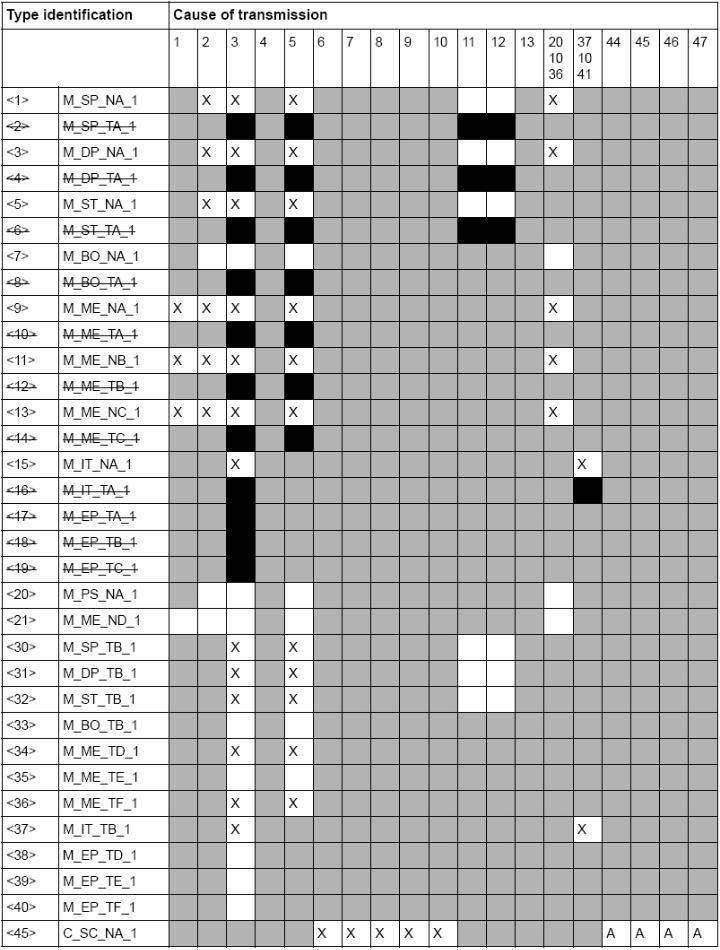
74 74
 Remote initialization")
75 Basic application functions Station limitations (station-specific parameter) Remote initialization 75
COM600 Station Automation Series IEC Slave (OPC) 3.2. User's Guide
 3.2. User's Guide") IEC 60870-5-101 1RS755382 Issued: 30.6.2004 Version: E/17.06.2008 IEC 60870-5-101 Contents: 1. About this manual... 7 1.1. Copyrights... 7 1.2. Trademarks... 7 1.3. General... 7 1.4. Document conventions...
IEC 60870-5-101 1RS755382 Issued: 30.6.2004 Version: E/17.06.2008 IEC 60870-5-101 Contents: 1. About this manual... 7 1.1. Copyrights... 7 1.2. Trademarks... 7 1.3. General... 7 1.4. Document conventions...
Grid Automation Controller COM IEC Slave (OPC) User's Manual
 User's Manual") Grid Automation Controller C600 4.0 1RS755384 Issued: 30.6.2004 Version: L/31.5.2012 Grid Automation Controller C600 4.0 Contents: 1. About this manual... 7 1.1. Copyrights... 7 1.2. Trademarks... 7 1.3.
Grid Automation Controller C600 4.0 1RS755384 Issued: 30.6.2004 Version: L/31.5.2012 Grid Automation Controller C600 4.0 Contents: 1. About this manual... 7 1.1. Copyrights... 7 1.2. Trademarks... 7 1.3.
Station Automation COM600 IEC Master (OPC) 3.3. User's Manual
 3.3. User's Manual") Station Automation C600 IEC 60870-5-101 1RS756703 Issued: 13.2.2009 Version: A/13.2.2009 Station Automation C600 IEC 60870-5-101 Contents: 1. About this manual... 7 1.1. Copyrights... 7 1.2. Trademarks...
Station Automation C600 IEC 60870-5-101 1RS756703 Issued: 13.2.2009 Version: A/13.2.2009 Station Automation C600 IEC 60870-5-101 Contents: 1. About this manual... 7 1.1. Copyrights... 7 1.2. Trademarks...
Station Automation COM IEC Master (OPC) User's Manual
 User's Manual") Station Automation C600 3.5 IEC 60870-5-101 aster (PC) User's anual 1RS756703 Issued: 13.2.2009 Version: C/30.06.2011 Station Automation C600 3.5 Contents: 1. About this manual... 7 1.1. Copyrights...
Station Automation C600 3.5 IEC 60870-5-101 aster (PC) User's anual 1RS756703 Issued: 13.2.2009 Version: C/30.06.2011 Station Automation C600 3.5 Contents: 1. About this manual... 7 1.1. Copyrights...
Station Automation COM IEC Master (OPC) User's Manual
 User's Manual") Station Automation C600 3.5 IEC 60870-5-104 aster (PC) User's anual 1RS756704 Issued: 13.2.2009 Version: C/30.06.2011 Station Automation C600 3.5 Contents: 1. About this manual... 7 1.1. Copyrights...
Station Automation C600 3.5 IEC 60870-5-104 aster (PC) User's anual 1RS756704 Issued: 13.2.2009 Version: C/30.06.2011 Station Automation C600 3.5 Contents: 1. About this manual... 7 1.1. Copyrights...
COM600 series, Version 5.0 Modbus Serial Slave (OPC) User's Manual
 User's Manual") CO600 series, Version 5.0 odbus Serial Slave (OPC) User's anual 1RS756913 Issued: 9.10.2009 Version: E/24.5.2017 CO600 series, Version 5.0 odbus Serial Slave (OPC) User's anual Contents: 1. About this
CO600 series, Version 5.0 odbus Serial Slave (OPC) User's anual 1RS756913 Issued: 9.10.2009 Version: E/24.5.2017 CO600 series, Version 5.0 odbus Serial Slave (OPC) User's anual Contents: 1. About this
Station Automation COM600 IEC Master (OPC) 3.3. User's Manual
 3.3. User's Manual") Station Automation C600 IEC 60870-5-103 1RS752278 Issued: 30.6.2004 Version: E/13.2.2009 Station Automation C600 IEC 60870-5-103 Contents: 1. About this manual... 7 1.1. Copyrights... 7 1.2. Trademarks...
Station Automation C600 IEC 60870-5-103 1RS752278 Issued: 30.6.2004 Version: E/13.2.2009 Station Automation C600 IEC 60870-5-103 Contents: 1. About this manual... 7 1.1. Copyrights... 7 1.2. Trademarks...
COM600 Station Automation Series External OPC Client Access 3.1. User's Guide
 COM600 Station Automation Series External OPC Client Access 3.1 1MRS755564 Issued: 10.03.2005 Version: C/21.12.2007 COM600 Station Automation Series External OPC Client Access 3.1 Contents: 1. About this
COM600 Station Automation Series MNS is Connectivity (OPC) 3.2. User's Guide
 3.2. User's Guide") MNS is Connectivity 3.2 User's Guide 1MRS756569 Issued: 17.06.2008 Version: A/17.06.2008 User's Guide MNS is Connectivity 3.2 Contents: 1. About this manual... 5 1.1. Copyrights... 5 1.2. Trademarks...
MNS is Connectivity 3.2 User's Guide 1MRS756569 Issued: 17.06.2008 Version: A/17.06.2008 User's Guide MNS is Connectivity 3.2 Contents: 1. About this manual... 5 1.1. Copyrights... 5 1.2. Trademarks...
Station Automation COM Logic Processor User's Manual
 Station Automation COM600 3.4 1MRS756738 Issued: 13.2.2009 Version: B/06.11.2009 Station Automation COM600 3.4 Contents: 1. About this manual... 5 1.1. Copyrights... 5 1.2. Trademarks... 5 1.3. General...
Station Automation COM600 DNP 3.0 LAN/WAN Master (OPC) 3.3. User's Manual
 3.3. User's Manual") Station Automation C600 DNP 3.0 (PC) 3.3 1RS756566 Issued: 17.06.2008 Version: B/13.2.2009 Station Automation C600 DNP 3.0 (PC) 3.3 Contents: 1. About this manual... 7 1.1. Copyrights... 7 1.2. Trademarks...
Station Automation C600 DNP 3.0 (PC) 3.3 1RS756566 Issued: 17.06.2008 Version: B/13.2.2009 Station Automation C600 DNP 3.0 (PC) 3.3 Contents: 1. About this manual... 7 1.1. Copyrights... 7 1.2. Trademarks...
Connectivity Packages. User's Guide - ANSI Version
 Connectivity Packages 1MRS756194 Issued: 30.11.2006 Version: A/30.11.2006 Connectivity Packages Contents Copyrights... 5 1. Introduction...... 7 1.1. Intended audience...... 7 1.2. Related documents.........
Station Automation COM600 Modbus TCP Master (OPC) 3.3. User's Manual
 3.3. User's Manual") Station Automation C600 odbus TCP aster (PC) 3.3 1RS756445 Issued: 21.12.2007 Version: C/13.2.2009 Station Automation C600 odbus TCP aster (PC) 3.3 Contents: 1. About this manual... 7 1.1. Copyrights...
Station Automation C600 odbus TCP aster (PC) 3.3 1RS756445 Issued: 21.12.2007 Version: C/13.2.2009 Station Automation C600 odbus TCP aster (PC) 3.3 Contents: 1. About this manual... 7 1.1. Copyrights...
System 800xA IEC Connect Configuration
 System 800xA IEC 61850 Connect Configuration System Version 6.0 Power and productivity for a better world System 800xA IEC 61850 Connect Configuration System Version 6.0 NOTICE This document contains
System 800xA IEC Connect Configuration
 System 800xA IEC 61850 Connect Configuration System Version 5.1 Power and productivity for a better world System 800xA IEC 61850 Connect Configuration System Version 5.1 NOTICE This document contains
MicroSCADA Pro SYS
 MicroSCADA Pro SYS 600 9.2 1MRS756170 Issued: 02.03.2007 Version: B/28.03.2008 MicroSCADA Pro SYS 600 9.2 Contents Copyrights...15 1. Introduction...17 1.1. This Manual...17 1.2. Use of symbols...17 1.3.
MicroSCADA Pro COM 500 *4.1. User s Guide
 MicroSCADA Pro COM 500 *4.1 1MRS751858-MEN Issued: 15.03.2002 Version: C/30.06.2004 MicroSCADA Pro COM 500 *4.1 1. About this manual...7 1.1. Copyrights...7 1.2. Trademarks...7 1.3. General...7 1.4. Use
MicroSCADA Pro SYS IEC Master Protocol
 SYS6 9.4 Trace back information: Workspace Main version a54 1MRS75819 Issued: 3.6.216 Version: C/3.6.216 Contents SYS6 9.4 1 Copyrights... 2 Introduction... 2.1 This manual... 2.2 Use of symbols... 2.3
SPA/ Ethernet Adapter
 1MRS755380 Issued: 23.11.2004 Version: F/20.05.2009 Contents Copyrights... 7 1. Introduction...9 1.1. This manual... 9 1.2. Use of symbols... 9 1.3. Intended audience... 9 1.4. Product documentation...
Ethernet Adapter. SPA to IEC Gateway. Installation and Commissioning Manual
 SPA-ZC 400 1MRS755347 Issued: 06.10.2004 Version: G/20.05.2009 SPA-ZC 400 Contents Copyrights... 7 1. Introduction...9 1.1. This manual... 9 1.2. Use of symbols... 9 1.3. Intended audience... 9 1.4. Product
Station Automation COM HMI Configuration Manual
 Station Automation COM600 3.4 1MRS756740 Issued: 13.2.2009 Version: B/06.11.2009 Station Automation COM600 3.4 Contents: 1. About this manual... 5 1.1. Copyrights... 5 1.2. Trademarks... 5 1.3. General...
MicroSCADA Pro SYS Connecting LONWORKS Devices
 MicroSCADA Pro SYS 600 9.3 1MRS756638 Issued: 31.3.2010 Version: A/31.3.2010 MicroSCADA Pro SYS 600 9.3 Contents Copyrights...7 1. Introduction...9 1.1. This manual...9 1.2. Document conventions...9 1.3.
MicroSCADA Pro. IEC System Design. Configuration Manual
 SYS 600 9.2 1MRS756119 Issued: 23.03.2007 Version: A/23.03.2007 SYS 600 9.2 Contents Copyrights... 5 1. Introduction...7 1.1. This manual... 7 1.2. Use of symbols... 7 1.3. Intended audience... 7 1.4.
IEC Master Driver Help Kepware Technologies
 IEC 60870-5-104 Master Driver Help 2014 Kepware Technologies IEC 60870-5-104 Master Help 2 Table of Contents Table of Contents 2 IEC 60870-5-104 Master Driver Help 3 Overview 3 Channel Setup 4 60870 Settings
MicroSCADA Pro SYS Operation Manual
 MicroSCADA Pro SYS 600 9.2 1MRS756118 Issued: 28.02.2007 Version: B/28.03.2008 MicroSCADA Pro SYS 600 9.2 Contents Copyrights...7 1. Introduction...9 1.1. This manual...9 1.2. Use of symbols...9 1.3.
Protection System Simulator SIM600. Installation Manual
 Protection System Simulator SIM600 1MRS756102 Issued: 08.12.2008 Version: B Protection System Simulator SIM600 Contents: 1. About this manual... 5 1.1. Copyrights... 5 1.2. Trademarks... 5 1.3. Guarantee...
COM600 series 5.0 Operator's Manual
 COM600 series 5.0 1MRS756705 Issued: 13.2.2009 Version: F/24.5.2017 COM600 series 5.0 Contents: 1. About this manual... 5 1.1. Copyright... 5 1.2. Disclaimer... 5 1.3. Conformity... 6 1.4. Trademarks...
MicroSCADA Pro SYS Operation Manual
 SYS 600 9.3 Trace back information: Workspace Main version a9 Checked in 2012-11-09 1MRS756635 Issued: 31.3.2010 Version: C/30.09.2012 SYS 600 9.3 Contents 1 Copyrights... 2 Introduction... 2.1 This manual...
IEC Master Driver Help Kepware Technologies
 IEC 60870-5-101 Master Driver Help 2014 Kepware Technologies IEC 60870-5-101 Master Driver 2 Table of Contents Table of Contents 2 IEC 60870-5-101 Master Driver Help 3 Overview 3 Channel Setup 4 Device
MicroSCADA Pro SYS IEC Slave Protocol
 SYS600 9.4 Trace back information: Workspace Main version a54 1MRS758106 Issued: 3.6.2016 Version: C/3.6.2016 Contents SYS600 9.4 1 Copyrights... 2 Introduction... 2.1 This manual... 2.2 Use of symbols...
Industrial IT. Fieldbus Basic PROFIBUS DTM / PROFIBUS DTM Builder Version 4.1. Configuration
 Industrial IT Fieldbus Basic PROFIBUS DTM / PROFIBUS DTM Builder Version 4.1 Configuration Industrial IT Fieldbus Basic PROFIBUS DTM / PROFIBUS DTM Builder Version 4.1 Configuration NOTICE The information
Protection Terminal REF 54_ Protection Relay REX 521
 Protection Terminal Protection Relay 1MRS755260 Issued: 02.04.2004 Version: C/22.06.2004 Protection Terminal Protection Relay Contents 1. About this manual...4 1.1. Copyrights...4 1.2. Trademarks...4
Protocol Gateway IEC Master/Slave IEC Client/Server
 Atop Technologies, Inc. Protocol Gateway IEC60870-5-101 Master/Slave IEC60870-5-104 Client/Server Protocol and enode Designer configuration enode Configuration Manual V1.2 September 29 th, 2017 CLIENT/SERVER
MicroSCADA Pro SYS IEC System Design
 SYS600 9.4 Trace back information: Workspace Main version a54 1MRS758117 Issued: 3.6.2016 Version: C/3.6.2016 SYS600 9.4 Contents 1 Copyrights... 2 Introduction... 2.1 This manual... 2.2 Use of symbols...
Engineering Manual Security Lock
 DigiVis 500 Engineering Manual Security Lock Version 1.0 SP1 DigiVis 500 Engineering Manual Security Lock Version 1.0 SP1 NOTICE The information in this document is subject to change without notice and
MicroSCADA Pro SYS
 MicroSCADA Pro SYS 600 9.2 1MRS756117 Issued: 02.03.2007 Version: B/28.03.2008 MicroSCADA Pro SYS 600 9.2 Contents Copyrights...7 1. Introduction...9 1.1. This manual...9 1.2. Use of symbols...10 1.3.
MicroSCADA Pro SYS IEC Master Protocol
 SYS600 9.4 Trace back information: Workspace Main version a26 Checked in 2014-05-16 1MRS758093 Issued: 16.5.2014 Version: A/16.5.2014 Contents SYS600 9.4 1 Copyrights... 2 Introduction... 2.1 This manual...
Ethernet Adapter. Modbus/TCP Brigde. Installation and Commissioning Manual
 SPA-ZC 400 1MRS756014 Issued: 30.06.2006 Version: B/20.05.2009 SPA-ZC 400 Contents Copyrights... 5 1. Introduction...7 1.1. This manual... 7 1.2. Use of symbols... 7 1.3. Intended audience... 7 1.4. Product
Industrial IT. 800xA - System PLC Connect System Version 4.0. Operation
 Industrial IT 800xA - System PLC Connect System Version 4.0 Operation Industrial IT 800xA - System PLC Connect System Version 4.0 Operation NOTICE The information in this document is subject to change
MicroSCADA Pro DMS Operation Manual
 DMS 600 4.2 1MRS755274 Issued: 30.6.2004 Version: E/28.3.2008 DMS 600 4.2 Contents: 1. About this manual... 11 1.1. Copyrights... 11 1.2. Trademarks... 11 1.3. General... 11 1.4. Use of symbols... 12
TOP Server V5 to MicroLogix Using DNP3 Ethernet Driver
 TOP Server V5 to MicroLogix 1400 Using DNP3 Ethernet Driver Page 2 of 36 Table of Contents INTRODUCTION 3 CONFIGURING THE MICROLOGIX 1400 AS A DNP3 SLAVE 4 CONFIGURING TOP SERVER AS A DNP3 MASTER 9 TESTING
IEC Master Driver PTC Inc. All Rights Reserved.
 2017 PTC Inc. All Rights Reserved. 2 Table of Contents 1 Table of Contents 2 4 Overview 4 Setup 5 Channel Properties General 5 Channel Properties Ethernet Communications 6 Channel Properties Write Optimizations
MicroSCADA Pro SYS External OPC Data Access Client
 SYS600 9.4 Trace back information: Workspace Main version a54 1MRS758101 Issued: 3.6.2016 Version: C/3.6.2016 SYS600 9.4 Contents 1 Copyrights... 2 About this manual... 2.1 General... 2.2 Use of symbols...
IEC Master Driver PTC Inc. All Rights Reserved.
 2018 PTC Inc. All Rights Reserved. 2 Table of Contents 1 Table of Contents 2 4 Overview 4 Setup 5 Channel Properties General 5 Channel Properties Serial Communications 6 Channel Properties Write Optimizations
CAP 505. User s Guide
 CAP 505 1MRS752292-MUM CAP 505 Issued: 04.10.2002 Version: L/05.01.2005 1. About this manual...7 1.1. Copyrights...7 1.2. Trademarks...7 1.3. General...7 1.4. Use of symbols...8 1.5. Abbreviations...8
MicroSCADA Pro DMS 600 *4.0. Operation Manual
 MicroSCADA Pro DMS 600 *4.0 1MRS755274 MicroSCADA Pro DMS 600 *4.0 Issued: 30.6.2004 Version: A/30.6.2004 Contents: 1. About this manual... 11 1.1. Copyrights...11 1.2. Trademarks...11 1.3. General...11
MicroSCADA Pro DMS 600 *4.1. Operation Manual
 MicroSCADA Pro DMS 600 *4.1 1MRS755274 MicroSCADA Pro DMS 600 *4.1 Issued: 30.6.2004 Version: C/28.2.2005 Contents: 1. About this manual... 11 1.1. Copyrights... 11 1.2. Trademarks... 11 1.3. General...
MicroSCADA Pro SYS IEC Slave Protocol
 SYS 600 9.3 Trace back information: Workspace Main version a9 Checked in 2012-11-09 1MRS756653 Issued: 31.3.2010 Version: B/30.9.2012 Contents SYS 600 9.3 1 Copyrights... 2 Introduction... 2.1 This manual...
SCL Tool. Configuration manual
 REF 542plus 1MRS756342 Issued: 30.04.2007 Version: A/31.05.2007 REF 542plus Contents Copyrights... 5 1. Introduction...7 1.1. This manual... 7 1.2. Use of symbols... 7 1.3. Product documentation... 8
IED Configurator. User Manual
 SystemCORP Embedded Technology Pty Ltd This PDF Document contains internal hyperlinks for ease of navigation. For example, click on any item listed in the Table of Contents to go to that page. General
Experion LX Safety Manager Integration Guide
 Experion LX Safety Manager Integration Guide EXDOC-X119-en-110A February 2014 Release 110 Document Release Issue Date EXDOC-X119-en-1 0A 0 February 2014 Disclaimer This document contains Honeywell proprietary
Inform IT. Enterprise Historian TM and Profile Historian. Release Notes. Version 3.2/1 Patch 4 for History Services
 Inform IT Enterprise Historian TM and Profile Historian Version 3.2/1 Patch 4 for History Services Release Notes NOTICE The information in this document is subject to change without notice and should not
IEC61850 communication solution WinCC Channel
 IEC61850 communication solution WinCC Channel Documentation Date: 15.04.2015 Version: 2.03 IEC 61850 communication solution Page 1 of 33 Change history Datum Version Author Changes 19.11.2010 00.1 Mr.
Multifunction Protection and Switchgear Control Unit. Operator's manual
 REF 542plus 1MRS755869 Issued: 01.11.2002 Version: C/31.05.2007 REF 542plus Contents Copyrights... 7 1. Introduction...9 1.1. This manual... 9 1.2. Use of symbols... 9 1.3. Intended audience... 9 1.4.
MicroSCADA Pro SYS 600 *9.1
 MicroSCADA Pro SYS 600 *9.1 1MRS751964-MEN Issued: 15.03.2002 Version: C/25.02.2005 MicroSCADA Pro SYS 600 *9.1 1. About this manual...5 1.1. Copyrights...5 1.2. Trademarks...5 1.3. General...5 1.4. Related
System 800xA 800xA for Freelance Product Guide
 System 800xA 800xA for Freelance Product Guide System Version 6.0 Power and productivity for a better world TM System 800xA 800xA for Freelance Product Guide System Version 6.0 NOTICE This document contains
ABB ABB Oy, Distribution Automation
 ABB ABB Oy, Distribution Automation Guideline Issued: May 2012 Revision: A / 15 May 2012 COM600 Engineering process overview Engineering approach with.cid files in the SAB600 tool Contents: 1 Scope...
Protection and Control IED Manager PCM600 Getting Started Guide
 Protection and Control IED Manager PCM600 Document ID: 1MRS757866 Issued: 2018-04-18 Revision: C Product version: 2.9 Copyright 2018 ABB. All rights reserved Copyright This document and parts thereof
Industrial IT. 800xA - Engineering System Version 4.1. Graphics
 Industrial IT 800xA - Engineering System Version 4.1 Graphics Industrial IT 800xA - Engineering System Version 4.1 Graphics NOTICE The information in this document is subject to change without notice
INTERNATIONAL STANDARD
 INTERNATIONAL STANDARD IEC 61850-7-3 First edition 2003-05 Communication networks and systems in substations Part 7-3: Basic communication structure for substation and feeder equipment Common data classes
S900 I/O DTM 6.x. System Version 6.0. Power and productivity for a better world TM
 S900 I/O DTM 6.x System Version 6.0 Power and productivity for a better world TM S900 I/O DTM 6.x NOTICE This document contains information about one or more ABB products and may include a description
Series PM130 PLUS Powermeters PM130P/PM130E/PM130EH
 Series PM130 PLUS Powermeters PM130P/PM130E/PM130EH IEC60870-5-101/104 Communications Protocol Reference Guide BG0503 Rev. A3 Every effort has been made to ensure that the material herein is complete and
Protect IT MNS Motor Management INSUM. Dual Redundancy Guide Version 2.3 ABB
 Protect IT MNS Motor Management INSUM Version 2.3 ABB Network Management Guide INSUM Version 2.3 1 NOTICE The information in this document is subject to change without notice and should not be construed
MicroSCADA Pro LIB 510 *4.1. Operation Manual
 MicroSCADA Pro LIB 510 *4.1 1MRS755361 Issued: 30.06.2004 Version: B/20.12.2004 MicroSCADA Pro LIB 510 *4.1 1. About this manual...7 1.1. Copyrights...7 1.2. Trademarks...7 1.3. General...7 1.4. Use of
MicroSCADA Pro SYS Historian Monitor Configuration
 SYS600 9.4 Trace back information: Workspace Main version a26 Checked in 2014-05-16 1MRS758121 Issued: 16.5.2014 Version: A/16.5.2014 SYS600 9.4 Contents 1 Copyrights... 2 Introduction... 2.1 This manual...
MODBUS Protocol for MiCOM P30 Series
 MODBUS Protocol for MiCOM P30 Series Substation Protocols Technical Documentation This document does not replace the Technical Manual Version: MiCOM P30, MODBUS Index: B Release: 08 / 2011 MODBUS Protocol
Relion Protection and Control. 615 series IEC Communication Protocol Manual
 Relion Protection and Control 615 series IEC 60870-5-103 Communication Protocol Manual Document ID: 1MRS756710 Issued: 2016-05-20 Revision: G Product version: 5.0 FP1 Copyright 2016 ABB. All rights reserved
User Manual AXON TEST V3.8 IKELOS. Simulator
 AXON TEST V3.8 IKELOS Simulator 2 2014 Axon Group Ltd., Manual The information contained in this document is subject to change without notice. Axon Group Ltda Making great things Technology Development
Relion Protection and Control. 611 series IEC Engineering Guide
 Relion Protection and Control 611 series IEC 61850 Document ID: 1MRS757465 Issued: 2016-02-22 Revision: B Product version: 2.0 Copyright 2016 ABB. All rights reserved Copyright This document and parts
Communication 7. What's in this Chapter? This chapter contains the following sections:
 Communication 7 What's in this Chapter? This chapter contains the following sections: Section Topic Page 7.1 Modbus Protocol 170 7.2 IEC 60870-5-103 protocol 190 SEPED307003 02/2008 169 7.1 Modbus Protocol
MicroSCADA Pro SYS Historian Monitor Configuration
 SYS 600 9.3 Trace back information: Workspace Main version a10 Checked in 2012-11-12 1MRS757708 Issued: 30.9.2012 Version: A/30.9.2012 SYS 600 9.3 Contents 1 Copyrights... 2 Introduction... 2.1 This manual...
Functional Description DOC01 - Digital Operator Control Version 5.2-0
 Functional Description DOC01 - Digital Operator Control Version 5.2-0 3BTG811792-3021 / A Page 1 NOTICE The information in this document is subject to change without notice and should not be construed
MicroSCADA Pro SYS
 MicroSCADA Pro SYS 600 9.2 1MRS756158 Issued: 15.11.2006 Version: A/15.11.2006 MicroSCADA Pro SYS 600 9.2 Contents Copyrights...5 1. Introduction...7 1.1. This manual...7 1.2. Use of symbols...8 1.3.
DNP3 Master Serial Driver PTC Inc. All Rights Reserved.
 2018 PTC Inc. All Rights Reserved. 2 Table of Contents 1 Table of Contents 2 9 Overview 9 Setup 9 Channel Properties General 10 Channel Properties Serial Communications 11 Channel Properties Write Optimizations
Functional Description DIS01 - Digital Input Signal Version 5.2-0
 Functional Description DIS01 - Digital Input Signal Version 5.2-0 3BTG811792-3020 / A Page 1 NOTICE The information in this document is subject to change without notice and should not be construed as a
MVI46-103M. User Manual. SLC Platform. IEC Master Communication Module
 MVI46-103M SLC Platform IEC 60870-5-103 Master Communication Module User Manual Please Read This Notice Successful application of this module requires a reasonable working knowledge of the Rockwell Automation
MicroSCADA Pro SYS 600 *9.1
 MicroSCADA Pro SYS 600 *9.1 1MRS751859-MEN Issued: 15.03.2002 Version: C/25.2.2005 MicroSCADA Pro SYS 600 *9.1 1. About this manual...5 1.1. Copyrights...5 1.2. Trademarks...5 1.3. General...5 1.4. Related
Protection and Control IED Manager PCM600 Product Guide
 Protection and Control IED Manager Product Guide Protection and Control IED Manager Product version: 2.9 Contents 1. Description... 3 2. Project explorer... 3 3. Parameter setting... 3 4. Graphical application
MicroSCADA Pro SYS Historian Operation
 SYS 600 9.3 Trace back information: Workspace Main version a10 Checked in 2012-11-12 1MRS757707 Issued: 30.9.2012 Version: A/30.9.2012 SYS 600 9.3 Contents 1 Copyrights... 2 Introduction... 2.1 This manual...
System 800xA Multisystem Integration
 System 800xA Multisystem Integration System Version 5.1 Power and productivity for a better world T System 800xA Multisystem Integration System Version 5.1 NOTICE This document contains information about
IEC MMS Client Driver Help Kepware Technologies
 Help 2014 Kepware Technologies 2 Table of Contents Table of Contents 2 Help 3 Overview 3 Device Setup 4 Automatic Configuration 4 Connection 5 Communication 8 Control 9 Tag Database Settings 10 Data Types
Device Management Basic HART DTM 6.0 Installation
 Device Management Basic HART DTM 6.0 Installation System Version 6.0 Power and productivity for a better world TM Device Management Basic HART DTM 6.0 Installation System Version 6.0 NOTICE This document
EuroGateway. IEC Substation Automation System Communication Gateway
 EuroGateway IEC 61850 Substation Automation System Communication Gateway Basic Configuration Introduction Communication gateway Substation SCADA Substation HMI IEC 61850 client Temporary storage (disturbance
Overcurrent and Earth-Fault Relay REJ 525. Technical Reference Manual
 Overcurrent and Earth-Fault Relay MRS75094-MUM Issued: 4.09.998 Version: D/4..2005 Overcurrent and Earth-Fault Relay Contents. About this manual...5.. Copyrights...5.2. Trademarks...5.3. Guarantee...5.4.
INSTRUCTION MANUAL. Web server description. AQ 300 Series
 INSTRUCTION MANUAL Web server description AQ 300 Series Instruction manual Web server description 2 (22) Revision 1.0 Date August 2013 Changes - N/A Instruction manual Web server description 3 (22) TABLE
MicroSCADA Pro SYS 600 *9.1
 MicroSCADA Pro SYS 600 *9.1 1MRS751965-MEN Issued: 15.03.2002 Version: C/25.02.2005 MicroSCADA Pro SYS 600 *9.1 Contents 1. About this manual...5 1.1. Copyrights...5 1.2. Trademarks...5 1.3. General...5
IEC MMS Client Driver Help Kepware Technologies
 IEC 61850 MMS Client Driver Help 2014 Kepware Technologies 2 Table of Contents Table of Contents 2 Help 3 Overview 3 Device Setup 4 Automatic Configuration 4 Connection 5 Communication 8 Control 8 Tag
IntesisBox MAPS. Configuration & monitoring software of IntesisBox KNX series. User's manual Issue Date: 06/17 r1.0 eng
 IntesisBox MAPS Configuration & monitoring software of IntesisBox KNX series User's manual Issue Date: 06/17 r1.0 eng Intesis Software S.L.U. 2017 All Rights Reserved. Information in this document is subject
Plant / field level Process
 FM Telecontrol IEC 60870-5 Client and Server (Master and Slave) For communication in accordance with IEC 60870-5-101, -103 and -104 Control station Application areas The remote control protocol, according
DAQ Electronics, Inc 262B Old New Brunswick Road, Piscataway, NJ
 DAQ Electronics, Inc 262B Old New Brunswick Road, Piscataway, NJ 08854-3756 DNP3 Server Configuration CallistoView version 5.0A This is a description of the unique DNP configuration dialogs and files in
Enron Modbus Driver PTC Inc. All Rights Reserved.
 2017 PTC Inc. All Rights Reserved. 2 Table of Contents 1 Table of Contents 2 5 Overview 5 Channel Setup 6 Channel Properties - General 6 Channel Properties - Serial Communications 7 Channel Properties
Grid Automation Controller COM600 How it fits into the Smart Grid?
 ABB Oy Distribution Automation Grid Automation Controller How it fits into the Smart Grid? May 27, 2014 Slide 1 1MRS756763 E Content Technical Presentation May 27, 2014 Slide 2 Description Grid Automation
Chapter 6: DNP Introduction. 6.2 Features of the DNP The OSI/ISO model. 6.3 Basic topology
 6.1 Introduction DNP3 (Distributed Network Protocol Version 3) is an open, intelligent, robust and efficient modern SCADA protocol designed to optimise the transmission of data acquisition information
Enterprise Historian TM History Services. Version 2.4/1 Patch 8. Release Notes
 Enterprise Historian TM History Services Version 2.4/1 Patch 8 Release Notes NOTICE The information in this document is subject to change without notice and should not be construed as a commitment by ABB
TESLA Firmware v2.1. Release Description
 TESLA 4000 Firmware v2.1 Release Description FEATURE ENHANCEMENTS Cyber Security: o Added support for allowing TESLA Control Panel, RecordBase Central Station, and FTP to connect to the IED using configurable
Protection and Control IED Manager PCM600 Product Guide
 Product Guide Contents 1. Description...3 2. Project explorer...4 3. Parameter setting...4 4. Graphical application configuration...4 5. Signal matrix...5 6. Graphical display editor...5 7. Hardware configuration...6
CO General Specifications GS48D62Z00-00E-N GENERAL. ProSafe-COM extended communication system
 General Specifications GS48D62Z00-00E-N CO-962-00 ProSafe-COM extended communication system GENERAL Figure 1 ProSafe-COM extended communication system is a multiple protocol communication interface connecting
Industrial IT. 800xA - System System Version 4.1. Post Installation
 Industrial IT 800xA - System System Version 4.1 Post Installation Industrial IT 800xA - System System Version 4.1 Post Installation NOTICE The information in this document is subject to change without
DNP Master Serial Driver Help Kepware Technologies
 DNP Master Serial Driver Help 2013 Kepware Technologies 2 Table of Contents Table of Contents 2 8 Overview 8 Channel Setup 9 Timing 9 Device Setup 10 Communications 10 Polling 13 Unsolicited Messaging
System 800xA 800xA for Freelance Configuration
 System 800xA 800xA for Freelance Configuration System Version 6.0 Power and productivity for a better world System 800xA 800xA for Freelance Configuration System Version 6.0 System Version 6.0 NOTICE