UNIT IV. Bharati Vidyapeeth s Institute of Computer Applications and Management, New Delhi-63, by Anukiran Jian U4. #
|
|
|
- Damon Lambert
- 6 years ago
- Views:
Transcription
1 OBJECT ANALYSIS AND DESIGN UNIT IV Bharati Vidyapeeth s Institute of Computer Applications and Management, New Delhi-63, by Anukiran Jian
2 Learning Objectives Modeling with UML Basic Building Blocks of UML A Conceptual Model of UML Basic Structural Modeling UML Diagrams Case Studies
3 OOAD Overview of the UML Bharati Vidyapeeth s Institute of Computer Applications and Management, New Delhi-63, by Anukiran Jian
4 Learning Objectives What is Visual Modeling? History of the UML Unified Modeling Language (UML) Overview Architecture & Views Basic Building Blocks of UML Structural Things Behavioral Things Grouping Things Annotational Things Relationship UML Diagrams
5 Learning Objectives Cont.. Extensibility of UML Using UML Concepts in a Nutshell Rules of UML Process for Using UML
6 What is Visual Modeling? Item Order Modeling captures essential parts of the system. Dr. James Rumbaugh Ship via Business Process Visual Modeling is modeling using standard graphical notations Computer System
7 Visual Modeling Captures Business Process Use Case Analysis is a technique to capture business process from user s perspective


8 Visual Modeling is a Communication Tool Use visual modeling to capture business objects and logic Use visual modeling to analyze and design your application
9 Visual Modeling : Manages Complexity
 Business")

10 Visual Modeling Defines Software Architecture User Interface (Visual Basic, Java) Business Logic (C++, Java) Database Server (C++ & SQL) Model your system independent of implementation language

11 Visual Modeling :Promotes Reuse Multiple Systems Reusable Components
12 History of the UML Nov 97 UML approved by the OMG Schlaer /Mellor Prehistory Booch Fusion 1 st unification attempt OMT, Booch, CRC UML work begins OMG (RFP) UML Proposal accepted by OMG UML 1.X UML 2.0 RamBaugh (OMT) Jacobson (Objectory ) Coad/ Yourdeon Booch(OOD) & Rambaugh (OMT) join Rational Jacobson (Objectory) joins Rational UML becomes an industry standard Ongoing UML development
13 Unified Modeling Language (UML) An effort by Rational to standardize OOA&D notation a graphical language for visualizing, specifying, constructing, and documenting the artifacts of a software intensive system [Booch] UML attempts to combine the best of the best from Data Modeling concepts (Entity Relationship Diagrams) Business Modeling (work flow) Object Modeling Component Modeling Offers vocabulary and rules for communication Focus on conceptual and physical representations of a system Not a process but a language
14 UML is for Visual Modeling A picture is worth a thousand words! Uses standard graphical notations Semi-formal Captures Business Process from enterprise information systems to distributed Web-based applications and even to hard real time embedded systems
15 Specifying Building models that are Precise Unambiguous Complete Symbols are based on well-defined syntax semantics. UML is also for Addresses the specification of all important analysis, design, and implementation decisions.
16 UML is also for Constructing Models are related to OO programming languages. Round-trip engineering requires tool and human intervention to avoid information loss Forward engineering direct mapping of a UML model into code. Reverse engineering g reconstruction of a UML model from an implementation.
17 UML is also for Documenting Architecture Requirements Tests Activities Project planning Release management
18 Three (3) Basic Building Blocks of UML Things important modeling concepts Relationships tying individual things together Diagrams grouping interrelated collections of things and relationships
19 3 Basic Building Blocks of UML - Things Structural nouns of UML models. Behavioral dynamic (verbal) parts of UML models. Grouping organizational parts of UML models. Annotational explanatory parts of UML models.
 close( ) move( ) IWindow Interface Collaboration Chain of Responsibility Place Order Use Case Conceptual or Active Class")
20 Structural Things in UML- 7 Kinds Nouns of UML models physical elements. Class Window origin size open( ) close( ) move( ) IWindow Interface Collaboration Chain of Responsibility Place Order Use Case Conceptual or Active Class Event Mgr thread time suspend( ) flush( () stop( ) listbox Component Node WebServer
21 Structural Things in UML 1. Class A description of a set of objects that share the same attributes, operations, relationships, and semantics. name attributes operations Window origin size open() close() IWindow 2. Interface A collection of operations that specify a service (for aresourceor an action) of a class or component. name It describes the externally visible behavior of that element. operations open() close() <<interface>> IWindow
22 Structural Things in UML 1. Class A description of a set of objects that share the same attributes, operations, relationships, and semantics. name attributes operations Window origin size open() close() IWindow 2. Interface A collection of operations that specify a service (for aresourceor an action) of a class or component. name It describes the externally visible behavior of that element. operations open() close() <<interface>> IWindow
23 3. Collaboration Structural Things in UML.. Define an interaction among two or more classes. Define a society of roles and other elements. Provide cooperative behavior. Capture structural and behavioral dimensions. UML uses pattern as a synonym Chain of Responsibility
24 Structural Things in UML.. 4. Use Case A sequence of actions that produce an observable result for a specific actor. A set of scenarios tied together by a common user goal. Provides a structure for behavioral things. Realized through a collaboration Place Order
25 Structural Things in UML.. 5. Active Class name attributes operations Event Manager Thread time suspend() flush() Heavy border Special class whose objects own one or more processes or threads. Can initiate control activity.
26 Structural Things in UML.. 6. Component Replaceable part of a system. Components can be packaged logically. Od Orderform.java Conforms to a set of interfaces. Provides the realization of an interface. Represents a physical module of code
27 Structural Things in UML.. 7. Node Element that exists at run time. Representsacomputational resource. Generally has memory and processing power. WebServer
28 Verbs of UML models. Behavioral Things in UML Dynamic parts of UML models: behavior over time and space Usually connected to structural things in UML.
29 Behavioral Things in UML.. Two primary kinds of behavioral things: Interaction behavior of a set of objects comprising of a set of message exchanges within a particular context to accomplish a specific purpose. display State Machine behavior that specifies the sequences of states an object or an interaction goes through during its lifetime in response to events, together with its responses to those events. Idle Waiting
30 Grouping Things in UML Packages one primary kind of grouping. Meeting Scheduler General purpose mechanism for organizing elements into groups. Purely conceptual; only exists at development time. Contains behavioral and structural things. Can be nested. Variations of packages are: Frameworks, models, & subsystems.
31 Annotational Things in UML Explanatory parts of UML models Comments regarding other UML elements (usually called adornments in UML) Note is the one primary annotational ti thing in UML best expressed in informal or formal text. flexible drop-out dates
32 3 basic building blocks of UML - Relationships Dependency Association Generalization
33 Generalization Inheritance: a solid line with a solid arrowhead that points from a sub-class to a superclass or from a sub-interface to its super-interface. Super Class Sub Class Implementation: a dotted line with a solid arrowhead that points from a class to the interface that it implement Class interface
34 Association a solid line with an open arrowhead that represents a "has a" relationship. The arrow points from the containing to the contained class. Associations can be one of the following two types or not specified. 1. Composition 2. Aggregation
35 Association Composition: Represented by an association line with a solid diamond at the tail end. A composition models the notion of one object "owning" another and thus being responsible for the creation and destruction of another object. Aggregation: Represented by an association line with a hollow diamond at the tail end. An aggregation models the notion that one object uses another object without "owning" it and thus is not responsible for its creation or destruction.
36 Composition // WebServer is composed of a HttpListener and a RequestPro cessor public class WebServer { private HttpListener listener; private RequestProcessor processor; public WebServer(HttpListener listener, RequestProcessor processor) { this.listener = listener; this.processor = processor; } }
37 Aggregation // WebServer is an aggregate of HttpListener and RequestProc essor // and controls their lifecycle public class WebServer { private HttpListener listener; private RequestProcessor processor; public WebServer() { this.listener = new HttpListener(80); this.processor = new RequestProcessor("/www/root"); (/ / } }
38 Dependency a dotted line with an open arrowhead that shows one entity depends on the behavior of another entity. Typical usages are to represent that one class instantiates another or that it uses the other as an input parameter
39 3 basic building blocks of UML - Diagrams Graphical representation of a set of elements. Represented by a connected graph: Vertices are things; Arcs are behaviors. 5 most common views built from 9 diagram types. 1.Class Diagram; Object Diagram 2. Use case Diagram 3. Sequence Diagram; Collaboration Diagram 4. Statechart t t Diagram 5. Activity Diagram 6. Component Diagram 7. Deployment Diagram
40 The UML Provides Standardized Diagrams Use Case Diagrams Use Case Diagrams Activity Diagrams Use Case Diagrams Use Case Diagrams Use Case Diagrams State Diagrams State Diagrams Class Diagrams State Diagrams State Diagrams Object Diagrams Scenario Diagrams Scenario Diagrams Sequence Diagrams Model State Diagrams State Diagrams Deployment Diagrams Scenario Diagrams Scenario Collaboration Diagrams Diagrams State Diagram Component Diagrams Component Diagrams Component Diagrams
41 Use-case Diagram It shows a set of use cases and actors and their relationships. It helps the analyst to discover the requirements of the target system from the user s s perspective. It is depicted as follows in Rational Rose :
42 Use-case Diagram book ticket employee status check
43 Activity Diagram It s a special kind of a state chart diagram that shows the flow from activity to activity within the system. Its depicted as follows in Rational Rose :
44 Activity Diagram enter data book ticket Check Availabilty
45 Class Diagram It shows a set of classes and their relationships. It addresses the static design view of a system. Its depicted as follows in Rational Rose :
46 Class Diagram Student Name Phone Number Address Is Eligible to Enroll (Provides to seminar taken) Lives at Address Street City Postal code Validate as Output Label
47 Interaction Diagrams An interaction diagram shows an interaction, consisting of a set of objects and their relationships, include the messages that may be exchanged between them Model the dynamic aspect of the system Contain two sort of diagrams: Sequence diagrams, show the messages objects send to each other in a timely manner Collaboration diagrams, show the organization of the objects participating in an interaction
48 Sequence Diagram It is an interaction diagram that emphasizes the time ordering of messages. It is drawn in Rational Rose as in next slide
49
50 Collaboration Diagram Its an interaction diagram that emphasizes the structural organization of the objects that send and receive messages. It is drawn in Rational Rose as in next slide
51
52 Sequence v/s Collaboration Semantically both are the same Express different sides of the model Sequence diagram expresses time ordering Collaboration diagram is used to define class behavior
53 Component Diagram The main purpose of component diagram is to show the structural t relationship between components of the system. Its depicted as follows in Rational Rose :
54 Component Diagram
55 Deployment Diagram The deployment diagram shows how a system will be physically deployed in the hardware environment. Its depicted as follows in Rational Rose :
56 Deployment Diagram Server Component Component
57 State Chart Diagram It shows a state machine, consisting of states, transitions, events and activities. It addresses the dynamic view of a system. Its depicted as follows in Rational Rose :
58 State Chart Diagram Term Started Classes End Enrollment Being Taught Final Exams Cancelled Student Dropped Closed Seminar Size>0 Seminar Size = 0
59 Object Diagram A pictorial representation of the relationships between the instantiated classes at any point of time. Its depicted as follows in Rational Rose:
60 Object Diagram John Smith: Student Sally Jones: Student Seminar Term: Fall Semester Seminar : Course Intro to Computer Science Mike Sean: Student Term: "Spring Semester
61 Extensibility of UML Stereotypes can be used to extend the UML notational elements (extends vocabulary.) Name shown in guillements <<stereotype>> t t Stereotypes may be used to classify and extend associations, inheritance relationships, p, classes, and components Examples: Class stereotypes: boundary, control, entity, utility, exception Inheritance stereotypes: includes and extends Component stereotypes: subsystem
62 Extensibility of UML Tagged values extends properties of UML building blocks. Placed in braces beneath the name of the element to which the property applies Constraints extend the semantics of UML building blocks. A string placed in braces {if Order.customer.credit.Rating customercredit is poor then Order.isPrepaid must be true}
63 Architecture & Views Architecture - set of significant decisions regarding: Organization of a software system. Selection of structural elements & interfaces from which a system is composed. Behavior or collaboration of elements. Composition of structural and behavioral elements. Architectural style guiding g the system.
64 UML have five different views Usecase View Design View Implementation View Process View Deployment View Architecture & Views..
65 Architecture & Views.. vocabulary functionality Design View (Logical View) behavior Use Case View Implementation View system assembly configuration mgmt. Process View Deployment tview performance scalability throughput system topology distributionib i delivery installation
66 Use Case View Technique to capture business process from user s perspective. Encompasses the behavior as seen by users, analysts and testers. Specifies forces that shape the architecture. Static aspects captured in use case diagrams. Dynamic aspects captured in interaction diagrams, statechart diagrams, and activity diagrams.
67 Design View (Logical View) Encompasses classes, interfaces, and collaborations that define the vocabulary of a system. Supports functional requirements of the system. Static aspects captured in class diagrams and object diagrams. Dynamic aspects captured in interaction, statechart, and activity diagrams.
68 Process View Encompasses the threads and processes defining concurrency and synchronization. Addresses performance, scalability, and throughput. Static and dynamic aspects captured as in design view; emphasis on active classes.
69 Implementation View Encompasses components and files used to assemble and release a physical system. Addresses configuration management. Static aspects captured in component diagrams. Dynamic aspects captured in interaction, statechart, & activity diagrams.
70 Deployment View Encompasses the nodes that form the system hardware topology. Addresses distribution, delivery, and installation. Static aspects captured in deployment diagrams. Dynamic aspects captured in interaction, statechart, & activity diagrams.
71 Using UML Concepts in a Nutshell Display the boundary of a system & its major functions using use cases and actors Illustrate use case realizations with interaction diagrams Represent a static structure of a system using class diagrams Model the behavior of objects with state transition diagrams Reveal the physical implementation architecture with component & deployment diagrams Et Extend your functionality with stereotypes t
72 Using UML Concepts in a Nutshell.. Express pessin Domain Object Model Structure by Analysis Model Use Case Model Tested in Realized by Test Model Design Model Implemented by Implementation model
73 Rules of UML Well formed models semantically self-consistent and in harmony with all its related models. Semantic rules for: Names what you can call things. Scope context that gives meaning to a name. Visibility how names can be seen and used. Integrity how things properly and consistently relate to one another. Execution what it means to run or simulate a dynamic model.
74 Rules of UML Avoid models that are Elided certain elements are hidden for simplicity. Incomplete certain elements may be missing. Inconsistent no guarantee of integrity.
75 Process for Using UML How do we use UML as a notation to construct a good model? Use case driven use cases are primary artifact for defining behavior of the system. Architecture-centric the system s architecture is primary artifact for conceptualizing, i constructing, ti managing, and evolving the system. Iterative and incremental managing streams of executable releases with increasing parts of the architecture included. The Rational Unified Process (RUP)
76 Process for Using UML - But No Silver Bullet main reason for using the iterative life cycle: Not all the needed information up front Changes throughout the development period expect To face some persistent, recurring risks To discover new risks along the way To do some rework; to throw away some lines of code To change requirements along the way
77 Background What is UML for? Summary for visualizing, specifying, constructing, and documenting models Building blocks of UML Things, Relationships and Diagrams Process for Using UML Use case-driven, Architecture-centric, centric, & Iterative and incremental
78 Activity Diagram
79 Use Case Modeling Bharati Vidyapeeth s Institute of Computer Applications and Management, New Delhi-63, by Anukiran Jian
80 Learning Objectives UseCase Modeling Overview Purpose Role & Frequency Software Requirement Meta Model Usecase Modeling Requirements Workflow Details UseCase Model Characteristics Actors Finding Actors Usecase Finding Usecase
81 Learning Objectives.. Usecase Modeling Most Applicability Usecase Modeling Least Applicability Use of Advance Features Write Usecase Specifications Project Glossary Requirement Tracing Case Study
82 Use Case Modeling: Overview The Use Case Model consists of the following: Actors Use cases Relationships System boundary
83 Use Case Modeling: Overview.. Steps of use case modeling: Find the system boundary Find the actors Find the use cases: Describe how Actors and Usecase interacts Package Usecases nad Actors Draw Usecase diagrams Evaluate your Results
84 Purpose To define the scope of the system what will be handled by the system what will be handled outside the system. To define who and what will interact with the system. To outline the functionality of the system.
85 Role & Frequency Role System Analyst Frequency As required, typically occurring multiple times per iteration most frequently in Inception and Elaboration iterations.
86 Software Requirement Meta Model Functional Requirements Software Requirement Specifications Requirement Model Non-functional Requirements P1 P3 Use Case Model P2
87 UseCase Modeling Fig. 4.2 [Arlow & Neustadt 2005]
88 Requirements Workflow Details System Analyst Find Actors & Use Cases Structure the use case model Architect Use case specifier Prioritize use cases (MoSCoW) Detail a use case User interface designer Prototype user interface
89 Use Case Model- Characteristics Need to be verified by users/managers Will be used as basis for rest of the development Therefore, It must be Simple Correct Complete Consistent Verifiable, Modifiable, Traceable Rankable (for iteration)
90 Actors a role taken by an external entity when interacting with the system directly An actor is a stereotype of class with its own icon An actor: Is always external to the system Interacts directly with the system Represents a role played by people or things, not specific people or specific things
91 Finding Actors Answer the questions Who will supply, use, or remove information? Who will use this functionality? Who is interested in a certain requirement? Where in the organization is the system used? Who will support and maintain the system? What are the system s external resources? What other systems will need to interact with this one?
92 Finding Actors several different aspects of a system's surroundings that you will represent as separate actors: Users who execute the system's main functions. Users who execute the system's s secondary functions, such as system administration. External hardware the system uses. Other systems interacting with the system
93 Use Case According to Rumbaugh, a use case is a specification of sequences of actions, including variant sequencesences and error sequences, ences that a system, stem subsystem, stem or class can perform by interacting with outside actors Use cases: Are always started by an actor Are always written from an actor s point of view
94 Use Cases Names of use cases should be verb phrases Candidate use cases can be discovered starting from the list of actors (how they interact with the system?) Finding use cases is an iterative process
95 Finding Use Cases Questions you can ask to identify use cases: What functions a specific actor wants from the system? Does the system store and retrieve information? If yes, which actors are involved? Are any actors notified when the system changes its state? Are any external events that affect the system? What notifies the system about these events?
96 Describe How Actors and Use Cases Interact to show how actors relate to the use case, must define a communicates-association navigable in the same direction as the signal transmission between the actor and the use case
97 Package Use Cases and Actors Interact with the same actor. Have include- or extend-relationships between each other. Are all optional, and are offered by the system together or not at all.
98 Use Case Diagram Shows the system boundary, the use cases internal to the system, the actors external to the system, e.g.
99 Use Case Specification... The output of this activity is a more detailed use case consists at least of the use case name and use case specification. Most common template for use case specification,
100 Use Case Specification...
101 Use Case Specification... Branching using IF


102 Use Case Specification.. Repetition using FOR


103 Use Case Specification.. Repetition using While
104 Modelling Alternative Flows
105 Evaluate your Results If all necessary use cases are identified. If any unnecessary use cases are identified. If the behavior of each use case is performed in the right order. If each use case's flow of events is as complete as it could be at this stage. If the survey description of the use-case model makes it understandable.
106 Advanced Use Case Modelling Startt with the priority it ones Add structure t to the use case model: identify generalization in Actors identify generalization in use cases include and extend relationships
107 Generalization - Actor Shows that one actor can participate in all the associations with use cases that the more specific actor can plus some additional use cases Parent Actor more generalized and children are more specialized Can substitute child actor in place of Parent Actorsubstitutability principle p Parent actor is often abstract Child Actors are concrete Generalization can simplify use case diagram
108 Eg. Generalization Actor Sales System Purchaser List Product Order Product AcceptPayment Customer SalesAgent CalculateCommi sion
109 Generalization Usecase.. Allow to factor out features that are common to two or more use cases into a parent usecase Child UC inherit all features of parent UC Child UC may add new features Child UC may override parent features except relationship and extension points
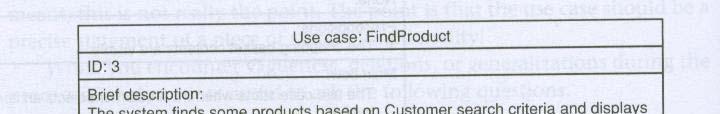
110 Eg. Generalization Usecase Find Product Sales System Customer Find Book Find CD
111 Generalization Usecase.. Use case features Inherit Add Override Relationship Y Y N Extention point Y Y N Preconditions Y Y Y Postcondition Y Y Y Step in main flow Y Y Y Alternative flow y Y Y
112 Generalization Usecase Simple tag conventions are Inherited without change-3.(3.) Inherited and renumbered- 6.2(6.1) Inherited and overridden- 1.(01.) Inherited, overridden and renumbered- 5.2(o5.1) Added
113 Usecase Dependencies Extend and Include relationships between use cases Shown as stereotyped dependencies Stereotypes are written as text strings in guillemots: «extend» «include»
114 <<Include>> used to separate out a sequence of behaviour that is used in more than one use cases Including usecase is the base usecase Included usecase is the inclusion usecase Base usecase is not complete without inclusion Inclusion may be complete/ incomplete
115 Include Usually not complete View Balance «include» Select Account Client Withdraw «include» May be complete or not Usually not complete
116 Extend One use case provides additional functionality that may be required in another use case Base usecase is generally complete without the insertion segment Extension points are generally not complete
117 Eg. Extend Need not to show the extention points always Extension point Usually complete View Balance displays balance ATM Client user requires print-out Print Balance «extend» Usually not complete
118 Use case Modeling most Applicability Usecase modeling is most appropriate for system that Dominated by functional requirements Have many types of users Have many interfaces to other systems
119 Use case Modeling least Applicability Dominated by non-functional requirements Have few users Have few interfaces
120 Use of Advance Features Actor generalization- Only where it simplifies the model Use case generalization i Consider not using, or only using with abstract parents <<include>> Where it simplifies model Beware of overuse, as it makes functional decomposition <<extend>> Use carefully to ensure all stakeholder exposed to the model understand and agree on its semantics
121 Hints to Write Use Case Keep use case short and simple Focus on the what not the how Avoid functional decomposition
122 The project glossary Important project artifact Project Glossary Provides a dictionary of key business terms Captures business language and jargon Should resolve synonyms and homonyms Should be understandable by all stakeholders UML does not set a standard for the project glossary Synchronization between the project glossary and the UML model is needed
123 Requirements Tracing
124 Putting the UML to Work The ESU University wants to computerize their registration system The Registrar sets up the curriculum for a semester One course may have multiple course offerings Students select 4 primary courses and 2 alternate courses Once a student registers for a semester, the billing system is notified so the student may be billed for the semester Students may use the system to add/drop courses for a period of time after registration Professors use the system to receive their course offering rosters Users of the registration system are assigned passwords which are used at logon validation Copyright 1997 by Rational Software Corporation
125 System Boundary Semester curriculum Student registration for semester
126 Actors-ESU Registrar Professor Student Billing System
127 ESU-Use Cases Actors are examined to determine their needs Registrar -- maintain the curriculum Professor -- request roster Student -- maintain schedule Billing System -- receive e billing information ato from registration Maintain Curriculum Request Course Roster Maintain Schedule Copyright 1997 by Rational Software Corporation
128 Use Case Diagram Student Maintain Schedule Request Course Roster Professor Billing System Maintain Curriculum Registrar Copyright 1997 by Rational Software Corporation
129 Use case-maintain Curriculum.. ID:2 Brief Description: Registrar setup curriculum for semester Primary Actors: Registrar Secondary Actors: None Precondition: 1. Registrar logs onto the Registration System
130 Use case-maintain Curriculum.. Main Flow: 1. prompts the Registrar to select the current semester or a future semester 2. The Registrar enters the desired semester 3.system prompts the registrar to select the desired activity: it ADD, DELETE, REVIEW, or QUIT 4.If the activity selected is ADD 5.1 Add a Course subflow is performed 5. If the activity selected is DELETE 5.1 Delete a Course subflow is performed. 6. If the activity selected is REVIEW 6.1 Review Curriculum subflow is performed. 7. If the activity selected is QUIT 7.1 the use case ends.
131 Use case-maintain Curriculum Post conditions: None Alternative Flow: None
132 Use Case Diagram View Report Card Login Student Register for Courses Select Courses to Teach Course Catalog User Professor Submit Grades Registrar Maintain Professor Information Maintain Carriculum Maintain Student Information Close Registration Billing System
133 Activity Diagrams modeling the logic captured by a single use case or usage scenario, or for modeling the detailed logic of a business rule Bharati Vidyapeeth s Institute of Computer Applications and Management, New Delhi-63, by Anukiran Jian
134 Learning Objectives Activity diagram concept Elements of activity diagram Reading activity diagrams Process logic in activity diagram Creating activity diagrams Case Study
135 Activity Diagram (AD) Concept AD used for requirements determination AD depicts: process (workflow) manual & automated process logic time order of process steps (activities) & decision points process performers AD resembles old flow charts and somewhat data flow diagram


;")


136 AD elements Quote process Start Time * Who/What performs activity Swimline Activity, Process step Process flow Decision point (System s logic); End Choices (yes/no); activity branching * System=computer, computer software and hardware; same as in use case descriptions

")


137 AD elements (cont.) Synchronization Bar Parallel processes Synchronization Bar


138 Telephone Order Process simpler (cont.)
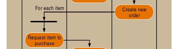
139 Process Logic Sequential (step 1 step 2) Conditional, If-Then (decision points: if condition A, then step n) Iteration, loops (feedback into a previous step while certain condition persists Slide 145, feedback from the Change required? decision point) Slide 147, loop between bars For each item to End of each
140 Data passed between steps What AD does not Show? Objects (directly, can be inferred) User interface
141 How to Create AD 1. Identify activities (steps) of a process 2. Identify who/what performs activities (process steps) 3. Draw swimlines 4. Identify decision i points (if-then) 5. Determine if step is in loop (For each, if-then based loop) 6. Determine if step is parallel 7. Identify order of activities, decision points Continues
142 How to create AD (cont.) 8. Draw the start point of the process in the swimline of the first activity (step) 9. Draw the oval of the first activity (step) 10. Draw an arrow to the location of the second activity 11. Draw subsequent activities, while inserting decision points and synchronization/loop bars where appropriate 12. Draw the end point after the last activity. You can tabulate this information (see next slide).
143 How to Create AD (cont.) 1 St ep ID Process Step (Activity, D i i ) Who/Wha t Performs St Parall el Activi ty Loo p Prec e- ding St Decision) Step ty Step 2 1 Request quote Customer No No Develop requirement notes 3 Decision: Help? Salespers on No Yes 1 3 Decision: Salespers - Yes 2 on 4 Salesperso n enters data Salespers on No Yes 3 5 Check requirement s Technical Expert No Yes 3
 1 8 4 2 3 St ep Process Step")


144 How to Create AD (cont.) St ep Process Step Who/Wha t Parall el Loo p Prec e- ID (Activity, it Performs Activi ding Decision) Step ty Step 6 Tech. expert Technical No Yes 5 5 enters data Expert 7 Calculate System No Yes 4, 6 6 quote 8 Review Customer No Yes 7 7 quote Decision: Changes? Customer No Yes 8 10 Accept quote as order Customer No No 9
145 Case Study - Agate Ltd; B,M&F-85 Agate is an advertising company Many companies are its clients Clients have advertising campaigns Each campaign includes one or more adverts Staff may work on several campaigns at a time Bonus is calculated depending on salary grade Tom Farmers WareHouse Fathers Day Red-hot
146 Drawing Activity Diagrams Identify activities What happens when a new client is added in the Agate system? Add a New Client Assign Staff Contact Add New Campaign Assign Staff to Campaign Organise the activities in order with transitions
147 Drawing Activity Diagrams.. Add a New Client Assign Staff Contact t Add New Campaign Assign Staff to Campaign
148 Drawing Activity Diagrams.. Identify any alternative transitions and the conditions on them sometimes there is a new campaign to add for a new client, sometimes not sometimes they will want to assign staff to the campaign, sometimes not Add transitions and guard conditions to the diagram
149 Drawing Activity Diagrams.. Add a New Client Assign Staff Contact [no campaign to add] [campaign to add] Add New Campaign [no staff to assign] [staff to assign] Assign Staff to Campaign
150 Drawing Activity Diagrams.. Identify any processes that are repeated they will want to assign staff to the campaign until there are no more staff to add Add transitions and guard conditions to the diagram
151 Drawing Activity Diagrams.. Add a New Client Assign Staff Contact [no campaign to add] [campaign to add] Add New Campaign [no staff to assign] [staff to assign] [no more staff to assign] Assign Staff to Campaign [more staff to assign]
152 Drawing Activity Diagrams.. Are all the activities carried out by the same person, organisation or department? If not, then add swim lanes to show the responsibilities Name the swim lanes Show each activity in the appropriate swim lane
153 Drawing Activity Diagrams.. Administrator Campaign Manager Add a New Client Assign Staff Contact [no campaign to add] [campaign to add] Add New Campaign [no staff to assign] [staff to assign] Assign Staff to Campaign
154 Drawing Activity Diagrams.. Are there any object flows and objects to show? these can be documents that are created or updated in a business activity diagram these can be object instances that change state in an operation or a use case Add the object flows and objects
155 Drawing Activity Diagrams.. Administrator Campaign Manager Add a New Client :Client [New] Assign Staff Contact [no campaign to add] :Campaign [Commissioned] Add New Campaign [campaign to add] [no staff to assign] [staff to assign] Assign Staff to Campaign
156 Exercise Create an activity diagram based on the following narrative. The purchasing department handles purchase requests from other departments in the company. People in the company who initiate the original purchase request are the "customers" of the purchasing department. A case worker within the purchasing department receives that request and monitors it until it is ordered and received. Case workers process pocessthe requests for purchasing products under $1,500, write a purchase order, and then send it to the approved vendor. Purchase requests over $1,500 must first be sent out for a bid from the vendor that supplies the product. When the bids return, the case worker selects one bid. Then, the case worker writes a purchase order and sends it to the approved vendor
157 Exercise Develop an activity diagram based on the following narrative. The purpose of the Open Access Insurance System is to provide automotive insurance to car owners. Initially, prospective customers fill out an insurance application, which provides information about the customer and his or her vehicles. This information is sent to an agent, who sends it to various insurance companies to get quotes for insurance. When the responses return, the agent then determines the best policy for the type and level of coverage desired and gives the customer a copy of the insurance policy proposal and quote.
158 Sequence Diagram

159 Interaction Diagrams UML Specifies a number of interaction diagrams to model dynamic aspects of the system Dynamic aspects of the system Messages moving among objects/ classes Flow of control among objects Sequences of events
160 Dynamic Diagram Types Interaction Diagrams - Set of objects or roles and the messages that can be passed among them. Sequence Diagrams - emphasize time ordering Communication Diagrams - emphasize structural ordering State Diagrams State machine consisting of states, transitions, events and activities of an object Activity & Swimlane Diagrams Emphasize and show flow of control among objects
161 Sequence Diagrams Describe the flow of messages, events, actions between objects Show concurrent processes and activations Show time sequences that are not easily depicted in other diagrams Typically used during analysis and design to document and understand the logical flow of your system Emphasis s on time ordering!
162 Sequence Diagram
163 Sequence Diagram Time Increasing --> All lines should be horizontal to indicate instantaneous actions. Additionally if ActivityA happens before ActivityB, ActivityA must be above activity A
 Time=B What does this mean?")
164 Diagonal Lines :Student :Registratio n System Time=A GetDetails() Time=B What does this mean? Do you typically care?
165 Components Objects: astudent is a specific instance of the Student class Specific Instance of an Object Generic (unnamed) objects Generic (unnamed) objects of class type Seminar and Course

166 Components lifeline execution
167 Components Method call Return value
168 Components c : Client create() : Transaction o : ODBCProxy setactions(a, b, c) setvalues(a, 3, 4) setvalues(b, c, 7) (committed) destroy() create() destroy() Synchronous message Asynchronous message Return message
169 Async Message Example Synchronous message Asynchronous message Return message
170 Components: alt/else
171 Components: option
172 Components: loop
173 Rules of thumb Rarely use options,loops,alt/else These constructs complicate a diagram and make them hard to read/interpret. Frequently it is better to create multiple simple diagrams Create sequence diagrams for use cases when it helps clarify and visualize a complex flow Remember: the goal of UML is communication and understanding
174 Summary Sequence diagrams model object interactions with an emphasis on time ordering Method call lines Must be horizontal! Vertical height matters! Lower equals Later Label the lines Lifeline dotted vertical line Execution bar bar around lifeline when code is running Arrows Synchronous call (you re waiting for a return value) triangle arrow-head Asynchronous call (not waiting for a return) open arrow-head Return call dashed line
175 Internet shop PlaceOrder Usecase The customer opens an order form in his/her web browser and selects a product as well as the amount he/she wants to buy. The customer submits the form. The system will send an order confirmation via to the customer. The system will check the magazine, to see if the requested amount is on stock. If this is the case, the order is shipped immediately. Otherwise The system orders the missing goods via from a major supplier. If parts of the ordered goods are on stock, they are reserved for that order. The system adds the order to the list of open orders. Draw a sequence diagram for this use case.
176 In class exercise Draw a sequence diagram for: Adding a picture to Flickr (or any online image database). Login, pick an album, upload a picture, etc Think about the software classes that would be involved WebGUI (think of this as reporting what the user does), UserAccount, Album, AlbumList, etc Don t forget to check and update their current disk usage. For this diagram show the check coming back as acceptable.. you would do a second diagram for them running over quota.
177 Class & Object Diagram Bharati Vidyapeeth s Institute of Computer Applications and Management, New Delhi-63, by Anukiran Jian
178 Class Diagrams UML modeling elements in class diagrams Classes and their structure and behavior Association, dependency, and inheritance relationships Multiplicity and navigation indicators Role names
179 Classes A class is a collection of objects with common structure common behavior common relationships common semantics Classes are found by examining the objects in sequence and collaboration diagram A class is drawn as a rectangle with three compartments Classes should be named using the vocabulary of the domain Naming standards should be created e.g., all classes are singular nouns starting with a capital letter
180 Operations The behavior of a class is represented by its operations Operations may be found by examining interaction diagrams RegistrationManager addcourse(student,course)
181 Attributes The structure of a class is represented by its attributes Attributes may be found by examining class definitions, the problem requirements, and by applying domain knowledge Syntax visibility name: type multiplicity = default {property-string} p {+,-, {Integer, {[1], {0, { readonly, } Boolean, [n] foo, ordered, String, [0..1], , nonunique, Date, [m..n], 100, unique, Money, [*], } bag, } [1..*], set [n..*]} } Each course offering has a number, location and time CourseOffering number location time
182 Attributes Structural Features An attribute describes a property as a line of text within the class box Syntax visibility name: type multiplicity = default {property-string} {+,-, {Integer, {[1], {0, { readonly, #,`} Boolean, [n] foo, ordered, String, [0..1], , nonunique, Date, [m..n], 100, unique, Money, [*], } bag, } [1..*], set [n..*]} }
183 Relationships Relationships provide a pathway for communication between objects if two objects need to talk there must be a link between them Three types of relationships are: Generalization Association Dependency
184 Associations (structural features) An association is a bi-directional connection between classes An association is shown as a line connecting the related classes Source property name mul mul Target Example Person 1 cars * Car
185 Multiplicity Notation 1 * 0..1 m..n {ordered} * Class Class Class Class Class exactly one many (zero or more) optional (zero or more) numerically specified ordered
186 Order = class fields datareceived: Data isprepaid: Boolean * 1 Order Customer number: String 1 price: Money customer: Customer lineitems: List<Order Line> * {ordered} methods Order Line dispatch close
187 Putting the UML to Work The ESU University wants to computerize their registration system The Registrar sets up the curriculum for a semester One course may have multiple course offerings Students select 4 primary courses and 2 alternate courses Once a student registers for a semester, the billing system is notified so the student may be billed for the semester Students may use the system to add/drop courses for a period of time after registration Professors use the system to receive their course offering rosters Users of the registration system are assigned passwords which are used at logon validation
188 Classes RegistrationForm Schedule Agorithm RegistrationManager Course Student Professor Course Offering Copyright 1997 by Rational Software Corporation
189 Operations & Attributes RegistrationForm RegistrationManager g ScheduleAlgorithm addstudent(course, StudentInfo) Professor name tenurestatus Student name major Course name numbercredits open() addstudent(studentinfo) CourseOffering location open() addstudent(studentinfo) d t(st d ti
190 Relationship RegistrationForm RegistrationManager g ScheduleAlgorithm addstudent(course, StudentInfo) Professor name tenurestatus Student name major Course name numbercredits open() addstudent(studentinfo) CourseOffering location open() addstudent(studentinfo) d t(st d ti
191 Generalization RegistrationForm RegistrationManager g ScheduleAlgorithm addstudent(course, StudentInfo) Professor name tenurestatus Student name major Course name numbercredits open() addstudent(studentinfo) CourseOffering location open() addstudent(studentinfo) d t(st d ti
192 Object Diagrams An object diagram is a snapshot of the objects in the system Useful for showing complex structures Object names are underlined Syntax instance name : class name instance name :class name
193 Case Study Dog Fun Each customer has one or more dogs I keep track of the customers kind of dogs and so I can send them greetings at Christmas and new offers [if they want]. Ialsokeep track of how much they have spent The system helps me compute how much the customer should pay for the treatments of the dogs the customer brings A treatment starts with a wash that has a fixed cost of 10$ no matter what kind of dog
194 Dog Fun.. Then there are three kinds of ways to continue a treatment: 1. puddle-cut which h can be NY-style tl to $100 or London to $50 (London style may include coloring for an extra $10) [I decline to puddle cut a dog that s not a puddle] 2. trim-cut for $30, or 3. style-cut for $40 Some of my costumers get a discount of some percent, but not all
195 State Diagram Bharati Vidyapeeth s Institute of Computer Applications and Management, New Delhi-63, by Anukiran Jian
196 Terms & Def. State Diagram shows state Machine State Machine is a behaviour that specifies the sequence of states an object goes through during its life time in response to event State is a condition or situation in the life of an object during which It satisfies certain condition Perform some activities Or wait for some event
197 Terms & Def. event is the specification of a significant occurrence that has a location in time & space In context to state machine An event is an occurrence of a stimulus that can trigger a state transition Transition is a relationship between two states An activity specifies non atomic on going execution
198 Terms & Def. Types of events External Signals Call Events Internal Change Event Time Event
199 State Diagrams A state diagram is a graph whose nodes are states and whose directed arcs are transitions between states. t A state diagram specifies the state sequences caused by event sequences. State names must be unique within the scope of a state diagram. All objects in a class execute the state diagram for that class, which models their common behavior.
200 Purpose To model dynamic aspect of a system. To model life time of a reactive system. To describe different states of an object during its life time. Define a state machine to model states of an object.
201 Where to use To model object states of a system. To model reactive system. Reactive system consists of reactive objects. To identify events responsible for state changes. Forward and reverse engineering.

202 Here s a simple example STD for a washing machine. State Transition Condition Action
203 A condition is typically some kind of event, e.g.: Signal Arrival of an object (data/material), Etc An action is the appropriate it output tor response to the event, e.g.: Signal or message Transfer of an object, Calculation, Condition Etc Action
204 Here s an even more interesting example. It is now perfectly clear that you: Can go right ihto rinsing i without ih washing, but.. Can never go to spin drying without rinsing. So, what would I use such a modeling technique for?
205 State Transition Matrix From State 1 State 2 State 3 etc To State 1 State 2 State 3 etc Condition Action Condition Action
206 State Transitions Matrix From Idle Washing Rinsing Spin Drying To Idle Spin dry cycle complete Sound buzzer Do this first to define desired operation. Check blank cells have we covered all possible desired transitions? Washing Rinsing Spin Drying Wash signal Start wash cycle Rinse signal Wash cycle complete Start rinse cycle Start rinse cycle Rinse cycle complete Start Spin dry cycle
207 Basic State Diagram Notation State diagram name State1 entry/ action do / activity exit/ action event (attribs) [condition]/effect State2..
208 Do-Activities an activity that continues for an extended time. can only occur within a state and cannot be attached to a transition. include continuous operations, such as displaying a picture on a television screen Sequential operations that terminate by themselves after an interval of time such as closing a valve.
209 Do-Activities may be performed for all or part of the duration thatt an object is in a state. may be interrupted by an event that is received during its execution such an event may or may not cause a transition out of the state containing the do-activity. Paper jam do/flash warning light
210 Entry and Exit Activities As an alternative to showing activities on transitions, The next figure shows the control of a garage door opener. depress / motor up Opening Closed depress / motor up door open / motor off Open door closed / motor off Closing depress / motor down
211 Activities on entry to states Opening depress Closed entry / motor off entry / motor up depress door open Open entry / motor off door closed depress Closing entry / motor down
212 Exit Activity less common than entry activities, iti but they are occasionally useful. Whenever the state is exited, by any outgoing transition, the exit activity is performed first. If a state has multiple activities, they are performed in the following order: activities on the incoming transition, entry activities, doactivities, exit activities, activities on the outgoing transition. Events that cause transitions out of the state can interrupt do- activities. If a do-activity is interrupted, the exit activity is still performed. In general, any event can occur within a state and cause an activity to be performed. Entry and exit are only two examples of events that can occur.
213 One shot State Diagram Chess White s turn checkmate Black wins black moves white moves stalemate stalemate Draw Black s turn checkmate White wins

214 State Diagram for a Phone Line 229
215 Composite State Concept of substate
216 Substates Substates Orthogonal (concurrently active) Nonorthogonal (Sequential active)
217 State Diagram in UML..
218 State Diagram in UML..
219 Concurrent States Transitions to and from Concurrent States multiple source states and target states
220 Concurrent States
221 History States
222 Problem # 1 A simple digital watch has a display and two buttons to set it, the A button and the B button. The watch has two modes of operation, display time and set time. In the display time mode, the watch displays hours and minutes, separated by a flashing colon. The set time mode has two submodes, set hours and set minutes. The A button selects modes. Each time it is pressed, the mode advances in the sequence: display, set hours, set minutes, display, etc. Within the submodes, the B button advances the hours or minutes once each time it is pressed. Buttons must be released before they can generate another event. Prepare a state diagram of the watch.
223 Component & Deployment Diagram Bharati Vidyapeeth s Institute of Computer Applications and Management, New Delhi-63, by Anukiran Jian
224 Component Diagram Component Diagram: High-Level Interaction Dependencies Among Software Components Captures the Physical Structure of the Implementation Built As Part of Architectural Specification Purposes: Organize Source Code Construct an Executable Release Specify a Physical Database Main Concepts: Component, Interface, Dependency, Realization Developed by Architects and Programmers
225 Component Diagram Captures the Physical Structure of the Implementation
226 Deployment Diagram Deployment Diagram: Focus on the Placement and Configuration of Components at Runtime Captures the Topology of a System s Hardware Built As Part of Architectural Specification Purposes: Specify the Distribution of Components Identify Performance Bottlenecks Main Concepts: Node, Component, Dependency, Location Developed by Architects, Networking Engineers, and System Engineers

227 Deployment Diagram Captures the Topology of a System s Hardware
228 UNIT IV Learning s Modeling with UML Basic Building Blocks of UML A Conceptual Model of UML Basic Structural Modeling UML Diagrams Case Studies


229 Objective Questions Q1. The arrow in the above diagram indicate 1. Refers to 2. Association 3. Dependency 4. Navigability Q2. At Conceptual level, a Class can consist attributes of: a. Primitive data type b. Value object data type e.g. Date, Money c. Complex data type e.g. Customer, Account, Inventory d. e. All of the above A, b ONLY f. A, c ONLY
Analysis and Design with UML
 Analysis and Design with UML Page 1 Agenda Benefits of Visual Modeling History of the UML Visual Modeling with UML The Rational Iterative Development Process Page 2 What is Visual Modeling? Item Order
Sequence Diagrams. Dan Fleck. Coming up: Interaction Diagrams
 Sequence Diagrams Dan Fleck Coming up: Interaction Diagrams Coming up: Dynamic Diagram Types Interaction Diagrams UML Specifies a number of interaction diagrams to model dynamic aspects of the system Dynamic
What is use case modeling? 10 - UML Overview. Use-Case diagrams CMPSCI520/620. Rick Adrion 2003 (except where noted) 1
 1") What is use case modeling? 10 - UML Overview use case model a view of a system that emphasizes the behavior as it appears to outside users. A use case model partitions system functionality into transactions
What is use case modeling? 10 - UML Overview use case model a view of a system that emphasizes the behavior as it appears to outside users. A use case model partitions system functionality into transactions
OO Analysis and Design with UML 2 and UP
 OO Analysis and Design with UML 2 and UP Dr. Jim Arlow, Zuhlke Engineering Limited Clear View Training 2008 v2.5 1 UML principles Clear View Training 2008 v2.5 2 1.2 What is UML? Unified Modelling Language
Interactions A link message
 Interactions An interaction is a behavior that is composed of a set of messages exchanged among a set of objects within a context to accomplish a purpose. A message specifies the communication between
Software Engineering from a
 Software Engineering from a modeling perspective Robert B. France Dept. of Computer Science Colorado State University USA france@cs.colostate.edu Softwaredevelopment problems Little or no prior planning
Advanced Software Engineering
 Dev Bhoomi Institute Of Technology LABORATORY MANUAL PRACTICAL INSTRUCTION SHEET EXPERIMENT NO. ISSUE NO. : ISSUE DATE: REV. NO. : REV. DATE : PAGE: 1 LABORATORY Name & Code: Advanced Software Engineering
Chapter 10. Object-Oriented Analysis and Modeling Using the UML. McGraw-Hill/Irwin
 Chapter 10 Object-Oriented Analysis and Modeling Using the UML McGraw-Hill/Irwin Copyright 2007 by The McGraw-Hill Companies, Inc. All rights reserved. Objectives 10-2 Define object modeling and explain
Software Service Engineering
 Software Service Engineering Lecture 4: Unified Modeling Language Doctor Guangyu Gao Some contents and notes selected from Fowler, M. UML Distilled, 3rd edition. Addison-Wesley Unified Modeling Language
Topics. Overview- The UML Functional Model. Structural Model. Behavioral Models. Use Case Diagram (essential and system)
") Topics Overview- The UML Functional Model Use Case Diagram (essential and system) Structural Model Class/object, Component and Deployment Diagram Behavioral Models Activity, State chart, sequence /collaboration
Topics Overview- The UML Functional Model Use Case Diagram (essential and system) Structural Model Class/object, Component and Deployment Diagram Behavioral Models Activity, State chart, sequence /collaboration
MAHARASHTRA STATE BOARD OF TECHNICAL EDUCATION (Autonomous) (ISO/IEC Certified)
 (ISO/IEC Certified)") Important Instructions to examiners: 1) The answers should be examined by key words and not as word-to-word as given in the model answer scheme. 2) The model answer and the answer written by candidate
Important Instructions to examiners: 1) The answers should be examined by key words and not as word-to-word as given in the model answer scheme. 2) The model answer and the answer written by candidate
Architecture and the UML
 Architecture and the UML Models, Views, and A model is a complete description of a system from a particular perspective Use Case Use Case Sequence Use Case Use Case Use Case State State Class State State
LABORATORY 1 REVISION
 UTCN Computer Science Department Software Design 2012/2013 LABORATORY 1 REVISION ================================================================== I. UML Revision This section focuses on reviewing the
UNIT II. Syllabus. a. An Overview of the UML: Visualizing, Specifying, Constructing, Documenting
 UNIT II Syllabus Introduction to UML (08 Hrs, 16 Marks) a. An Overview of the UML: Visualizing, Specifying, Constructing, Documenting b. Background, UML Basics c. Introducing UML 2.0 A Conceptual Model
SOFTWARE DESIGN COSC 4353 / Dr. Raj Singh
 SOFTWARE DESIGN COSC 4353 / 6353 Dr. Raj Singh UML - History 2 The Unified Modeling Language (UML) is a general purpose modeling language designed to provide a standard way to visualize the design of a
Index. Add Diagram > Sequence Diagram command,
 Quatrani.book Page 183 Monday, May 8, 2006 11:56 AM Index A abstraction, 3 actions completing before processing, 54 55 data flowing through, 53 passing control between, 51 performing, 155 157 as round-cornered
A - 1. CS 494 Object-Oriented Analysis & Design. UML Class Models. Overview. Class Model Perspectives (cont d) Developing Class Models
 Developing Class Models") CS 494 Object-Oriented Analysis & Design UML Class Models Overview How class models are used? Perspectives Classes: attributes and operations Associations Multiplicity Generalization and Inheritance Aggregation
CS 494 Object-Oriented Analysis & Design UML Class Models Overview How class models are used? Perspectives Classes: attributes and operations Associations Multiplicity Generalization and Inheritance Aggregation
MAHARASHTRA STATE BOARD OF TECHNICAL EDUCATION (Autonomous) (ISO/IEC Certified) MODEL ANSWER
 (ISO/IEC Certified) MODEL ANSWER") Important Instructions to examiners: 1) The answers should be examined by key words and not as word-to-word as given in the model answer scheme. 2) The model answer and the answer written by candidate
Important Instructions to examiners: 1) The answers should be examined by key words and not as word-to-word as given in the model answer scheme. 2) The model answer and the answer written by candidate
UML Fundamental. OutLine. NetFusion Tech. Co., Ltd. Jack Lee. Use-case diagram Class diagram Sequence diagram
 UML Fundamental NetFusion Tech. Co., Ltd. Jack Lee 2008/4/7 1 Use-case diagram Class diagram Sequence diagram OutLine Communication diagram State machine Activity diagram 2 1 What is UML? Unified Modeling
IS 0020 Program Design and Software Tools
 1 IS 0020 Program Design and Software Tools Unified Modeling Language Lecture 13 April 13, 2005 What is UML? 2 The Unified Modelling Language is a standard notation to model [object oriented] systems.
Lesson 11. W.C.Udwela Department of Mathematics & Computer Science
 Lesson 11 INTRODUCING UML W.C.Udwela Department of Mathematics & Computer Science Why we model? Central part of all the activities We build model to Communicate Visualize and control Better understand
Lab Manual. Object Oriented Analysis And Design. TE(Computer) VI semester
 VI semester") Lab Manual Object Oriented Analysis And Design TE(Computer) VI semester Index Sr. No. Title of Programming Assignment Page No. 1 2 3 4 5 6 7 8 9 10 Study of Use Case Diagram Study of Activity Diagram Study
Lab Manual Object Oriented Analysis And Design TE(Computer) VI semester Index Sr. No. Title of Programming Assignment Page No. 1 2 3 4 5 6 7 8 9 10 Study of Use Case Diagram Study of Activity Diagram Study
Software Engineering Lab Manual
 Kingdom of Saudi Arabia Ministry Education Prince Sattam Bin Abdulaziz University College of Computer Engineering and Sciences Department of Computer Science Software Engineering Lab Manual 1 Background:-
UNIT I. 3. Write a short notes on process view of 4+1 architecture. 4. Why is object-oriented approach superior to procedural approach?
 Department: Information Technology Questions Bank Class: B.E. (I.T) Prof. Bhujbal Dnyaneshwar K. Subject: Object Oriented Modeling & Design dnyanesh.bhujbal11@gmail.com ------------------------------------------------------------------------------------------------------------
INTRODUCTION TO UNIFIED MODELING MODEL (UML) & DFD. Slides by: Shree Jaswal
 & DFD. Slides by: Shree Jaswal") INTRODUCTION TO UNIFIED MODELING MODEL (UML) & DFD Slides by: Shree Jaswal What is UML? 2 It is a standard graphical language for modeling object oriented software. It was developed in mid 90 s by collaborative
INTRODUCTION TO UNIFIED MODELING MODEL (UML) & DFD Slides by: Shree Jaswal What is UML? 2 It is a standard graphical language for modeling object oriented software. It was developed in mid 90 s by collaborative
Allenhouse Institute of Technology (UPTU Code : 505) OOT Notes By Hammad Lari for B.Tech CSE V th Sem
 OOT Notes By Hammad Lari for B.Tech CSE V th Sem") UNIT-1 ECS-503 Object Oriented Techniques Part-1: Object-Oriented Programming Concepts What Is an Object? Objects are key to understanding object-oriented technology. Look around right now and you'll find
UNIT-1 ECS-503 Object Oriented Techniques Part-1: Object-Oriented Programming Concepts What Is an Object? Objects are key to understanding object-oriented technology. Look around right now and you'll find
Oral Questions. Unit-1 Concepts. Oral Question/Assignment/Gate Question with Answer
 Unit-1 Concepts Oral Question/Assignment/Gate Question with Answer The Meta-Object Facility (MOF) is an Object Management Group (OMG) standard for model-driven engineering Object Management Group (OMG)
Object Oriented Design. Program Design. Analysis Phase. Part 2. Analysis Design Implementation. Functional Specification
 Object Oriented Design Part 2 Analysis Design Implementation Program Design Analysis Phase Functional Specification Completely defines tasks to be solved Free from internal contradictions Readable both
Object Oriented Modeling
 Overview UML Unified Modeling Language What is Modeling? What is UML? A brief history of UML Understanding the basics of UML UML diagrams UML Modeling tools 2 Modeling Object Oriented Modeling Describing
Introduction to UML. Danang Wahyu utomo
 Introduction to UML Danang Wahyu utomo danang.wu@dsn.dinus.ac.id 085 740 955 623 Evolution of OO Development Methods History of OOAD leading to UML Why Model? Analyse the problem domain - Simplify reality
Vidyalankar. T.Y. Diploma : Sem. VI [IF/CM] Object Oriented Modeling and Design Prelim Question Paper Solution
![Vidyalankar. T.Y. Diploma : Sem. VI [IF/CM] Object Oriented Modeling and Design Prelim Question Paper Solution](/thumbs/86/94007497.jpg "Vidyalankar. T.Y. Diploma : Sem. VI [IF/CM] Object Oriented Modeling and Design Prelim Question Paper Solution") T.Y. Diploma : Sem. VI [IF/CM] Object Oriented Modeling and Design Prelim Question Paper Solution Q.1(a) Attempt any THREE of the following [12] Q.1(a) (i) What is modeling? Also state its four features.
T.Y. Diploma : Sem. VI [IF/CM] Object Oriented Modeling and Design Prelim Question Paper Solution Q.1(a) Attempt any THREE of the following [12] Q.1(a) (i) What is modeling? Also state its four features.
UNIT-I Introduction of Object Oriented Modeling
 UNIT-I Introduction of Object Oriented Modeling - Prasad Mahale Object Oriented Modeling and Reference Books: Design 1. Grady Booch, James Rumbaugh, Ivar Jacobson Unified Modeling Language User Guide,
MAHARASHTRA STATE BOARD OF TECHNICAL EDUCATION (Autonomous) (ISO/IEC Certified)
 (ISO/IEC Certified)") Subject Code: 17630 Model Answer Page No: 1 /32 Important Instructions to examiners: 1) The answers should be examined by keywords and not as word-to-word as given in the model answer scheme. 2) The model
Subject Code: 17630 Model Answer Page No: 1 /32 Important Instructions to examiners: 1) The answers should be examined by keywords and not as word-to-word as given in the model answer scheme. 2) The model
Practical UML : A Hands-On Introduction for Developers
 Borland.com Borland Developer Network Borland Support Center Borland University Worldwide Sites Login My Account Help Search Practical UML : A Hands-On Introduction for Developers - by Randy Miller Rating:
Object-Oriented Systems Development: Using the Unified Modeling Language
 Object-Oriented Systems Development: Using the Unified Modeling Language Chapter 5: Unified Modeling Language Goals Modeling. Unified modeling language. Class diagram. Use case diagram. Interaction diagrams.
UML- a Brief Look UML and the Process
 UML- a Brief Look UML grew out of great variety of ways Design and develop object-oriented models and designs By mid 1990s Number of credible approaches reduced to three Work further developed and refined
Practical UML - A Hands-On Introduction for Developers
 Practical UML - A Hands-On Introduction for Developers By: Randy Miller (http://gp.codegear.com/authors/edit/661.aspx) Abstract: This tutorial provides a quick introduction to the Unified Modeling Language
Unified Modeling Language (UML)
") 1 / 45 Unified Modeling Language (UML) Miaoqing Huang University of Arkansas 2 / 45 Outline 1 Introduction 2 Use Case Diagram 3 Class Diagram 4 Sequence Diagram 3 / 45 Outline 1 Introduction 2 Use Case
1 / 45 Unified Modeling Language (UML) Miaoqing Huang University of Arkansas 2 / 45 Outline 1 Introduction 2 Use Case Diagram 3 Class Diagram 4 Sequence Diagram 3 / 45 Outline 1 Introduction 2 Use Case
Chapter 5: Structural Modeling
 Chapter 5: Structural Modeling Objectives Understand the rules and style guidelines for creating CRC cards, class diagrams, and object diagrams. Understand the processes used to create CRC cards, class
Object-Oriented Systems Analysis and Design Using UML
 10 Object-Oriented Systems Analysis and Design Using UML Systems Analysis and Design, 8e Kendall & Kendall Copyright 2011 Pearson Education, Inc. Publishing as Prentice Hall Learning Objectives Understand
Introduction to UML Dr. Rajivkumar S. Mente
 Introduction to UML Dr. Rajivkumar S. Mente Assistant Professor, Department of Computer Science, Solapur University, Solapur rajivmente@rediffmail.com Introduction to UML UML is a language used for 1.
UNIT-4 Behavioral Diagrams
 UNIT-4 Behavioral Diagrams P. P. Mahale Behavioral Diagrams Use Case Diagram high-level behaviors of the system, user goals, external entities: actors Sequence Diagram focus on time ordering of messages
Basic Structural Modeling. Copyright Joey Paquet,
 Basic Structural Modeling Copyright Joey Paquet, 2000 1 Part I Classes Copyright Joey Paquet, 2000 2 Classes Description of a set of objects sharing the same attributes, operations and semantics Abstraction
Meltem Özturan
 Meltem Özturan www.mis.boun.edu.tr/ozturan/samd 1 2 Modeling System Requirements Object Oriented Approach to Requirements OOA considers an IS as a set of objects that work together to carry out the function.
From Analysis to Design. LTOOD/OOAD Verified Software Systems
 From Analysis to Design 1 Use Cases: Notation Overview Actor Use case System X System boundary UCBase «extend» UCExt Actor A UCVar1 UCVar2 Extending case Generalization «include» Actor B UCIncl Included
Unified Modeling Language (UML)
") Unified Modeling Language (UML) Troy Mockenhaupt Chi-Hang ( Alex) Lin Pejman ( PJ ) Yedidsion Overview Definition History Behavior Diagrams Interaction Diagrams Structural Diagrams Tools Effect on Software
Unified Modeling Language (UML) Troy Mockenhaupt Chi-Hang ( Alex) Lin Pejman ( PJ ) Yedidsion Overview Definition History Behavior Diagrams Interaction Diagrams Structural Diagrams Tools Effect on Software
UNIT-II Introduction to UML
 UNIT-II Introduction to UML - P. P. Mahale UML OVERVIEW OF UML :- We need a Modeling Language! We will use the Unified Modeling Language, UML), Provides a standard for artifacts produced during development
Modeling with UML. (1) Use Case Diagram. (2) Class Diagram. (3) Interaction Diagram. (4) State Diagram
 Use Case Diagram. (2) Class Diagram. (3) Interaction Diagram. (4) State Diagram") Modeling with UML A language or notation intended for analyzing, describing and documenting all aspects of the object-oriented software system. UML uses graphical notations to express the design of software
Modeling with UML A language or notation intended for analyzing, describing and documenting all aspects of the object-oriented software system. UML uses graphical notations to express the design of software
Introduction to Software Engineering. 5. Modeling Objects and Classes
 Introduction to Software Engineering 5. Modeling Objects and Classes Roadmap > UML Overview > Classes, attributes and operations > UML Lines and Arrows > Parameterized Classes, Interfaces and Utilities
INTRODUCING THE UML. Chapter 2
 chap02.fm Page 13 Friday, October 27, 2000 10:26 AM Chapter 2 INTRODUCING THE UML In this chapter Overview of the UML Three steps to understanding the UML Software architecture The software development
MAHARASHTRA STATE BOARD OF TECHNICAL EDUCATION (Autonomous) (ISO/IEC Certified) MODEL ANSWER
 (ISO/IEC Certified) MODEL ANSWER") Important Instructions to examiners: 1) The answers should be examined by key words and not as word-to-word as given in the model answer scheme. 2) The model answer and the answer written by candidate
Important Instructions to examiners: 1) The answers should be examined by key words and not as word-to-word as given in the model answer scheme. 2) The model answer and the answer written by candidate
Course "Softwaretechnik" Book Chapter 2 Modeling with UML
 Course "Softwaretechnik" Book Chapter 2 Modeling with UML Lutz Prechelt, Bernd Bruegge, Allen H. Dutoit Freie Universität Berlin, Institut für Informatik http://www.inf.fu-berlin.de/inst/ag-se/ Modeling,
The Unified Modeling Language (UML)
") The Unified Modeling Language (UML) A Very Distilled Introduction to The Unified Modeling Language (UML). A quick introduction to UML is given. Thereafter, the surface of class and activity diagrams and
The Unified Modeling Language (UML) A Very Distilled Introduction to The Unified Modeling Language (UML). A quick introduction to UML is given. Thereafter, the surface of class and activity diagrams and
Dr.S.S.Riaz Ahamed Principal, Sathak Institute of Technology, Ramanathapuram,India.
 REVIEW AND ANALYSIS OF THE ISSUES OF UNIFIED MODELING LANGUAGE FOR VISUALIZING, SPECIFYING, CONSTRUCTING AND DOCUMENTING THE ARTIFACTS OF A SOFTWARE-INTENSIVE SYSTEM Dr.S.S.Riaz Ahamed Principal, Sathak
Lecture 8: Use Case -Driven Design. Where UML fits in
 Lecture 8: Use Case -Driven Design The Role of UML in the Software Process E.g. ICONIX Domain Models Use Cases 2008 Steve Easterbrook. This presentation is available free for non-commercial use with attribution
For 100% Result Oriented IGNOU Coaching and Project Training Call CPD TM : ,
 Course Code : MCS-032 Course Title : Object Oriented Analysis and Design Assignment Number : MCA (3)/032/Assign/2014-15 Assignment Marks : 100 Weightage : 25% Last Dates for Submission : 15th October,
SE 1: Software Requirements Specification and Analysis
 SE 1: Software Requirements Specification and Analysis Lecture 9: UML Class (Concept), Object, Communication Diagrams Nancy Day, Davor Svetinović http://www.student.cs.uwaterloo.ca/ cs445/winter2006 uw.cs.cs445
SEEM4570 System Design and Implementation Lecture 11 UML
 SEEM4570 System Design and Implementation Lecture 11 UML Introduction In the previous lecture, we talked about software development life cycle in a conceptual level E.g. we need to write documents, diagrams,
Introduction to Software Engineering. 6. Modeling Behaviour
 Introduction to Software Engineering 6. Modeling Behaviour Roadmap > Use Case Diagrams > Sequence Diagrams > Collaboration (Communication) Diagrams > Activity Diagrams > Statechart Diagrams Nested statecharts
Modellistica Medica. Maria Grazia Pia, INFN Genova. Scuola di Specializzazione in Fisica Sanitaria Genova Anno Accademico
 Modellistica Medica Maria Grazia Pia INFN Genova Scuola di Specializzazione in Fisica Sanitaria Genova Anno Accademico 2002-2003 Lezione 6 UML Introduction Structural diagrams Basics What is? Please explain
Class Diagrams in Analysis
 3.2 Subject/Topic/Focus: Introduction to Classes Summary: Conceptual Modeling Notation: Classes Associations: Multiplicity, Roles, Aggregation, Composition Generalization Objects Analysis Process Literature:
UML 2.0 UML 2.0. Scott Uk-Jin Lee. Division of Computer Science, College of Computing Hanyang University ERICA Campus
 UML 2.0 Division of Computer Science, College of Computing Hanyang University ERICA Campus Introduction to UML 2.0 UML Unified Modeling Language Visual language for specifying, constructing and documenting
1: Specifying Requirements with Use Case Diagrams
 Outline UML Design Supplement 1: Specifying Requirements with Use Case Diagrams Introduction Use Case Diagrams Writing Use Cases Guidelines for Effective Use Cases Slide adapted from Eran Toch s lecture
Unified Modeling Language
 Unified Modeling Language Modeling Applications using Language Mappings Programmer s Reference Manual How to use this Reference Card: The consists of a set of fundamental modeling elements which appear
UML REFERENCE SHEETS. 2013, 2014 Michael Marking; all rights reserved, including moral rights. Web site:
 UML Reference Sheets 2013, 2014 Michael Marking; all rights reserved, including moral rights. Web site: http://www.tatanka.com/ Revision Information This document was last revised 2014.03.02. The current
Object-Oriented and Classical Software Engineering
 Slide 16.1 Object-Oriented and Classical Software Engineering Seventh Edition, WCB/McGraw-Hill, 2007 Stephen R. Schach srs@vuse.vanderbilt.edu CHAPTER 16 Slide 16.2 MORE ON UML 1 Chapter Overview Slide
VISHNU INSTITUTE OF TECHNOLOGY Vishnupur, BHIMAVARAM
 VISHNU INSTITUTE OF TECHNOLOGY Vishnupur, BHIMAVARAM 534 202 LABORATORY MANUAL IV B.Tech I Sem CSE Unified Modeling Language & Design Patterns Lab DEPARTMENT OF CSE OUR MISSION LEARN TO EXCEL Regd.No
Enterprise Architect. User Guide Series. UML Models. Author: Sparx Systems. Date: 30/06/2017. Version: 1.0 CREATED WITH
 Enterprise Architect User Guide Series UML Models Author: Sparx Systems Date: 30/06/2017 Version: 1.0 CREATED WITH Table of Contents UML Models UML Diagrams UML Structural Models Class Diagram Composite
UNIT-IV BASIC BEHAVIORAL MODELING-I
 UNIT-IV BASIC BEHAVIORAL MODELING-I CONTENTS 1. Interactions Terms and Concepts Modeling Techniques 2. Interaction Diagrams Terms and Concepts Modeling Techniques Interactions: Terms and Concepts: An interaction
Chapter No. 2 Class modeling CO:-Sketch Class,object models using fundamental relationships Contents 2.1 Object and Class Concepts (12M) Objects,
 Objects,") Chapter No. 2 Class modeling CO:-Sketch Class,object models using fundamental relationships Contents 2.1 Object and Class Concepts (12M) Objects, Classes, Class Diagrams Values and Attributes Operations
Chapter No. 2 Class modeling CO:-Sketch Class,object models using fundamental relationships Contents 2.1 Object and Class Concepts (12M) Objects, Classes, Class Diagrams Values and Attributes Operations
Exercise Unit 2: Modeling Paradigms - RT-UML. UML: The Unified Modeling Language. Statecharts. RT-UML in AnyLogic
 Exercise Unit 2: Modeling Paradigms - RT-UML UML: The Unified Modeling Language Statecharts RT-UML in AnyLogic Simulation and Modeling I Modeling with RT-UML 1 RT-UML: UML Unified Modeling Language a mix
Class diagrams. Modeling with UML Chapter 2, part 2. Class Diagrams: details. Class diagram for a simple watch
 Class diagrams Modeling with UML Chapter 2, part 2 CS 4354 Summer II 2015 Jill Seaman Used to describe the internal structure of the system. Also used to describe the application domain. They describe
2 UML for OOAD. 2.1 What is UML? 2.2 Classes in UML 2.3 Relations in UML 2.4 Static and Dynamic Design with UML. UML for OOAD Stefan Kluth 1
 2 UML for OOAD 2.1 What is UML? 2.2 Classes in UML 2.3 Relations in UML 2.4 Static and Dynamic Design with UML UML for OOAD Stefan Kluth 1 2.1 UML Background "The Unified Modelling Language (UML) is a
Use-Case Analysis. Architecture Oriented Analysis. R. Kuehl/J. Scott Hawker p. 1 R I T. Software Engineering
 Use-Case Analysis Architecture Oriented Analysis R. Kuehl/J. Scott Hawker p. 1 Notes The slides are based on UML use-case analysis techniques This is an introduction detailed techniques and notation will
Unified Modeling Language (UML)
") Appendix H Unified Modeling Language (UML) Preview The Unified Modeling Language (UML) is an object-oriented modeling language sponsored by the Object Management Group (OMG) and published as a standard
Appendix H Unified Modeling Language (UML) Preview The Unified Modeling Language (UML) is an object-oriented modeling language sponsored by the Object Management Group (OMG) and published as a standard
An Introduction To Object Modeling System Concept for Object Modeling The Overall View Components of UML Diagram
 An Introduction To Object Modeling System Concept for Object Modeling The Overall View Components of UML Diagram After studying this chapter you should be able to: Define an object. Understand the terms
Index. : (colon), 80 <<>> (guillemets), 34, 56
, 80 <<>> (guillemets), 34, 56") : (colon), 80 (guillemets), 34, 56 A Abstraction, 3 Acronyms, 54 Action field, 140 Actions tab, 140 ActiveX controls (Microsoft), 163 Activities. See also Activity diagrams basic description of, 241
: (colon), 80 (guillemets), 34, 56 A Abstraction, 3 Acronyms, 54 Action field, 140 Actions tab, 140 ActiveX controls (Microsoft), 163 Activities. See also Activity diagrams basic description of, 241
Structured and Object Oriented Analysis and Design
 RAMRAO ADIK INSTITUTE OF TECHNOLOGY, NERUL Department of Computer Engineering Lab Manual Structured and Object Oriented Analysis and Design 2015-2016 List of Experiments Subject: Structured and object
Chapter 2: The Object-Oriented Design Process
 Chapter 2: The Object-Oriented Design Process In this chapter, we will learn the development of software based on object-oriented design methodology. Chapter Topics From Problem to Code The Object and
Today s Agenda UML. CompSci 280 S Introduction to Software Development. 1.Introduction UML Diagrams. Topics: Reading:
 CompSci 280 S2 2107 Introduction to Software Development Today s Agenda Topics: Introduction Activity Diagram Object interaction Sequence Diagram Reading: Booch G.,The Unified Modeling Language User Guide,
For 100% Result Oriented IGNOU Coaching and Project Training Call CPD: ,
 Q.1 What is Object Orientation? Explain the concept of class, objects, instance, generalization, and associations. Ans :-- In the past, information systems used to be defined primarily by their functionality:
Software Engineering Fall 2015 (CSC 4350/6350) TR. 5:30 pm 7:15 pm. Rao Casturi 09/29/2015
 TR. 5:30 pm 7:15 pm. Rao Casturi 09/29/2015") Software Engineering Fall 2015 (CSC 4350/6350) TR. 5:30 pm 7:15 pm Rao Casturi 09/29/2015 http://cs.gsu.edu/~ncasturi1 Class Announcements Grading is done for the Deliverable #2 (Requirement Elicitation)
Software Engineering Fall 2015 (CSC 4350/6350) TR. 5:30 pm 7:15 pm Rao Casturi 09/29/2015 http://cs.gsu.edu/~ncasturi1 Class Announcements Grading is done for the Deliverable #2 (Requirement Elicitation)
Lecture Notes UML UNIT-II. Subject: OOAD Semester: 8TH Course No: CSE-802
 UNIT-II Lecture Notes On UML IMPORTANCE OF MODELING, BRIEF OVERVIEW OF OBJECT MODELING TECHNOLOGY (OMT) BY RAMBAUGH, BOOCH METHODOLOGY, USE CASE DRIVE APPROACH (OOSE) BY JACKOBSON. KHALID AMIN AKHOON 1
Credit where Credit is Due. Lecture 4: Fundamentals of Object Technology. Goals for this Lecture. Real-World Objects
 Lecture 4: Fundamentals of Object Technology Kenneth M. Anderson Object-Oriented Analysis and Design CSCI 6448 - Spring Semester, 2003 Credit where Credit is Due Some material presented in this lecture
CHAPTER 1. Topic: UML Overview. CHAPTER 1: Topic 1. Topic: UML Overview
 CHAPTER 1 Topic: UML Overview After studying this Chapter, students should be able to: Describe the goals of UML. Analyze the History of UML. Evaluate the use of UML in an area of interest. CHAPTER 1:
UML Unified Modeling Language
 UML Unified Modeling Language a standard language to analyze, design and document software intensive solutions Modeling with UML Building blocks When you model something, you create a simplification of
12 Tutorial on UML. TIMe TIMe Electronic Textbook
 TIMe TIMe Electronic Textbook 12 Tutorial on UML Introduction......................................................2.................................................3 Diagrams in UML..................................................3
S T R U C T U R A L M O D E L I N G ( M O D E L I N G A S Y S T E M ' S L O G I C A L S T R U C T U R E U S I N G C L A S S E S A N D C L A S S D I A
 S T R U C T U R A L M O D E L I N G ( M O D E L I N G A S Y S T E M ' S L O G I C A L S T R U C T U R E U S I N G C L A S S E S A N D C L A S S D I A G R A M S ) WHAT IS CLASS DIAGRAM? A class diagram
SEEM4570 System Design and Implementation. Lecture 10 UML
 SEEM4570 System Design and Implementation Lecture 10 UML Introduction In the previous lecture, we talked about software development life cycle in a conceptual level E.g. we need to write documents, diagrams,
Enterprise Architect Training Courses
 On-site training from as little as 135 per delegate per day! Enterprise Architect Training Courses Tassc trainers are expert practitioners in Enterprise Architect with over 10 years experience in object
Pertemuan 8. Object Oriented Modeling and Design
 Pertemuan 8 Object Oriented Modeling and Design References Rumbaugh, James et al., Object Oriented Modeling and Design, 1991, Prentice Hall, Inc., USA, ISBN: 0 13 629841 9 9 Coad, Peter and Yourdon, Edward,
Software Architectures. Lecture 6 (part 1)
") Software Architectures Lecture 6 (part 1) 2 Roadmap of the course What is software architecture? Designing Software Architecture Requirements: quality attributes or qualities How to achieve requirements
Software Architectures Lecture 6 (part 1) 2 Roadmap of the course What is software architecture? Designing Software Architecture Requirements: quality attributes or qualities How to achieve requirements
UML diagrams. Software artifacts include: SRS, SDS, test cases, source code, technical/user manual, software architecture, etc.
 UML Modeling UML diagrams UML (Unified Modeling Language) is a general purpose visual modeling language that provides different types of diagrammatic techniques and notations to specify, visualize, analyze,
administrivia today UML start design patterns Tuesday, September 28, 2010
 administrivia Assignment 2? promise to get past assignment 1 back soon exam on monday review slides are posted your responsibility to review covers through last week today UML start design patterns 1 Unified
What is UML / why. UML is graphical and notational representation for software system requirements analysis and design. (Software Engineering )
") What is UML / why UML is graphical and notational representation for software system requirements analysis and design. (Software Engineering ) UML notation represents the state of art in term of Object
What is UML / why UML is graphical and notational representation for software system requirements analysis and design. (Software Engineering ) UML notation represents the state of art in term of Object
UML Tutorial. Unified Modeling Language UML Tutorial
 UML Tutorial Unified Modeling Language UML Tutorial A Unified Modeling Language is a language for specifying, constructing, visualizing and documenting the software system and its components. UML is a
UML part I. UML part I 1/41
 UML part I UML part I 1/41 UML part I 2/41 UML - Unified Modeling Language unified it can be shared among workers modeling it can be used for description of software model language it has defined structure
CSE 403: Software Engineering, Spring courses.cs.washington.edu/courses/cse403/15sp/ UML Class Diagrams. Emina Torlak
 CSE 403: Software Engineering, Spring 2015 courses.cs.washington.edu/courses/cse403/15sp/ UML Class Diagrams Emina Torlak emina@cs.washington.edu Outline Designing classes Overview of UML UML class diagrams
APPENDIX M INTRODUCTION TO THE UML
 M INTRODUCTION TO THE UML This appendix, written only for those readers not familiar with the topic, provides a brief introduction, which cannot be considered as exhaustive, to the UML. The UML is a general-purpose
UML Diagrams MagicDraw UML Diagrams
 In software development, the diagram is the equivalent of a blueprint. To meet the various needs of many parties, we often need several different blueprints of the same system. Furthermore, every system