Holley EFI Digital Dash. User Manual
|
|
|
- Alfred Gilmore
- 6 years ago
- Views:
Transcription


1 Holley EFI Digital Dash User Manual
2 CONTENTS Introduction... 4 Quick Start Guide... 5 Package Contents... 5 Specifications... 5 General... 5 Mounting... 6 Connectors... 7 CAN1/Power... 7 USB... 7 CAN Adapter Harness... 7 Using the Dash... 8 Touchscreen Basics... 8 Dashboard... 8 Main Menu... 8 Configuration... 8 Dashboard Data Log Utilities Customize Customizing Your Layout Import/Export Starting from a Blank Layout Adding Gauges Gauge Types Customizing the Gauge Adding Labels Adding Switches Changing the Background Saving Your Layout Exporting / Importing Layouts Importing Layouts Start-up Gauge Layout
3 Preconfigured Layouts Modifying Channels on a Preconfigured Layout Data Log Record and Playback Local Data Record Data Log Playback USB Flash Drive Removal Utilities Menu Global Config Downloading the Current EFI Configuration Uploading a New EFI Configuration Deleting EFI configuration files File Utilities Backup/Restore Security Settings Default Password EFI Tuning Menu Organization Using the Tuning Menu Enable/Disable Toggle Numeric Editor Pull-Down/List Graph Editor Table Editor User Customizable Menus Cleaning Appendix A List of EFI Monitored Values Appendix B Increasing Internal Logging Storage (micro-sd card) Optional I/O Connector Appendix C

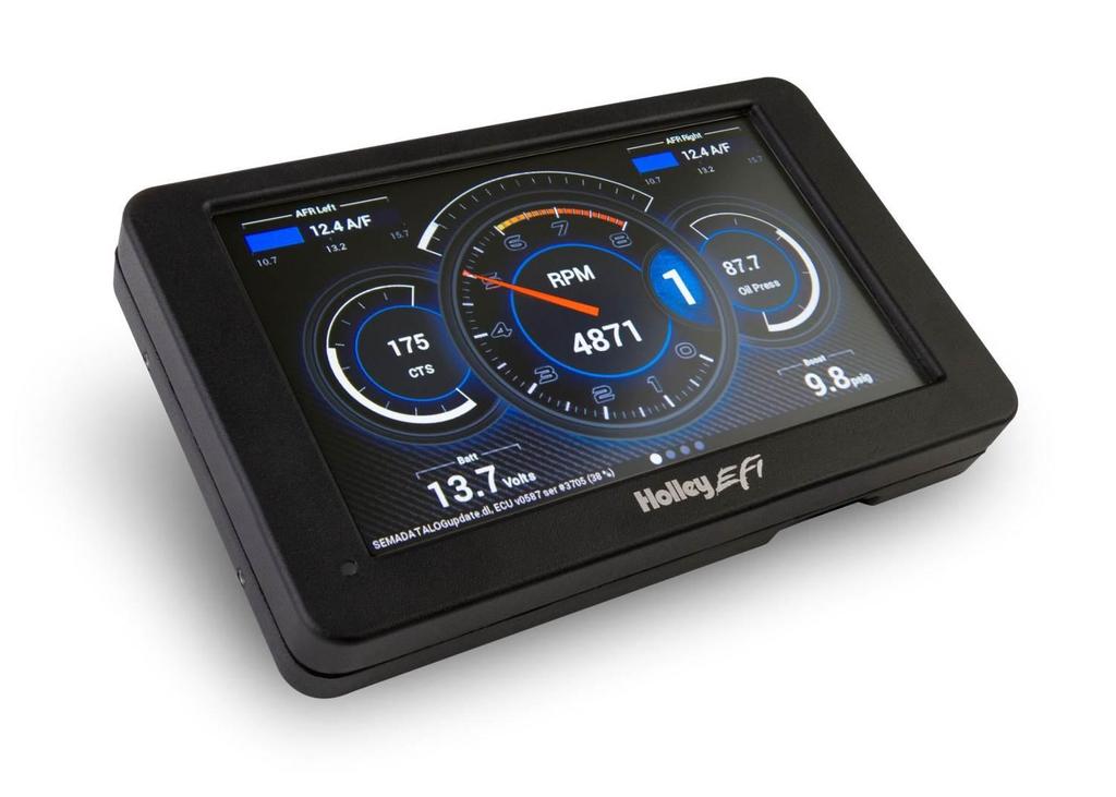
4 Introduction The Holley EFI Digital Dash is completely customizable with a variety of gauge and indicator screens that can be programmed to display any parameter you need. Users can select from pre-configured layouts, or personalize their own. The dash also offers a virtual switch panel, user defined alarms, configurable shift lights and can control on-screen playback of your EFI data logs. This all new Holley EFI Digital Dash claimed the SEMA New Product Award for Best Engineered New Product The Holley EFI Digital Dash measures 7.5" wide, 4.625" tall and 1" deep, making it a compact, customizable dash for use in a variety of motorsports applications. The Dash features a 7" low glare, high brightness, high contrast, full color touch screen for easy viewing even in full sun, plug and play connection to all Holley EFI systems as well as a weather proof aluminum housing featuring flexible mounting options. Monitor the power of your Holley EFI system at a glance! 4

5 Quick Start Guide A CAN/power harness is supplied with the digital dash. Connect the black wire to negative, white wire to a switched +12V circuit. Connect the harness from the CAN connector on the vehicles main harness to the digital dash using the supplied 4 CAN/Power extension Once all connections have been made the Holley EFI Digital Dash may be powered up. After a brief initial loading sequence the gauge display will appear. Package Contents Specifications General Weather-proof aluminum housing engineered to withstand harsh racing environments 7 Low Glare, High Brightness, High Contrast, Full Color Touchscreen 800x480 Resolution Operating voltage 8V - 20V Auto Brightness Plug and Play connection with all Holley EFI systems via CAN bus Completely customizable display of all EFI parameters including every user configured input and output Multiple gauge and indicator types with limitless customization options Quickly toggle between two or more active screens (tune, warm-up, race, drive, etc.) Virtual switch panel User defined channel alarms Configurable progressive shift lights and light bar On screen playback of EFI data logs Download and save Holley EFI data logs to external USB memory stick Expandable internal storage on micro SD card Flexible mounting options Support for future USB devices Upgradable with future software/firmware enhancements Multiple units can be used simultaneously on a Holley EFI system for larger dashboards Internal 3-axis accelerometer 5

6 Mounting The product has eight tapped 8-32 mounting holes to allow the user to surface mount or flush mount the enclosure. There are four mounting holes located on the rear of the unit, and two mounting holes are located on the left and right sides. Included with the contents of this kit is a separate template with a 1:1 layout of the hole locations for fabricating a mounting bracket. NOT TO SCALE USE THE TEMPLATE INCLUDED IN YOUR KIT 6


7 Connectors CAN1/Power 4 pin Mizu-P25 male receptacle connector used to connect main power and to a Holley EFI. The dual connector allows the product to be connected to multiple devices on the CAN bus. USB Pin Function Color Description 1 +12V WHT Main power in 2 CAN1H ORG/BLK CAN_H Holley EFI communications 3 CAN1L ORG CAN_L Holley EFI communications 4 GND BLK GND The unit has two standard USB type A receptacles that can accept USB flash drives for saving data logs, uploading gauge screen layouts, background images, or firmware updates. CAN Adapter Harness 271R1075A CAN ADAPTER HARNESS - used to connect switched +12V ignition power (white wire) and ground (black wire) to the dash, as well as for connecting to the main harness CAN connector. 7


8 Using the Dash Touchscreen Basics The Holley EFI Digital Dash has been designed with a resistive touchscreen, meaning it will work with bare skin, a stylus, or even through driving gloves. This dash responds to localized point pressure on the screen, not swiping, which is common on capacitive screens found on current smart phones and tablets. Dashboard The dashboard will appear when you power on your Dash. There are several screen layouts that can be selected. Press anywhere on the display to bring up the navigational buttons, then choose Next or Prev to cycle through the screen layouts. Main Menu Pressing anywhere on a gauge screen will bring up the navigational buttons. To access the main menu choose Menu in the upper right corner of the screen. Configuration The configuration screen allows you to change the display brightness, modify the number of gauge display layouts (screens), update firmware, and calibrate the touchscreen if required. 8
9 Standalone vs EFI Connected Mode The Dash has two main modes of operation, standalone and EFI-connected. If you have a Holley EFI installed in your vehicle, ensure that the standalone mode is unchecked in the configuration menu. If you are using the Digital Dash without a Holley EFI, select Standalone mode. The EFI specific Datalog and Tuning buttons will no longer be shown in this mode. Layouts You may choose the number of layouts or gauge display screens that are configured. An example would be 4 screens, representing tuning, warm up, race, and street. The Dash will use the last saved layout as the preferred screen to display at power on. Auto Brightness The Dash has an ambient light sensor at the lower left corner of the display. This sensor is used to set the backlight brightness when auto brightness is enabled. If this sensor is covered, the auto brightness feature will not function. Press on the Auto beside brightness to enable the auto-brightness function. For manual brightness control, use the slider to adjust the screen brightness. Clock The Dash has an internal real-time clock that can be adjusted using this screen. If you connect the Hz USB GPS to the Dash, please ensure the time zone is set correctly as the Dash will automatically set the clock using the GPS time. About This screen contains firmware and software version information along with the CAN id for the Digital Dash. When connected with a Holley EFI it will show details of the connected EFI. Update Firmware New or additional features developed by Holley can be added to the Digital Dash by updating firmware. These updated firmware files can be obtained by contacting tech service ( or ) or they may be downloaded from our website ( under the Fuel Injection tab. To perform a firmware update, follow these steps: 1. Extract the contents of the firmware.zip file onto a USB memory stick 2. Connect the USB memory stick to one of the USB cables on the Digital Dash. a. If the unit is off, the firmware update will take place automatically as soon as the Dash is powered on with the USB stick plugged in. No further action is required. b. If the dash is already powered on, proceed to step 3 3. Select Update Firmware from the Configuration menu and follow the on screen prompts. 9


10 Dash Configuration This option configures the local dash settings. Local I/O Tab Configures the inputs and outputs that are available using the , or I/O Adapter. Consult the I/O Adapter Instruction manual for more information on configuring the Local I/O tab. Pin refers the physical pin number on the I/O Adapter. CAN Devices Tab Configures CAN-connected devices such as the Holley LED Light Bar. 10
 or with the optional GPS (554-140).")

11 Vehicle Tab Contains settings that control the input channel that drives the internal odometer and local RPM and speed calculations. The odometer can source can be selected from EFI Transmission Speed, an EFI input, local Dash speed input using the optional I/O adapter ( ) or with the optional GPS ( ). Trans Speed: Use with supported transmission. Requires that you have a properly setup transmission ICF in your Dominator ECU. GPS Speed: Use this setting with the Holley GPS module. No additional setup is required. Dash Speed: Use this setting when you want the speedometer and odometer to read from a speed sensor going directly to the dash on IO3 or IO4 of the optional I/O adapter harness This is the only setting that requires you to fill out the Local Dash Speed Calculation area on the Holley Digital Dash. ECU Input: Use with a custom speed sensor input from the I/O section of your Holley ECU. The ECU input must be named speed and the units set to miles/hour for the odometer to report distance accurately. 11


12 Misc Tab The touch screen is calibrated at the factory and should not require any adjustments. If the touch screen drifts due to environmental factors it can be re-calibrated from this menu. Dashboard This selection returns you to the operational dash layout. Data Log The Holley EFI Digital Dash allows you to retrieve, delete and configure data logging with the attached HEFI. Data logs can be saved internally or to a USB memory stick for viewing on a computer. Utilities The utilities menu is described later on in the manual. Customize Select this button to enter gauge customization mode. These functions are covered later on in the manual. Customizing Your Layout Choosing Customize from the Main Menu enables the gauge customization mode. Entering this mode will allow any of the preconfigured layouts to be modified, or one may be built from scratch. Gauges can have independent warnings and ranges set, even if they are connected to the same monitored value. Import/Export The import function will load any saved gauge layout (.ini file) to the active screen. The export function will allow any gauge layout to be saved internally or to a USB Memory Stick. Preconfigured layout examples and filenames are outlined later in this manual. Starting from a Blank Layout To begin building a custom layout from a blank template, touch any bare area of the background. Choose Layout > Import > Clear 12


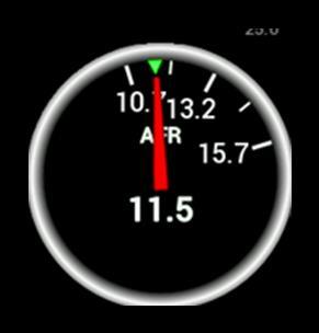
13 Adding Gauges Press on the display where you want a gauge to appear, then click Add > Gauge > Value to Monitor > Gauge Type. Once you have selected the gauge type you will be asked to select the value to monitor. Every available EFI channel including user configured inputs and outputs will be shown in this list (see Appendix A). Once the value is chosen the gauge will be placed on the screen. 1. Select Add 2. Select Gauge 3. Select Value to Monitor 4. Select Gauge type Step 1 Step 2 Step 3 Step 4 Gauge Types See page 14 for pictures of all gauge types. Analog Traditional style gauge with a sweeping needle Bargraph Bargraph gauges can be oriented horizontally or vertically. Digital Meter Numeric value readout Thin Analog Round gauge with a sweeping bar instead of a needle. AFR Meter The AFR meter is more of a lean/rich indicator. There is a green target that shows the current Target AFR that is programmed in the map. In closed loop, the gauge face will rotate so that the target AFR is pointing north on the gauge. The needle and digital value shows the current AFR reading. In this fashion, if the needle is pointing to the left the engine is running rich, and if the needle points to the right the engine is running lean. The AFR meter option will only appear on AFR channels. 13
14 Symbol The symbol gauge type will change its color based on settings in the warnings section for this gauge. This can be used to display an automotive symbol warning light or normally hidden text that will be displayed when an alarm condition is reached. Status LED The status LED illuminates when the monitored value reaches the programmable caution high or low values. Graph The graph type show a plot of a monitored value. RPM Bar The RPM bar consists of 10 LEDs, comprising three programmable ranges. The Green LEDs illuminate from the minimum range value to normal high value. The Red LEDs illuminate in the Normal High through Caution High values. The 5 Blue LEDs illuminate once Caution High is exceeded. A standard configuration for a 7000 RPM shift would be to set: Minimum range to 4000 Normal high to 6500 Caution high to 7000 rpm The color of each zone can be chosen by the user. RTC Channel RTC is a clock and can be configured as an analog or digital gauge. 14


15 Gauge Type Examples: ANALOG BARGRAPH DIGITAL METER STATUS LEDS RTC AFR METER THIN ANALOG GRAPH RPM BAR 15

 from the")


16 Customizing the Gauge While in Customize mode, touch the gauge you would like to modify and a menu will appear. To move the gauge select Move (A) and drag the gauge to place it in the desired location. To customize the visual properties and warning indicators, select Customize (B) from the pop up menu. In the scroll window you can see the parameters that are configurable. A B Label The Label is used to name the gauge. Use the Visible check box to enable or disable it. To edit the label, select the text box and a full keyboard will appear. To use a symbol instead of text, touch the Sym button. There are two Symbol keyboards, pressing the shift key will toggle between the two. When finished, press Ok. 16


17 Font Size This is used to adjust the font size of labels within the gauge. Touch inside the text box to bring up a number keypad. The top of the keypad will display the minimum and maximum text size values (in pixels). In this case, the minimum is 5 and maximum is 240. Units The Units label can be modified in the same fashion as the gauge label. To do this, touch inside the text box to bring up the keyboard. When finished, press Ok. 17


18 Range This will adjust the minimum and maximum display range of the gauge. Warnings for Gauges Configuring warnings will dictate when the gauge changes colors. When values reach the Low Warning or High Warning value, the gauge face will change to the color beneath that value. When the gauge value reaches Low Alarm or High Alarm, the gauge face will change to the corresponding color. You can click on the color bar beneath the values to change the corresponding color. Warnings for LED Status Lights or Symbols In the case of LED Status Lights, the color of the LED is chosen by clicking on the color bar beneath the warning values. The corresponding enable must also be set. Figure A shows an example of a CTS setup, where the LED would change from blue, violet, green, yellow and red throughout its range of values. 18
 Figure A. CTS Warning Example A status LED can be lit to show when an item is either on or off.")
19 Symbols are similar, which will change color based on its corresponding value channel. In this manner you can duplicate the function of lit symbols on your dashboard. Status LEDs for Switched Items (ON/OFF) Figure A. CTS Warning Example A status LED can be lit to show when an item is either on or off. To have an LED lit for when an item is turned on, configure per Figure B. To have an LED lit for when an item is turned off, configure per Figure C. The LED will be grey when in the normal state. Figure B. Blue LED when output is ON Figure C. Red LED when output is OFF 19


20 Full color configuration and Alpha control (transparency) can be used with Status LEDs. Touch the rectangular color bar below the value input box to change colors. Status LED Configuration Status LED Color Configuration Alpha Channel example from left to right (75, 150, 255) 20


21 Peak Hold Enabling the Peak Hold features will place a marker at the highest and/or lowest value for quick viewing. This feature is similar to the traditional Tattletale Tachometers. The minimum peak is shown with a blue triangle, and the maximum peak is a red triangle. Gauge Sweep Users can configure the sweep angle of Analog and Thin Analog gauges. These values are in degrees. Positive values are in a clockwise direction and negative values are in a counter-clockwise direction. There are three buttons that will set the sweep to a standard 270 degree, 120 degree, or 90 degree gauge. View examples below o clock 0 12 o clock 30 1 o clock o clock 60 2 o clock o clock 90 3 o clock o clock o clock o clock o clock o clock 21

22 Gauge Sweep Examples: -120 Start / 120 End 120 Start / -120 End Foreground Color -205 Start / 45 End 0 Start / 90 End Changing the foreground color will modify the text, labels and values of a gauge. Use a stylus to drag the crosshair to the desired color. The rectangular box at the bottom of the screen will show a preview of what is being selected. Custom colors can be saved for future use by using the stylus to drag from the rectangular preview box and drop onto one of the custom color boxes at the bottom left of the screen. Choose Ok when finished. 22


23 Background Color Changing the Background Color of a gauge is done following the same steps as the Foreground Color. The alpha channel controls the transparency of the background. Transparency The transparency of a gauge background can be modified to achieve your desired style. A value of 255 makes the gauge completely opaque, and a value of 0 makes the gauge completely transparent. This is the same as setting the alpha channel in the color selection box for the gauge background. See the examples below. Transparency values are 255 / 125 / 0 Transparency values are 255 / 150 / 65 / 0 23
24 Precision Changing the precision of a gauge will show more or less decimal points after the whole number. Tachometers generally will not use any decimal places; however it may be beneficial to display fuel flow or AFR values with one or more decimal place. Segments Users can configure the number of segments on gauges. For example, a RPM tachometer with 8 segments would be divided into 1000 RPM increments. A 0-16,000 RPM tachometer would be divided into 2000 RPM increments. Choose 0 segments to remove the scale completely. NOTE: Ensure the number of segments is matched up with the range you specify. E.g. If you choose 6 segments in a tachometer range, the scale markers will be at 0, 1333, 2667, 4000, 5333, 6667, and We would recommend using 4 or 8 segments instead. Scale Values Visible This will toggle the Scale Values on or off. Scale Divisor This value is the total range of a gauge divided by the number of segments. In this example, if you wanted the Scale Values of the tachometer to display 10, 20, 30 instead of 1, 2, 3 the scale divisor would be set to 100 instead of


25 Size Overall Gauge sizes can be adjusted by increasing or decreasing their pixel size. The minimum and maximum values are displayed near the top of the number keypad. In this case, the min is 20 and the max is 780. Value Display When Value Display is enabled, a digital meter will appear inside an analog gauge showing real time values in addition to the needle indicator. Updates per Second This changes the speed at which values are refreshed on the dash and can be changed from 1/sec to 10/sec or full rate. These should be adjusted upon user preference. Border Borders around certain gauge types can be enabled or disabled by toggling this selection. 25
 box. (Example, enter 1.60934 to convert MPH to KM/H). Conversion a b c PSI to kpa 0 6.895 0 kpa to PSI 0 0.145 0 MPH to km/h 0 1.")


26 Channel Math Channel Math can be used to perform unit conversion on any gauge. The default value is 1 and this should be used if no conversion is desired. Any unused value may remain zero. For simple multipliers use the Multiplier (b) box. (Example, enter to convert MPH to KM/H). Conversion a b c PSI to kpa kpa to PSI MPH to km/h Temperature gauges can from F to C by using the F to C radio button. Selecting this option will automatically update the unit s label of the gauge and disable the user-defined multiplier. If any gauges appear to read incorrectly, be sure to verify that this multiplier value has not been inadvertently changed. Adding Labels Labels can be added anywhere on the gauge screen. The customization options for Labels include Font Size, Foreground & Background colors, and Transparency. See below for an example of the variety of sizes, colors and symbols that can be used. Adding Switches Switches can be placed anywhere on the gauge screen, they can be used to turn devices on or off, as a nitrous enable, etc. These functions are mapped through the Holley EFI software. Follow these steps for proper configuration: 26


27 1. Create an input in the I/O screen and give it a name for this example we have named it SWITCH 1 2. Create an output in the I/O screen and give it a name in this example we have named them Cooling Fan, Elec Water Pump, and NOS Bottle Htr. Once named, choose Configure at the right of the screen. 3. Set the Switched Input Trigger to activate when SWITCH 1 is enabled 4. Go to the PIN Map Icon, select View LCD and drag the switch inputs to the appropriate pin number. 27


28 5. Select View Outputs from the Pin Map and drag the outputs to the whatever pin location the device was wired to. 6. You will have to send the new configuration to the EFI and toggle the ignition for approximately 5 seconds for the changes to be saved. Turn on the ignition to continue. 7. Place a switch on the Holley EFI Digital Dash gauge screen by choosing Add then Switch. An option box in the upper right hand corner of the switch customize menu will allow mapping of the switch to the proper LCD Pin Map number that was configured in the Holley EFI software. 8. Customize the switch Label and other properties on the Dash and choose Ok. Changing the Background The Holley EFI Digital Dash comes preloaded with a variety of background images and gauge templates (see Appendix C). Users can also upload their own background image from a USB memory stick. Background images should be 800x480 resolution, in.jpg or.png file format. To change the background, enter the customize menu and choose Background. A file directory will open listing all available background images. To choose one from a USB drive, select USB on the left side of the screen and that drive s files will then be shown. Choose a background filename, and press OK to replace the current background. The background image is copied to the internal memory of the Dash so the USB does not have to be present for that background to be used. 28

.")

29 To remove the background from the current layout, press Ok without selecting a filename. Saving Your Layout Once a layout has been created it must be saved. Touch any blank portion of the gauge screen and select Save. Exporting / Importing Layouts You can save a copy of your layout in Customize mode by touching on any blank portion of the gauge screen and select Layout > Export. At this point, the layout can be given a name and saved internally to the Dash or to an external USB drive (if present). Click on the filename field to bring up a keyboard to personalize the filename. Once you have successfully saved the layout, touch any blank portion of the gauge screen and choose Save or you may choose Save from the top right hand corner of the gauge screen to return to the dashboard screen. Importing Layouts You may import a layout from the defaults directory or USB drive by selecting Layout->Import. Navigate to the screen you want to import and select Import. Touch any blank portion of the gauge screen and choose Save to return to the dashboard screen. 29


30 Start-up Gauge Layout The Dash will use the last saved layout as the start-up layout. To configure the screen that will be shown upon start-up of the Dash, follow these steps: 1. Toggle to the screen you would like displayed each time the unit is powered on. 2. Enter Customize from the Main Menu. 3. Choose Save in the top right corner of the gauge screen. Preconfigured Layouts The Holley EFI Digital Dash comes standard with ten preconfigured gauge layouts. The first four of these layouts are active by default. If a smaller or larger number of layouts are desired, select Configuration from the Main Menu. The minimum number of layouts is two and the maximum is ten. Below are examples of the ten preconfigured layouts: Layout 1 Layout 2 Layout 3 Layout 4 30


31 Layout 5 Layout 6 Layout 7 Layout 8 Layout 9 Layout 10 31

32 Modifying Channels on a Preconfigured Layout Any gauge channel can be changed to meet user needs. To do this, touch the gauge to modify and press Customize. At the top right corner of the customize gauge menu is a button that will allow the user to redefine the channel being displayed. For instance, fuel pressure on Layout 10 could be changed to display Boost. NOTE: Only the gauge value being display will be updated, the user MUST manually change Labels, Units, Range, Warnings etc. with proper values as these will NOT be updated automatically! Refer to the Customizing Your Layout Section of this manual for instructions on gauge customization. Data Log Record and Playback Local Data Record The Holley EFI Digital Dash has a record button that will record data logs directly to a USB flash drive or internal storage. The record button can be shown by pressing anywhere on the dashboard display. Pressing this button will record accelerometer data, local dash inputs, ECU broadcast data and the data from the optional GPS directly to a USB flash drive or internal storage. The data is recorded in the standard Holley Log File format and can be examined using PC software. Data Log Playback The Holley EFI Digital Dash will play back logs that have been locally recorded using the Record button or retrieved from a Holley EFI ECU. Pressing on the Playback button in the upper left corner of the dashboard screen allows you to play back these logs from the Dash s internal storage or a USB drive. The data log playback will animate the gauges with data that has been previously recorded. To return to the live data display, a Stop button can be used from on the on-screen menu to stop the playback at any time. 32


33 USB Flash Drive Removal If a USB Flash drive is plugged into one of the USB ports on the Digital Dash, an eject button will appear in the lower right corner of the dashboard on-screen menu. This ensures that all files are closed on the USB drive allowing a safe removal. Utilities Menu From the utilities menu, you can upload/download global EFI configurations, access file utilities, backup/restore the dash configuration, and adjust security settings. Press on the X at the top left corner to return to the main menu. Global Config A global configuration contains the complete configuration of a Holley EFI in a single.hefi file. The Dash can upload and download global configs to the connect EFI. 33


34 Downloading the Current EFI Configuration Connect a USB flash drive to one of the USB cables attached to the Dash. Navigate to the desired device and folder where you want to store the current EFI configuration, and press Download to start the transfer. Uploading a New EFI Configuration To upload a new configuration to your Holley EFI, first ensure that the engine is not running. Navigate and select the desired.hefi configuration file and press Upload to ECU to start the transfer. Deleting EFI configuration files If you no longer want to have a copy of the.hefi file you may remove it. Navigate to the desired file and press Delete. File Utilities The utilities screen allows users to perform file functions such as deleting files and copying files to USB memory sticks. 34


35 Backup/Restore Backup/Restore can be used to duplicate a dash configuration on a new dash. The backup includes all local dash configuration settings and screen layouts. Backup To create a backup copy of the complete Dash configuration, choose Backup Configuration. Navigate to where you want the backup file stored, adjust the filename if necessary and press Save. Restore To restore a previously saved configuration, select the Restore Configuration from the menu, locate the desired Dash_Config_*.tgz file and press Restore. Security Settings The Dash has the ability to lock out certain functionality. To disable a particular feature, place a checkmark beside the feature you wish to lock out. Default Password Before you can change any settings, you will need to enter the default password of holley (without quotes.) 35
36 Item Internal Datalog Screen 1-4 Edit Screen Edit/Customization ECU Log ECU Tuning ECU Global Upload/Download Firmware Update File Util Backup/Restore Standalone Choice Dash Configuration Odometer Source Effect when checked (locked out) Does not allow the user to record or play back a locally recorded logfile. Does not allow the user to change the first four layout screen on the dashboard. Screens 5-10 are still editable. No screens can be edited or customized. The user cannot download log files from the ECU. The ECU Tuning menu is disabled Global.hefi files cannot be uploaded or download to/from the ECU. The firmware cannot be updated on the unit. File utilities menu is disabled Dash backup and restore functionality is disabled The user cannot switch between standalone and EFI-connected mode. The user cannot change the local dash channel configuration, can device configuration, vehicle settings, or touchscreen calibration. The odometer source cannot be changed. Once you have changed the options, click on the password box and enter a password to protect the option selections. The password is not echoed on the screen. You must confirm the password before you are allowed to save the selections. If the options are greyed out, you will need to enter the password before you can change the options. 36

37 EFI Tuning The Digital Dash has been equipped to tune most of the EFI parameters. It is expected that the user is familiar with the PC tuning software and general EFI tuning principles. From the main menu, choose the Tuning menu to adjust most of the parameters in your Holley EFI. Menu Organization The left side contains the list of menus and items that can be used to change parameters on the EFI. Menu Basic Advanced Tuning Performance System Setup User 1 User 4 Parameters Basic tuning parameters including fuel, closed loop/learning speed, spark, transmission shifts. Detailed fueling, idle, spark and individual cylinder tuning. Performance items such as Launch, Rev Limiters, Nitrous, Boost, Traction Control, Water/Methanol, and Advanced Tables. Initial EFI configuration and other system options including Fans, Fuel Pump, A/C Shutdown, Engine Setup, Diagnostics selection, Ignition, Transmission. TPS autoset and Static Timing are also available from the System Setup Menu. Four user-customizable menus Using the Tuning Menu There are a number of different editors based on the value you choose to edit. The current value is displayed in light blue beneath the parameter label. Enable/Disable Toggle Pressing on a toggle type menu item will toggle the state between disabled and enabled. Note that some additional parameters may appear in the menu list once enabled. For example, the Fan 1 on and off settings are not shown if Fan 1 is disabled. 37


38 Numeric Editor Selecting a parameter with a numeric value will bring up a numeric keypad and slider bar on the right half of the screen. You may use either the slider or keypad to change the value. The parameter limits are shown near the slider bar. Pull-Down/List Parameters that have specific choices are displayed in a pull-down list. The current setting is displayed in blue, and pressing on the parameter brings up a pull-down list on the right side. 38


39 Graph Editor Parameters that are graphical will bring up the graph editor. Graphs can be edited by selecting a point and dragging it up and down, or by clicking on the yellow value box near the point you wish to edit. Multi-series graphs have a selection on the right hand side to select the series you are editing. The series that can be edited is shown in yellow. In the example below, 3-4 Upshift is selected. 39


40 Table Editor In table editor you can select a single cell or multiple cells to edit. Press once on a single cell to select it, then press a second time to bring up the numeric table editor. Multiple cells may be edited by first pressing and dragging to highlight the desired cell range in blue. Press on any blue selected cell to bring up the numeric table editor. To perform smooth and interpolate operations, first select a range of cells then press on any selected cell to bring up the editor. Select Smooth or Interpolate then press Ok. To perform an action, select the desired function, type in a value and press Apply. Changes are not sent to the EFI until the Save button is pressed. Function Set Value Add/Subtract Offset by % Multiply Divide Smooth Selection Interpolate Selection Description Sets all selected cells to the same value Adds an offset to the selected cells. Offsets each selected cell by a percentage. 100% doubles the value. Multiples each selected cell by a value Divides each selected cell by a value Smooths the selection using neighboring cell values Perform a linear interpolation of values using the four corner cells in the selection 40

41 User Customizable Menus You can change the title of the user customizable menu by pressing on the menu label for more than 2 seconds. A keyboard will appear allowing you to change the name of the menu. To add items to a user menu, you must first navigate to the desired item. Press on the desired menu item label for more than 2 seconds and a dialog box will appear allowing you to select which menu to add or remove this item to. Cleaning If screen needs cleaning, use the supplied microfiber cleaning cloth. Do not use harsh chemical cleaners on the touch screen display. Do not subject the display to a high pressure water stream from a pressure washer. 41
42 Appendix A List of EFI Monitored Values Below is a list of 283 values that can be monitored. Any user programmed I/O values will appear in the list in addition to these once the Dash has been connected to a Holley ECU. RTC INJ PW1 N2O STAGE 6 DIAG #10 RPM INJ PW2 N2O STAGE 7 DIAG #11 INJ PW INJ PW3 N2O STAGE 8 DIAG #12 DUTY CYCLE INJ PW4 GPO 1 DIAG #13 CL COMP INJ PW5 GPO 2 DIAG #14 TARGET AFR INJ PW6 GPO 3 DIAG #15 AFR LEFT INJ PW7 GPO 4 DIAG #16 AFR RIGHT INJ PW8 GPO 5 DIAG #17 AFR AVERAGE INJ PW9 GPO 6 DIAG #18 AIR TEMP ENR INJ PW10 GPO 7 DIAG #19 COOLANT ENR INJ PW11 GPO 8 DIAG #20 COOLANT AFR OFFSET INJ PW12 N2O ENABLED ADV LAUNCH INPUT AFTERSTART ENR CYL FUEL CORR1 N2O INPUT #1 ADV SHIFT INPUT CURRENT LEARN CYL FUEL CORR2 N2O INPUT #2 ADV GEAR CL STATUS CYL FUEL CORR3 N2O INPUT #3 ADV AT 1D1 LEARN STATUS CYL FUEL CORR4 N2O INPUT #4 ADV AT 1D2 FUEL ECONOMY CYL FUEL CORR5 N2O INPUT #5 ADV AT 1D3 FUEL FLOW CYL FUEL CORR6 N2O INPUT #6 ADV AT 1D4 MAP RoC CYL FUEL CORR7 N2O INPUT #7 ADV AT 1D5 TPS RoC CYL FUEL CORR8 N2O INPUT #8 ADV AT 1D6 TUNING CHANGE CYL FUEL CORR9 N2O PURGE ADV AT 1D7 ESTIMATED VE CYL FUEL CORR10 N2O LEAN CUTOFF ADV AT 1D8 IGNITION TIMING CYL FUEL CORR11 N2O RICH CUTOFF ADV AT 2D1 KNOCK RETARD CYL FUEL CORR12 N2O RPM CUTOFF ADV AT 2D2 KNOCK LEVEL CYL FUEL CORR13 N2O MAP CUTOFF ADV AT 2D3 IAC POSITION CYL FUEL CORR14 N2O PURGE OUTPUT ADV AT 2D4 MAP CYL FUEL CORR15 N2O DRY FUEL 1 ADV AT 2D5 TPS CYL FUEL CORR16 N2O DRY FUEL 2 ADV AT 2D6 MAT CYL TIMING CORR1 N2O DRY FUEL 3 ADV AT 2D7 CTS CYL TIMING CORR2 N2O DRY FUEL 4 ADV AT 2D8 BARO CYL TIMING CORR3 N2O DRY FUEL 5 ADV AT 1D/GEAR 1 BATTERY CYL TIMING CORR4 N2O DRY FUEL 6 ADV AT 1D/GEAR 2 OIL PRESSURE CYL TIMING CORR5 N2O DRY FUEL 7 ADV AT 1D/GEAR 3 FUEL PRESSURE CYL TIMING CORR6 N2O DRY FUEL 8 ADV AT 1D/GEAR 4 PEDAL POSITION CYL TIMING CORR7 N2O TIMING MOD1 ADV AT 1D/GEAR 5 MAIN REV LIMIT CYL TIMING CORR8 N2O TIMING MOD2 ADV AT 1D/GEAR 6 REV LIMIT #1 CYL TIMING CORR9 N2O TIMING MOD3 ADV AT 1D/GEAR 7 REV LIMIT #2 CYL TIMING CORR10 N2O TIMING MOD4 ADV AT 1D/GEAR 8 AC KICK CYL TIMING CORR11 N2O TIMING MOD5 ADV AT 2D/GEAR 1 TIMING RETARD #1 CYL TIMING CORR12 N2O TIMING MOD6 ADV AT 2D/GEAR 2 42
43 TIMING RETARD #2 CYL TIMING CORR13 N2O TIMING MOD7 ADV AT 2D/GEAR 3 TIMING RETARD #3 CYL TIMING CORR14 N2O MTIMING MOD8 ADV AT 2D/GEAR 4 FAN #1 CYL TIMING CORR15 N2O TIMER1 ADV AT 2D/GEAR 5 FAN #2 CYL TIMING CORR16 N2O TIMER2 ADV AT 2D/GEAR 6 #2 FUEL PUMP TGT FUEL PRESSURE N2O TIMER3 ADV AT 2D/GEAR 7 AC SHUTDOWN BOOST PSIG N2O TIMER4 ADV AT 2D/GEAR 8 TCC LOCKUP BOOST GEAR N2O TIMER5 ACC X SENSOR WARNING BOOST STAGE N2O TIMER6 ACC Y SENSOR CAUTION BOOST N2O TIMER7 ACC Z BASE FUEL LB BOOST SPEED N2O TIMER8 GPS QUAL BASE FUEL VE BOOST TIME TRANS GEAR GPS SPEED BASE TIMING TARGET BOOST TRANS SPEED GPS LAT BASE TAFR TRANS BRAKE LINE PRESSURE GPS LONG BASE IGN DWELL BOOST SCRAMBLE + INPUT SHAFT SPEED GPS ELV VOL COMP IGN DWELL BOOST SCRAMBLE - ACCUM PRESSURE GPS DIR INJ END ANGLE MANUAL BOOST BUILD TCC DUTY CYCLE DASH IO1 ECU LOG TRIGGER MANUAL BOOST RESET LINE TEMP DASH IO2 TIMING AIR TEMP BOOST BUILD TORQUE TIME DASH IO3 TIMING COOLANT TEMP BOOST SOLENOID DUTY TRANS MAN UPSHIFT DASH IO4 STATUS1 BOOST SAFETY TRANS MAN DNSHIFT DASH IO5 STATUS2 BOOST MASTER ENABLE TRANS AUTO/MAN DASH IO6 STATUS3 BOOST MANUAL SHIFT IN TB TPS #1 DASH IO7 STATUS4 BOOST MANUAL STAGE IN TB TPS #2 DASH IO8 STATUS5 BOOST FILL SOL DC PEDAL TPS #1 DASH IO9 STATUS6 BOOST VENT SOL DC PEDAL TPS #2 DASH IO10 STATUS7 W/M INJECTION TB2 TPS #1 DASH CAN1 STATUS8 W/M MANUAL ENABLE TB2 TPS #2 DASH CAN2 INJ PPH1 W/M LOW FLUID TB POSITION DASH CAN3 INJ PPH2 W/M PUMP STATUS TB2 POSITION DASH CAN4 INJ PPH3 W/M SOL FLOW1 BRAKE PEDAL DASH CAN5 INJ PPH4 W/M SOL FLOW2 DIAG #1 DASH CAN6 INJ PPH5 W/M TOTAL FLOW DIAG #2 DASH CAN7 INJ PPH6 W/M SOL DC1 DIAG #3 DASH CAN8 INJ PPH7 W/M SOL DC2 DIAG #4 DASH CAN9 INJ PPH8 N2O STAGE 1 DIAG #5 DASH CAN10 INJ PPH9 N2O STAGE 2 DIAG #6 DASH ODOMETER INJ PPH10 N2O STAGE 3 DIAG #7 INJ PPH11 N2O STAGE 4 DIAG #8 INJ PPH12 N2O STAGE 5 DIAG #9 43


44 Appendix B Increasing Internal Logging Storage (micro-sd card) To increase the storage space for internal logging, you may purchase a micro-sd card and install it inside the unit. Please turn off power to the unit before opening the access panel. Using a Philips screwdriver, carefully remove the rear access panel. Remember to ensure the rubber strip is replaced before closing the unit, to keep liquid out of the unit. Figure 1. Slide door to the left to unlock Figure 2. Flip up door Figure 3. Insert micro-sd card 44

 Y Resistive Sensor to GND Y Y Y CTS / MAT Sensor to GND Y Y Y Fuel sender input Y I/O Connector Supported Functions Pin Function Sample use 1 5V EXC 5V excitation output for sensors 2")
45 Figure 4. Flip door down Figure 5. Slide door to the right to lock Optional I/O Connector The internal I/O connector can be used for stand-alone applications or as additional inputs and outputs. An optional I/O adapter is available as part number , or IO1 IO2 IO3 IO4 IO5 IO6 IO7 IO8 IO9 IO10 SSR GND switched output (2A) Y Y 5V Input Y Y Y Y Y Switch to GND input Y Y Y Y Y Y Y Switch to +12V input Y Y Y Y Y Y Y RPM Input Y Y Speed Input Y Y Oil Pressure (5V) Y Resistive Sensor to GND Y Y Y CTS / MAT Sensor to GND Y Y Y Fuel sender input Y I/O Connector Supported Functions Pin Function Sample use 1 5V EXC 5V excitation output for sensors 2 IO1 Left turn input or General I/O 3 IO2 Right turn input or General I/O 4 IO3 Digital Engine RPM input or General I/O 5 IO4 Digital Speed Input or General I/O 6 IO5 High beam input 7 IO6 Brake input 8 IO7 Oil pressure input 9 IO8 Oil temperature sender input, built-in pullup 10 IO9 Coolant temperature sender input, built-in pullup 11 IO10 Fuel sender input, built-in pullup 12 GND Ground reference I/O Connector Pinout 45


46 Appendix C The following preloaded background images can be found in /internal/images. LAYOUT1 LAYOUT2 LAYOUT3 LAYOUT4 LAYOUT5 LAYOUT6 46


47 LAYOUT7 LAYOUT8 LAYOUT9 LAYOUT10 Holley_EFI_1 Holley_EFI_2 BlackStone Fire2 3_gauge_dark_lt_blue 47 3_gauge_dark_orange
48 3_gauge_dark_pink 3_gauge_dark_purple 3_gauge_dark_red 3_gauge_dark_teal 3_gauge_dark_yellow 3_gauge_dark_green 3_gauge_blue 3_gauge_red 48
49 3_gauge_lt_blue 3_gauge_lt_green 3_gauge_green 3_gauge_orange 3_gauge_pink 3_gauge_purple 3_gauge_teal 3_gauge_yellow 49


50 2_gauge_black 3_gauge_black 1999R10746 Revision Date:
Holley EFI Digital Dash. User Manual
 Holley EFI Digital Dash User Manual CONTENTS Introduction... 4 Quick Start Guide... 5 Package Contents... 5 Specifications... 5 General... 5 Mounting... 6 Connectors... 7 CAN1/Power... 7 USB... 7 CAN Adapter
12.3 Pro Dash Quick Start Guide
 12.3 Pro Dash Quick Start Guide 553-111 CONTENTS: Package Contents... 3 Mounting... 3 Connections... 4 Main Connector... 4 CAN Extension Harness... 6 USB... 7 GPS Antenna... 7 Cleaning... 7 Touchscreen
Digital Dash I/O Adapter Configuration
 Digital Dash I/O Adapter Configuration The I/O Adapter adds ten inputs/outputs to the 7 digital dash. These inputs and outputs can then be configured as gauges or switches, and data logged locally through
Options. Parts List. Optional Expansion Hub Optional Ignition Module Optional Memory Card
 Options Optional Expansion Hub Optional Ignition Module Optional Memory Card View boost, speed, and gear on the LCD Display. View the ignition changes on the LCD Display. Log and store map data. Card storage
Table of Contents. Part I USB Communication. Part II User Interface. Part III User Settings (Tab Control) DFS-1000 Dataview. 2 File Menu.
 DFS-1000 Dataview. 2 File Menu.") 2 Table of Contents Part I USB Communication 3 1 Important... Information 3 2 Connecting... Controller 3 Part II User Interface 4 1 Overview... 4 2 File Menu... 5 3 Options... Menu 6 4 Help Menu... 6 5
2 Table of Contents Part I USB Communication 3 1 Important... Information 3 2 Connecting... Controller 3 Part II User Interface 4 1 Overview... 4 2 File Menu... 5 3 Options... Menu 6 4 Help Menu... 6 5
Installing the EFILive DSP² Custom Operating System & Using the DSP² features of EFILive V7
 Installing the EFILive DSP² Custom Operating System & Using the DSP² features of EFILive V7 Ross Myers Installing an EFILive DSP² Custom Operating System & Using the DSP² features of EFILive V7 Copyright
V5 Build 100 SOFTWARE AND FIRMWARE UPDATES
 V5 Build 100 SOFTWARE AND FIRMWARE UPDATES Who should update: It is recommended that any user update to this latest version of software and firmware. There are improvements to laptop communication speeds
700TSU INSTALLATION MANUAL
 M 700TSU INSTALLATION MANUAL 2 Table of Contents Features...03 Specifications...04 Quick-Start...05 Remote Control...07 Hardware Installation...10 Software Installation...14 Touch Screen Driver Installation
Version 2.031, Firmware doesn't contain all listed features and fixes is the proper one
 Version 2.035, 29-03-2017 Bug from versions 2.030 2.034 with pullups when BT CAN stream enabled fixed, Gear detection bug fixed 1JZ/2JZ CAM#2 support added for faster synchronization For ALS pedal position
Haltech IQ3 Street Dash Guide
 Haltech IQ3 Street Dash Guide Thank you for purchasing a Haltech IQ3 Street dash. This guide provides information on the installation and basic use of your dash. Your dash is preconfigured by Haltech with
Features: Contents: If you are missing any of the above components please contact Racepak at
 -------------------------------------------------------------------------------------------- 250-DS-UDX -------------------------------------------------------------------------------------------- Features:
User Guide. Model: ELT0702
 User Guide Model: ELT0702 Welcome! Thank you for purchasing your new Epik Learning Tab Jr. This User Guide will provide step-by-step instructions to help you learn to use your new device. After opening
Instruction and Operations Manual
 1 GARTECH Enterprises, Inc. Rev 2 01-23-09 Instruction and Operations Manual Portable Test Cell Overview The primary purpose of the Portable Test Cell is to allow the user the ability to control the engine
MULTI-FUNCTION DISPLAYS A3416: 8 INCH / A3417: 13.3 INCH
 Multi-Function Displays (A3416 & A3417) - Overview, Configuration MULTI-FUNCTION DISPLAYS A3416: 8 INCH / A3417: 13.3 INCH The OctoPlex A3416/A3417, Multi-Function Displays allow for the users to control
MTX-D Ethanol Content and Fuel Temperature Gauge User Manual
 MTX-D Ethanol Content and Fuel Temperature Gauge User Manual P/N 3912 kit does not include flex fuel sensor. The ECF-1 is compatible with GM P/Ns 13577429 and 13577379 1. Installation... 2 1.1 Gauge Mounting...
DataPro Designer Quick Start Guide
 DataPro Designer Quick Start Guide Introduction The DataPro Designer application provides the user with the ability to configure the ULTRA-LITE PRO range of Auto Meter data acquisition products. Using
1020 / 1022 INSTALLATION MANUAL
 1020 / 1022 INSTALLATION MANUAL 2 Table of Contents Features...03 Specifications...04 Quick - Start...05 Remote Control...07 Hardware Installation...10 1020TSV, 1022TSV, 1020YV, 1022YV, 1020TSH, 1022TSH
IPM650 Intelligent Panel-Mount Display
 Quick Start Guide IPM650 Intelligent Panel-Mount Display Sensor Solutions Source Load Torque Pressure Multi Component Calibration Instruments Software www.futek.com Getting Help TECHNICAL SUPPORT For more
705 INSTALLATION MANUAL
 705 INSTALLATION MANUAL 2 Table of Contents Features...03 Specifications...04 Quick - Start...05 Remote Control...07 Hardware Installation...10 705 Models Additional Info...14 Owner s Record...15 3 Features
IS35 Color Display. User Manual ENGLISH. simrad-yachting.com
 IS35 Color Display User Manual ENGLISH simrad-yachting.com Preface Navico is continuously improving this product, therefore we retain the right to make changes to the product at any time which may not
User Guide Models: ELT0801H and ELT0703H
 User Guide Models: ELT0801H and ELT0703H Designed by the EPIK Learning Company California, USA Welcome! Thank you for purchasing your new HIGHQ Learning Tab. This User Guide will provide step-by-step instructions
Professional EFI Systems Product Catalog
 Professional EFI Systems Product Catalog Table of Contents: Section 1: ECU Options 2-8 Section 2: Various Sensors and Switches 9-14 Section 3: Display Options 15 Section 4: CAN Communication Cable 16 Section
Installing the EFILive DSP2 & DSP5 Custom Operating Systems Revision 2
 Installing the EFILive DSP2 & DSP5 Custom Operating Systems Revision 2 Installing the EFILive DSP2 & DSP5 Custom Operating Systems Copyright 1998-2008 EFILive Limited. All rights reserved First published
Smith Meter ETR-1000 Electronic Register
 MANUAL Smith Meter ETR-1000 Electronic Register Operator Reference Manual Bulletin MNTA001 Issue/Rev 0.1 (9/17) Technical Support Contact Information: Field Service Response Center 24/7 Technical Support/Schedule
PowerView Model PV750. Installation and Operations Manual Section 78
 PowerView Model PV750 Installation and Operations Manual 00-02-0686 08-20-10 Section 78 In order to consistently bring you the highest quality, full featured products, we reserve the right to change our
CH1. Figure 1: M3 LOG Advanced
 TECHNICAL DOCUMENTATION 03/09/2003 GAUGE Notes: M3 LOG Advanced technical documentation, dimensions and pinout. Ver 1.05 M3 LOG Advanced Internal lateral accelerometer CH1 Beacon Speed COM Power CH2 CH3
2013 CES (Consumer Electronics Show) C/net Best of Show.
 C/net Best of Show.") Presented by Paul Pearson National Corvette Museum, August 30, 2013 2013 CES (Consumer Electronics Show) C/net Best of Show. 2013 CTIA (Cellular Telecommunications Industry Association)2013 Emerging Technology
Presented by Paul Pearson National Corvette Museum, August 30, 2013 2013 CES (Consumer Electronics Show) C/net Best of Show. 2013 CTIA (Cellular Telecommunications Industry Association)2013 Emerging Technology
MXL PRO 05 PLUG & PLAY KIT FOR SUZUKI GSX R YOSHIMURA RACING HARNESS cc
 INSTALLATION DOCUMENTATION 18/11/2005 P&P KIT Installation Manual: MXL PRO 05 P&P kit for SUZUKI GSX R Yoshimura Racing Harness 2004 2005 1000 cc Version 1.00 Suzuki GSX-R Yoshimura Racing Harness 1000cc
VERUS Navigation Guide
 VERUS Navigation Guide diagnostics.snapon.com Contents Chapter 1: Getting Started... 3 Powering Up... 3 Module Buttons... 4 VERUS Toolbar... 5 Powering Down... 5 Emergency Shutdown... 5 Chapter 2: Scanner...
GSC400 Series. GSC400 Programmer and PC Interface User Manual
 GSC400 Series GSC400 Programmer and PC Interface User Manual GSC400 Programmer and PC Interface User Manual Full Version File: GSC400 PC Interface Rev1.2.doc, August 2009 2 of 33 Amendments Issue Section
1029 INSTALLATION MANUAL
 1029 INSTALLATION MANUAL 2 Table of Contents Features 03 Specifications 04 Quick Start..05 Remote Control.07 Capacitive Touch..10 Hardware Installation 11 1029CNH / 1029CNV / 1029TNH / 1029TNV Models Additional
VALCON EasyWriter Ver1.0E Manual
 VALCON EasyWriter Ver1.0E Manual E05172-K00022-00 Published Dec.2010 Ver3-1.03 HKS Co., Ltd. Revision History Revision Date 2008/12/10 First Edition (Ver3-1.01) 2010/4/2 Second Edition (Ver3-1.02) 2010/12/22
User Guide. Subaru Turbo (North American Models)
") User Guide Subaru Turbo (North American Models) Page 2 Table of Contents Product Introduction 4 Supported Vehicle List 4 In-Box Contents 5 What Is A Map? 7 AccessPORT Installation 8 Pre-Installation 8
User Guide Subaru Turbo (North American Models) Page 2 Table of Contents Product Introduction 4 Supported Vehicle List 4 In-Box Contents 5 What Is A Map? 7 AccessPORT Installation 8 Pre-Installation 8
M2500 Engine Controller Configuration Manual
 M2500 Engine Controller Configuration Manual Revision: 08-04-2011 Page 1 Contents 1 Preface... 4 2 Configuration from front panel... 5 2.1 Engine Controller Configuration... 6 2.1.1 RPM settings... 6 2.1.2
PowerView TM Model PV350 and PV380. Operations Manual Section 78
 PowerView TM Model PV350 and PV380 Operations Manual 00-02-0879 2012-11-30 Section 78 In order to consistently bring you the highest quality, full featured products, we reserve the right to change our
SF-901 WINDYN DATA ACQUISITION SYSTEM
 SF-901 WINDYN DATA ACQUISITION SYSTEM Update your SF-901 engine dyno with SuperFlow's advanced WinDyn 3.2 Data Acquisition System and take advantage of the latest software and data acquisition features
MEGA DIAL PANEL Instructions
 2036 Fillmore Street Davenport, Ia. 52804 563-324-1046 www.racedigitaldelay.com MEGA DIAL PANEL Instructions WARRANTY AND DISCLAIMER DIGITAL DELAY ELECTRONICS INC. WARRANTS THE PRODUCTS IT MANUFACTURES
WHIPPLE FLARE FLASH Instruction Manual
 WHIPPLE FLARE FLASH Instruction Manual 2015 AND UP Ford MUSTANG/F150 WHIPPLE SUPERCHARGERS 3292 NORTH WEBER AVE FRESNO, CA 93722 TEL 559.442.1261 FAX 559.442.4153 A color PDF of this manual is available,
Quantum HD Release Notes
 Quantum HD Release Notes OS Version 10.17 Released 7-14-2014 To upgrade to OS version 10.17 directly the current OS version must be 10.13 through 10.16. To check the current OS version on the Quantum HD
PowerView. Model PV-101-A, V2.3 User s Guide Section 78
 PowerView Model PV-101-A, V2.3 User s Guide 10-18-11 00-02-0795 Section 78 In order to consistently bring you the highest quality, full featured products, we reserve the right to change our specifications
Table of Contents. Table of Contents
 Table of Contents Table of Contents Introduction... 3 Installing a V Series Data Logger... 5 Getting acquainted with your V Series Logger System... 5 The Data Loggers... 5 The System Components... 6 Planning
Model: CAM430MV Wired Multi-View Camera with License Plate / Rear Surface Mount Installation Manual Features
 Model: CAM430MV Wired Multi-View Camera with License Plate / Rear Surface Mount Installation Manual Features Fully Adjustable, Multiple Viewing Angle Smart Camera. High Resolution, 1/2 CMOS Color Camera
HelmView 450 Model HV450. Operation Manual Section 78
 HelmView 450 Model HV450 Operation Manual 00-02-0870 2015-04-16 Section 78 In order to consistently bring you the highest quality, full-featured products, we reserve the right to change our specifications
WHIPPLE FLARE FLASH Instruction Manual
 WHIPPLE FLARE FLASH Instruction Manual 2015 AND UP Ford MUSTANG/F150 WHIPPLE SUPERCHARGERS 3292 NORTH WEBER AVE FRESNO, CA 93722 TEL 559.442.1261 FAX 559.442.4153 A color PDF of this manual is available,
Installing the EFILive LB7/LLY DSP2 & DSP5 Custom Operating Systems
 Installing the EFILive LB7/LLY DSP2 & DSP5 Custom Operating Systems Ross Myers Installing the EFILive LB&/LLY DSP2 & DSP5 Custom Operating Systems 2007 EFILive Limited. All rights reserved First published
Smarty Touch User Guide
 Smarty Touch User Guide Thank you for purchasing the Smarty Touch! We have put a lot of hard work into the production of this tuner, and we sincerely hope you enjoy it. This is a guide that explains most
M2500 Engine Controller Operator Manual
 M2500 Engine Controller Operator Manual Revision: 08-03-2011 Page 1 Contents 1 Preface... 4 2 Front View of M2500... 5 3 Front panel LEDs... 6 3.1 Engine running LED... 6 3.2 Remote LED... 6 3.3 Local
Part Number N AEM 4-CH WIDEBAND UEGO CONTROLLER WITH NASCAR SPEC ECU CAN CONFIGURATION
 Part Number 30-2340-N AEM 4-CH WIDEBAND UEGO CONTROLLER WITH NASCAR SPEC ECU CAN CONFIGURATION FIGURE 1. WIRING DIAGRAM AEM 4 CH UEGO Controller Parts 1 x 35-2340 4 CH UEGO Module 1 x 35-2908 Wiring Harness
Podium Data Analysis Software. User Manual. SWIS10 Version
 SWIS10 Version Issue 1.00 March 2003 Contents 1 Introduction 5 1.1 What is Podium? 5 1.2 About This Manual 5 1.3 Typographical Conventions 6 1.4 Getting Technical Support 6 2 Getting Started 7 2.1 System
AiM Infotech. Hondata KPro4. Release 1.01
 AiM Infotech Hondata KPro4 Release 1.01 1 Supported model This tutorial explains how to connect Hondata ECU to AiM devices. Supported model is: Hondata K-Pro4 to AiM devices. 2 Software setup The ECU comes
BEP 600-ACSM AC SYSTEMS MONITOR. Installation and Operating Instructions. Page 1
 BEP 600-ACSM AC SYSTEMS MONITOR Installation and Operating Instructions Page 1 This page has been deliberately left blank Page 2 Table of Contents 1. BASICS 4 WARNING AND CAUTION 4 WARNING 4 CAUTION 4
PowerView. Model PV-101 User s Guide. Rev Catalog Section 78
 PowerView Model PV-101 User s Guide Rev 09-10-08 00-02-0605 Catalog Section 78 In order to consistently bring you the highest quality, full featured products, we reserve the right to change our specifications
WARNING!!!!!!!!! IMPORTANT INFORMATION: READ BEFORE INSTALLATION!
 V_Net Relay Module Installation Instructions: Part Number: 230-VM-RELAY WARNING!!!!!!!!! IMPORTANT INFORMATION: READ BEFORE INSTALLATION! The relay outputs of the 230-VM-RELAY module may turn on when not
Table of Contents. Introduction 2 1. Intelligent Remote Control 2 2. Charging the Remote Control 3
 Table of Contents Introduction 2 1. Intelligent Remote Control 2 2. Charging the Remote Control 3 Getting Started 6 1. Activating the Remote Control 6 2. Selecting a Device 7 3. Operating a Device 8 4.
VANTAGE CL1. Installation and use of the CL1 Karting Data Kit
 Installation and use of the CL1 Karting Data Kit Table of Contents What s in the box 3 Items needed for installation 4 CL1 registration 5 D3 app install 6 Battery installation 7 Mounting the CL1 data box
700/702 INSTALLATION MANUAL
 700/702 INSTALLATION MANUAL 2 Table of Contents Features 03 Specifications 04 Quick Start..05 Remote Control.07 Capacitive Touch..10 Hardware Installation 11 700CSH / 702CSH / 700TSH / 702TSH / 700YH /
HelmView Model HVS780. Operations Manual Section 78
 HelmView Model HVS780 Operations Manual 00-02-0883 2013-02-20 Section 78 In order to consistently bring you the highest quality, full featured products, we reserve the right to change our specifications
RIVA / Athena Pro-Series ECU
 RIVA / Athena Pro-Series ECU USING SOFTWARE (MAYA) Running Maya for First Time Once installed, Maya is available in the Start menu under Programs -> Maya, or from a desktop short cut, if created. The first
Forston Labs LabNavigator
 Forston Labs LabNavigator (Order Code LabNavigator) Overview Welcome to LabNavigator. This guide will get you started with basic data collection. More information is available in the LabNavigator Reference
Race Keeper Pectel ECU Data Module User Guide v1.1 January 2012
 Race Keeper Pectel ECU Data Module User Guide v1.1 January 2012 Trivinci delivers user guides exclusively in soft format Trivinci Systems, LLC Race Keeper Pectel ECU Data Module User Guide v1.1, January
1. Introduction P Package Contents 1.
 1 Contents 1. Introduction ------------------------------------------------------------------------------- P. 3-5 1.1 Package Contents 1.2 Tablet Overview 2. Using the Tablet for the first time ---------------------------------------------------
Operating Instructions for Orderman Sol & Sol+
 Operating Instructions for Orderman Sol & Sol+ 2010 by Orderman GmbH Bachstrasse 59, 5023 Salzburg Austria www.orderman.com Errors and misprints excepted. Duplication, reproduction or distribution, even
The GF-2 is able to measure G-forces even if the instrument is not mounted exactly on the vertical axis of the aircraft.
 GF-2 +-10g Tilt Compensated dual range aviation G-force meter Operating Manual English 1.00 Introduction The GF-2 is a 3 1/8 G-force meter capable of measuring G-forces exerted in an aircraft up to +-10g.
Installing the EFILive E38 / E67 ECM Ethanol Custom Operating System
 Installing the EFILive E38 / E67 ECM Ethanol Custom Operating System Installing the EFILive E38 / E67 Ethanol Custom Operating System Copyright 1998-2009 EFILive Limited. All rights reserved First published
OLED INSTRUCTION MANUAL (VBDSP04, VBDSP05 F, and VBDSP05 L)
") OLED INSTRUCTION MANUAL (VBDSP04, VBDSP05 F, and VBDSP05 L) Contents Introduction... 5 Key Features... 5 Parts supplied with RLVBDSP04/05... 6 Optional Accessories... 6 OLED Setup... 7 Video VBOX/ Video
OLED INSTRUCTION MANUAL (VBDSP04, VBDSP05 F, and VBDSP05 L) Contents Introduction... 5 Key Features... 5 Parts supplied with RLVBDSP04/05... 6 Optional Accessories... 6 OLED Setup... 7 Video VBOX/ Video
Flow Chart Programming Instructions for : Pressure 2 1/16 PROFESSIONAL RACING GAUGE START HERE PROGRAM MAIN MENU
 Flow Chart Programming Instructions for : Pressure 2 1/16 PROFESSIONAL RACING GAUGE START HERE PROGRAM MAIN MENU (Press one button at a time) MAIN MENU PEAK HI ONE AT A TIME DOWN UP - + NORMAL LIGHTING
Moomba Boats PV480 Color Display
 Moomba Boats PV480 Color Display 2018 Owner s Manual 1715055 2017-08-30 We continually strive to bring you the highest quality, full-featured products. As a result, you may find that your actual display
GSC400 Series. GSC400 Programmer and PC Interface User Manual
 GSC400 Series GSC400 Programmer and PC Interface User Manual GSC400 Programmer and PC Interface User Manual Full Version File: GSC400 PC Interface Rev1.5.doc, December 2010 2 of 42 Thank You For Purchasing
Procom PPC Software User s Manual
 Procom PPC Software User s Manual Version 1.1 Procom Engineering Inc. 66 Maxwell, Irvine, CA 92618, USA Tel: 949-748 6338 Fax: 949-748 6339 Email: info@procomengineering.com www.procomengineering.com Contents
Operating Instructions NEMCO Taskmaster 8-Channel & 16-Channel Programmable Timer
 Operating Instructions NEMCO Taskmaster 8-Channel 2550-8 & 16-Channel 2550-16 Programmable Timer NEMCO Food Equipment 301 Meuse Argonne Street Hicksville, OH 43526 419-542-7751 Designed for Today s Fast-Paced
Available Map Views & Dash View Screen
 Singulation: Displays meter performance. Identifies the percentage of seeds properly singulated by your meters. Contributing factors to this value include: Speed, Good Ride, Seed Size, Seed Shape, Meter
MANUAL PELITT MINI 1
 MANUAL PELITT MINI 1 TABLE OF CONTENTS 1. Warnings 3 2. Getting Started 3 3. Your Phone 4 4. File Manager 4 5. Phone book 4 6. Fun&Games 4 7. Call center 4 8. Messaging 4 9. Multimedia 5 10. Organizer
Quick Start Guide. January EAZ0081L02A Rev. A
 Quick Start Guide January 2014 EAZ0081L02A Rev. A Trademarks Snap-on and Vantage Ultra are trademarks of Snap-on Incorporated. All other marks are trademarks or registered trademarks of their respective
Installation Instruction VCPRGBGM05 - rev1.5 RGB Interface Harness modification Navigation Radio
 Introduction The following instruction procedure is for the RGB interface to a GM 05 Nav Radio as part of the Webasto Product NAVCam Back-up Camera (VCP-0000220). In addition, an installer will need to
5 B&W Rear View System Camera
 5 B&W Rear View System Camera Instruction Manual MODEL: CA453 www.lorexcctv.com Copyright 2007 LOREX Technology Inc. Thank you for purchasing the Lorex 5 Black & White Rear View System Camera. This system
ADVANCED DRIVER PROGRAMMING. EVERset User Manual
 ADVANCED DRIVER PROGRAMMING EVERset User Manual User Manual Rev1.4 10/03/2018 Table of Contents 1. Introduction... 2 2. Computer System Requirements... 2 3. Definitions System Definitions... 3 Setting
TE-CDVR-4 & TE-CDVR-G User Manual. l ::: J TECH SUPPORT. MetraDealer.com
 TE-CDVR-4 & TE-CDVR-G User Manual ibeamusa.com MetraDealer.com techsupport@metra-autosound.com TECH SUPPORT l ::: J 800-253-8324 Hardware Guide Catalogue Chapter 1 Accessories and Interface... 1 1.DVR
ZLog Z6R Altitude Data Recording and Monitoring System
 ZLog Z6R Altitude Data Recording and Monitoring System 2014-04-28 Page 1 of 24 Introduction ZLog was designed to provide a lightweight, compact device for measuring and recording altitude over time. It
Service Bulletin SB685. Date: 8/18/2017 TriPac EVOLUTION Communications Update Bulletin Location: TSA Info Central\Service Bulletins
 Service Bulletin SB685 Date: 8/18/2017 Subject: TriPac EVOLUTION Communications Update Bulletin Location: TSA Info Central\Service Bulletins Units: All TriPac EVOLUTION Summary: This bulletin updates and
R4 Engine Programming Software
 R4 Engine Programming Software Description: The R4 software is a Windows TM based software package that provides the user interface for a variety of Split Second engine management products. It controls
VW2106 VW Readout Manual
 VW2106 VW Readout Manual All efforts have been made to ensure the accuracy and completeness of the information contained in this document. RST Instruments Ltd reserves the right to change the information
Reference Guide for the KODAK Picture Kiosk GS Compact. Software Version 2.0
 Reference Guide for the KODAK Picture Kiosk GS Compact Software Version 2.0 Eastman Kodak Company, 2008 Contents Product Overview... 4 Console... 4 605 Photo Printer... 5 Product Choices... 6 Startup and
B&W RearView Camera Installation & Operation
 B&W RearView Camera Installation & Operation CA52 (Camera) FOR MORE INFORMATION WWW.STRATEGICVISTA.COM BEFORE OPERATING THIS SYSTEM, PLEASE READ THIS MANUAL THOROUGHLY AND RETAIN IT FOR FUTURE REFERENCE
DT-900 Techstrobe Operation Manual
 DT-900 Techstrobe Operation Manual Remove battery pack prior to recharging. Do not use the adapter as an external source for the techstrobe. DT-900 handheld stroboscope operates at HIGH VOLTAGE inside
TECHNICAL DATASHEET #TDAX050000K CAN
 This cost-effective, compact and robust CAN display shows machine, engine and transmission operating parameters and service codes. Enhanced operating information made available to a vehicle operator improves
HelmView Model HV750; Model HVS750. Operations Manual Section 78
 HelmView Model HV750; Model HVS750 Operations Manual 00-02-0805 03-07-12 Section 78 In order to consistently bring you the highest quality, full featured products, we reserve the right to change our specifications
STUDIO 7.0 USER MANUAL
 STUDIO 7.0 USER MANUAL 1 Table of Contents Safety Information... 3 Appearance and Key Functions... 4 Introduction... 5 Call Functions... 6 Notifications Bar... 7 Contacts... 8 Messaging... 9 Internet Browser...
Shift Light Unit Mk2 User Guide V2.1
 Shift Light Unit Mk2 User Guide V2.1 Disclaimer Disclaimer Although every care is taken with the design of this product, JT Innovations Ltd. can in no way be held responsible for any consequential damage
KOBOLD TDA Series Digital Temperature Transmitter
 KOBOLD TDA Series Digital Temperature Transmitter TDA-15 Series User Instructions KOBOLD Instruments Inc. 1801 Parkway View Drive Pittsburgh, PA 15205 Phone (412) 788-2830 Fax (412)-788-4890 www.koboldusa.com
Temperature Programming Quick Reference Guide
 Temperature Programming Quick Reference Guide Normal Mode Dial Brightness (press one at a time) Peak Mode Factory Default Reset (Hold for 5 seconds) High Alert Setting Mode Use LEFT or RIGHT buttons to
Programming the R34 MFD
 Programming the R34 MFD Author Ned (with web help from anyone whosepictures or wordsi stole) The MFD Shift light 4way joystick (lit at night) DISP R E T U R N ME NU MODE DISP Display button, takes you
X-431 Volkswagen Diagnosis. Table of Contents INTRODUCTION...1
 Table of Contents INTRODUCTION...1 FEATURES...1 Advanced...1 Open...1 Integrative...1 Flexible...1 HARDWARE CONFIGURATION...2 PORTS AND INDICATORS...3 PRINTER OPERATION...4 Mounting Paper...4 Printing
CAUTION: CAREFULLY READ INSTRUCTIONS BEFORE PROCEEDING. NOT LEGAL FOR SALE OR USE IN CALIFORNIA OR ON ANY POLLUTION CONTROLLED VEHICLES.
 Twin Tec User Instructions for Software CAUTION: CAREFULLY READ INSTRUCTIONS BEFORE PROCEEDING. NOT LEGAL FOR SALE OR USE IN CALIFORNIA OR ON ANY POLLUTION CONTROLLED VEHICLES. OVERVIEW software runs under
Getting Started With the CCPilot VI and QuiC
 Page 1 of 24 Getting Started With the CCPilot VI and QuiC Page 2 of 24 Table of Contents Purpose... 3 What You Will Need... 4 Install the QuiC Tool... 6 Install the QuiC Runtime... 7 Basics of the QuiC
User s Guide. Attainment s. GTN v4.11
 Attainment s User s Guide A printable PDF of this user guide is available from the Attainment Company website: https://www.attainmentcompany.com/gotalk-now Contents 1 Getting Started with GoTalk NOW 1
PowerView. Model PV-101-C User s Guide Version Catalog Section 78
 PowerView Model PV-101-C User s Guide Version 3.1 10-11-10 00-02-0718 Catalog Section 78 Table of Contents Introduction... 1 Engine and Transmission Parameters 2 Faceplate Features 3 Navigation and Keypad
PF2100 MODBUS LOGGER CARD SYSTEM SPECIFICATION. v1.0 DRAFT Revised Dec 4, 2014 Last Revised by Alex Messner
 PF2100 MODBUS LOGGER CARD SYSTEM SPECIFICATION Revised Last Revised by Alex Messner This page was intentionally left blank. Table of Contents 1 Overview... 2 2 User Interface... 3 2.1 LEDs... 3 2.2 Buttons...
V0STAT51P-2 Programmable Wired Controller
 PRODUCT SPECIFICATIONS VARIABLE REFRIGERANT FLOW SYSTEMS VRF V0STAT51P-2 Programmable Wired Controller Bulletin No. 210766 March 2016 Grouping - Controller can control up to 16 indoor units on the same
TITAN S8. Portable Data Acquisition Logger. Product User Guide
 TITAN S8 Portable Data Acquisition Logger Product User Guide Table of Contents 2 General Features... 3 Device Overview... 3 External Features... 3 Device Orientation... 4 Device Inputs... 5 Sensor Types
2 Product Overview. 5 User Interface. 14 Logging Data. 17 Viewing Data. 19 Managing Data. 24 Device Settings. 26 Specifications.
 TITAN S8 Portable Data Acquisition Logger PRODUCT USER GUIDE To view the full MadgeTech product line, visit our website at madgetech.com. TABLE OF CONTENTS 2 Product Overview 5 User Interface 14 Logging