BC-200 Instruction Manual
|
|
|
- Ann Bridges
- 6 years ago
- Views:
Transcription


1 4K BLOCK CAMERA BC-200 Instruction Manual
2 Table of Contents FCC COMPLIANCE STATEMENT... 4 WARNINGS AND PRECAUTIONS... 4 WARRANTY... 5 STANDARD WARRANTY... 5 THREE YEAR WARRANTY... 6 DISPOSAL INTRODUCTION... 8 FEATURES SYSTEM DIAGRAM CONNECTIONS FRONT VIEW REAR PANEL IR REMOTE CONTROL OSD MENU OPTIONS DIP SWITCH SETTINGS RS-422 CONTROL PROTOCOL PIN DESCRIPTIONS
3 7.2 CONTROL OPERATION GUIDE Overview of VISCA VISCA Communication Specifications VISCA Device Setting Command VISCA Command/ACK Protocol VISCA Camera-Issued Messages BC-200 Commands DVIP CONTROL OPERATION GUIDE PHYSICAL LAYER GENERAL CONNECTION INFORMATION PACKET DATA FIRMWARE UPGRADE DIMENSIONS SPECIFICATIONS SERVICE AND SUPPORT Disclaimer of Product & Services The information offered in this instruction manual is intended as a guide only. At all times, Datavideo Technologies will try to give correct, complete and suitable information. However, Datavideo Technologies cannot exclude that some information in this manual, from time to time, may not be correct or may be incomplete. This manual may contain typing errors, omissions or incorrect information. Datavideo Technologies always recommend that you double check the information in this document for accuracy before making any purchase decision or using the product. Datavideo Technologies is not responsible for any omissions or errors, or for any subsequent loss or damage caused by using the information contained within this manual. Further advice on the content of this manual or on the product can be obtained by contacting your local Datavideo Office or dealer. 3
 This device may not cause harmful interference, and (2) This device must accept any interference received, including interference that may")
4 FCC Compliance Statement This device complies with part 15 of the FCC rules. Operation is subject to the following two conditions: (1) This device may not cause harmful interference, and (2) This device must accept any interference received, including interference that may cause undesired operation. Warnings and Precautions 1. Read all of these warnings and save them for later reference. 2. Follow all warnings and instructions marked on this unit. 3. Unplug this unit from the wall outlet before cleaning. Do not use liquid or aerosol cleaners. Use a damp cloth for cleaning. 4. Do not use this unit in or near water. 5. Do not place this unit on an unstable cart, stand, or table. The unit may fall, causing serious damage. 6. Slots and openings on the cabinet top, back, and bottom are provided for ventilation. To ensure safe and reliable operation of this unit, and to protect it from overheating, do not block or cover these openings. Do not place this unit on a bed, sofa, rug, or similar surface, as the ventilation openings on the bottom of the cabinet will be blocked. This unit should never be placed near or over a heat register or radiator. This unit should not be placed in a built-in installation unless proper ventilation is provided. 7. This product should only be operated from the type of power source indicated on the marking label of the AC adapter. If you are not sure of the type of power available, consult your Datavideo dealer or your local power company. 8. Do not allow anything to rest on the power cord. Do not locate this unit where the power cord will be walked on, rolled over, or otherwise stressed. 9. If an extension cord must be used with this unit, make sure that the total of the ampere ratings on the products plugged into the extension cord do not exceed the extension cord rating. 4
5 10. Make sure that the total amperes of all the units that are plugged into a single wall outlet do not exceed 15 amperes. 11. Never push objects of any kind into this unit through the cabinet ventilation slots, as they may touch dangerous voltage points or short out parts that could result in risk of fire or electric shock. Never spill liquid of any kind onto or into this unit. 12. Except as specifically explained elsewhere in this manual, do not attempt to service this product yourself. Opening or removing covers that are marked Do Not Remove may expose you to dangerous voltage points or other risks, and will void your warranty. Refer all service issues to qualified service personnel. 13. Unplug this product from the wall outlet and refer to qualified service personnel under the following conditions: a. When the power cord is damaged or frayed; b. When liquid has spilled into the unit; c. When the product has been exposed to rain or water; d. When the product does not operate normally under normal operating conditions. Adjust only those controls that are covered by the operating instructions in this manual; improper adjustment of other controls may result in damage to the unit and may often require extensive work by a qualified technician to restore the unit to normal operation; e. When the product has been dropped or the cabinet has been damaged; f. When the product exhibits a distinct change in performance, indicating a need for service. Warranty Standard Warranty Datavideo equipment are guaranteed against any manufacturing defects for one year from the date of purchase. The original purchase invoice or other documentary evidence should be supplied at the time of any request for repair under warranty. 5
6 The product warranty period beings on the purchase date. If the purchase date is unknown, the product warranty period begins on the thirtieth day after shipment from a Datavideo office. Damage caused by accident, misuse, unauthorized repairs, sand, grit or water is not covered under warranty. Viruses and malware infections on the computer systems are not covered under warranty. Any errors that are caused by unauthorized third-party software installations, which are not required by our computer systems, are not covered under warranty. All mail or transportation costs including insurance are at the expense of the owner. All other claims of any nature are not covered. Cables and batteries are not covered under warranty. Warranty only valid in the country or region of purchase. Your statutory rights are not affected. Three Year Warranty All Datavideo products purchased after July 1st, 2017 are qualified for a free two years extension to the standard warranty, providing the product is registered with Datavideo within 30 days of purchase. Certain parts with limited lifetime expectancy such as LCD panels, DVD drives, Hard Drive, Solid State Drive, SD Card, USB Thumb Drive, Lighting, Camera module, PCIe Card are covered for 1 year. The three-year warranty must be registered on Datavideo's official website or with your local Datavideo office or one of its authorized distributors within 30 days of purchase. 6

7 Disposal For EU Customers only - WEEE Marking This symbol on the product or on its packaging indicates that this product must not be disposed of with your other household waste. Instead, it is your responsibility to dispose of your waste equipment by handing it over to a designated collection point for the recycling of waste electrical and electronic equipment. The separate collection and recycling of your waste equipment at the time of disposal will help to conserve natural resources and ensure that it is recycled in a manner that protects human health and the environment. For more information about where you can drop off your waste equipment for recycling, please contact your local city office, your household waste disposal service or the shop where you purchased the product. CE Marking is the symbol as shown on the left of this page. The letters "CE" are the abbreviation of French phrase "Conformité Européene" which literally means "European Conformity". The term initially used was "EC Mark" and it was officially replaced by "CE Marking" in the Directive 93/68/EEC in "CE Marking" is now used in all EU official documents. 7
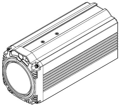
8 1. Introduction The BC-200 Block Camera is a 4K (3840x2160, QFHD) camera with an infra-red remote control. It can be used for 4K high quality shooting in an environment where space is limited. The video resolutions supported are 2160p29.97 and 2160p25. The BC-200 provides 12x optical focus, and SDI and HDMI video output interfaces. A tally light indicator sits above the BC-200 camera lens. The BC-200 supports SONY VISCA control protocol so that the camera can be controlled via RS-422 or DVIP interface. Features Lens: 1/2.3 type Exmor R CMOS 12x optical zoom, f = 3.9 mm (Wide) to 46.8 mm (Tele), F1.8 to F2.0 Supported 4K formats: (3,840 x 2,160, QFHD) 2160p/29.97, 2160p/25 Supported HD formats: 1080p/59.94/50, 1080i/59.94/50, 720p/59.94/50 Video Output: 2 HDMI (Simultaneous) Tally LED Design (RS-422/ DVIP Operation) Supports SONY VISCA Protocol Supports DVIP and RS-422 Control Protocol 8

9 2. System Diagram 9

10 3. Connections Front View IR Receiver Tally Light Lens Receives signal from the IR remote control. As the camera is booting the tally light stays solid green and turns solid red for about three seconds just before the boot is complete. The tally light remains solid green after the camera finishes booting. Camera lens for capturing images. 10
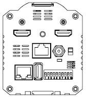
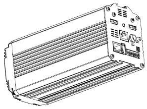
11 Rear Panel 11
12 SDI Output Video output connected to SDI monitor. HDMI Output Video output connected to HDMI port of the monitor. RS-422 Control Port Remote control port using the RS-422 control protocol. See RS-422 Control Protocol for details. 12V DC Power IN DC in socket connects the supplied 12V PSU. The connection can be secured by screwing the outer fastening ring of the DC In plug to the socket. Power Switch Turns ON/O the camera. Power LED Indicator Green: Power ON O: Power O 12
13 DVIP Control Port Remote control port using the DVIP control protocol. See DVIP Control Operation Guide for details. Firmware Upgrade Port Connects USB drive for firmware upgrade. For details, please refer to the Firmware Upgrade section. DIP Switch DIP Switch sets the camera VISCA ID, Remote Control Protocol, and Resolution, Video Mode Selection Method, and Camera ID Assignment. For details, please refer to the DIP Switch Settings section. 13
14 4. IR Remote Control Use the IR remote control that comes with the product package to operate the BC-200 Block Camera. The IR remote control functions are described in the table below. 14

15 No Item Description 1 Reset Press RESET or XYZ button to return the camera lens to the default zoom position (Z:0000). 2 Group Not Applicable 3 4 Camera Select Preset Setting Select CAM1-CAM4 in a multicamera environment Press Camera Select buttons to select a camera from Camera 1 to Camera 4 in a multi-camera environment. However before using the Camera Select function, first assign an ID number (CAM 1 CAM 4) to the camera intended for remote control operation by adjusting the DIP switch located at the rear of the camera. Please refer to DIP Switch Settings section for details. Various combinations of settings (position, zoom, focus, gain control and iris control) can be saved to presets. Adjust Preset Point Adjust position, zoom, focus, gain control and iris of the camera. 15
16 5 6 7 Focus Setup Auto Focus Control Gain Control Set up Preset Point Press any of the POSITION buttons 1~50 and then press SET button. Recall saved settings Press any of the POSITION buttons 1~50 and then press PRESET button. Set up Group Scan mode Press any of the POSITION buttons 1~8 and then press GROUP button. Manually focus camera lens on a subject Press either (F) FAR button or (N) NEAR button to manually focus the camera lens onto the subject. Before using manual focus, make sure Auto Focus mode is turned off by pressing the AUTO FOCUS button. Automatically focus camera lens on a subject Press AUTO FOCUS button and camera lens will be automatically focused on the subject. Adjust Brightness Press GAIN+ button to increase the brightness or GAIN- button to decrease the brightness. Press AUTO button to activate auto Gain Control and press again to exit. 16
.")
17 8 P/T Speed Adjust Pan/ Tilt Speed Not Applicable Auto Iris Control ENTER Direction Arrows Make the subject appear brighter Adjust the iris opening (aperture), to control the amount of light coming through the lens (i.e. the "exposure"). Press IRIS+ button to enlarge the iris opening to allow more light to come in so that the subject appears brighter and press IRIS- button to shrink the iris opening to allow less light to come in so that the subject appears less bright. Press AUTO button activate auto Iris Control and press again to exit. ENTER Press ENTER key to select a particular menu option or confirm a parameter value. Browse Menu Options Press UP, DOWN, LEFT and RIGHT arrow buttons to browse the menu options or adjust parameter values. 17
18 12 Enter/ Exit Camera Menu Press the MENU button to Enter or Exit the Camera OSD Menu 13 Zoom In/Out Buttons Zoom Press either (T) TELE button to zoom in on the subject such that it appears to be close to the camera or (W) WIDE button to zoom out from the subject such that it appears to be far away from the camera. 14 Zoom Speed Buttons (4 speed selection) Adjust Zoom In/Out Speed Press the ZOOM SPEED buttons to switch to different zoom speeds (4 being the highest and 1 being the lowest). 15 Power Button Switch ON/O camera 18
19 5. OSD Menu Options On-Screen Menu allows the user to change various camera settings such as shooting conditions and the system setup. Press Menu button on the IR remote control to enter the on-screen menu as shown below. [MAIN MENU] 1: Camera Setting 2: Video Output 3: Remote Control 4: System 5: Escape 1. Camera Setting 2. Video Output Main Menu White Balance Color temperature adjustment to make the image look more natural. IRIS This is an adjustable aperture used to control the amount of light coming through the lens. The more the iris is opened, the more light it lets in and the brighter the scene will be. AGC The setting that automatically adjusts the amplification of the signal from the camera sensor. Aperture Aperture adjusts the image sharpness. Increasing the aperture setting so that the foreground and background of your images appear sharp. Selection Way This option configures how you can select the video mode. Enabling DIP SW 8 allows you to use the DIP 19
20 Sub-Options Main Options switch to set the video mode instead of the remote control. Pattern Pattern generates color bars for color calibration. 3. Remote Control Remote control settings 4. System System configuration 5. Escape Exits the MENU Camera Setting Video Output Remote Control System Escape 1. Camera Name 1. Selection Way 1. Remote Way 1. Display 2. Mirror 2. Out Mode 2. Set RS Tally Light 3. White Balance 3. Pattern 3. Set DVIP 3. Reset All 4. Focus 4. Escape 4. Set IR 4. Update Software 5. Iris 5. Escape 5. Escape 6. AGC 7. Fog Correction 8. Aperture 9. Color Gain 10. Exposure Compensation 11. Backlight Correction 12. Day/Night Mode 13. Shutter 14. Gamma Mode 15. HR Mode 16. WD Mode 17. Escape 20
21 First Level Main Options Second Level Sub-Options Third Level Parameters Fourth Level Parameters Sub-Option Descriptions NAME 1. Camera Setting 1. Camera Name 2. Mirror 3. White Balance 4. Focus DISPLAY SW POSITION ESCAPE H+V V H O MODE SMART AWB (Enabled in ATW/AWB (AUTO) mode) MWB RED COMPONENT (Enabled in MWB (Manual)) MWB BLUE COMPONENT (Enabled in MWB (Manual)) ESCAPE FOCUS MODE AF SENSITIVITY FOCUS SPEED ON/O UPPER LEFT LOWER LEFT UPPER RIGHT LOWER RIGHT ATW/AWB (AUTO) AWC (ONE PUSH) MWB (MANUAL) 3200K (INDOOR) 5600K (OUTDOOR) 4200K (FLUO) O SMART1~3 0~128~255 0~128~255 AUTO MANUAL LOW NORMAL
22 5. Iris ESCAPE IRIS MODE Manual IRIS LEVEL ESCAPE AUTO MANUAL F1.8 F2.0 F2.4 F2.8 F3.4 F4 F4.8 F5.6 F6.8 F8 F9.6 F11 F14 CLOSE AGC MODE ON/O 6. AGC DAY (COLOR) AGC MANUAL GAIN GAIN LIMIT 0dB~GAIN LIMIT in steps of 3 db 9 db 12 db 15 db 18 db 21 db 24 db 27 db 30 db 33 db ESCAPE DNR DNR(AT AGC ON) DNR LEVEL ON O
23 7. Fog Correction ESCAPE FOG CORRECTION ESCAPE ESCAPE ON/O Aperture 0~15 9.Color Gain 0~ Exposure Compensation 11. Backlight Correction 12. Day/Night Mode 13. Shutter 0~14 O/ON (This option is enabled after AGC is turned on) B/W COLOR SHUTTER SPEED ESCAPE NORMAL 1/30 1/60 1/90 1/100 1/125 1/180 1/250 1/350 1/500 1/725 1/1000 1/ Gamma Mode 15. HR Mode STANDARD MODE1 (WD O) MODE2 (WD O) ON/O (This option is enabled after 23
24 2. Video Output 3. Remote Control 16. WD Mode 17. Escape 1. Selection Way 2. Out Mode 3. Pattern 4. Escape 1. Remote Way 2. Set RS Set DVIP 4. Set IR AGC is turned on) VE O BY MENU (Set DIP8 to Off) BY SWITCH(Set DIP8 to On) 1080i i50 720p p p p p p25 O COLOR BAR RS-422, SW (Configurable DVIP, SW using DIP switch 4 ONLY) CAMERA ID BY MENU MODE BY SWITCH CAMERA ID 1~7 RS-422 BAUD RATE ESCAPE DVIP BAUD RATE ESCAPE IR GROUP ID CAM1-4 ESCAPE 5. Escape 4. System 1. Display ZOOM OSD ON/O (Configurable using DIP switch 9/10 ONLY) 24
25 5. Escape DEBUG OSD RED/GREEN GREEN 2. Tally Light RED O 3. Reset All YES/NO SW VERSION 4. Update MB CPU Software UPDATE ALL ESCAPE 5. Escape DEBUG IR OSD DEBUG CAM. OSD DEBUG RS-422 OSD DEBUG DVIP OSD DEBUG REG OSD DEBUG FRAME NO PWR ON CAM TEST ESCAPE ESCAPE V00.19c YES/NO ON/O ON/O ON/O ON/O ON/O ON/O ON/O 25
26 6. DIP Switch Settings DIP SW 1/2/3 VISCA ID ON / O / O VISCA-ID 1 O / ON / O VISCA-ID 2 ON / ON / O VISCA-ID 3 O / O / ON VISCA-ID 4 ON / O / ON VISCA-ID 5 O / ON / ON VISCA-ID 6 ON / ON / ON VISCA-ID 7 DIP SW 4 Remote Control Protocol ON DVIP O RS-422 DIP SW 5/6/7 Resolution O / O / O 1920 x 1080i59.94 O / ON / O 1280 x 720p59.94 O / O / ON 1920 x 1080p59.94 O / ON / ON 3840 x 2160p29.97 ON / O / O 1920 x 1080i50 ON / ON / O 1280 x 720p50 ON / O / ON 1920 x 1080p50 ON / ON / ON 3840 x 2160p25 DIP SW 8 Video Mode Selection Method ON ON = video mode selectable by DIP switch only O O = video mode selectable by menu DIP SW 9/10 Camera Select Function (IR Remote Control) Camera ID Assignment O / O CAM 1 ON / O CAM 2 O / ON CAM 3 ON / ON CAM 4 26
27 7. RS-422 Control Protocol 7.1 PIN Descriptions Controller BC-200 Camera GND GND 1 White/Orange White/Orange 1 GND NC 2 Orange Orange 2 NC TX- 3 White/Green White/Green 3 RX- RX- 4 Blue Blue 4 TX- RX+ 5 White/Blue White/Blue 5 TX+ TX+ 6 Green Green 6 RX+ NC 7 White/Brown White/Brown 7 NC NC 8 Brown Brown 8 NC 7.2 Control Operation Guide Overview of VISCA In VISCA, the side outputting commands, for example a computer, is called the controller, while the side receiving the commands, such as the BC-200, is called the peripheral device. The BC-200 serves as a peripheral device in VISCA. In VISCA, up to seven peripheral devices like the BRC-300/P can be connected to one controller using communication conforming to the RS-232C/RS-422 standard. The parameters of RS-232C/RS-422 are as follows. 27
28 Communication speed: bps Data bits: 8 Start bit: 1 Stop bit: 1 Non parity Flow control using XON/XO and RTS/CTS, etc., is not supported. The address of the controller is fixed at 0. The addresses of peripheral devices are described as follows. When the address of the controller is fixed at 0 The addresses of the peripheral devices are 1, 2, 3 in order, starting from the one nearest the controller. The address of the peripheral device is set by sending address commands during the initialization of the network. When the address of the controller is fixed at 1 through 7 The addresses of the peripheral devices will be set on a pre-selected number. Within a single system, the same number can be used only once. If an address-switch number other than 0 is to be used, change the BC-200 address switch to a different number beforehand. Each VISCA device has a VISCA IN and VISCA OUT connector. Set the DTR input (the S output of the controller) of VISCA IN to H when controlling VISCA equipment from the controller. Fig. 1 VISCA network configuration 28
29 7.2.2 VISCA Communication Specifications VISCA Packet Structure The basic unit of VISCA communication is called a packet (Fig. 2). The first byte of the packet is called the header and comprises the sender s and receiver s addresses. For example, the header of the packet sent to the BC-200 assigned address 1 from the controller (address 0) is hexadecimal 81H. The packet sent to the BC-200 assigned address 2 is 82H. In the command list, as the header is 8X, input the address of the BC-200 at X. The header of the reply packet from the BC-200 assigned address 1 is 90H. The packet from the BC-200 assigned address 2 is A0H. Some of the commands for setting BC-200 units can be sent to all devices at one time (broadcast). In the case of broadcast, the header should be hexadecimal 88H. When the terminator is H, it signifies the end of the packet. Fig. 2 Packet structure Note Fig. 2 shows the packet structure, while Fig. 3 shows the actual waveform. Data flow will take place with the LSB first. 29
30 Fig. 3 Actual waveform for 1 byte Timing Chart As VISCA Command processing can only be carried out one time in a Vertical cycle, it takes the maximum 1V cycle time for an ACK/Completion to be returned. If the Command ACK/Completion communication time can be cut shorter than the 1V cycle time, then every 1V cycle can receive a Command. From this point, if 2 or more commands in a row are to be sent, wait 30
31 for the first command (for normal commands, an ACK or an error message, for query commands, an Inquiry Packet) to be carried out before sending the next one. Command and inquiry Command Sends operational commands to the BC-200. Inquiry Used for inquiring about the current state of the BC-200. Command Packet Note Inquiry 8X QQ RR QQ 1) = Command/Inquiry RR 2) = category code 1) QQ = 01 (Command), 09 (Inquiry) 2) RR = 00 (Interface), 04 (camera 1), 06 (Pan/Tilter) X = 1 to 7: BC-200 address Responses for commands and inquiries ACK message Returned by the BC-200 when it receives a command. No ACK message is returned for inquiries. Completion message Returned by the BC-200 when execution of commands or inquiries is completed. In the case of inquiry commands, it will contain reply data for the inquiry after the 3 rd byte of the packet. If the ACK message is omitted, the socket number will contain a 0. Reply Packet Note Ack X0 4Y Y = socket number Completion (Commands) X0 5Y Y = socket number Completion (Inquiries) X0 5Y Y = socket number X = 9 to F: BC-200 address
32 Error message When a command or inquiry command could not be executed or failed, an error message is returned. Error Packet Description X0 6Y 01 Message length error X0 6Y 02 Syntax error X0 6Y 03 Command buffer full X0 6Y 04 Command cancelled X0 6Y 05 No socket (to be cancelled) X0 6Y 41 Command not executable X = 9 to F: BC-200 address + 8, Y = socket number Socket number = 1 (normal) Socket number When command messages are sent to the BC-200, it is normal to send the next command message after waiting for the completion message or error message to return. As the completion message or error message also has a socket number, it indicates which command has ended. The ACK message is not returned for these commands and inquiries, and only the completion message of socket number 0 is returned VISCA Device Setting Command Before starting control of the BC-200, be sure to send the Address command and the IF_Clear command using the broadcast function. VISCA interface command IF_Clear Clears the command buffers in the BC-200 and cancels the command currently being executed. 32
33 Command Packet Reply Packet Note IF_Clear 8X X0 50 IF_Clear (broadcast) X = 1 to 7: BC-200 address (For inquiry packet) X = 9 to F: BC-200 address + 8 (For reply packet) VISCA Command/ACK Protocol Command Command Message Reply Message General Command Inquiry Command (Example) (Example) (Example) (Example) (Example) (ACK) (Completion) (Syntax Error) (Command Buffer Full) (Command Not Executable) (Completion) Comments Returns ACK when a command has been accepted, and Completion when a command has been executed. Accepted a command which is not supported or a command lacking parameters There are two commands currently being executed, and the command could not be accepted. Could not execute the command in the current mode. ACK is not returned for the inquiry command. 33
34 Address Set (Example) (Syntax Error) Accepted an incompatible command Returned the device address to +1.* Returned the same command. 8x z0 50 ACK is not returned (Completion) for this command. IF_Clear (Broadcast) IF_Clear (For x) *When the address-switch is fixed at 0, the value x in x will be indeterminate. Do not transmit the command (except Address Set, IF_Clear, CAM_POWER), when menu panel shows on the screen. In that case, clear the menu panel first using CAM_Menu Command, and then proceed VISCA Camera-Issued Messages ACK/Completion Messages Command Command Message ACK z0 4y (y: Socket No.) Completion z0 5y (y: Socket No.) z = Device address + 8 Comments Returned when the command is accepted Returned when the command has been executed Error Messages Command Command Comments Messages Syntax Error z Returned when the command format is different or when a command with illegal 34
35 Command Buffer Full No Socket Command Not Executable z z0 6y 05 (y: Socket No.) z0 6y 41 (y: Socket No.) command parameters is accepted. Indicates that two sockets are already being used (executing two commands) and the command could not be accepted when received. Returned when no command is executed in a socket specified by the cancel command, or when an invalid socket number is specified. Returned when a command cannot be executed due to current conditions. For example, when commands controlling the focus manually are received during auto focus BC-200 Commands BC-200 Command List Command Set Command Command Packet AddressSet Broadcast IF_Clear Broadcast CAM_Power On 8x Off 8x CAM_ZOOM Stop 8x Comments Address Set I/F Clear Power On/Off 35
36 Tele (Standard) 8x Wide (Standard) 8x Tele (Variable) 8x p Wide (Variable) 8x p Direct 8x p 0q 0r 0s CAM_Focus Stop 8x Far (Standard) 8x Near (Standard) 8x Direct 8x p 0q 0r 0s Auto Focus 8x Manual Focus 8x One Push 8x Trigger CAM_WB Auto 8x Indoor 8x Outdoor 8x One Push WB 8x p (=0: Slow to 7:Fast) p (=0: Slow to 7:Fast) pqrs: Zoom Position* pqrs: Focus Position* AF ON/O One Push AF Trigger Normal Auto Indoor Mode Outdoor Mode One Push WB Mode Manual 8x Manual 36
37 35 05 Control Mode One Push Trigger 8x One Push WB Trigger CAM_RGain Reset 8x Default R Gain setting Up 8x Down 8x Direct 8x p 0q CAM_BGain Reset 8x Up 8x Down 8x Direct 8x p 0q CAM_AE Full Auto 8x Manual 8x Shutter Priority 8x A R Gain Direct pq (=00 to ) Default B Gain setting B Gain Direct pq (=00 to ) Automatic exposure mode Manual control mode Shutter priority automatic exposure mode 37
38 Iris Priority 8x B Bright 8x D CAM_Shutter Reset 8x A 00 Up 8x A 02 Down 8x A 03 CAM_Iris Reset 8x B 00 Up 8x B 02 Down 8x B 03 Direct 8x B p 0q CAM_Gain Reset 8x C 00 Up 8x C 02 Down 8x C 03 Direct 8x C p 0q CAM_Backlight On 8x Iris priority automatic exposure mode Bright mode (Manual) Default Shutter setting Default Iris Setting pq: Iris Position* Default Gain setting pq: Iris Position* Back Light ON/O 38
39 Off 8x PTZ_Position Reset 8x F 00 0p Set 8x F 01 0p Recall 8x F 02 0p CAM_Menu On 8x Off 8x Pan-tilt Drive Up 8x VV WW Down 8x VV WW Left 8x VV WW Right 8x VV WW UpLeft 8x VV WW UpRight 8x VV WW DownLeft 8x VV WW Memory Number p (=0 to 50) Memory Number p (=0 to 50) Memory Number p (=0 to 50) Menu ON Menu O PanSpeed VV (=01:Slow to 18h:Fast) TiltSpeed WW (=01:Slow to 18h:Fast) 39
40 01 02 DownRight 8x VV WW Stop 8x VV WW AbsolutePosition 8x VV 00 0Y 0Y 0Y 0Y 0Y 0Z 0Z 0Z 0Z RelativePosition 8x VV 00 0Y 0Y 0Y 0Y 0Y 0Z 0Z 0Z 0Z Home 8x Reset 8x CAM_ImgFlip On 8x Off 8x Cam_PanReverse On 8x 01 7E Off 8x 01 7E Speed VV (=01: Slow to 18h:Fast) YYYYY: Pan Position* ZZZZ: Tilt Position* Speed VV (=01: Slow to 18h:Fast) YYYYY: Pan Position* ZZZZ: Tilt Position* 40
41 Cam_TiltReverse On 8x 01 7E Off 8x 01 7E Cmd_Tally On 8x 01 7E 01 0A Off 8x 01 7E 01 0A Cmd_PT_M_Speed Preset PT Speed 8x 01 7E 01 0B 0p 0q *See the section under VISCA Command Setting Values BC-200 Inquiry Command List Inquiry Command Command Packet Inquiry Packet CAM_PowerInq 8x y y CAM_ZoomPosInq 8x y0 50 0p 0q 0r 0s CAM_FocusModeI 8x y nq When Power is on, return to off. p: Memory number (=0 to 50) q: Speed (=1 to 18:fast) Comments On Off (Standby) pqrs: Zoom Position Auto Focus 41
42 y CAM_FocusPosInq 8x y0 50 0p 0q 0r 0s CAM_WBModeInq 8x y y y y y CAM_RGainInq 8x y p 0q CAM_BGainInq 8x y p 0q CAM_AEModeInq 8x y y y0 50 0A y0 50 0B CAM_ShutterPosI 8x A y nq 00 0p 0q CAM_IrisPosInq 8x B y p 0q Manual Focus pqrs: Focus Position Auto Indoor Outdoor One Push WB Manual pq: R Gain pq: B Gain Full Auto Manual Shutter Priority Iris Priority pq: Shutter Position pq: Iris Position 42
43 CAM_GainPosInq 8x C y p 0q CAM_BackLightM 8x y odeinq y CAM_MemoryInq 8x F y0 50 pp CAM_MENUInq 8x y y CAM_VersionInq 8x y0 50 mn pq 3r 3s 3t 3u 3a 3b 3c 3w 3x 3y 3z CAM_ImgFlipInq 8x y y CAM_PanReverseI 8x 09 7E y nq y pq: Gain Position On Off pp: Memory number for PTZ last operated* On Off mnpq: Model Code (0202) rstu: MCPU version abc: FPGA code version wxyz: MCTL version On Off On Off 43
44 CAM_TiltReverseI nq 8x 09 7E y y PanTilt_Status 8x y0 50 pq rs PanTilt_Max_Spee d 8x y0 50 pq rs PanTilt_Position 8x y0 50 0p 0q 0r 0s 0t 0u 0v 0w 0x Tally 8x 09 7E 01 0A y y PanTilt_Memory_ Speed 8x 09 7E 01 0B 0p y0 50 0q *See the section under VISCA Command Setting Values On Off pqrs: PanTilt Status pq: Pan Max Speed, rs: Tilt Max Speed pqrst: Pan Position uvwx: Tilt Position On Off p: Preset No. 0-50, qq: Speed 1-18 (h) 44
45 8. DVIP Control Operation Guide 8.1 Physical Layer Control Interface: Ethernet Communication Speed: 10/100Mbps Control Protocol: TCP/IP 8.2 General Connection Information By default, the DVIP is configured to operate in DHCP mode. User is allowed to re- configure to static IP address. TCP/IP Control port numbers TCP port: 5002 UDP port: Packet Data Control Command Packet (TCP) Byte (8 bits) Descriptions 0 Packet Length High Byte 1 Packet Length Low Byte 2 Command_Data [0] 513 Command_Data [511] Broadcast Packet Byte (8 bits) Descriptions 0 Packet Length High Byte 1 Packet Length Low Byte 2 0x80 3 Command 4 Parameter Parameter
46 Broadcast Command List Request TCP/IP information Command Issue to DVIP device Request TCP/IP information, include DHCP mode, DHCP Host name, IP address, Netmask, MAC address, Gateway, Primary DNS, Secondary DNS Command 0x00 Parameter 1 0x45 Parameter 2 0x54 Parameter 3 0x48 Parameter 4 0x5F Parameter 5 0x52 Parameter 6 0x45 Parameter 7 0x51 Command Return from DVIP device Length Descriptions 1 Byte Data Length High Byte 1 Byte Data Length Low Byte 1 Byte 0x80 1 Byte 0x00 1 Byte DHCP; 0: Disable; 1: Enable 16 Bytes DHCP Host name (15 bytes max) + Null (0x00) terminated 6 Bytes MAC Address 4 Bytes IP Address 4 Bytes Netmask 4 Bytes Gateway 4 Bytes Primary DNS address 4 Bytes Secondary DNS address 46
47 Broadcast Command List Request specific DVIP device firmware revision Command Issue to DVIP device Request DVIP Firmware Revision Command 0x01 Parameter 1 DVIP MAC address [0] Parameter 2 DVIP MAC address [1] Parameter 3 DVIP MAC address [2] Parameter 4 DVIP MAC address [3] Parameter 5 DVIP MAC address [4] Parameter 6 DVIP MAC address [5] Parameter 7 0x46 Parameter 8 0x57 Parameter 9 0x56 Parameter 10 0x45 Parameter 11 0x52 Parameter 12 0x5F Parameter 13 0x52 Parameter 14 0x45 Parameter 15 0x51 Command Return from DVIP device Length Descriptions 1 Byte 0x00 (Data Length High Byte) 1 Byte 0x06 (Data Length Low Byte) 1 Byte 0x80 1 Byte 0x01 1 Byte Firmware Revision Major Number 1 Byte Firmware Revision Minor Number 47
48 Broadcast Command List Set DHCP Mode Command Issue to DVIP device Set DHCP Mode Command 0x02 Parameter 1 DVIP MAC address [0] Parameter 2 DVIP MAC address [1] Parameter 3 DVIP MAC address [2] Parameter 4 DVIP MAC address [3] Parameter 5 DVIP MAC address [4] Parameter 6 DVIP MAC address [5] Parameter 7 0x53 Parameter 8 0x45 Parameter 9 0x54 Parameter 10 0x5F Parameter 11 0x44 Parameter 12 0x48 Parameter 13 0x43 Parameter 14 0x50 Parameter 15 0x4D Parameter 16 0x4F Parameter 17 0x44 Parameter 18 0x45 Parameter 19 0x00: Disable; 0x01: Enable Command Return from DVIP device Length Descriptions 1 Byte 0x00 (Data Length High Byte) 1 Byte 0x06 (Data Length Low Byte) 1 Byte 0x80 1 Byte 0x02 1 Byte 0x06 (ACK) or 0x15 (NACK) 48
49 Broadcast Command List Set IP Address Command Issue to DVIP device Set IP Address Command 0x03 Parameter 1 DVIP MAC address [0] Parameter 2 DVIP MAC address [1] Parameter 3 DVIP MAC address [2] Parameter 4 DVIP MAC address [3] Parameter 5 DVIP MAC address [4] Parameter 6 DVIP MAC address [5] Parameter 7 0x53 Parameter 8 0x45 Parameter 9 0x54 Parameter 10 0x5F Parameter 11 0x49 Parameter 12 0x50 Parameter 13 0x41 Parameter 14 0x44 Parameter 15 0x52 Parameter 16 IP_Address [0] Parameter 17 IP_Address [1] Parameter 18 IP_Address [2] Parameter 19 IP_Address [3] Parameter 20 Gateway [0] Parameter 21 Gateway [1] Parameter 22 Gateway [2] Parameter 23 Gateway [3] Command Return from DVIP device Length Descriptions 1 Byte 0x00 (Data Length High Byte) 1 Byte 0x06 (Data Length Low Byte) 1 Byte 0x80 1 Byte 0x03 49
50 1 Byte 0x06 (ACK) or 0x15 (NACK) Broadcast Command List Reset to Factory Default Command Issue to DVIP device Reset to Factory Default Command 0x04 Parameter 1 DVIP MAC address [0] Parameter 2 DVIP MAC address [1] Parameter 3 DVIP MAC address [2] Parameter 4 DVIP MAC address [3] Parameter 5 DVIP MAC address [4] Parameter 6 DVIP MAC address [5] Parameter 7 0x52 Parameter 8 0x45 Parameter 9 0x53 Parameter 10 0x45 Parameter 11 0x54 Command Return from DVIP device Length Descriptions 1 Byte 0x00 (Data Length High Byte) 1 Byte 0x06 (Data Length Low Byte) 1 Byte 0x80 1 Byte 0x04 1 Byte 0x06 (ACK) or 0x15 (NACK) Broadcast Command List Get Device Model Number Command Issue to DVIP device Get Device Model Number Command 0x05 Parameter 1 DVIP MAC address [0] Parameter 2 DVIP MAC address [1] Parameter 3 DVIP MAC address [2] Parameter 4 DVIP MAC address [3] 50
51 Parameter 5 DVIP MAC address [4] Parameter 6 DVIP MAC address [5] Parameter 7 0x47 Parameter 8 0x45 Parameter 9 0x54 Parameter 10 0x5F Parameter 11 0x4D Parameter 12 0x4F Parameter 13 0x44 Parameter 14 0x45 Parameter 15 0x4C Parameter 16 0x5F Parameter 17 0x4E Parameter 18 0x41 Parameter 19 0x4D Parameter 20 0x45 Command Return from DVIP device Length Descriptions 1 Byte 0x00 (Data Length High Byte) 1 Byte 0x06 (Data Length Low Byte) 1 Byte 0x80 1 Byte 0x04 16 Bytes Device Model Number is 16 Bytes maximum; use null padding (0x00) if it is less than 16 bytes. UDP Packet Byte (8 bits) Descriptions 0 Packet Length High Byte 1 Packet Length Low Byte 2 0x81 3 Command Parameter 1 Parameter
52 UDP Command List Request TCP/IP information Command Issue to DVIP device Request TCP/IP information, include DHCP mode, DHCP Host name, IP address, Netmask, MAC address, Gateway, Primary DNS, Secondary DNS Command 0x00 Parameter 1 0x45 Parameter 2 0x54 Parameter 3 0x48 Parameter 4 0x5F Parameter 5 0x52 Parameter 6 0x45 Parameter 7 0x51 Command Return from DVIP device Length Descriptions 1 Byte Data Length High Byte 1 Byte Data Length Low Byte 1 Byte 0x80 1 Byte 0x00 1 Byte DHCP; 0: Disable; 1: Enable 16 Bytes DHCP Host name (15 bytes max) + Null (0x00) terminated 6 Bytes MAC Address 4 Bytes IP Address 4 Bytes Netmask 4 Bytes Gateway 4 Bytes Primary DNS address 4 Bytes Secondary DNS address UDP Command List Request specific DVIP device firmware revision Command Issue to DVIP device Request DVIP Firmware Revision Command 0x01 52
53 Parameter 1 Parameter 2 Parameter 3 Parameter 4 Parameter 5 Parameter 6 Parameter 7 Parameter 8 Parameter 9 0x46 0x57 0x56 0x45 0x52 0x5F 0x52 0x45 0x51 Command Return from DVIP device Length Descriptions 1 Byte 0x00 (Data Length High Byte) 1 Byte 0x06 (Data Length Low Byte) 1 Byte 0x80 1 Byte 0x01 1 Byte Firmware Revision Major Number 1 Byte Firmware Revision Minor Number UDP Command List Set DHCP Mode Command Issue to DVIP device Set DHCP Mode Command 0x02 Parameter 1 0x53 Parameter 2 0x45 Parameter 3 0x54 Parameter 4 0x5F Parameter 5 0x44 Parameter 6 0x48 Parameter 7 0x43 Parameter 8 0x50 Parameter 9 0x4D Parameter 10 0x4F Parameter 11 0x44 53
54 Parameter 12 Parameter 13 0x45 0x00: Disable; 0x01: Enable Command Return from DVIP device Length Descriptions 1 Byte 0x00 (Data Length High Byte) 1 Byte 0x06 (Data Length Low Byte) 1 Byte 0x81 1 Byte 0x02 1 Byte 0x06 (ACK) or 0x15 (NACK) UDP Command List Set IP Address & Gateway Address Command Issue to DVIP device Set IP Address Command 0x03 Parameter 1 0x53 Parameter 2 0x45 Parameter 3 0x54 Parameter 4 0x5F Parameter 5 0x49 Parameter 6 0x50 Parameter 7 0x41 Parameter 8 0x44 Parameter 9 0x52 Parameter 10 IP_Address [0] Parameter 11 IP_Address [1] Parameter 12 IP_Address [2] Parameter 13 IP_Address [3] Parameter 14 Gateway [0] Parameter 15 Gateway [1] Parameter 16 Gateway [2] Parameter 17 Gateway [3] 54
55 Command Return from DVIP device Length Descriptions 1 Byte 0x00 (Data Length High Byte) 1 Byte 0x05 (Data Length Low Byte) 1 Byte 0x81 1 Byte 0x03 1 Byte 0x06 (ACK) or 0x15 (NACK) UDP Command List Reset to Factory Default Command Issue to DVIP device Reset to Factory Default Command 0x04 Parameter 1 0x52 Parameter 2 0x45 Parameter 3 0x53 Parameter 4 0x45 Parameter 5 0x54 Command Return from DVIP device Length Descriptions 1 Byte 0x00 (Data Length High Byte) 1 Byte 0x06 (Data Length Low Byte) 1 Byte 0x81 1 Byte 0x04 1 Byte 0x06 (ACK) or 0x15 (NACK) UDP Command List Set DHCP Host Name Command Issue to DVIP device Set DHCP Host Name Command 0x09 Parameter 1 0x53 Parameter 2 0x45 Parameter 3 0x54 Parameter 4 0x5F 55
56 Parameter 5 Parameter 6 Parameter 7 Parameter 8 Parameter 9 Parameter 10 Parameter 11 Parameter 12 Parameter 13 Parameter 0x44 0x48 0x43 0x50 0x4E 0x41 0x4D 0x45 Name (ASCII), 15 bytes Max. Null (0x00) terminated Command Return from DVIP device Length Descriptions 1 Byte 0x00 (Data Length High Byte) 1 Byte 0x05 (Data Length Low Byte) 1 Byte 0x81 1 Byte 0x09 1 Byte 0x06 (ACK) or 0x15 (NACK) UDP Command List Set Netmask Command Issue to DVIP device Set Netmask Command 0x0B Parameter 1 0x53 Parameter 2 0x45 Parameter 3 0x54 Parameter 4 0x5F Parameter 5 0x4E Parameter 6 0x45 Parameter 7 0x54 Parameter 8 0x4D Parameter 9 0x41 Parameter 10 0x53 56
57 Parameter 11 0x4B Parameter 12 Net_Mask [0] Parameter 13 Net_Mask [1] Parameter 14 Net_Mask [2] Parameter 15 Net_Mask [3] Command Return from DVIP device Length Descriptions 1 Byte 0x00 (Data Length High Byte) 1 Byte 0x05 (Data Length Low Byte) 1 Byte 0x81 1 Byte 0x0B 1 Byte 0x06 (ACK) or 0x15 (NACK) UDP Command List Set Gateway Address Command Issue to DVIP device Set Gateway Address Command 0x0C Parameter 1 0x53 Parameter 2 0x45 Parameter 3 0x54 Parameter 4 0x5F Parameter 5 0x47 Parameter 6 0x41 Parameter 7 0x54 Parameter 8 0x45 Parameter 9 0x57 Parameter 10 0x41 Parameter 11 0x59 Parameter 12 Gateway [0] Parameter 13 Gateway [1] Parameter 14 Gateway [2] Parameter 15 Gateway [3] 57
58 Command Return from DVIP device Length Descriptions 1 Byte 0x00 (Data Length High Byte) 1 Byte 0x05 (Data Length Low Byte) 1 Byte 0x81 1 Byte 0x0C 1 Byte 0x06 (ACK) or 0x15 (NACK) UDP Command List Set Primary DNS Address Command Issue to DVIP device Set Gateway Address Command 0x0D Parameter 1 0x53 Parameter 2 0x45 Parameter 3 0x54 Parameter 4 0x5F Parameter 5 0x50 Parameter 6 0x52 Parameter 7 0x49 Parameter 8 0x44 Parameter 9 0x4E Parameter 10 0x53 Parameter 11 Primary_DNS_IP [0] Parameter 12 Primary_DNS_IP [1] Parameter 13 Primary_DNS_IP [2] Parameter 14 Primary_DNS_IP [3] Command Return from DVIP device Length Descriptions 1 Byte 0x00 (Data Length High Byte) 1 Byte 0x05 (Data Length Low Byte) 1 Byte 0x81 1 Byte 0x0D 1 Byte 0x06 (ACK) or 0x15 (NACK) 58
59 UDP Command List Set Secondary DNS Address Command Issue to DVIP device Set Gateway Address Command 0x0E Parameter 1 0x53 Parameter 2 0x45 Parameter 3 0x54 Parameter 4 0x5F Parameter 5 0x53 Parameter 6 0x45 Parameter 7 0x43 Parameter 8 0x44 Parameter 9 0x4E Parameter 10 0x53 Parameter 11 Secondary_DNS_IP [0] Parameter 12 Secondary _DNS_IP [1] Parameter 13 Secondary _DNS_IP [2] Parameter 14 Secondary _DNS_IP [3] Command Return from DVIP device Length Descriptions 1 Byte 0x00 (Data Length High Byte) 1 Byte 0x05 (Data Length Low Byte) 1 Byte 0x81 1 Byte 0x0E 1 Byte 0x06 (ACK) or 0x15 (NACK) UDP Command List Initial DVIP Configuration Command Issue to DVIP device Initial DVIP Configuration Command 0x0F Parameter 1 0x49 Parameter 2 0x4E 59
60 Parameter 3 0x49 Parameter 4 0x54 Parameter 5 0x5F Parameter 6 0x45 Parameter 7 0x32 Parameter 8 0x50 Parameter 9 DHCP_Mode Parameter 10 DHCP_Host_Name [0-14] (ASCII), 15 Bytes Max. Parameter N Null (0x00) Parameter N+1 MAC_Address [0-3] Parameter N+5 IP_Address [0-3] Parameter N+9 Gateway_IP [0-3] Parameter N+13 Net_Mask [0-3] Parameter N+17 Primary_DNS_IP [0-3] Parameter N+21 Secondary_DNS_IP [0-3] Command Return from DVIP device Length Descriptions 1 Byte 0x00 (Data Length High Byte) 1 Byte 0x05 (Data Length Low Byte) 1 Byte 0x81 1 Byte 0x0F 1 Byte 0x06 (ACK) or 0x15 (NACK) 60
61 9. Firmware Upgrade 1) Copy MB CPU image files into the root directory of a USB hard drive (<16 GB) and insert it into the USB Upgrade port (You may use a USB extension cord). 2) Open the OSD menu using IR remote control by pressing the MENU button. 3) Browse to => 4: SYSYEM => 4: UPDATE SOFTWARE => 3: UPDATE ALL =>YES => ENTER 4) Wait for another five minutes until the following lines appear on the screen - Updated MCPU =>OK The OSD will flash Write OK/Power ON Again. Note: it takes approximately 5-7 minutes to complete the update. 5) Turn off the device by unplugging the power cord. Plug the power cord back into the socket and then turn on the device again. 6) FW Update is complete. 61
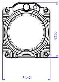
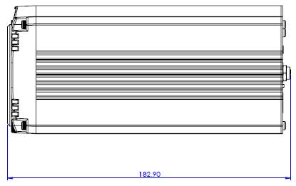
62 10. Dimensions All measurements in millimeters (mm) 62
63 11. Specifications Image Pickup Element Effective Picture Elements Signal System Min. Illumination Recommended Illumination Gain Shutter Speed Backlight Compensation Exposure Control White Balance Focusing System Video 1/2.3 type Exmor CMOS sensor Approx Mega pixels 4K (3,840 x 2,160, QFHD) 2160p / 29.97, 2160p/25 HD: 1080p59.94/ i59.94/50 720p59.94/50 50%, High Sensitivity Mode Color : 0.75 lx (F1.8, AGC ON, 1/30 sec) 50%, Normal Mode: Color: 3 lx (F1.8, AGC ON, 1/30 sec) 100 lx 100,000 lx Auto / Manual (0 to 33 db) Max. Gain Limit (9 to 33 db) 1/25 (1/30), 1/50 (1/60), 1/75(1/90), 1/100, 1/120 (1/125), 1/150(1/180), 1/215( 1/250), 1/300(1/350), 1/425(1/500), 1/600(1/725), 1/1000, 1/1250(1/1500) sec Yes Auto, Manual, Priority Mode (shutter priority & iris priority) Bright, EV compensation Auto, Indoor, Outdoor, Sodium Vapor Lamp, One-push, Manual Auto (Sensitivity: normal, low), One- Push AF, Manual, Zoom Trigger AF 63
64 Lens Lens Type 12x Optical Zoom, f = 3.9 mm (WIDE) to 46.8 mm (TELE) F1.8 to F2.0 Digital Zoom 12x Angle of View (Horizontal) 70.7 degrees (WIDE END) to 6.4 degrees (TELE END) Minimum Object Distance 10 mm (WIDE END) to 1,500 mm (TELE END) (Default: 300 mm) Video Output Video Output HDMI x 2 Control Protocol VISCA / DVIP Protocol Remote Control RS-422 & DVIP by RJ-45 interface F/W Update USB 2.0 IR Control One IR controller Others Operating Temperature 0 C ~ 50 C Storage Temperature - 10 C ~ 60 C Operating Humidity: 10 % to 80 % (non-condensing) Power DC 12V 1A Power Consumption 10W 71.4 x 82.6 x 182.9(mm) (without Dimensions (W x H x D) Tripod mount adapter) 71.4 x 95.2 x 182.9(mm) (with Tripod mount adapter) Net Weight 0.936Kg(w/tripod mount adapter) 64

65 Service & Support It is our goal to make your products ownership a satisfying experience. Our supporting staff is available to assist you in setting up and operating your system. Please refer to our web site for answers to common questions, support requests or contact your local office below. China Shanghai Datavideo Technologies China Co 601,Building 10,No.1228, Rd.Jiangchang, Jingan District,Shanghai Tel: Fax: service@datavideo.cn Hong Kong Datavideo Hong Kong Ltd G/F.,26 Cross Lane Wanchai, Hong Kong Tel: Fax: info@datavideo.com.hk Singapore Datavideo Technologies (S) PTE Ltd No. 178 Paya Lebar Road #06-03 Singapore Tel: Fax: sales@datavideo.sg China Beijing Datavideo Technologies China Co No. 812, Building B, Wankai Center, No.316, Wan Feng Road, Fengtai District, Beijing, China Tel: Fax: service@datavideo.cn India Noida Datavideo India Noida A-132, Sec-63,Noida , India Tel: Fax: sales@datavideo.in Taiwan Datavideo Technologies Co. Ltd 10F. No. 176, Jian 1st Rd.,Chung Ho District, New Taipei City 235, Taiwan Tel: Fax: service@datavideo.com.tw China Chengdu China Fuzhou Datavideo Technologies China Co B-823,Meinian square,no.1388, Middle of Tianfu Avenue,Gaoxin District, Chengdu,Sichuan Tel: Fax: service@datavideo.cn Datavideo Technologies China Co A Room,No.8, Aojiang Road, Taijiang District,Fuzhou,Fujian,China Tel: , Fax: service@datavideo.cn India Kochi Netherlands Datavideo India Kochi 2nd Floor- North Wing, Govardhan Building, Opp. NCC Group Headquaters, Chittoor Road, Cochin Tel: Fax: sales@datavideo.in Datavideo Technologies Europe BV Floridadreef AM Utrecht, The Netherlands Tel: Fax: info@datavideo.nl United States United Kingdom Datavideo Corporation 7048 Elmer Avenue. Whittier, CA 90602, U.S.A. Tel: Fax: sales@datavideo.com Datavideo UK Limited Brookfield House, Brookfield Industrial Estate, Peakdale Road, Glossop, Derbyshire, SK13 6LQ Tel: Fax: sales@datavideo.co.uk China Jinan Datavideo Technologies China Co 902, No. 1 business building, Xiangtai Square, No. 129, Yingxiongshan Road, Shizhong District, Jinan City, Shandong Province, China Tel: service@datavideo.cn Singapore Datavideo Visual Technology(S) Pte Ltd No. 178 Paya Lebar Road #06-07 Singapore Tel: Fax: info@datavideovirtualset.com France Datavideo France s.a.r.l. Cité Descartes 1, rue Albert Einstein Champs sur Marne Marne la Vallée cedex 2 Tel: Fax: info@datavideo.fr Please visit our website for latest manual update. All the trademarks are the properties of their respective owners. Datavideo Technologies Co., Ltd. All rights reserved 2018 Jul
BC-200 Instruction Manual
 4K BLOCK CAMERA BC-200 Instruction Manual Table of Contents FCC COMPLIANCE STATEMENT... 4 WARNINGS AND PRECAUTIONS... 4 WARRANTY... 5 STANDARD WARRANTY... 5 THREE YEAR WARRANTY... 6 DISPOSAL... 7 1. INTRODUCTION...
PTZ and Block Camera Control Protocol. JAN 15 th, 2019
 Rev 1.8 PTZ and Block Camera Control Protocol JAN 15 th, 2019 Model: BC-80, BC-80T, BC-200, BC-200T, PTC-150, PTC-150T, PTC-200, PTC-200T Datavideo Technologies Datavideo PTZ/Block Camera VISCA Commands
BC-200T Instruction Manual
 4K HDBaseT BLOCK CAMERA BC-200T Instruction Manual Table of Contents FCC COMPLIANCE STATEMENT... 4 WARNINGS AND PRECAUTIONS... 4 WARRANTY... 6 STANDARD WARRANTY... 6 THREE YEAR WARRANTY... 6 DISPOSAL...
BC-80 BLOCK CAMERA. Instruction Manual
 BC-80 BLOCK CAMERA Instruction Manual Table of Contents FCC COMPLIANCE STATEMENT... 4 WARNINGS AND PRECAUTIONS... 4 WARRANTY... 5 STANDARD WARRANTY... 5 THREE YEAR WARRANTY... 6 DISPOSAL... 7 1. INTRODUCTION...
AUDIO DELAY BOX WITH MICROPHONE INPUT AD-100M. Instruction manual.
 AUDIO DELAY BOX WITH MICROPHONE INPUT AD-100M Instruction manual www.datavideo.com Table of Contents FCC COMPLIANCE... 3 WARNINGS AND PRECAUTIONS... 3 WARRANTY... 4 STANDARD WARRANTY... 4 THREE YEAR WARRANTY...
Table of Contents. Standard Warranty 5. Two Year Warranty Remote Control Functions On-Screen Menu Step 1 DIP Switch Setting 21
 1 Table of Contents Warnings and Precautions 4 Warranty 5 Standard Warranty 5 Two Year Warranty 5 Disposal 5 1. Product Overview 6 2. Features 6 3. Location and Function of Parts 7 4. System Diagram 8
PTZ CAMERA CONTROL UNIT RMC-190 Instruction manual
 PTZ CAMERA CONTROL UNIT RMC-190 Instruction manual www.datavideo.com Table of Contents FCC COMPLIANCE STATEMENT... 3 WARNINGS AND PRECAUTIONS... 3 WARRANTY... 4 STANDARD WARRANTY... 4 THREE YEAR WARRANTY...
PTZ CAMERA CONTROL UNIT. RMC-180 Instruction manual.
 PTZ CAMERA CONTROL UNIT RMC-180 Instruction manual www.datavideo.com Table of Contents FCC COMPLIANCE STATEMENT... 3 WARNINGS AND PRECAUTIONS... 3 WARRANTY... 4 STANDARD WARRANTY... 4 THREE YEAR WARRANTY...
PTC-150/ PTC-150W Instruction Manual
 HD/SD-SDI PTZ CAMERA PTC-150/ PTC-150W Instruction Manual Table of Contents FCC COMPLIANCE STATEMENT... 4 WARNINGS AND PRECAUTIONS... 4 WARRANTY... 6 STANDARD WARRANTY... 6 THREE YEAR WARRANTY... 6 DISPOSAL...
4K PTZ CAMERA PTC-200 Instruction Manual
 4K PTZ CAMERA PTC-200 Instruction Manual Table of Contents FCC Compliance Statement 4 Warnings and Precautions 4 Warranty 5 Standard Warranty 5 Three Year Warranty 6 Disposal 6 1. Product Overview 7 2.
HD/SD-SDI HDBaseT PTZ CAMERA PTC-150T/ PTC-150TW. Instruction Manual.
 HD/SD-SDI HDBaseT PTZ CAMERA PTC-150T/ PTC-150TW Instruction Manual www.datavideo.com Table of Contents FCC COMPLIANCE STATEMENT... 4 WARNINGS AND PRECAUTIONS... 4 WARRANTY... 5 STANDARD WARRANTY... 5
b. Time Setting c. Volume Setting d. Backlight Setting e. Sleep Setting f. Pin Setting g. Joystick Calibration...
 0 Warnings and Precautions... 2 Warranty... 3 Disposal... 3 1. Product Overview... 4 2. Features... 4 3. Functions... 4 4. System Diagram... 7 5. Setting Menu... 9 6. Menu operation... 10 a. Camera Setting...
HD/SD-SDI HDBaseT PTZ CAMERA PTC-150T/ PTC-150TW. Instruction Manual.
 HD/SD-SDI HDBaseT PTZ CAMERA PTC-150T/ PTC-150TW Instruction Manual www.datavideo.com Table of Contents TABLE OF CONTENTS... 2 FCC COMPLIANCE STATEMENT... 4 WARNINGS AND PRECAUTIONS... 4 WARRANTY... 5
Remote Production Solutions HD/SD PTZ Camera/Controller/Switcher. Lecture Recording Conference Meeting Automated Studio Remote Production
 Remote Production Solutions 2015 HD/SD PTZ Camera/Controller/Switcher Lecture Recording Conference Meeting Automated Studio Remote Production 3G PTC-120 PTZ camera is designed for lecture recording, conference
HD/SD-SDI HDBaseT PTZ CAMERA PTC-150T/ PTC-150TW. Instruction Manual.
 HD/SD-SDI HDBaseT PTZ CAMERA PTC-150T/ PTC-150TW Instruction Manual www.datavideo.com Table of Contents FCC COMPLIANCE STATEMENT... 4 WARNINGS AND PRECAUTIONS... 4 WARRANTY... 6 STANDARD WARRANTY... 6
CONTENTS PTC-200 4K PTZ CAMERA. PTC-150T HDBaseT PTZ NH-100 LOW LIGHT PRODUCTION CAMERA CAMERA BC-80 HD BLOCK CAMERA CONTROL BC-50 HD BLOCK CAMERA
 CAMERAS CONTENTS 3 7 9 NH-100 LOW LIGHT PRODUCTION CAMERA PTC-150 HD PTZ CAMERA PTC-150T HDBaseT PTZ CAMERA PTC-200 4K PTZ CAMERA RMC180 CAMERA CONTROL BC-80 HD BLOCK CAMERA BC-50 HD BLOCK CAMERA BC-200
MULTI-CAMERA CONTROL UNIT. MCU-200P Instruction Manual.
 MULTI-CAMERA CONTROL UNIT MCU-200P Instruction Manual www.datavideo.com Table of Contents FCC COMPLIANCE STATEMENT... 3 WARNINGS AND PRECAUTIONS... 3 WARRANTY... 4 STANDARD WARRANTY... 4 THREE YEAR WARRANTY...
MCU-100P Instruction Manual
 MULTI-CAMERA CONTROL UNIT MCU-100P Instruction Manual Table of Contents FCC COMPLIANCE STATEMENT... 3 WARNINGS AND PRECAUTIONS... 3 WARRANTY... 4 STANDARD WARRANTY... 4 THREE YEAR WARRANTY... 4 DISPOSAL...
WARNINGS AND PRECAUTIONS... 3 PACKING LIST... 5 FRONT PANEL... 5 REAR PANEL... 6 MENU SETTINGS... 7 EXAMPLE SETUP SPECIFICATIONS...
 AUDIO DELAY sax AD-1 aam Quick Start Guide WARNINGS AND PRECAUTIONS... 3 PACKING LIST... 5 FRONT PANEL... 5 REAR PANEL... 6 MENU SETTINGS... 7 EXAMPLE SETUP... 11 SPECIFICATIONS... 11 SERVICE & SUPPORT...
Remote Production Solutions HD/SD PTZ Camera / Controller. Lecture Recording Conference Meeting Automated Studio Remote Production
 Remote Production Solutions 2016 HD/SD / Controller Lecture Recording Conference Meeting Automated Studio Remote Production 3G PTC-120 PTZ camera is designed for lecture recording, conference meetings
PTZ Camera. for HDVS-300 Soft Codec Conferencing System. Application Programming Interface. Atlona Manuals Accessories AT-HDVS-CAM
 PTZ Camera for HDVS-300 Soft Codec Conferencing System Application Programming Interface AT-HDVS-CAM Atlona Manuals Accessories Version Information Version Release Date Notes 1 4/18 Initial release AT-HDVS-CAM
Warnings and Precautions
 Warnings and Precautions 1. Read all of these warnings and save them for later reference. 2. Follow all warnings and instructions marked on this unit. 3. Unplug this unit from the wall outlet before cleaning.
Network Camera. Quick Guide DC-B1203X. Powered by
 Network Camera Quick Guide DC-B1203X Powered by Safety Precautions English WARNING RISK OF ELECTRIC SHOCK DO NOT OPEN WARNING: TO REDUCE THE RISK OF ELECTRIC SHOCK, DO NOT REMOVE COVER (OR BACK). NO USER-SERVICEABLE
Remote Production Solutions HD/SD PTZ Camera / Controller. Lecture Recording Conference Meetings Automated Studios Remote Production
 Remote Production Solutions 2016 2017 HD/SD PTZ Camera / Controller Lecture Recording Conference Meetings Automated Studios Remote Production NEW Product 2 PTC-150T PTZ Camera with HDBaseT Extremely fast
H.264 USB RECORDER HDR-1. Instruction Manual
 H.264 USB RECORDER HDR-1 Instruction Manual Table of Contents FCC COMPLIANCE STATEMENT... 5 WARNINGS AND PRECAUTIONS... 5 WARRANTY... 6 STANDARD WARRANTY... 6 THREE YEAR WARRANTY... 7 DISPOSAL... 7 CHAPTER
HD SDI 1080P ICR OSD 42 IR Vandal Dome Camera
 HDVDX42-4AVF HD SDI 1080P ICR OSD 42 IR Vandal Dome Camera Optional Bracket MB-4VD USER MANUAL FEATURES SDI 1080P - 1920 x 1080, 30fps, 2.0 Megapixel 1/2.8 2.0 Megapixel Progressive Scan CMOS 3.3mm~12mm
HD SDI 1080p WDR DNR 24 IR OSD Bullet Camera
 HD21B24-940 HD SDI 1080p WDR DNR 24 IR OSD Bullet Camera USER MANUAL FEATURES SDI 1080p - 1920 x 1080 1/2.9" Sony Exmor 4.0mm Fixed Lens 0.5 Lux 24 IR LED IR distance up to 50ft / 24m 700mA max 12V DC
Contents. Warnings and Precautions...3. Warranty...4. Disposal...4. Packing List...5. Introduction...5. Features...6. Example MCU-100 Set Up...
 Contents Warnings and Precautions...3 Warranty...4 Disposal...4 Packing List...5 Introduction...5 Features...6 Example MCU-100 Set Up...7 Connections and Controls...8 MCU-100 Keyboard Guide...10 How to
QIT600F1 USER'S GUIDE
 QIT600F1 USER'S GUIDE 1 IMPORTANT SAFEGUARDS Warnings: 1. Read all of these instructions. Save these instructions for later use, please. 2. Unplug this monitor from the wall outlet before cleaning. Do
Avonic AV-CON300. PTZ Camera Controller
 Avonic AV-CON300 PTZ Camera Controller User Manual Version 1.0 Update notes: Join Avonic linkedin.com/company/avonic twitter.com/avonic1 facebook.com/avonic www.avonic.eu 1 Contents Inhoud Contents...
DSLR PROMPTER TP-500 Instruction manual
 DSLR PROMPTER Instruction manual Contents FCC COMPLIANCE STATEMENT... 2 WARNINGS AND PRECAUTIONS... 2 GLASS HANDLE WITH CARE... 2 WARRANTY... 3 STANDARD WARRANTY... 3 REGISTER FOR 3 YEAR WARRANTY... 3
Datavideo DVIP Control Operation Guide
 1 Physical Layer 1.1 Control Interface : Ethernet 1.2 Communication Speed : 10/100Mbps 1.3 Control Protocol : TCP/IP 2 General Connection Information 2.1 By default the DVIP is configured to operate at
ITC-100. Users Guide. 8 Channel Intercom / Talkback System. Rev:
 ITC-100 8 Channel Intercom / Talkback System Users Guide http:// www.datavideo-tek.com Rev: 300506 Warnings and Precautions 1. Read all of these warnings and save them for later reference. 2. Follow all
EVO-TM2A EVO-TM2B Touch Screen Monitor
 User Manual Revision v1.3 Dec. 2010 EVO-TM2A EVO-TM2B Touch Screen Monitor Copyright 2010 August All Rights Reserved Manual Version 1.3 Part Number: The information contained in this document is subject
DC-D4213RX DC-D4213WRX
 Network Camera Quick Guide DC-D4213RX DC-D4213WRX Powered by Safety Precautions WARNING RISK OF ELECTRIC SHOCK DO NOT OPEN WARNING: TO REDUCE THE RISK OF ELECTRIC SHOCK, DO NOT REMOVE COVER (OR BACK).
HuddleCamHD SimplTrack
 Page1 HuddleCamHD SimplTrack Auto Tracking Camera Installation & Operation Manual Page2 Table of Contents. Precautions Safety Tips............... Page 3 What s in the Box.............. Page 3 Physical
HuddleCamHD 10X-USB2
 HuddleCamHD 10X-USB2 USB 2.0 PTZ CAMERA INSTALLATION & OPERATION MANUAL Please check HUDDLECAMHD.com for the most up to date version of this document Precautions. Safety Tips. Please read this manual carefully
C (1) Color Video Camera. Command List BRC-X1000/H800/H Sony Corporation
 Color Video Camera. Command List BRC-X1000/H800/H Sony Corporation") C--- () Color Video Camera Command List BRC-X/H8/H78 Sony Corporation Table of Contents VISCA Commands... Overview of VISCA... VISCA Communication Specifications... VISCA Device Setting Command... VISCA
C--- () Color Video Camera Command List BRC-X/H8/H78 Sony Corporation Table of Contents VISCA Commands... Overview of VISCA... VISCA Communication Specifications... VISCA Device Setting Command... VISCA
Prestigio P371 Users manual
 Prestigio P371 Users manual 1. IMPORTANT INFORMATION WARNING: TO PREVENT FIRE OR SHOCK HAZARD, DO NOT EXPOSE THIS MONITOR TO LIQUIDS OR MOISTURE. HIGH VOLTAGE EXISTS ON THIS MONITOR. DO NOT REMOVE THE
CM-Z2212GY. Outdoor IR Speed Dome PTZ Camera
 Outdoor IR Speed Dome PTZ Camera User s Guide CM-Z2212GY 1201-1205, Sangda Mansion, High Technology Park, SAFETY PRECAUTIONS WARNING 1. Be sure to use only the standard adapter that is specified in the
Nearus USB2.0 Camera Manual NU-350-USB2PTZ-B
 Nearus USB2.0 Camera Manual NU-350-USB2PTZ-B Safety Tips Please read this manual carefully before installing the camera. Keep the camera away from violent vibration, physical stress, moisture, extreme
HuddleCamHD SimplTrack2
 Page1 HuddleCamHD SimplTrack2 Auto Tracking Camera Installation & Operation Manual Page2 Table of Contents. Precautions Safety Tips............... Page 3 What s in the Box.............. Page 3 Physical
HuddleCamHD 3x USB 2.0 PTZ CAMERA INSTALLATION & OPERATION MANUAL
 HuddleCamHD 3x USB 2.0 PTZ CAMERA INSTALLATION & OPERATION MANUAL Precautions. Safety Tips. Please read this manual carefully before using the camera. Avoid damage from stress, violent vibration or liquid
Supplied Accessories.
 Precautions. Safety Tips. Please read this manual carefully before using the camera. Avoid damage from stress, violent vibration or liquid intrusion during transportation, storage or installation. Take
VC-B10U HD Camera (USB 3.0 Camera) Installation Manual - English
 Installation Manual - English") VC-B10U HD Camera (USB 3.0 Camera) Installation Manual - English [Important] To download the latest version of Quick Start Guide, multilingual user manual, software, or driver, etc., please visit Lumens
VC-B10U HD Camera (USB 3.0 Camera) Installation Manual - English [Important] To download the latest version of Quick Start Guide, multilingual user manual, software, or driver, etc., please visit Lumens
HuddleCamHD 10x (Gen 3)
") HuddleCamHD 10x (Gen 3) USB 3.0 PTZ CAMERA INSTALLATION & OPERATION MANUAL Precautions. Safety Tips. Please read this manual carefully before using the camera. Avoid damage from stress, violent vibration
HuddleCamHD 10x (Gen 3) USB 3.0 PTZ CAMERA INSTALLATION & OPERATION MANUAL Precautions. Safety Tips. Please read this manual carefully before using the camera. Avoid damage from stress, violent vibration
Supplied Accessories.
 Precautions. Safety Tips. Please read this manual carefully before using the camera. Avoid damage from stress, violent vibration or liquid intrusion during transportation, storage or installation. Take
Version 1.0 March 2014 OLC 10.1
 User Manual Version 1.0 March 2014 OLC 10.1 Copyright 2014 All Rights Reserved Manual Version 1.0 The information contained in this document is subject to change without notice. We make no warranty of
DANNOVO HD USB 3.0 PTZ Video Conference Camera User Manual
 DANNOVO HD USB 3.0 PTZ Video Conference Camera User Manual V 2.3(ENGLISH VERSION) Please read this Manual before set up Camera, and stick to its requirements strictly for Safety reason. Suggest you save
ST-HDC2FD QUICK START GUIDE. Or contact technical
 ST-HDC2FD QUICK START GUIDE www.nacebrands.com www.securitytronix.com User Manual Thank you for purchasing our product. If there are any questions, or requests, please do not hesitate to contact the dealer
TURBO HD D7T Series Dome Camera
 TURBO HD D7T Series Dome Camera User Manual UD02018B User Manual Thank you for purchasing our product. If there are any questions, or requests, do not hesitate to contact the dealer. This manual applies
Multi-Format Digital Video Converter DAC-30 Quick Reference Guide
 Multi-Format Digital Video Converter DAC-30 Quick Reference Guide http://www.datavideo-tek.com Table of contents Warnings and Precautions ---------------------------------------------------------------
Thank you for purchasing our product. If there are any questions, or requests, please do not hesitate to contact the dealer.
 User Manual Thank you for purchasing our product. If there are any questions, or requests, please do not hesitate to contact the dealer. This manual may contain several technical incorrect places or printing
VZ-TVI-B3040MZVF 3MP Motorized VF EXIR Bullet Camera
 VZ-TVI-B3040MZVF 3MP Motorized VF EXIR Bullet Camera User Manual User Manual Thank you for purchasing our product. If there are any questions, or requests, please do not hesitate to contact the dealer.
DC-D2212R / DC-D2212WR
 Network Camera Quick Guide / DC-D2212WR Powered by Safety Precautions WARNING RISK OF ELECTRIC SHOCK DO NOT OPEN WARNING: TO REDUCE THE RISK OF ELECTRIC SHOCK, DO NOT REMOVE COVER (OR BACK). NO USER-SERVICEABLE
Owner s Instruction Manual
 Owner s Instruction Manual Advanced Healthcare Telephone Model 5150 Contents IMPORTANT SAFETY INSTRUCTIONS...3 BOX CONTENTS...4 FEATURES...4 ON/OFF SWITCH...4 DIAL BUTTONS...4 RECEIVER VOLUME CONTROL...4
Motion LED Floodlight Covert Color Camera
 ESFL-X650 Operational Manual Motion LED Floodlight Covert Color Camera Camera FEATURES 1/3 Sony ExView HAD CCD II 650 TV Lines (Color) / 700TV Lines (B&W) 3.6mm Board Lens 0.01 Lux @ F2.0; 0 Lux @ IR on
HuddleCamHD 3XA with Audio USB 2.0 PTZ Camera w/ built-in Mic Array Installation and Operation Manual
 HuddleCamHD 3XA with Audio USB 2.0 PTZ Camera w/ built-in Mic Array Installation and Operation Manual Precautions Safety Tips Please be aware any deviation from these tips may void your warranty Please
1. Introduction Features Checking List Installation Install the Pedestal Connect Your Monitor to Computer...
 E27M5G 27 " W User Manual M Series L E D B A C K L I G H T M o n i to r Content F.C.C STATEMENT IMPORTANT SAFEGUARDS 1. Introduction 6 1.1 Features...6 1.2 Checking List...6 2. Installation 7 2.1 Install
Network Camera. Quick Guide DC-D1223WX. Powered by
 Network Camera Quick Guide DC-D1223WX Powered by Safety Precautions WARNING RISK OF ELECTRIC SHOCK DO NOT OPEN WARNING: TO REDUCE THE RISK OF ELECTRIC SHOCK, DO NOT REMOVE COVER (OR BACK). NO USER-SERVICEABLE
DC-V3213XJ-4.3mm DC-V3213XJ-2.5mm
 Network Camera Quick Guide DC-V3213XJ-4.3mm DC-V3213XJ-2.5mm Powered by Safety Precautions WARNING RISK OF ELECTRIC SHOCK DO NOT OPEN WARNING: TO REDUCE THE RISK OF ELECTRIC SHOCK, DO NOT REMOVE COVER
USERS GUIDE MCX-STH. 3G SDI to HDMI Converter. Manual Number:
 USERS GUIDE MCX-STH 3G SDI to HDMI Converter i Manual Number: 151226 SAFETY INSTRUCTIONS Please review the following safety precautions. If this is the first time using this model, then read this manual
Network Camera. Quick Guide DC-T3243HRX. Powered by
 Network Camera Quick Guide DC-T3243HRX Powered by Safety Precautions WARNING RISK OF ELECTRIC SHOCK DO NOT OPEN WARNING: TO REDUCE THE RISK OF ELECTRIC SHOCK, DO NOT REMOVE COVER (OR BACK). NO USER-SERVICEABLE
The Symphony Keyboard is available with either a 2D or 3D joystick. The 3D Joystick controls zoom in and out, as well as direction.
 1 SYMPHY KEYBOARD 2 Overview The Symphony Keyboard is available with either a 2D or 3D joystick. The 3D Joystick controls zoom in and out, as well as direction. The unit provides all the functions required
VS-K20 Compact Camera Controller. User Manual English
 VS-K20 Compact Camera Controller User Manual English [Important] To download the latest version of Quick Start Guide, multilingual user manual, software, or driver, etc., please visit Lumens http://www.mylumens.com
Avonic CM-CON100. PTZ Camera Keyboard Controller
 Avonic CM-CON100 PTZ Camera Keyboard Controller User Manual Version 2.0 Update notes: Join Avonic linkedin.com/company/avonic twitter.com/avonic1 facebook.com/avonic www.avonic.eu 1 Contents Inhoud Contents...
Digital Photo Picture Frame With Built-in Weather Station. User s Manual
 Digital Photo Picture Frame With Built-in Weather Station User s Manual 20070731 Important Safety Instructions CAUTION: These servicing instructions are for use by qualifi ed service personnel only. To
Hospitality Telephones User Guide
 Hospitality Telephones User Guide Fuego1000 SlimStation Wall-Mount Telephone FG1066-A (1S) FG1066-A(1S) Face Drawing Features 1-line Analog Surface mount technology Message waiting indicator lamp 1 programmable
CM55-VCU USB 3.0 HD PTZ Camera User Manual v2.1
 CM55-VCU USB 3.0 HD PTZ Camera User Manual v2.1 www.avonic.eu 1 Safety Notes Before installing the device, please read this manual carefully and follow instructions indicated to ensure proper operation.
DC210 Visual Presenter. User Manual
 DC210 Visual Presenter User Manual [Important] To download the latest version of Quick Start Guide, multilingual user manual, software, or driver, etc., please visit Lumens http://www.lumens.com.tw/goto.htm
CONTENTS PRODUCT FEATURES... EG-2 SAFETY PRECAUTIONS... EG-2 PARTS DESCRIPTION... EG-3 INSTALLATION AND ADJUSTMENT... EG-4 SPECIFICATIONS...
 Thank you for your purchase of this product. Before operating the product, please read this instruction manual carefully to ensure proper use of the product. Please store this instruction manual in a safe
H.264 VIDEO STREAMING SERVER NVS-30 Instruction Manual
 H.264 VIDEO STREAMING SERVER NVS-30 Instruction Manual Table of Contents FCC COMPLIANCE STATEMENT... 4 WARNINGS AND PRECAUTIONS... 4 WARRANTY... 5 STANDARD WARRANTY... 5 THREE YEAR WARRANTY... 6 DISPOSAL...
NightHawk Camera NH-100
 NightHawk Camera NH-100 Stunning low- light performance Datavideo NH-100 Nighthawk is a revolutionary camera made for high-end EFP, live events and stage performances. A Micro Four Thirds lens mount ensures
TruVision IP Thermal Camera Installation Guide
 TruVision IP Thermal Camera Installation Guide P/N 1073335-EN REV B ISS 19OCT17 Copyright Trademarks and patents Manufacturer Certification 2017 United Technologies Corporation, Interlogix is part of UTC
Monochrome Camera. Features. User manual
 Monochrome Camera LTC0330/11 LTC0330/21 LTC0350/11 LTC0350/21 LTC0330/51 LTC0330/61 LTC0350/51 LTC0350/61 Features To obtain the best results from your new camera, read these instructions carefully before
USER MANUAL GIOVE AC5
 USER MANUAL Index 1 Important Safety Instructions...2 2 Product Overview...3 2.1 Specifications...4 3 Package Contents...5 4 Functions and Configurations...5 4.1 Electrical Connection...5 4.1.1 Connection
FUTURE CALL. Future Call Model FC-1204 Totally Hands Free Voice Activated Dialing and Answering Telephone OWNER S MANUAL AND OPERATING INSTRUCTIONS
 FUTURE CALL Future Call Model FC-1204 Totally Hands Free Voice Activated Dialing and Answering Telephone OWNER S MANUAL AND OPERATING INSTRUCTIONS Welcome to your new Totally Hands Free Voice Activated
DC120 Visual Presenter. User Manual
 DC120 Visual Presenter User Manual [Important] Please visit Lumens http://www.lumens.com.tw/goto.htm to download the latest software, drivers, and documentation English - 0 Table of contents Copyright
f200 English User Manual Contents
 f200 English User Manual Contents About this Guide...3 FCC Statement...3 WEEE Notice...3 CE Regulatory Notice...4 Notes on Installation...4 Caution...4 1 Introduction...5 1.1 Features...5 1.2 Package Contents...5
Hospitality Telephones User Guide
 Hospitality Telephones User Guide Fuego1000 SmartStation Desktop Telephone FG1088-A (1S) SP FG1088-A(1S)SP Face Drawing Features 1-line Analog Surface mount technology with CPU control Full length customizable
EVO-TP Hardware System
 User Manual Revision v1.3 February 2010 EVO-TP Hardware System Copyright 2009 February All Rights Reserved Manual Version 1.1 Part Number: The information contained in this document is subject to change
INSTRUCTION MANUAL DISTRIBUTION UNIT. Please read this manual thoroughly before use, and keep it handy for future reference.
 INSTRUCTION MANUAL DISTRIBUTION UNIT Please read this manual thoroughly before use, and keep it handy for future reference. ISSUE 1 May 2006 LIMITATION OF LIABILITY THE INFORMATION IN THIS PUBLICATION
TL-PA4010 AV600 Powerline Adapter
 TL-PA4010 REV2.0.0 1910011622 CONTENTS Chapter 1 Introduction... 1 1.1 System Requirement... 1 1.2 Important Safety Instructions... 1 1.3 Conventions... 2 1.4 LED Indicator... 2 1.5 Physical Interface...
PTZ Optics Affordable HDMI, HD-SDI, IP and USB video conferencing cameras
 PTZ Optics Affordable HDMI, HD-SDI, IP and USB video conferencing cameras as PTZ Optics Affordable HDMI, HD-SDI, IP and USB video conferencing cameras as P T Z OPTICS 12X USB PTZ OPTICS Video Conferencing
CV620-BK2/WH2 Full-HD PTZ Camera
 CV620-BK2/WH2 Full-HD PTZ Camera Installation Guide Ver 1.1-100517a Table of Contents Safety Instructions... 4 Package Contents... 6 Product Overview... 7 3.1 Overview... 7 3.2 Description of LED indicator...
FCB-EV Series Color Block Camera
 FCB-EV Series Color Block Camera FCB-EV7100 FCB-EV5500 FCB-EV5300 FCB-EV7500 FCB-EV7300 FCB-EV7310 * This brochure is published based on the features and specifications for firmware Version 0310. Introduction
User Manual TL-FO-HD. 4K Optical Fiber Extender. All Rights Reserved. Version: TL-FO-HD_160628
 User Manual TL-FO-HD 4K Optical Fiber Extender All Rights Reserved Version: TL-FO-HD_160628 Preface Read this user manual carefully before using this product. Pictures shown in this manual is for reference
ST-PTZ High-Speed Intelligent Dome PTZ Color Camera
 INSTALLATION MANUAL ST-PTZ550-27 High-Speed Intelligent Dome PTZ Color Camera Copyright North American Cable Equipment, Inc. 1 PACKAGE CONTENTS This package contains: One ST-PTZ550-27 high-speed intelligent
DC-D3233RX-N / DC-D3233X-N
 Network Camera Quick Guide DC-D3233RX-N / DC-D3233X-N Powered by Safety Precautions Important Safeguards WARNING RISK OF ELECTRIC SHOCK DO NOT OPEN WARNING: TO REDUCE THE RISK OF ELECTRIC SHOCK, DO NOT
ENG. LCD Monitor Series Prestigio P TFT Active Matrix LCD Panel User s Manual. Prestigio P1910 1
 LCD Monitor Series Prestigio P1910 19.0 TFT Active Matrix LCD Panel User s Manual Prestigio P1910 1 I. Federal Communications Commission (FCC) Statement: This Equipment has been tested and found to comply
BIG BUTTON PHONE WITH ONE TOUCH DIALING AND
 FUTURE CALL LLC BIG BUTTON PHONE WITH ONE TOUCH DIALING AND 40db HANDSET VOLUME MODEL: FC-1507 USER MANUAL Please follow instructions for repairing if any otherwise do not alter or repair any parts of
Network Camera. Quick Guide DC-S1283WRX. Powered by
 Network Camera Quick Guide DC-S1283WRX Powered by Safety Precautions Important Safeguards WARNING RISK OF ELECTRIC SHOCK DO NOT OPEN WARNING: TO REDUCE THE RISK OF ELECTRIC SHOCK, DO NOT REMOVE COVER (OR
TURBO HD TVI Bullet & Turret Camera
 TURBO HD TVI Bullet & Turret Camera User Manual UD03589B User Manual Thank you for purchasing our product. If there are any questions, or requests, do not hesitate to contact the dealer. This manual applies
Warning! It will cause malfunction if the monitor is operating with unspecified power supply adaptor or incorrect power voltage. Do not expose this
 User Manual / Installation Guide Model No. P150VR/P150VG Warning! It will cause malfunction if the monitor is operating with unspecified power supply adaptor or incorrect power voltage. Do not expose this
VC-A51S HD Camera (PTZ Video Camera) Installation Guide - English
 Installation Guide - English") VC-A51S HD Camera (PTZ Video Camera) Installation Guide - English [Important] To download the latest version of Quick Start Guide, multilingual user manual, software, or driver, etc., please visit Lumens
VC-A51S HD Camera (PTZ Video Camera) Installation Guide - English [Important] To download the latest version of Quick Start Guide, multilingual user manual, software, or driver, etc., please visit Lumens
LS8000 USER MANUAL. Kitchen Display Station Controller. with Android TM
 LS8000 Kitchen Display Station Controller with Android TM USER MANUAL NOTICE The manufacturer of the kitchen video controller makes no representations or warranties, either expressed or implied, by or
MultiPlex 15 Touch Screen. User s Manual
 MultiPlex 5 Touch Screen User s Manual Preface Precautions. READ INSTRUCTIONS: All the safety and operating instructions should be read before the LCD monitor is operated.. RETAIN INSTRUCTIONS: The safety
AV122 Visual Presenter. User Manual
 AV122 Visual Presenter User Manual [Important] To download the latest version of the software or multilingual user manual, please visit http://prometheanplanet.com/support English - 0 Table of contents
HuddleCamHD 30x USB 3.0 PTZ CAMERA INSTALLATION & OPERATION MANUAL
 HuddleCamHD 30x USB 3.0 PTZ CAMERA INSTALLATION & OPERATION MANUAL Please check HUDDLECAMHD.com for the most up to date version of this document Precautions. Safety Tips. Please read this manual carefully
Network Camera. Quick Guide DC-D3C33HRX. Powered by
 Network Camera Quick Guide DC-D3C33HRX Powered by Safety Precautions Important Safeguards WARNING RISK OF ELECTRIC SHOCK DO NOT OPEN WARNING: TO REDUCE THE RISK OF ELECTRIC SHOCK, DO NOT REMOVE COVER (OR