USER S MANUAL OF FORMWORKS PLUS FOR
|
|
|
- Tobias French
- 6 years ago
- Views:
Transcription
1 USER S MANUAL OF FORMWORKS PLUS FOR VECTOR5 by Kyle Blosser Serhan Guner Frank J. Vecchio May 2016 Copyright by K. Blosser, S. Guner, F. J. Vecchio (2016)
2 TABLE OF CONTENTS 1. Introduction Create A Structural Model Define Job Define Material Properties & Cross-Sections Define and Mesh Structure Create Support Restraints Element Output List Move Nodes Reassign Material Types Optional Advanced Features Create Nodes Node Copy Create Frame Elements Applying Loads Apply Nodal Loads Apply Support Displacements Apply Gravity Loads Apply Concrete Prestrains Apply Impulse Forces Apply Temperature Loads Apply End Action Loads Apply Concentrated Loads Apply Uniformly Distributed Loads Clear Load Case Display Options Performing an Analysis Retrieving Output Data Troubleshooting Visualizing the Analysis Results Toolbar Menus File Edit
3 6.3 View Job Structure Load Analysis Window Help Toolbar Icons Conclusion

4 1. INTRODUCTION FormWorks Plus prepares the text files required for a VecTor5 analysis, using a graphical interface. This document will allow a user to learn the FormWorks Plus program. Developing an understanding of this program will also allow the user to better understand the VecTor5 program and the input text files required. When a structural model is being created, FormWorks Plus will create the input text files required for the VecTor5 analysis as follows: Structure Data File (.S5R), Load Data Files (.L5R), Job Data File (.JOB), and the Auxiliary Data File (.AUX). All these files, the FormWorks model (.fwd), and the VT5.exe program should be placed in the same folder. To better understand the VecTor5 program and the process behind the FormWorks Plus graphical interface, it is highly recommended to read the User s Manual of VecTor5 and the User s Manual of Janus for VecTor5, both of which can be downloaded here. Watch and Learn videos can be found here. These videos show how to use the programs to model various structures. 2. CREATE A STRUCTURAL MODEL When FormWorks Plus is opened, the following dialog box appears. This allows the user to select the type of structure that needs to be modeled. Select the icon for VecTor5 (VT5). FormWorks Plus has the menus laid out in the taskbar so that the user can create and modify a structure. The taskbar is shown below: 4
5 The menus that are necessary for structure creation are discussed in detail within this manual. To load an existing structure, click the Open icon, shown below, which is located at the top left corner of the screen. Then, select the file with the.fwp extension to load the model. To save the structure model, click on the Save icon. It is recommended that you save frequently. Upon opening a model, the screen should look something like the following image. Various parts of the structure are labeled in red annotation. Please note that if this is your first model with FormWorks Plus, you need to create it from scratch executing the tasks starting from Section

6 Open Save Node (typ.) Member (typ.) Doubled rebar member (typ.) Support restraint (typ.) The frame above is shown with the members and node numbers laid out. The axial loads are shown for the load case 1, as 400 kn in the negative Y-direction, applied to nodes 1 and 3. The support restraints are also shown at the base of the structure, which are restraining nodes 5 and 38 in the X, Y, and Z-degrees of freedom. The red joint regions signify that semi-rigid end offsets were defined at the joint connections, which is important to remember during meshing. 2.1 Define Job The first icon displays the Define Job menu. In this menu, the Job information is input. This information includes the number of load stages, type of loading, and loading increments. The load cases are also defined here. There are five possible load cases that can be applied to a single structure. At the top of the menu, the Job Control tab allows the user to select the type of analysis calculations that are performed. These are explained in more detail in the User s Manual for VecTor5. Note that it is no more accurate for more load stages to be defined; just use enough so that the structure fails. The increment factor should be used to determine the increments for the loading. The following image shows an example structure that has been modeled using FormWorks Plus. Note the increasing load in Load Case 1 and the constant load in Load Case 2. The Load file name (in this example, HL for the horizontal load and VL for the vertical load) can be specified by the user as desired. 6

, the Popovics (HSC) or Hoshikuma model should be selected.")
7 The next tab on this screen is the Material Behavior Models tab. There are several options, which should typically left as default, except the concrete pre-peak response model. Typically, Hognestad Parabola and Popovics (NSC) are used for normal-strength concrete (f c < 50 MPa). When creating a structure with high-strength concrete (f c > 50 MPa), the Popovics (HSC) or Hoshikuma model should be selected. For more information about these options, refer to pages 10 and 11 of the User s Manual of VecTor5. 7

8 2.2 Define Material Properties & Cross-Sections The next menu is to Define Material Properties. In this menu, the user will create the cross-sections for the members that will be meshed throughout the structure. The concrete compressive strength, tensile strength, cylinder strain, among other values can be input. Note that the values required for input depends on the material model being selected (Hognestad Parabola, Popovics, etc. refer to pages 10 and 11 of the User s Manual of VecTor5). If the values with an asterisks are left as zero, they will be calculated by the program VecTor5. In addition, the shear reinforcement properties are input in this menu on the right side of the dialog box. If the material properties are known (i.e., from an experimental testing), input them fully into this menu. If the properties are unknown, a steel grade can be selected via the dropdown menu. 300R refers to steel with a yield strength of 300 MPa or 43.5 ksi; 400R refers to 400 MPa or Grade 60 steel (58 ksi); 500R refers to 500 MPa or Grade 70 steel (72.5 ksi); and 400W refers to Grade 60 steel (58 ksi) which is weldable. Upon clicking Next, the following menu appears. This menu is used to generate the concrete layers for the cross-section, which is based on the properties of the stirrups that are specified and the dimensions of the cross-section. Four input fields above the generate button should be filled out. It is recommended to specify a layer thickness to provide approximately 30 concrete layers. The values for Rho-t and Rho-z are automatically calculated upon clicking the Generate button. 8


9 Clicking Next will display the following dialog box. In this menu, the longitudinal reinforcement is defined. To create the reinforcement, enter the properties and the Ys distance from the top of the cross section, and simply click Add. For the top and bottom reinforcement adjacent to the stirrups, Top1 and Bot1 options can be used. For all other layers, calculate and input the Ys distances manually. Once the reinforcement has been created for each section, click Done to exit the menu. If the properties are unknown, a steel grade can be selected, as explained above. 2.3 Define and Mesh Structure Once the materials and cross-sections have been added, the next step is to open the Define and Mesh Structure menu, shown below. This dialog box allows the user to enter the coordinates of the structure to determine which member types (i.e., cross-sections) span between each set of coordinates. FormWorks Plus will mesh the structure and create the members automatically. To begin, click Create New Region and add the X and Y-coordinates for which the member type will be assigned. Then, in the Material Layers area, select the cross-section that will span between these coordinates. 9

10 Click Add Region to incorporate this region into the structure. Regions can be added as needed to achieve the desired structure. One region for each beam or each column is typically required as minimum. If the cross section or reinforcement details change within a beam or column, more regions are needed. If a point load is to be applied, a node should be defined at the load application point. The menu shown below represents an example of how these regions might be defined when creating a model. As previously mentioned, be sure to check Double Rebar at Joints to use semi-rigid end offsets. Note that the member length is automatically calculated to be approximately half of the cross section. Optionally, if an exact member length is desired, the user can input the exact number as Elmt. Size. The optimum member length is between 40% and 60% of the cross-sectional height. Once the regions have been added, move to the Create Mesh tab. Once there, click Create Mesh and Add Mesh to Structure to allow FormWorks Plus to form the structure with nodes and members. The example shown below represents a structure with 70 nodes and 70 members, with 6 restraints. Then, click Done to exit the Define and Mesh Structure menu. 10


11 2.4 Create Support Restraints Once the structure has been created, the Create Support Restraints menu must be opened. In this menu, the user will define the supports for each node based on the degrees of freedom to be restrained in each direction. To add a support, select the node number, degrees of freedom, and click Add. Note that the Pointer and Window selection modes are also available. 2.5 Element Output List The Element Output List is important for viewing the analysis results in the Janus postprocessor. All elements should typically be selected for the detailed output. To create the output list, click on the 11


12 Window option and select the entire structure. The following menu shows an example list from a structure that was modeled using FormWorks Plus. 2.6 Move Nodes This menu is optional and can be used to slightly adjust the node coordinates. To move a node, enter the node number and the distance in the X and Y-directions. Note that you cannot add a node using this process. The Pointer and Window selection modes are also available. 2.7 Reassign Material Types When meshing a structure, the materials are assigned to the elements as the regions are created. The Assign Material Types menu is useful for changing the material type of an element(s) to correct a mistake or to create new regions after the structure is meshed. Note that the elements can be selected via the Pointer and Window selection modes. 12


13 2.8 Optional Advanced Features FormWorks Plus offers various features that are not necessary for a beginner, but may be valuable for the experienced users under certain situations. Please note that these options cannot be used with the auto-meshing feature, which is the recommended procedure for typical structures Create Nodes If desired, the user can view and create nodes using the Create Nodes menu shown below. To create a node, enter the coordinates of the node and click Add. This menu is not necessary, but is optional if more nodes are desired. The menu below shows an example of nodes from a structure that was modeled using FormWorks Plus Node Copy Another menu which is optional, and typically not required, is the Node Copy menu. The user can copy nodes that have been created within the structure. To copy a node, enter the node number and the distance in the X and Y-directions. 13


14 2.8.3 Create Frame Elements When auto-meshing the structure, the frame elements are automatically created. This menu is for manually creating each element without using the auto-mesh feature. Shown below is the icon and a screenshot of the menu. To add an element, type the element number and choose the nodes that it must span between. The menu shown below is from a structure that was modeled using FormWorks Plus. 3. APPLYING LOADS Now that the structure has been created, it is time to apply various loads so that an analysis can be performed. Each type of available loading is discussed. Note that each load case can have multiple loadings associated with it. Be sure to input the correct loading factors and increments in the Job file, so that the structure is loaded properly. 3.1 Apply Nodal Loads The first available load type is applying a load to the nodes of a structure. To apply a nodal load, click on the following icon to display the corresponding menu. Then, enter the desired node and the loading 14


15 to be applied in the corresponding direction. Positive moments are in the counterclockwise direction. Nodes can also be selected via the Pointer and Window selection modes. 3.2 Apply Support Displacements Another load case option is to apply a support displacement. This is useful when performing a displacement-controlled analysis. Enter the desired node, and select the direction for the displacement to be applied by clicking the direction under the D.O.F. Enter the displacement amount, which may be 1 millimeter for a displacement-controlled analysis, into the appropriate box. This value will be controlled through the Job file. Note that the nodes can also be selected via the Pointer and Window selection modes. 3.3 Apply Gravity Loads The next loading option is to apply gravity loads throughout the structure. This loading refers to the self-weight of the structure. To apply a gravity load, choose the icon shown below. In the menu, enter the factor of gravity load, which is typically -1 in the y-direction. Then, choose the elements to which the load is to be applied, which can be done via the Pointer and Window selection modes. Typically, all elements should be selected. Please note that for a frame structure with slender members, the selfweight will be small and may be neglected. 15
 represents a small shrinkage strain.")

16 3.4 Apply Concrete Prestrains Another loading option is to apply prestrain, or shrinkage strain, to the concrete. To apply the prestrain, choose the following icon to open to menu. Then, enter the elements to which the strain is to be applied, and the value for strain. A typical value of -0.2 millistrain (me) represents a small shrinkage strain. Note that the elements can also be selected via the Pointer and Window selection modes. 3.5 Apply Impulse Forces The user can also choose to apply impulse forces to the structure. These forces are used to perform a dynamic impulse analysis. In this menu, enter the desired nodes, degrees of freedom, as well as the impulse force F (kn) and the corresponding time T (s) to be applied. Note that the nodes can also be selected via the Pointer and Window selection modes. 16


17 3.6 Apply Temperature Loads If loading due to temperature changes or fire is present, choose the following icon to show the menu. Enter the desired elements, as well as the temperature differential and the elapsed time. The reference temperature refers to room temperature and the elapsed time is the exposure time. Note that the elements can also be selected via the Pointer and Window selection modes. 3.7 Apply End Action Loads Another form of loading is to apply end action loads to the structure. This can be done by selecting the following icon to show the menu. This loading is used less frequently. Enter the desired element, and the axial, shear, and bending moment for each node of the element. The info button gives more details on this load. Note that the elements can also be selected via the Pointer and Window selection modes. 17


18 3.8 Apply Concentrated Loads The next type of loading is a concentrated load. This option is useful when a point load is applied in between the nodes. Upon clicking the following icon, the menu appears. Enter the desired elements, and the forces, moments and X/L ratio. The information button gives more details on this load. Note that the elements can also be selected via the Pointer and Window selection modes. 18


19 3.9 Apply Uniformly Distributed Loads The user can also apply uniformly distributed loads to the structure. This load is useful when modeling the floor loading. To do this, click the following icon to show the menu. Enter the desired elements for the load to be applied, as well as the value for the load and the a/l and b/l ratios. The information button gives more details on this load. Note that the elements can also be selected via the Pointer and Window selection modes. 19

20 3.10 Clear Load Case The final icon is located at the far right end of the taskbar. This icon allows the user to clear the current load case that is selected. This may be useful if the user wishes to delete or replace an entire load case. Upon clicking this icon, the following message appears on the screen. Choosing Yes will clear the load case from all members and nodes. 4. DISPLAY OPTIONS The Display Options menu is useful for viewing the structure in FormWorks Plus. There are options to display node and element information. One of the most useful features of this menu is the ability to show the bottom of the element. This way, the user can ensure that each element is oriented properly throughout the structure. To do this, be sure to check the Frame Element Bottom (VT5) checkbox. The bottom of each element is indicated with a black line as shown in the image below. 20

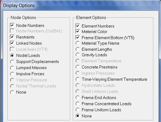
21 Frame Element Bottom 21

22 5. PERFORMING AN ANALYSIS Once the structure and loading have been created, you can perform a VecTor5 analysis. For this, you need to save the input text files created by FormWorks Plus into the folder which contains VT5.exe program. To save the individual files, click on the following save icons. The red icon saves the Job file, the blue icon saves the Structure file, and the green icon saves the Load file. Now that the files have been saved, the VecTor5 analysis program can be activated using the following icon. This icon is located adjacent to the save icons discussed above. Alternatively, the analysis may be initiated by going into the folder and double clicking on VT5.exe file. Upon clicking on the VT icon, the following screen appears, showing that the processor VecTor5 is performing the calculations and creating an output file for each load stage. These files are readily available for review in the folder where all files are saved, which is shown below. These files can be opened and viewed using Notepad or other text editors. Expanded data (.S5E) and expanded load files (.L5E) are particularly important to check for the input and modeling mistakes. They list all input in a tabular format for visual inspection. Material properties calculated by VecTor5 should also be checked for accuracy using the.s5e file. For example, check the Ec and e0 values to ensure that they match the values that you wish to use. For more information about the VecTor5 processor and the files it produces, please refer to the User s Manual of VecTor5. 22

23 5.1 Retrieving Output Data To access the data files that VecTor5 has created, go to the folder where it has saved the files shown above. To obtain the load-deflection data, it is necessary to copy the VT5Data_X.exe or VT5Data_Y.exe programs into this folder. This folder is also where the Job, Structure, and Load files are saved by the FWP program. Once the data program is copied, open the file to generate the following window. In this window, enter the information as the program prompts. For this example, the reaction node is 1, and the nodal displacement is applied at node 7. In a displacement controlled analysis with a single displacement applied, the same node number should be input for both the reaction and the displacement. This is due to the fact that VecTor5 calculates the reaction for the applied displacement at this node. Once the information is entered, click Enter to allow the program to read the output data files one by one. Once completed, a text file named results.dat will be generated in the same folder. Open this file to view a tabulated list of the load versus deflection data for the beam, respectively. Copy and paste this information into Excel or a graphing program to create charts and graphs to display the data. The Results data file for a beam is shown below, where the nodal displacement is in the left column and the reaction is in the right column. 23
, was obtained from the journal paper of Vecchio and Shim (2004). 5.")


24 For this beam, the following graph can be created for the Load versus Deflection data obtained. The load is at node 1, the deflection is at node 7. The experimental data for this beam (VS-A1), was obtained from the journal paper of Vecchio and Shim (2004). 5.2 Troubleshooting There may be times when the VecTor5 processor displays an error message and will not perform the analysis. In most cases, the black DOS screen will pause and show the error message. If this window closes before displaying the error message, you need to initialize the VT5.exe using the command prompt. For Windows operating systems, right click on the start menu and select Command Prompt. Type CD xxx, where xxx is the full file path of the folder containing all analysis files. You can copy (Ctrl + C) and paste (Ctrl + V) this path from the title bar of Windows File Explorer. Then, type VT5.exe into the DOS window. This will initialize the program and show the error message. 24

25 Errors for to the stiffness matrix, such as being not positive definitive, is commonly related to the support conditions. Check the model to ensure that at least three restrains are specified for the structure. Another common error is the definition of only one load stage in the Job file. In this case, the analysis will terminate after this load stage. Please use more load stages to resolve this problem. 5.3 Visualizing the Analysis Results To view the results from the VecTor5 analysis, you can use the Janus post-processor, which reads the output text files one by one and displays the results in a graphical manner. First, open the Job file using the top menu of Janus. You will see the VT5 View Options menu shown below, which will provide options. You can adjust the view options or change the load stages using the + and icons. You can also set a particular load stage. The example below shows load stage 12. The crack locations and crack widths can be seen; white lines represent minor cracks of less than 0.1 mm; black is up to 0.1 mm width; bold black up to 1 mm width; and red lines are for cracks larger than 2 mm. For the reinforcement, green is first yielding, yellow is strain hardening, and red lines is for rupture. Refer to the User s Manual of Janus and watch-and-learn videos. 25


26 6. TOOLBAR MENUS An alternate method of creating the structure is using the menus on the top of the screen as discussed below. 6.1 File The first menu is File. This menu allows the user to create a New structure or Open an existing one. Also, the user can Close, Save, Save As, or Print the structure which is currently being created. In this menu, the user can also Exit the program. 6.2 Edit This menu is currently inactive. 6.3 View The next tab is the View menu, shown below. The user can set the Limits of the display, as shown below. There are also options to Zoom to show the entire structure, a specific window, as well as zoom in and zoom out. There are options to Pan across the screen, and Display Options. 26

27 6.4 Job Next to the View menu is the Job menu. Here, the user can open the Define Job dialog, and Save the Job File. The Job menu is used to create the VecTor.JOB file. 6.5 Structure The next option is the Structure menu. The user can view the Structure Information, Define the Materials, Define and Mesh the structure, create nodes and elements, as well as view the Structure Limits. It is recommended that you use the auto-meshing feature discussed above rather than using this menu. 6.6 Load The following menu refers to the Load information. In this menu, the user can activate the Load cases, Apply Nodal Loads, Apply Element Loads, Ground Acceleration, Clear the Load Case, Save the Load Case File (.L5R), as well as view the Load Limits of the structure. 27


28 6.7 Analysis The next menu is for the Analysis. In this menu, the user can Run the VecTor Processor and the Janus post-processor. With the Janus postprocessor, the user can view the reactions and failures of the output members. This is a very useful program, which is discussed in its entirety in the Users Manual for Janus. 6.8 Window Next is the Window menu. In this menu, the user can create a New Window, Cascade and Tile the windows, as well as Arrange the Icons. This is useful for keeping your work organized. 28
29 6.9 Help The final menu in the toolbar is the Help menu. Here, the user can view which version of FormWorks Plus is being used to create the structure. The program for this manual is Version Toolbar Icons Below the toolbar, there are icons for accessing the premier features of the toolbar menus. The buttons, respectively, are New, Open, Save the Workspace, Print, Zoom All, Zoom In, Zoom Out, Zoom Window, Display Options, Increase Text Size, and Decrease Text Size. It is very important to frequently save the workspace file while creating the structure to avoid losing your work. 7. CONCLUSION This manual allows the FormWorks Plus user to become familiar with the use the program to prepare text files for an analysis with VecTor5. Using FormWorks Plus to prepare the text files will allow VecTor5 analyses to be performed on structures of any complexity. To better understand the VecTor5 program and the process behind the FormWorks Plus graphical interface, it is highly recommended to read the User s Manual of VecTor5 and the User s Manual of Janus for VecTor5, both of which can be downloaded here. Watch and Learn videos can be found here. These videos show how to use the programs to model various structures. 29
Start AxisVM by double-clicking the AxisVM icon in the AxisVM folder, found on the Desktop, or in the Start, Programs Menu.
 1. BEAM MODEL Start New Start AxisVM by double-clicking the AxisVM icon in the AxisVM folder, found on the Desktop, or in the Start, Programs Menu. Create a new model with the New Icon. In the dialogue
Tutorial 1: Welded Frame - Problem Description
 Tutorial 1: Welded Frame - Problem Description Introduction In this first tutorial, we will analyse a simple frame: firstly as a welded frame, and secondly as a pin jointed truss. In each case, we will
Idealization of Design Strip in ADAPT RC
 ADAPT RC 2010 Tutorial Idealization of Design Strip in ADAPT RC Update: May 2010 Copyright ADAPT Corporation all rights reserved ADAPT RC 2010 Tutorial 1 Main Toolbar Menu Bar View Toolbar Structure View
Frame Analysis Using Visual Analysis
 Frame Analysis Using Visual Analysis 1. The software is available at the Open Access Labs (OAL) and the Virtual OAL at http://voal.tamu.edu in Programs under the Windows Start menu. The software can also
Reinforced concrete beam under static load: simulation of an experimental test
 Reinforced concrete beam under static load: simulation of an experimental test analys: nonlin physic. constr: suppor. elemen: bar cl12i cl3cm compos cq16m interf pstres reinfo struct. load: deform weight.
Step by Step. Tutorial for AxisVM X4. Edited by: Inter-CAD Kft.
 Step by Step Tutorial for AxisVM X4 Edited by: Inter-CAD Kft. 2018 Inter-CAD Kft. All rights reserved All brand and product names are trademarks or registered trademarks. Intentionally blank page Step
The Generate toolbar has convenient tools to create typical structural shapes.
 Frame Analysis Using Multiframe 1. The software is on the computers in the College of Architecture in Programs under the Windows Start menu (see https://wikis.arch.tamu.edu/display/helpdesk/computer+accounts
ADAPT-PT/RC 2018 Getting Started Tutorial ADAPT-RC mode
 ADAPT-PT/RC 2018 Getting Started Tutorial ADAPT-RC mode Update: September 2018 Copyright ADAPT Corporation all rights reserved ADAPT-PT/RC 2017-Tutorial- 1 This ADAPT-PT/RC 2018 Getting Started Tutorial
Advance Design. Tutorial
 TUTORIAL 2018 Advance Design Tutorial Table of Contents About this tutorial... 1 How to use this guide... 3 Lesson 1: Preparing and organizing your model... 4 Step 1: Start Advance Design... 5 Step 2:
ADAPT-PT/RC 2014 Getting Started Tutorial ADAPT-RC mode
 ADAPT-PT/RC 2014 Getting Started Tutorial ADAPT-RC mode Update: January 2014 Copyright ADAPT Corporation all rights reserved ADAPT-PT/RC 2014-Tutorial- 1 This ADAPT-PT/RC 2014 Getting Started Tutorial
CME-TRUSS (Version 2.1) User's Manual
 User's Manual") CME-TRUSS (Version 2.1) User's Manual INTRODUCTION CME-TRUSS is an interactive program for structural analysis of two-dimensional trusses. The software is written in the Microsoft Visual Basic for Windows
CME-TRUSS (Version 2.1) User's Manual INTRODUCTION CME-TRUSS is an interactive program for structural analysis of two-dimensional trusses. The software is written in the Microsoft Visual Basic for Windows
Module 1.6: Distributed Loading of a 2D Cantilever Beam
 Module 1.6: Distributed Loading of a 2D Cantilever Beam Table of Contents Page Number Problem Description 2 Theory 2 Geometry 4 Preprocessor 7 Element Type 7 Real Constants and Material Properties 8 Meshing
Beams. Lesson Objectives:
 Beams Lesson Objectives: 1) Derive the member local stiffness values for two-dimensional beam members. 2) Assemble the local stiffness matrix into global coordinates. 3) Assemble the structural stiffness
RSPile. Tutorial 3 Grouped Pile Analysis. Pile Analysis Software. Grouped Pile Analysis
 RSPile Pile Analysis Software Tutorial 3 Grouped Pile Analysis Grouped Pile Analysis Introduction This tutorial will demonstrate how to model grouped piles under a cap. The finished product of this tutorial
Module 1.5: Moment Loading of a 2D Cantilever Beam
 Module 1.5: Moment Loading of a D Cantilever Beam Table of Contents Page Number Problem Description Theory Geometry 4 Preprocessor 7 Element Type 7 Real Constants and Material Properties 8 Meshing 9 Loads
PLAXIS 2D - SUBMERGED CONSTRUCTION OF AN EXCAVATION
 PLAXIS 2D - SUBMERGED CONSTRUCTION OF AN EXCAVATION 3 SUBMERGED CONSTRUCTION OF AN EXCAVATION This tutorial illustrates the use of PLAXIS for the analysis of submerged construction of an excavation. Most
1. Define the material properties. Activate the Data Entry menu if it s not already visible, and click on Materials.
 CE 533, Fall 2014 Guide for Using RISA3D 1 / 9 Example Structure. The procedure for calculating frequencies and modes shapes of a multidegree of freedom (MDOF) system will be demonstrated using the following
Learning Module 8 Shape Optimization
 Learning Module 8 Shape Optimization What is a Learning Module? Title Page Guide A Learning Module (LM) is a structured, concise, and self-sufficient learning resource. An LM provides the learner with
Frame Analysis Using Multiframe4D
 Frame Analysis Using Multiframe4D 1. The software is on the computers in the college computing lab (http://thelab.tamu.edu) in Programs under the Windows Start menu. Multiframe4D is under the COSC menu.
SUBMERGED CONSTRUCTION OF AN EXCAVATION
 2 SUBMERGED CONSTRUCTION OF AN EXCAVATION This tutorial illustrates the use of PLAXIS for the analysis of submerged construction of an excavation. Most of the program features that were used in Tutorial
SAFI Sample Projects. Design of a Steel Structure. SAFI Quality Software Inc. 3393, chemin Sainte-Foy Ste-Foy, Quebec, G1X 1S7 Canada
 SAFI Sample Projects Design of a Steel Structure SAFI Quality Software Inc. 3393, chemin Sainte-Foy Ste-Foy, Quebec, G1X 1S7 Canada Contact: Rachik Elmaraghy, P.Eng., M.A.Sc. Tel.: 1-418-654-9454 1-800-810-9454
Important Note - Please Read:
 Important Note - Please Read: This tutorial requires version 6.01 or later of SAFE to run successfully. You can determine what version of SAFE you have by starting the program and then clicking the Help
Column - solid section
 1 Column - solid section This example demonstrates how how to design a column with an arbitrary cross-section defined by the user. The model is a simple one member column, loaded with an axial load and
Problem O. Isolated Building - Nonlinear Time History Analysis. Steel E =29000 ksi, Poissons Ratio = 0.3 Beams: W24X55; Columns: W14X90
 Problem O Isolated Building - Nonlinear Time History Analysis Steel E =29000 ksi, Poissons Ratio = 0.3 Beams: W24X55; Columns: W14X90 Rubber Isolator Properties Vertical (axial) stiffness = 10,000 k/in
Module 1.7: Point Loading of a 3D Cantilever Beam
 Module 1.7: Point Loading of a D Cantilever Beam Table of Contents Page Number Problem Description Theory Geometry 4 Preprocessor 6 Element Type 6 Material Properties 7 Meshing 8 Loads 9 Solution 15 General
Oasys GSA. Getting Started
 Getting Started 13 Fitzroy Street London W1T 4BQ Telephone: +44 (0) 20 7755 3302 Facsimile: +44 (0) 20 7755 3720 Central Square Forth Street Newcastle Upon Tyne NE1 3PL Telephone: +44 (0) 191 238 7559
E and. L q. AE q L AE L. q L
 STRUTURL NLYSIS [SK 43] EXERISES Q. (a) Using basic concepts, members towrds local axes is, E and q L, prove that the equilibrium equation for truss f f E L E L E L q E q L With f and q are both force
Tekla Structures Analysis Guide. Product version 21.0 March Tekla Corporation
 Tekla Structures Analysis Guide Product version 21.0 March 2015 2015 Tekla Corporation Contents 1 Getting started with analysis... 7 1.1 What is an analysis model... 7 Analysis model objects...9 1.2 About
FB-MULTIPIER vs ADINA VALIDATION MODELING
 FB-MULTIPIER vs ADINA VALIDATION MODELING 1. INTRODUCTION 1.1 Purpose of FB-MultiPier Validation testing Performing validation of structural analysis software delineates the capabilities and limitations
ME 475 FEA of a Composite Panel
 ME 475 FEA of a Composite Panel Objectives: To determine the deflection and stress state of a composite panel subjected to asymmetric loading. Introduction: Composite laminates are composed of thin layers
Start AxisVM by double-clicking the AxisVM icon in the AxisVM folder, found on the Desktop, or in the Start, Programs Menu.
 4. MEMBRANE MODEL 1.1. Preprocessing with surface elements Start New Start AxisVM by double-clicking the AxisVM icon in the AxisVM folder, found on the Desktop, or in the Start, Programs Menu. Create a
Version October 2015 RFEM 5. Spatial Models Calculated acc. to Finite Element Method. Introductory Example
 Version October 2015 Program RFEM 5 Spatial Models Calculated acc. to Finite Element Method Introductory Example All rights, including those of translations, are reserved. No portion of this book may be
ANALYSIS OF BOX CULVERT - COST OPTIMIZATION FOR DIFFERENT ASPECT RATIOS OF CELL
 ANALYSIS OF BOX CULVERT - COST OPTIMIZATION FOR DIFFERENT ASPECT RATIOS OF CELL M.G. Kalyanshetti 1, S.A. Gosavi 2 1 Assistant professor, Civil Engineering Department, Walchand Institute of Technology,
SETTLEMENT OF A CIRCULAR FOOTING ON SAND
 1 SETTLEMENT OF A CIRCULAR FOOTING ON SAND In this chapter a first application is considered, namely the settlement of a circular foundation footing on sand. This is the first step in becoming familiar
SECTION ANALYSIS PROGRAM RESPONSE 2000
 SECTION ANALYSIS PROGRAM RESPONSE 2000 DESCRIPTION Response-2000 is a user friendly sectional analysis program that can be used to predict the complete load-deformation response of a reinforced or prestressed
Revised Sheet Metal Simulation, J.E. Akin, Rice University
 Revised Sheet Metal Simulation, J.E. Akin, Rice University A SolidWorks simulation tutorial is just intended to illustrate where to find various icons that you would need in a real engineering analysis.
ANALYSIS OF COMPOSITE CONCRETE SLAB ON METAL DECK
 ANALYSIS OF COMPOSITE CONCRETE SLAB ON METAL DECK Assignment #5 Select a Vulcraft composite deck to support 150 psf service live load on a 10 ft clear span. The steel deck is to be used on a three-span
Use of S-Frame and S-Steel
 Problem #2: Step by Step modeling, analysis and design: 1 o Create a new 2D model starting from scratch: 2 o The following GEOMETRY window will be opened: o Right click on the joint tool in the shortcuts
Ansys Lab Frame Analysis
 Ansys Lab Frame Analysis Analyze the highway overpass frame shown in Figure. The main horizontal beam is W24x162 (area = 47.7 in 2, moment of inertia = 5170 in 4, height = 25 in). The inclined members
Module 1.2: Moment of a 1D Cantilever Beam
 Module 1.: Moment of a 1D Cantilever Beam Table of Contents Page Number Problem Description Theory Geometry Preprocessor 6 Element Type 6 Real Constants and Material Properties 7 Meshing 9 Loads 10 Solution
FOUNDATION IN OVERCONSOLIDATED CLAY
 1 FOUNDATION IN OVERCONSOLIDATED CLAY In this chapter a first application of PLAXIS 3D is considered, namely the settlement of a foundation in clay. This is the first step in becoming familiar with the
2: Static analysis of a plate
 2: Static analysis of a plate Topics covered Project description Using SolidWorks Simulation interface Linear static analysis with solid elements Finding reaction forces Controlling discretization errors
Two Dimensional Truss
 Two Dimensional Truss Introduction This tutorial was created using ANSYS 7.0 to solve a simple 2D Truss problem. This is the first of four introductory ANSYS tutorials. Problem Description Determine the
CE Advanced Structural Analysis. Lab 1 Introduction to SAP2000
 Department of Civil & Geological Engineering COLLEGE OF ENGINEERING CE 463.3 Advanced Structural Analysis Lab 1 Introduction to SAP2000 January 09 th, 2013 T.A: Ouafi Saha Professor: M. Boulfiza Objectives:
Truss Analysis using Multiframe
 Truss Analysis using Multiframe 1. The software is on the teaching computers in the College of Architecture in Programs under the Windows Start menu. Multiframe is under the Bentley Engineering menu. It
Lab Practical - Finite Element Stress & Deformation Analysis
 Lab Practical - Finite Element Stress & Deformation Analysis Part A The Basics In this example, some of the basic features of a finite element analysis will be demonstrated through the modelling of a simple
CE Advanced Structural Analysis. Lab 4 SAP2000 Plane Elasticity
 Department of Civil & Geological Engineering COLLEGE OF ENGINEERING CE 463.3 Advanced Structural Analysis Lab 4 SAP2000 Plane Elasticity February 27 th, 2013 T.A: Ouafi Saha Professor: M. Boulfiza 1. Rectangular
Guide to WB Annotations
 Guide to WB Annotations 04 May 2016 Annotations are a powerful new feature added to Workbench v1.2.0 (Released May 2016) for placing text and symbols within wb_view tabs and windows. They enable generation
SDC. Engineering Analysis with COSMOSWorks. Paul M. Kurowski Ph.D., P.Eng. SolidWorks 2003 / COSMOSWorks 2003
 Engineering Analysis with COSMOSWorks SolidWorks 2003 / COSMOSWorks 2003 Paul M. Kurowski Ph.D., P.Eng. SDC PUBLICATIONS Design Generator, Inc. Schroff Development Corporation www.schroff.com www.schroff-europe.com
To complete this activity, you will need the following files:
 CHAPTER 1 Windows XP More Skills 12 Move Data Between Windows You can open several application windows at the same time; they do not need to be files created by the same program. Having more than one window
TABLE OF CONTENTS INTRODUCTION...2
 WINGARD PE 6.0 August 2010 TABLE OF CONTENTS TABLE OF CONTENTS...1 1. INTRODUCTION...2 2. PROGRAM OVERVIEW...3 2.1. PROGRAM MENUS... 4 2.2. MAIN TOOLBAR... 5 2.3. ANALYSIS... 7 2.4. OUTPUT... 10 2.5. DISPLAY
TrussMaster: Educational Truss Analysis Software Version 3 User Manual Dublin Institute of Technology, Ireland
 TrussMaster: Educational Truss Analysis Software Version 3 User Manual Dublin Institute of Technology, Ireland 1 Acknowledgements This program has been developed over 10 years from 2001 by Dr Colin Caprani.
ME Week 12 Piston Mechanical Event Simulation
 Introduction to Mechanical Event Simulation The purpose of this introduction to Mechanical Event Simulation (MES) project is to explorer the dynamic simulation environment of Autodesk Simulation. This
WinIGS. Windows Based Integrated Grounding System Design Program. Structural Dynamic Analysis Training Guide. Last Revision: February 2017
 WinIGS Windows Based Integrated Grounding System Design Program Structural Dynamic Analysis Training Guide Last Revision: February 2017 Copyright A. P. Sakis Meliopoulos 2009-2017 NOTICES Copyright Notice
3. Check by Eurocode 3 a Steel Truss
 TF 3. Check by Eurocode 3 a Steel Truss Applicable CivilFEM Product: All CivilFEM Products Level of Difficulty: Moderate Interactive Time Required: 40 minutes Discipline: Structural Steel Analysis Type:
Important Note - Please Read:
 Important Note - Please Read: This tutorial requires version 6.01 or later of SAFE to run successfully. You can determine what version of SAFE you have by starting the program and then clicking the Help
CE366/ME380 Finite Elements in Applied Mechanics I Fall 2007
 CE366/ME380 Finite Elements in Applied Mechanics I Fall 2007 FE Project 1: 2D Plane Stress Analysis of acantilever Beam (Due date =TBD) Figure 1 shows a cantilever beam that is subjected to a concentrated
Probabilistic Analysis Tutorial
 Probabilistic Analysis Tutorial 2-1 Probabilistic Analysis Tutorial This tutorial will familiarize the user with the Probabilistic Analysis features of Swedge. In a Probabilistic Analysis, you can define
SAP 2000 Problem II Homework Problem P5.45. Recall from Lab #6 the Global and Local Reference Coordinate Systems for 2D Problems
 SAP 2000 Problem II Homework Problem P5.45 Recall from Lab #6 the Global and Local Reference Coordinate Systems for 2D Problems Z 2 Global (XYZ) Coordinate System Joint Displacements Applied Point Loads
Revit Structure 3 ETABS Data Exchange
 Revit Structure 3 ETABS Data Exchange Overview This document describes how to exchange Building Information Modeling (BIM) data between Revit Structure 3 and ETABS, a three-dimensional physical object
CSiBridge 2015 (Version ) Release Notes
 Release Notes") CSiBridge 2015 (Version 17.3.0) Release Notes Copyright Computers and Structures, Inc., 2015 Notice Date: 2015-07-02 This file lists all changes made to CSiBridge since the previous version. Most changes
CSiBridge 2015 (Version 17.3.0) Release Notes Copyright Computers and Structures, Inc., 2015 Notice Date: 2015-07-02 This file lists all changes made to CSiBridge since the previous version. Most changes
ADAPT MAT RC Tutorial (SI units with European Code EC2) Update: April 2010 Copyright ADAPT Corporation all rights reserved
 Update: April 2010 Copyright ADAPT Corporation all rights reserved") ADAPT MAT RC Tutorial (SI units with European Code EC2) Update: April 2010 Copyright ADAPT Corporation all rights reserved ADAPT MAT RC Tutorial (SI units with European Code EC2) I TABLE OF CONTENTS 1
ADAPT MAT RC Tutorial (SI units with European Code EC2) Update: April 2010 Copyright ADAPT Corporation all rights reserved ADAPT MAT RC Tutorial (SI units with European Code EC2) I TABLE OF CONTENTS 1
Bonded Block Modeling of a Tunnel Excavation with Support
 Bonded Block Modeling of a Tunnel Excavation with Support 1 Modeling Procedure Step 1 Step 2 Step 3 Step 4 Step 5 Step 6 Generate the blocks to define the tunnel geometry Assign properties to blocks and
SAFE DESIGN OF SLABS, BEAMS AND FOUNDATIONS REINFORCED AND POST-TENSIONED CONCRETE. Tutorial
 Tutorial SAFE DESIGN OF SLABS, BEAMS AND FOUNDATIONS REINFORCED AND POST-TENSIONED CONCRETE Tutorial ISO SAF112816M3 Rev. 0 Proudly developed in the United States of America November 2016 Copyright Copyright
Investigation of the behaviour of single span reinforced concrete historic bridges by using the finite element method
 Structural Studies, Repairs and Maintenance of Heritage Architecture XI 279 Investigation of the behaviour of single span reinforced concrete historic bridges by using the finite element method S. B. Yuksel
D DAVID PUBLISHING. Stability Analysis of Tubular Steel Shores. 1. Introduction
 Journal of Civil Engineering and Architecture 1 (216) 563-567 doi: 1.17265/1934-7359/216.5.5 D DAVID PUBLISHING Fábio André Frutuoso Lopes, Fernando Artur Nogueira Silva, Romilde Almeida de Oliveira and
Example: 3D structural model of a building frame with pinned connections
 SAFIR training session level 1 Johns Hopkins University, Baltimore Example: 3D structural model of a building frame with pinned connections 3D building frame with concrete columns and steel beams T. Gernay
Manual for Computational Exercises
 Manual for the computational exercise in TMM4160 Fracture Mechanics Page 1 of 32 TMM4160 Fracture Mechanics Manual for Computational Exercises Version 3.0 Zhiliang Zhang Dept. of Structural Engineering
Quick & Simple Imaging. User Guide
 Quick & Simple Imaging User Guide The Quick & Simple Imaging software package provides the user with a quick and simple way to search and find their documents, then view, print, add notes, or even e- mail
Tutorial. External Application Checks using Excel
 Tutorial External Application Checks using Excel External Application Checks for Excel All information in this document is subject to modification without prior notice. No part or this manual may be reproduced,
Appendix B: Creating and Analyzing a Simple Model in Abaqus/CAE
 Getting Started with Abaqus: Interactive Edition Appendix B: Creating and Analyzing a Simple Model in Abaqus/CAE The following section is a basic tutorial for the experienced Abaqus user. It leads you
Analysis Steps 1. Start Abaqus and choose to create a new model database
 Source: Online tutorials for ABAQUS Problem Description The two dimensional bridge structure, which consists of steel T sections (b=0.25, h=0.25, I=0.125, t f =t w =0.05), is simply supported at its lower
Simulation of fiber reinforced composites using NX 8.5 under the example of a 3- point-bending beam
 R Simulation of fiber reinforced composites using NX 8.5 under the example of a 3- point-bending beam Ralph Kussmaul Zurich, 08-October-2015 IMES-ST/2015-10-08 Simulation of fiber reinforced composites
NonLinear Materials AH-ALBERTA Web:
 NonLinear Materials Introduction This tutorial was completed using ANSYS 7.0 The purpose of the tutorial is to describe how to include material nonlinearities in an ANSYS model. For instance, the case
LESM. Linear Elements Structure Model. Version 1.0 August Luiz Fernando Martha
 LESM Linear Elements Structure Model Version 1.0 August 2017 http://www.tecgraf.puc-rio.br/lesm by Luiz Fernando Martha (lfm@tecgraf.puc-rio.br) Rafael Lopez Rangel (rafaelrangel@tecgraf.puc-rio.br) Pontifical
CE371 Structural Analysis II Lecture 5:
 CE371 Structural Analysis II Lecture 5: 15.1 15.4 15.1) Preliminary Remarks 15.2) Beam-Member Stiffness Matrix 15.3) Beam-Structure Stiffness Matrix 15.4) Application of the Stiffness Matrix. 15.1) Preliminary
Program and Graphical User Interface Design
 CHAPTER 2 Program and Graphical User Interface Design OBJECTIVES You will have mastered the material in this chapter when you can: Open and close Visual Studio 2010 Create a Visual Basic 2010 Windows Application
TABLE OF CONTENTS WHAT IS ADVANCE DESIGN? INSTALLING ADVANCE DESIGN... 8 System requirements... 8 Advance Design installation...
 Starting Guide 2019 TABLE OF CONTENTS INTRODUCTION... 5 Welcome to Advance Design... 5 About this guide... 6 Where to find information?... 6 Contacting technical support... 6 WHAT IS ADVANCE DESIGN?...
Pro MECHANICA STRUCTURE WILDFIRE 4. ELEMENTS AND APPLICATIONS Part I. Yves Gagnon, M.A.Sc. Finite Element Analyst & Structural Consultant SDC
 Pro MECHANICA STRUCTURE WILDFIRE 4 ELEMENTS AND APPLICATIONS Part I Yves Gagnon, M.A.Sc. Finite Element Analyst & Structural Consultant SDC PUBLICATIONS Schroff Development Corporation www.schroff.com
Modeling Skills Stress Analysis J.E. Akin, Rice University, Mech 417
 Introduction Modeling Skills Stress Analysis J.E. Akin, Rice University, Mech 417 Most finite element analysis tasks involve utilizing commercial software, for which you do not have the source code. Thus,
System Components for Precast Concrete Tekla Structures 12.0 Basic Training September 19, 2006
 System Components for Precast Concrete Tekla Structures 12.0 Basic Training September 19, 2006 Copyright 2006 Tekla Corporation Copyright 2006 Tekla Corporation SYSTEM COMPONENTS FOR PRECAST CONCRETE ii
TSTOWER FOR SELF-SUPPORTING LATTICED TOWERS
 TSTOWER FOR SELF-SUPPORTING LATTICED TOWERS STRUCTURAL ANALYSIS SOFTWARE FOR COMMUNICATION TOWERS USER S MANUAL BY JOHN WAHBA, PH.D., P.ENG., P.E. MATTHEW MALINOWSKI, P.ENG. WWW.TOWERSFT.COM TABLE OF CONTENTS
Multiframe Windows Version 16. User Manual
 Multiframe Windows Version 16 User Manual Bentley Systems, Incorporated 2013 License & Copyright Multiframe Program & User Manual 2013 Bentley Systems, Incorporated iii Table of Contents License & Copyright...
Label Printing Software BA-300 Version 1.00
 Label Printing Software BA-300 Version 1.00 EN For Windows User s Guide What you can do with the BA-300 Application Using the BA-300 Application Troubleshooting Be sure to keep all user documentation handy
2D Tutorial. Project Description: Running VisualAnalysis: Setting Up the Project:
 2D Tutorial Project Description: This project has been set-up to demonstrate the basic features of VisualAnalysis. You will model and analyze the following two-dimensional frame with a curved glue-laminated
================================== spcolumn v Upgraded November 2018 ==================================
 spcolumn v6.50 - Upgraded November 2018 1. Introduced new sp2d/3dview module with the following features, for viewing and navigating 2D diagrams and 3D surfaces (a) Advanced and flexible graphical interface
5. Shell Reinforcement According To Eurocode 2
 5. Shell Reinforcement According To Eurocode Applicable CivilFEM Product: All CivilFEM Products Level of Difficulty: Moderate Interactive Time Required: 5 minutes Discipline: Concrete Shell Reinforcement
STRUCTURAL CONCRETE SOFTWARE ADAPT-ABI 2009 GETTING STARTED GUIDE. Copyright 2009
 STRUCTURAL CONCRETE SOFTWARE ADAPT-ABI 2009 GETTING STARTED GUIDE Copyright 2009 Copyright ADAPT Corporation 2009 all rights reserved support@adaptsoft.com www.adaptsoft.com ADAPT Corporation, Redwood
CONCRETE DESIGN SOFTWARE LIBRARY
 CONCRETE DESIGN SOFTWARE LIBRARY DESIGN AND INVESTIGATION OF REINFORCED CONCRETE CONTINUOUS BEAMS PORTLAND CEMENT ASSOCIATION 5420 Old Orchard Road, Skokie, Illinois 60077-1083 Telephone: (847) 966-4357
Qualification of *Constrained_Lagrange_In_Solid command for steel/concrete interface modeling
 Qualification of *Constrained_Lagrange_In_Solid command for steel/concrete interface modeling L. MOUTOUSSAMY 1,2, G. HERVE 1, F. BARBIER 1 1 Tractebel Engineering France, 2 University Pierre and Marie
Multiframe May 2010 Release Note
 Multiframe 12.02 18 May 2010 Release Note This release note describes the version 12.02 release of Multiframe, Steel Designer and Section Maker. This release will run on Windows XP/2003/Vista/7. Contents
ATENA Program Documentation Part 4-2. Tutorial for Program ATENA 3D. Written by: Jan Červenka, Zdenka Procházková, Tereza Sajdlová
 Červenka Consulting s.ro. Na Hrebenkach 55 150 00 Prague Czech Republic Phone: +420 220 610 018 E-mail: cervenka@cervenka.cz Web: http://www.cervenka.cz ATENA Program Documentation Part 4-2 Tutorial for
TS Series Tensile Machines. Impact Test Equipment Ltd
 TS Series Tensile Machines Impact Test Equipment Ltd www.impact-test.co.uk - www.impact-test.com www.impact-testsets.co.uk www.impact-test.com www.impact-test.co.uk www.impact-testsets.co.uk www.impact-test.com
Tutorial for MASTAN2 version 3.0
 Tutorial for version 3.0 Developed by: Ronald D. Ziemian Professor of Civil Engineering Bucknell University William McGuire Professor of Civil Engineering, Emeritus Cornell University JOHN WILEY & SONS,
THREE DIMENSIONAL ACES MODELS FOR BRIDGES
 THREE DIMENSIONAL ACES MODELS FOR BRIDGES Noel Wenham, Design Engineer, Wyche Consulting Joe Wyche, Director, Wyche Consulting SYNOPSIS Plane grillage models are widely used for the design of bridges,
A block is pushed onto a rigid cylinder as shown:
 Problem description Problem 43: Contact between a block and a rigid cylinder, TLA-S method A block is pushed onto a rigid cylinder as shown: Prescribed force = 10 5 N 0.1 All lengths in meters 0.01 0.1
Case Study - Vierendeel Frame Part of Chapter 12 from: MacLeod I A (2005) Modern Structural Analysis, ICE Publishing
 Modern Structural Analysis, ICE Publishing") Case Study - Vierendeel Frame Part of Chapter 1 from: MacLeod I A (005) Modern Structural Analysis, ICE Publishing Iain A MacLeod Contents Contents... 1 1.1 Vierendeel frame... 1 1.1.1 General... 1 1.1.
Case Study - Vierendeel Frame Part of Chapter 1 from: MacLeod I A (005) Modern Structural Analysis, ICE Publishing Iain A MacLeod Contents Contents... 1 1.1 Vierendeel frame... 1 1.1.1 General... 1 1.1.
16 SW Simulation design resources
 16 SW Simulation design resources 16.1 Introduction This is simply a restatement of the SW Simulation online design scenarios tutorial with a little more visual detail supplied on the various menu picks
CE2302 STRUCTURAL ANALYSIS I Important Questions PART B
 CE2302 STRUCTURAL ANALYSIS I Important Questions PART B UNIT I 1. Determine the vertical and horizontal displacement of the joint B in a pin jointed frame shown in fig. 2. The cross sectional area of each
ANSYS AIM Tutorial Thermal Stresses in a Bar
 ANSYS AIM Tutorial Thermal Stresses in a Bar Author(s): Sebastian Vecchi, ANSYS Created using ANSYS AIM 18.1 Problem Specification Pre-Analysis & Start Up Pre-Analysis Start-Up Geometry Draw Geometry Create