STRUCTURAL CONCRETE SOFTWARE ADAPT-ABI 2009 GETTING STARTED GUIDE. Copyright 2009
|
|
|
- Gwendolyn Cobb
- 5 years ago
- Views:
Transcription
 306-2400 ADAPT International Pvt. Ltd.")
1 STRUCTURAL CONCRETE SOFTWARE ADAPT-ABI 2009 GETTING STARTED GUIDE Copyright 2009 Copyright ADAPT Corporation 2009 all rights reserved ADAPT Corporation, Redwood City, CA, USA, Tel: +1 (650) ADAPT International Pvt. Ltd., Kolkata, India, Tel:
2 LIST OF CONTENTS 1 ADAPT-ABI 2009 USER INTERFACE TUTORIAL 1: MODELING OF SINGLE SPAN BRIDGE WITH MOVING LOAD IN DIFFERENT STAGES GENERATE THE MODEL DEFINE THE LOADING DEFINE CONSTRUCTION STAGES ANALYZE THE STRUCTURE REVIEW THE RESULTS GRAPHICALLY Bending Moment SAVING THE MODEL AS ABI v4 FILE TUTORIAL 2: MODELING OF FOUR SPAN BRIDGE WITH THREE MOVING LOAD PATHS AND BULB-T SECTION GENERATE THE MODEL MESH AND DEFINE CONSTRUCTION STAGES DEFINE TRAVEL PATHS WITH SECTORS DEFINE MOVING LOAD CASES DEFINE LOAD COMBINATIONS AND ENVELOPES ANALYZE THE STRUCTURE REVIEW THE RESULTS GRAPHICALLY TUTORIAL 3: IMPORTING AN ABI v4 INPUT FILE
3 Getting Started Thank you for choosing ADAPT-ABI This Getting Started Guide is intended to provide you with a brief overview of the capabilities of the ADAPT-ABI 2009 product. In following the tutorials below, you will learn how to model a structure and perform the necessary design steps. For more details about the program please refer to the ADAPT-ABI user manuals. 3

4 1 ADAPT-ABI 2009 USER INTERFACE Toolbars Menu Bar Modeling Space Command Line Project Browser Status Bar 4
5 2 TUTORIAL 1: MODELING OF SINGLE SPAN BRIDGE WITH MOVING LOAD IN DIFFERENT STAGES The objective of this tutorial is to model a single span bridge girder with moving load. The cross section used is a single cell box girder with 1 m depth and 5 m width (Fig. 2-1). FIGURE 2-1 Span Section Single cell box girder cross section of 5000 mm width and 1000 mm depth. Pier Section Loadings Moving Loads Material Properties Support Tendon Analysis Rectangular cross section of 1000 mm width. Point load of 4 kn will be applied at a distance of 10 meters from left end. 1. ABI_MIXED 2. ABI_TRUCK 1. Concrete: default ACI concrete model 2. Mild Steel: default material properties Fixed supports are used at the both ends. 200 KN stressing at both ends. Execute ABI and view analysis results graphically and in text format 5

6 2.1 GENERATE THE MODEL To model and analyze a segmental bridge in ABI 2009 follow the following steps: 1. Go to Start menu in Windows, select ADAPT-Builder ABI 2009 under ADAPT Application program group. 2. Program will display ADAPT-ABI Configuration dialog box as shown in Figure FIGURE Select SI unit and click OK. ABI 2009 will appear on the screen. 4. At this point, if required, please go to the User Interface menu (Fig ) and turn on any or all required toolbar(s) for your operation. However, for beginners this step is not recommended. 6

7 FIGURE On the Snap Toolbar click on the Grid Setting tool and the program will display the dialog box on your screen as shown in Figure

8 FIGURE Let us specify 5 m for both Horizontal Spacing and Z spacing. Now click OK. 7. Then click on Snap to Grid on the Snap toolbar to view the grid lines and create points only at the intersections of the grid lines. 8. Then click on Display WCS on the Setting toolbar to view the WCS on your screen. 9. Click on Create a Reference Line icon on the Model toolbar (Fig ). FIGURE Enter first point and last point at a distance of 40 m in X direction, then Press C from the keyboard. Program will display the reference line on the screen as shown in Figure
9 FIGURE Go to Development View on the Camera and View ports toolbar (Fig ). FIGURE Click on Create/Identify a segment on the Model toolbar. 13. Enter a first point and last point at a distance of 20 m on the reference line, then Press C on keyboard. ABI 2009 will display one segment on your screen as shown in Figure FIGURE Click on Define Section on the Model toolbar. The program will display the Section Manager on your screen same as shown in Figure

10 FIGURE In Section Manager go to Properties and select Single cell girder. Put Bf = 5000 mm, B = 2000 mm, t = 300 mm, Hf = 300 mm, H= 1000 mm, a = 600 mm. Then click on the green check mark. Again go to Properties and select Rectangular. Put width b = 1000mm, height h = 1000 mm and click on Add. Then press OK to save sections in section manager. 16. Double click on the segment and the program will display the dialog box named Segment on your screen as shown in Figure In that box go to Section tab, select Section 1 for Starting Cross Section and Ending Cross Section. Then click on the green check mark and exit the property box. 10

11 FIGURE Click on Create/Identify a Column or Pier on the Model toolbar. 18. Enter most left end and most right end of the segment respectively to create two columns of 5 m height. 19. Double click on the 1 st column and the program will display the dialog box named Pier/Column on your screen, same as shown in Figure In the Section Tab, select Section 2 for both Starting Cross Section and Ending Cross Sections respectively. Then click on the green check mark and exit. Follow the same steps for 2 nd column as well. 11


12 FIGURE Click Concrete under the Material menu bar. Program will display the dialog box as shown below. Select ACI 1978 on the Concrete Model tab (Fig ). FIGURE

13 21. Click on Create a Point Support on the Model toolbar and enter the point position of support by clicking on the end points of each column. It is best to turn off the grid and to select the Snap to Endpoint option instead. 22. Double click on 1 st support and the program will display the property box Point Support as shown in Figure On the General tab select Fixed under Degree freedom and then click on the green check mark and exit. Follow the same steps for 2 nd point support as well. FIGURE Click on the Create a Tendon menu under the Model toolbar. Enter the Left End and Right End points of segment respectively and Press C on your keyboard. Program will display the tendon in the structure as shown in Figure

14 FIGURE DEFINE THE LOADING 24. Click Load Case Library (Fig ) under the Loading menu bar. The Program will display the dialog box as shown below. Click the Add button. Highlight Load_Case_1 and insert DL into the Label filed. Then click OK. FIGURE Click on Create Point Load on the Load toolbar. Enter the point at which to apply the point load at a distance of 10 meter from left end. FIGURE Double Click on the point load and the program will display the property box named Point Load as shown below. On the General tab put the value Fz = KN and change the load case name as DL (Fig ). Click on the green check mark and exit. 14

15 FIGURE Click on Add Selfweight on the Load toolbar. Put the value Gz = (Fig ). Press OK. FIGURE Go to the Travel Path option under Moving Load menu. Select the left end of the span as the 1 st point and the right end of the span as the 2 nd point of the travel path. This way you create a travel path along the entire span. 29. Go to the Moving Load Library option under Moving Load menu. Observe all the moving load trains that are available in the existing library. You will be using ABI_MIXED and ABI_TRUCK in the following step. 30. Go to the Load Case option on the Moving Load menu and the program will display the dialog box named Moving Load Cases on your screen, same as shown in Figure Select ABI_MIXED under Load trains. Select Travel_Path_1 in the Travel paths box. Click on Both under Factors and travel directions. Click the ADD button in the 15
16 Combination List. Click the ADD button in Moving load cases to create the load case called Case1. FIGURE To create a 2 nd load case, first create Case2 by clicking on Add under Moving load cases. Then highlight Case2, select ABI_TRUCK under Load trains, select Travel_Path_1 under Travel paths box, and then click on Both under Factors and travel directions. Click the ADD button in Combinations list. The program will display both load cases in the list named Moving Load Cases on your screen same as shown in Figure
17 FIGURE Click Load Combinations / Envelopes in the Loading menu. Set the factors for DL and Case1 to 1 and click on Create Load Combination. Set the factors for DL and Case2 to 1 and click on Save As Load Combination. Next, set the factors for Case1 and Case2 to 1 and click on Save As Load Combination. The program will display all three load combinations in the dialog box as shown in Figure Then click OK. The "Base_load" load case includes all loads applied to the structure in the construction phase, excluding prestressing and long term effects. The Current load case includes all loads applied to the structure in the construction phase, including prestressing and long term effects. 17

18 FIGURE


19 2.3 DEFINE CONSTRUCTION STAGES 33. Click Create Mesh in the Process menu. The program will display the dialog box as shown in Figure Insert a value of 2 m for Suggested cell size. Then click OK. FIGURE In the Project Browser, create the following days: 1, 10, 20 and 30. Simply enter 1 into the Day field and hit Add. This creates a Day: 1 in the Project Browser s tree structure including a Step_1. Notice that Step_1 is editable once created since in most cases you would want to rename the steps. Create days 10, 20, and 30 accordingly. If the Project Browser is not visible, click on Project Browser in the View menu. Check the Output All checkmark to receive output for every step in the Result Viewer. FIGURE
20 35. Select Step_1, right-click on it and select Rename. Rename this step to Install supports and piers. 36. In the same way, rename Step_2 to Install span, Step_3 to Stress tendon and Step_4 to Apply load. The Project Browser will then appear as shown in Figure Select both supports and piers, right-click and select Install at step. Use Ctrl key on your keyboard to select multiple structures at a time. 38. Select Install span in the Project Browser. Select all span segments, then right click on your mouse and select Install at step. You will notice that the selected segments are now drawn with a thicker line. 39. Select Stress tendon in the Project Browser. Double-click on the tendon to open its property box and select the Stressing tab. Ensure that in the Stressing history Day 20 is highlighted, then select Jack Ratio from the drop down list on the bottom and set the value to 0.80 (Fig ). Confirm by clicking on the green checkmark and close the property box. 40. You can now view the construction sequence in greater detail and adjust with the help of the Event Manager. Go to Event in the Build menu to open the Event Manager. In the left list box you will find the days and steps you created. The list box on the far right is a pre-compiled list of all the events that you specified so far. For example, on day 1 you specified that the supports be installed as well as the piers (note that the piers consist of segments and hence, segments are installed). The Solve command at the beginning of each day moves the solution over the time interval from the period at the end of the previous solution to the day number specified. 20

21 41. On day 10, you also want to apply the selfweight of the segment. To add this to the Event Manager, you select Day 10, select from the middle list box Apply Selfweight which is part of the Loading tree, and then click on the arrow that points to the right between the middle and the very right list box. Notice in the right list box that the command Apply Selfweight is now the last command on day 10. Highlight this command and click the Move up button once to move it between Install Restraint and Solve as shown in Figure If you wish to see the results (e.g., moments, stresses) in the result viewer for a specific day, you can simply add the Output command at the end of each day. Therefore, select any day in the very left list box, then select the Output command from the middle list box that lists all possible operations and click on the arrow that points to the right between the middle and the very right list box. This will add the Output command as the last command for the selected day in the right list box. For this example, ensure that you have one Output command at the end of each day. Your Event Manager will then look like shown in Figure FIGURE

22 FIGURE ANALYZE THE STRUCTURE 43. Select Generate Input Data in the Process menu. 44. Select Generate Input Data for Moving Load in the Process menu. 45. Select Execute in the Process menu. 46. Select Execute Moving Load in the Process menu. 22

23 2.5 REVIEW THE RESULTS GRAPHICALLY 47. Click on View Results in the Process menu to open the result viewer Bending Moment. 48. Click on Bending Moment in the Action and Stresses toolbar. Program will display the bending moment diagram as shown in Figure for Stage 4 which you can select either from the drop down box or you can walk through the stages with the help of the vertical blue arrows. FIGURE You can view the bending moment for a load combination. Go to CC in the Right Side Post Construction Combo Box (Fig ) and observe the moment diagram (Fig ). In the same manner, you can display shear forces, axial forces, pre-stressing forces, stresses, and torsion moments. Simply select the desired option from the Action and Stresses toolbar. FIGURE
24 FIGURE
25 2.6 SAVING THE MODEL AS ABI v4 FILE In ABI 2009 you have the option to save your model as a v4 input file and analyze it. This enables you to compare your results. 50. With your.abi model opened in ABI 2009, you simply select Save as v4 INP in the File menu. This opens the Save As window where you can specify the name and the location of the input file. 51. Once you have saved the v4 input file, ABI transforms the abi model into a v4 input file. If there is a moving load file related to the input file, the moving load file stays the same and gets saved in the same location that you defined in step 50. Also, the ABI interface turns off all modeling-related options that are not needed for a v4 file. You can now validate and run this model or open up a different model. 52. Select Execute in the Process menu. 53. Select Execute Moving Load in the Process menu. 54. Click on View Results in the Process menu to open the result viewer. 55. If you now choose to view the bending moment for Stage 4, you receive the same answer as with your 2009 model and which is displayed in Figure
26 3 TUTORIAL 2: MODELING OF FOUR SPAN BRIDGE WITH THREE MOVING LOAD PATHS AND BULB-T SECTION This tutorial requires that you have successfully completed tutorial 1. The objective of this tutorial is to model a four span bridge and three load paths with different load patterns. The cross section used is a Bulb-T with 50 inches depth and 36 inches width (Fig. 3-1). FIGURE 3-1 Span Section Pier Section Bulb-T cross section of 50 inches depth and 36 inches width. Rectangular cross section 36 x 24 inches. Moving Loads 1) HS20_14: HS-20 truck with 14 ft distance between axle 2 and 3 2) HS20_16: HS-20 truck with 16 ft distance between axle 2 and 3 3) HS20_18: HS-20 truck with 18 ft distance between axle 2 and 3 4) HS20_20: HS-20 truck with 20 ft distance between axle 2 and 3 5) HS20_22: HS-20 truck with 22 ft distance between axle 2 and 3 6) HS20_24: HS-20 truck with 24 ft distance between axle 2 and 3 7) HS20_26: HS-20 truck with 26 ft distance between axle 2 and 3 8) HS20_28: HS-20 truck with 28 ft distance between axle 2 and 3 9) HS20_30: HS-20 truck with 30 ft distance between axle 2 and 3 10) MILTRK: Military truck with axle distance of 4 ft and 24 kips of concentrated load Material Properties Support Analysis Concrete: default ACI concrete model Mild Steel: default material properties Fixed supports are used at all ends. Execute ABI and Moving Load 26

27 3.1 GENERATE THE MODEL 1. Open ABI 2009 and select the American unit system in the ADAPT-ABI Configuration window. 2. On the Camera and Viewports Toolbar, click on Front View. 3. On the Snap Toolbar, click on Grid Settings and define 10 ft for both, Horizontal spacing and Vertical spacing. Then click on Snap to Grid, which is located on the same toolbar. 4. Ensure that your Model Toolbar is visible, click on Create a Reference Line and draw a horizontal reference line that is 200 ft long. 5. In the Section Manager, you define the cross sections needed for this model. Click on the Define Sections button on the Model Toolbar to open the Section Manager. 6. The default shape is Rectangular. Enter 36 inches for the width and 24 inches for the height and click the green checkmark to propagate the dimension changes. Doubleclick on the Label field of your Rectangular cross section, change the label to 36x24 and hit Enter on your keyboard. Keep your Section Manager open. 7. Next, you define your BulbT cross section. Click on the Add button to add one more line in your cross section list. Select BulbT-Section from the drop down list and change the dimension for H1 to 50 inches. Confirm the change with the green check mark. Double-click on the Label field of your BulbT cross section, change the label to BulbT-50 and hit Enter on your keyboard. You have now successfully created a rectangular and a BulbT cross section (Fig ). You can close the Section Manager by clicking on OK. FIGURE
28 8. To model the structure, you have to be in the Developed View. Therefore, click on the Developed View button on the Camera and Viewports Toolbar. 9. First, you will create the four spans. On the Snap Toolbar, click on Snap to Endpoint. Click on the Create a Segment button on the Model Toolbar and snap to the left endpoint of the reference line and then to the right endpoint of the reference line. Make a right-click and select Exit from the menu. You now have a segment that is 200 feet long. 10. Now you need to ensure that spans have the correct cross section. Double-click on the segment and its property box opens (Fig ). Go to the Section tab and select BulbT-50 from the Section I and the Section J drop down list. Confirm with the green check mark and close the property box. The cross section of your four spans is the BulbT-50 that you defined earlier in the Section Manager. FIGURE Next, you will create the five piers with equal distances of 50 feet. Ensure that none of the snapping options on the Snap Toolbar are chosen. Click the Create Column / Pier button on the Model Toolbar and click on the left end of the reference line which is also the left end of your girder. Open the property box of the pier, go to the Section tab and select 36x24 for Section I and Section J. Confirm with the green check mark and close the property box. You have now created the first out of five piers beneath your girder. Click 50 feet (5 cells on the grid) right next to the left beginning of the girder to place the second pier and create three more piers in the same manner. After all the piers are created, make a right click and select Exit from the menu. 28
29 12. The piers are 10 feet tall by default. To make them taller, you can click on the Grid Settings button on the Snap Toolbar and change the Horizontal and Vertical spacing to 5 feet. Then click OK and you will see that the grid cell size changes to 5 x 5 ft. Now drag the lower ends of your piers one by one to the next lower grid vertex. 13. You need to model the point supports on the bottom of the piers. Click on Create a point support button on the Model Toolbar and click on center point of the lower end of each pier to create a point support at those locations. Once the fifth point support is created, make a right click and select Exit from the menu. 14. The point supports are by default modeled as hinged point supports. You want to change them to fixed point supports. Therefore, click on the Select by Type button on the Selection Toolbar. This opens the Select by Type window. Select Point Support from the list and click OK. This highlights all five point supports that you have modeled. Now select Modify Item Properties from the Modify menu which opens the Modify Item Properties window. Then select the Point Support tab, check the checkbox on that tab and select Fixed in the Degree freedom group frame. Confirm with OK. If you open any point support property box you will notice on the General tab that the boundary condition is now changed to Fixed. 3.2 MESH AND DEFINE CONSTRUCTION STAGES 15. Click Create Mesh in the Process menu. The program will display the dialog box as shown in Figure Insert a value of 3 ft. for Suggested cell size. Then click OK. 16. You may want to define some construction stages according to what is described in Chapter 2.3. Or you can simply select Day 0 in the Project browser, select the entire structure in the modeling space then right click on your mouse and select Install at step. This will install the entire structure theoretically in one day. 29

30 3.3 DEFINE TRAVEL PATHS WITH SECTORS 17. In the next step, you will model the first out of three travel paths consisting of four sectors over each span. Go to the Moving Load menu and select Travel Path. Click on the grid vertex at the left start of your girder where also your reference line starts to define the start point of your travel path. Move along the reference line and click on the grid vertex that is on the reference line above the second pier. Keep moving along the reference line and click on the grid vertices above the third, fourth and fifth pier. After you have clicked above the fifth pier, hit C and then Esc on your keyboard to finish the operation. You have now successfully created the first travel path that consists of four sectors, one sector over each span. 18. Double click on the travel path to open its property box, put PATHALL into the Label field, confirm with the green check mark and close the property box. 19. Create a second and third travel path in the same manner. 20. Double click on the second travel path to open its property box and you will see that the four sectors are listed on the General tab in the Skipping option group frame. For this travel path, you want to skip the even sectors, therefore click on the Skip even sectors button. Put ODD_SPNS into the Label field, confirm with the green check mark and close the property box. 21. For the third travel path, you want to skip the odd sectors. Double click on the third travel path to open its property box and click on the Skip odd sectors button. Put EVN_SPNS into the Label field, confirm with the green check mark and close the property box. 3.4 DEFINE MOVING LOAD CASES 22. Open the Moving Load Library through the Moving Load menu (Fig ) and you will notice that the required HS20 trucks are already specified in the AASHTO load train library. The only truck that you need to define is the Military (MILTRK) load train. FIGURE

31 23. Click on one of the HS20 trucks and click on the Add button on the bottom of the page to add a new load train. In the Load train name field, enter MILTRK as the name. 24. The load train has two axles which are modeled as two concentrated loads of 24 kips each and a distance of 4 feet between the two axles. Select Concentrated from the drop down box under Type and type -24 into the F field. Then increase the Number of load components to two which will give you two concentrated loads of 24 kips. Since the distance is defined as the space between the last and the current load, you have to put 4 into the Distance field of the second concentrated load. 25. Click OK to confirm and to close the Moving Load Library. 26. You need to associate the individual load trains to load paths. Open the Load Case in the Moving Load menu to open the Moving Load Cases window. Select C_SHR in the Load trains group frame and select PATHALL in the Travel paths group frame. Leave the values for Factor and Distribution as 1.00, ensure that the Max for sign check box is not selected and select Forward. Click on Add above the Load trains group frame to generate the combination. Click on Add below the Moving load cases group frame to create a case. This case will be labeled automatically Case1, you can go to the Label field and rename it to SHEAR (Fig shows all moving load cases that have to be created). FIGURE To generate the next moving load case, click on Add below the Moving load cases group frame, rename it to LN_ALL, select the load train UNI_ALL and the travel path PATHALL, check the check box for Max for sign and click on ADD above the Load trains group frame. 31
32 28. In the same manner, create the following moving load cases settings provided in Table The factor and distribution factors are always set to Load case Load train Travel path Direction Max for sign LN_ODD UNI_ALL ODD_SPNS Forward Unchecked LN_EVN UNI_ALL EVN_SPNS Forward Unchecked POS_M C_POSM PATHALL Forward Unchecked NEG_MO C_NEGM ODD_SPNS Forward Unchecked NEG_ME C_NEGM EVN_SPNS Forward Unchecked HS_14 HS20_14 PATHALL Forward Checked HS_16 HS20_16 PATHALL Forward Checked HS_18 HS20_18 PATHALL Forward Checked HS_20 HS20_20 PATHALL Forward Checked HS_22 HS20_22 PATHALL Forward Checked HS_24 HS20_24 PATHALL Forward Checked HS_26 HS20_26 PATHALL Forward Checked HS_28 HS20_28 PATHALL Forward Checked HS_30 HS20_30 PATHALL Forward Checked MILTRK MILTRK PATHALL Forward Checked 29. Confirm with OK to close the Moving Load Cases window. 32
33 3.5 DEFINE LOAD COMBINATIONS AND ENVELOPES 30. Go to the Loading menu and click on Load Combinations / Envelopes to open the Load Combinations / Envelopes window. In the Create and edit combinations/envelopes group frame you find a list of all load cases, load combinations and envelopes. Enter 1.00 as the Factor for the load cases NEG_MO and NEG_ME and click on the Create Load Combination button. You will notice that a load combination was created in the Combinations list. Highlight the name and rename the combination to C_NEGM and hit Enter on your keyboard. 31. In the same manner, create the following load combinations: Name Combination SHR 1.00 * SHEAR * LN_ENV LN_NEG 1.00 * C_NEGM * LN_ENV LN_POS 1.00 * LN_EVN * POS_M 32. You will want to create five envelopes in this window as well. In the top list, highlight LN_ALL, LN_ODD, and LN_EVN using your Ctrl button on your keyboard. Click the Create Envelope button to create the first envelope. Highlight its name and rename it to LN_ENV and hit Enter on your keyboard. 33. In the same manner, create the following envelopes: Name Envelope HS20EN HS_14, HS_16, HS_18, HS_20, HS_22, HS_24, HS_26, HS_28, HS_30 MAX_M MAX_V LANE MIL_M MIL_V LANE, HS20EN SHR, HS20EN LN_NEG, LN_POS MAX_M, MILTRK MAX_V, MILTRK 34. Click on OK to confirm and to close the Load Combination / Envelope window. 33

34 3.6 ANALYZE THE STRUCTURE 35. Select Generate Input Data in the Process menu. 36. Select Generate Input Data for Moving Load in the Process menu. 37. Select Execute in the Process menu. 38. Select Execute Moving Load in the Process menu. 3.7 REVIEW THE RESULTS GRAPHICALLY 39. Select View Results in the Process menu and activate the post-construction drop down box by clicking on the yellow arrow pointing to the right. 40. Select Max_M and click on the Bending Moment button to review your moment envelope (Fig ). FIGURE Select Max_V and click on the Shear button to review your shear envelope (Fig ). FIGURE
. FIGURE 3-1 2. Go to the File menu and select the submenu item Generic ADAPT File in the Import submenu.")
35 4 TUTORIAL 3: IMPORTING AN ABI v4 INPUT FILE This tutorial shows you how to import an input file that follows the ADAPT-ABI version 4.xx syntax into ABI Start ABI 2009 and select any unit in the ADAPT-ABI Configuration window (Fig. 3-1). FIGURE Go to the File menu and select the submenu item Generic ADAPT File in the Import submenu. This allows you to import input files that follow the ADAPT-ABI v4 syntax. 3. In the Open window (Fig. 3-2), browse to the location of the input file, select it and hit Open. For this tutorial, we use SAMPLE.INP which is one of the examples that come with ABI v4.5. In case a moving load file is related to the input file you import (i.e., a moving load file with the same file name exists in the folder your input file is located), this moving load file is automatically imported. In our case, SAMPLE.INP does have a SAMPLE.MOV related to it and which will get imported as well. FIGURE

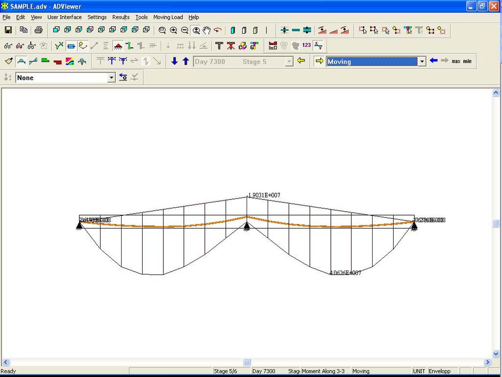
36 4. Once the import of your file(s) was successful, a confirmation message appears, which confirms the files and includes the file paths that were imported (Fig. 3-3). Click on OK. FIGURE The ABI interface turns off all modeling-related options that are not needed for a v4 file. You can now validate and run this model or open up a different model. 6. Select Execute in the Process menu. 7. Select Execute Moving Load in the Process menu. 8. Click on View Results in the Process menu to open the result viewer. 9. Click on Bending Moment in the Action and Stresses toolbar. Program will display the bending moment diagram as shown in Figure 3-4. for Stage 5, which you can select either from the drop down box or you can walk through with the help of the vertical blue arrows. If you compare the results with ABI v4.5 you will notice that you will receive exactly the same answer. FIGURE You can view the bending moment for a load combination or load case. Go to Moving in the Right Side Post Construction Combo Box (Fig. 3.-5) and observe the moment diagram (Fig. 3.-6). 36

37 FIGURE 3-5 FIGURE
STRUCTURAL CONCRETE SOFTWARE SYSTEM ADAPT-ABI 2012 USER MANUAL. Copyright 2012
 STRUCTURAL CONCRETE SOFTWARE SYSTEM ADAPT-ABI 2012 USER MANUAL Copyright 2012 support@adaptsoft.com www.adaptsoft.com ADAPT Corporation, Redwood City, California, USA, Tel: +1 (650) 306-2400 Fax: +1 (650)
STRUCTURAL CONCRETE SOFTWARE SYSTEM ADAPT-ABI 2009 USER MANUAL. Copyright 2009
 STRUCTURAL CONCRETE SOFTWARE SYSTEM ADAPT-ABI 2009 USER MANUAL Copyright 2009 support@adaptsoft.com www.adaptsoft.com ADAPT Corporation, Redwood City, California, USA, Tel: +1 (650) 306-2400 Fax: +1 (650)
Important Note - Please Read:
 Important Note - Please Read: This tutorial requires version 6.01 or later of SAFE to run successfully. You can determine what version of SAFE you have by starting the program and then clicking the Help
Important Note - Please Read:
 Important Note - Please Read: This tutorial requires version 6.01 or later of SAFE to run successfully. You can determine what version of SAFE you have by starting the program and then clicking the Help
STRUCTURAL CONCRETE SOFTWARE SYSTEM ADAPT-MODELER 2010 USER MANUAL. Copyright 2010
 MNL 403 STRUCTURAL CONCRETE SOFTWARE SYSTEM ADAPT-MODELER 2010 USER MANUAL Copyright 2010 support@adaptsoft.com www.adaptsoft.com ADAPT Corporation, Redwood City, California, USA, Tel: +1 (650) 306-2400
Technical Issues. Frequently Asked Questions Frequently Encountered Errors. - Featuring - ADAPT-ABI 2009
 Technical Issues Frequently Asked Questions Frequently Encountered Errors - Featuring - ADAPT-ABI 2009 ADAPT Corporation, USA ADAPT International Pvt. Ltd, Kolkata, India Tuesday, November 17, 2009 1 What
Advance Design. Tutorial
 TUTORIAL 2018 Advance Design Tutorial Table of Contents About this tutorial... 1 How to use this guide... 3 Lesson 1: Preparing and organizing your model... 4 Step 1: Start Advance Design... 5 Step 2:
Idealization of Design Strip in ADAPT RC
 ADAPT RC 2010 Tutorial Idealization of Design Strip in ADAPT RC Update: May 2010 Copyright ADAPT Corporation all rights reserved ADAPT RC 2010 Tutorial 1 Main Toolbar Menu Bar View Toolbar Structure View
Bridge Design using the STAAD.Pro/Beava AASHTO Code
 Bridge Design using the STAAD.Pro/Beava AASHTO Code By IEG Group, Bentley Systems Bentley Systems Inc. March 12, 2008 TABLE OF CONTENTS 1.0 Introduction.1 2.0 Creating the Bridge Geometry/Structural Analysis
Problem O. Isolated Building - Nonlinear Time History Analysis. Steel E =29000 ksi, Poissons Ratio = 0.3 Beams: W24X55; Columns: W14X90
 Problem O Isolated Building - Nonlinear Time History Analysis Steel E =29000 ksi, Poissons Ratio = 0.3 Beams: W24X55; Columns: W14X90 Rubber Isolator Properties Vertical (axial) stiffness = 10,000 k/in
TUTORIAL INCLUDING PUSHOVER ANALYSIS
 SAP2000 Integrated Finite Elements Analysis and Design of Structures DETAILED TUTORIAL INCLUDING PUSHOVER ANALYSIS Computers and Structures, Inc. Berkeley, California, USA Version 6.20 Beta June 1998 COPYRIGHT
ADAPT-PT/RC 2014 Getting Started Tutorial ADAPT-RC mode
 ADAPT-PT/RC 2014 Getting Started Tutorial ADAPT-RC mode Update: January 2014 Copyright ADAPT Corporation all rights reserved ADAPT-PT/RC 2014-Tutorial- 1 This ADAPT-PT/RC 2014 Getting Started Tutorial
3ds Max Cottage Step 1. Always start out by setting up units: We re going with this setup as we will round everything off to one inch.
 3ds Max Cottage Step 1 Always start out by setting up units: We re going with this setup as we will round everything off to one inch. File/Import the CAD drawing Be sure Files of Type is set to all formats
ADAPT-INTEGRATION CONSOLE
 STRUCTURAL CONCRETE SOFTWARE SYSTEM ADAPT-INTEGRATION CONSOLE Version 2009 USER MANUAL Copyright 2009 support@adaptsoft.com www.adaptsoft.com ADAPT Corporation, Redwood City, California, USA, Tel: +1 (650)
ADAPT-PT/RC 2018 Getting Started Tutorial ADAPT-RC mode
 ADAPT-PT/RC 2018 Getting Started Tutorial ADAPT-RC mode Update: September 2018 Copyright ADAPT Corporation all rights reserved ADAPT-PT/RC 2017-Tutorial- 1 This ADAPT-PT/RC 2018 Getting Started Tutorial
Frame Analysis Using Multiframe4D
 Frame Analysis Using Multiframe4D 1. The software is on the computers in the college computing lab (http://thelab.tamu.edu) in Programs under the Windows Start menu. Multiframe4D is under the COSC menu.
Tekla Structures Analysis Guide. Product version 21.0 March Tekla Corporation
 Tekla Structures Analysis Guide Product version 21.0 March 2015 2015 Tekla Corporation Contents 1 Getting started with analysis... 7 1.1 What is an analysis model... 7 Analysis model objects...9 1.2 About
ADAPT MAT RC Tutorial (SI units with European Code EC2) Update: April 2010 Copyright ADAPT Corporation all rights reserved
 Update: April 2010 Copyright ADAPT Corporation all rights reserved") ADAPT MAT RC Tutorial (SI units with European Code EC2) Update: April 2010 Copyright ADAPT Corporation all rights reserved ADAPT MAT RC Tutorial (SI units with European Code EC2) I TABLE OF CONTENTS 1
ADAPT MAT RC Tutorial (SI units with European Code EC2) Update: April 2010 Copyright ADAPT Corporation all rights reserved ADAPT MAT RC Tutorial (SI units with European Code EC2) I TABLE OF CONTENTS 1
The Generate toolbar has convenient tools to create typical structural shapes.
 Frame Analysis Using Multiframe 1. The software is on the computers in the College of Architecture in Programs under the Windows Start menu (see https://wikis.arch.tamu.edu/display/helpdesk/computer+accounts
SAFI Sample Projects. Design of a Steel Structure. SAFI Quality Software Inc. 3393, chemin Sainte-Foy Ste-Foy, Quebec, G1X 1S7 Canada
 SAFI Sample Projects Design of a Steel Structure SAFI Quality Software Inc. 3393, chemin Sainte-Foy Ste-Foy, Quebec, G1X 1S7 Canada Contact: Rachik Elmaraghy, P.Eng., M.A.Sc. Tel.: 1-418-654-9454 1-800-810-9454
Pre-Lab Excel Problem
 Pre-Lab Excel Problem Read and follow the instructions carefully! Below you are given a problem which you are to solve using Excel. If you have not used the Excel spreadsheet a limited tutorial is given
2D Tutorial. Project Description: Running VisualAnalysis: Setting Up the Project:
 2D Tutorial Project Description: This project has been set-up to demonstrate the basic features of VisualAnalysis. You will model and analyze the following two-dimensional frame with a curved glue-laminated
AASHTOWare BrR - SIMPLE SPAN PRESTRESSED I BEAM EXAMPLE - BR 76015
 AASHTOWare BrR - SIMPLE SPAN PRESTRESSED I BEAM EXAMPLE - BR 76015 M N D O T B R I D G E S T A T E A I D Page 1 PS1 - Simple Span Prestressed I Beam Example (BrR 6.7.1) 1. From the Bridge Explorer create
Start AxisVM by double-clicking the AxisVM icon in the AxisVM folder, found on the Desktop, or in the Start, Programs Menu.
 1. BEAM MODEL Start New Start AxisVM by double-clicking the AxisVM icon in the AxisVM folder, found on the Desktop, or in the Start, Programs Menu. Create a new model with the New Icon. In the dialogue
Tutorial 4 Arch Bridge
 Tutorial 4 Arch Bridge Civil TUTORIAL 4. ARCH BRIDGE Summary 1 Analysis Model and Load Cases / 2 File Opening and Preferences Setting 5 Enter Material and Section Properties 6 Structural Modeling Using
AASHTOWare BrD/BrR 6.8 Reinforced Concrete Structure Tutorial RC6 Two Span Reinforced Concrete Slab System Example
 AASHTOWare BrD/BrR 6.8 Reinforced Concrete Structure Tutorial RC6 Two Span Reinforced Concrete Slab System Example AASHTOWare Bridge Design and Rating Training 6" A A 30'-0" 30'-0" B #11's #11's 1'-6"
SAFE DESIGN OF SLABS, BEAMS AND FOUNDATIONS REINFORCED AND POST-TENSIONED CONCRETE. Tutorial
 Tutorial SAFE DESIGN OF SLABS, BEAMS AND FOUNDATIONS REINFORCED AND POST-TENSIONED CONCRETE Tutorial ISO SAF112816M3 Rev. 0 Proudly developed in the United States of America November 2016 Copyright Copyright
A02 - How to Combine Existing Model with New DWG
 Objective: The purpose of this tutorial is to explain how to combine an existing model with a new DWG. This is often required when there is any change or amendmend in the architechtural drawing or plan
v Data Visualization SMS 12.3 Tutorial Prerequisites Requirements Time Objectives Learn how to import, manipulate, and view solution data.
 v. 12.3 SMS 12.3 Tutorial Objectives Learn how to import, manipulate, and view solution data. Prerequisites None Requirements GIS Module Map Module Time 30 60 minutes Page 1 of 16 Aquaveo 2017 1 Introduction...
ekaizen Lessons Table of Contents 1. ebook Basics 1 2. Create a new ebook Make Changes to the ebook Populate the ebook 41
 Table of Contents 1. ebook Basics 1 2. Create a new ebook 20 3. Make Changes to the ebook 31 4. Populate the ebook 41 5. Share the ebook 63 ekaizen 1 2 1 1 3 4 2 2 5 The ebook is a tabbed electronic book
ADAPT-Builder. Toolbar Descriptions Updated November Copyright All rights reserved 2017
 ADAPT-Builder Toolbar Descriptions Updated November 2017 Copyright All rights reserved 2017 Main Toolbar The Main Toolbar is where the typical functions that are in most programs such as New, Open, Save,
LARSA Section Composer. for. LARSA 2000 Finite Element Analysis and Design Software
 for LARSA 2000 Finite Element Analysis and Design Software Larsa, Inc. Melville, New York, USA Revised August 2004 Table of Contents Features 4 Sections & Shapes 5 Using Section Composer 7 Creating Shapes
Frame Analysis Using Visual Analysis
 Frame Analysis Using Visual Analysis 1. The software is available at the Open Access Labs (OAL) and the Virtual OAL at http://voal.tamu.edu in Programs under the Windows Start menu. The software can also
XnView Image Viewer. a ZOOMERS guide
 XnView Image Viewer a ZOOMERS guide Introduction...2 Browser Mode... 5 Image View Mode...14 Printing... 22 Image Editing...26 Configuration... 34 Note that this guide is for XnView version 1.8. The current
Basic Modeling 1 Tekla Structures 12.0 Basic Training September 19, 2006
 Tekla Structures 12.0 Basic Training September 19, 2006 Copyright 2006 Tekla Corporation Contents Contents 3 1 5 1.1 Start Tekla Structures 6 1.2 Create a New Model BasicModel1 7 1.3 Create Grids 10 1.4
Tutorial For LamTopo
 Tutorial For LamTopo Automatic Grid Generation for LaModel One of the nicest features introduced in LaModel 2.0 was the capability of building the seam and topographic grid automatically from AutoCAD files.
FINITE ELEMENT ANALYSIS OF A PLANAR TRUSS
 Problem Description: FINITE ELEMENT ANALYSIS OF A PLANAR TRUSS Instructor: Professor James Sherwood Revised: Dimitri Soteropoulos Programs Utilized: Abaqus/CAE 6.11-2 This tutorial explains how to build
Learning Module 8 Shape Optimization
 Learning Module 8 Shape Optimization What is a Learning Module? Title Page Guide A Learning Module (LM) is a structured, concise, and self-sufficient learning resource. An LM provides the learner with
Quick Crash Scene Tutorial
 Quick Crash Scene Tutorial With Crash Zone or Crime Zone, even new users can create a quick crash scene diagram in less than 10 minutes! In this tutorial we ll show how to use Crash Zone s unique features
EXAMPLE 1. Static Analysis of Cantilever Column (Fixed-Base Column)
") EXAMPLE 1 Static Analysis of Cantilever Column (Fixed-Base Column) Calculate the top displacement, axial force, shear force and bending moment diagrams for the fixed base column described in the figure
EXAMPLE 1 Static Analysis of Cantilever Column (Fixed-Base Column) Calculate the top displacement, axial force, shear force and bending moment diagrams for the fixed base column described in the figure
ES 230 Strengths Intro to Finite Element Modeling & Analysis Homework Assignment 2
 ES 230 Strengths Intro to Finite Element Modeling & Analysis Homework Assignment 2 In this homework assignment you will use your rapidly developing ANSYS skill set to model and analyze three different
Tutorial 01 Quick Start Tutorial
 Tutorial 01 Quick Start Tutorial Homogeneous single material slope No water pressure (dry) Circular slip surface search (Grid Search) Intro to multi scenario modeling Introduction Model This quick start
Colony Counting User Manual A D I V I S I O N O F S Y N O P T I C S L T D
 ProtoCOL Colony Counting User Manual S Y N B I O S I S A D I V I S I O N O F S Y N O P T I C S L T D All possible care has been taken in the preparation of this publication, but Synoptics Limited accepts
Lesson 1: Creating T- Spline Forms. In Samples section of your Data Panel, browse to: Fusion 101 Training > 03 Sculpt > 03_Sculpting_Introduction.
 3.1: Sculpting Sculpting in Fusion 360 allows for the intuitive freeform creation of organic solid bodies and surfaces by leveraging the T- Splines technology. In the Sculpt Workspace, you can rapidly
Appendix B: Creating and Analyzing a Simple Model in Abaqus/CAE
 Getting Started with Abaqus: Interactive Edition Appendix B: Creating and Analyzing a Simple Model in Abaqus/CAE The following section is a basic tutorial for the experienced Abaqus user. It leads you
POS Designer Utility
 POS Designer Utility POS Designer Utility 01/15/2015 User Reference Manual Copyright 2012-2015 by Celerant Technology Corp. All rights reserved worldwide. This manual, as well as the software described
Randy H. Shih. Jack Zecher PUBLICATIONS
 Randy H. Shih Jack Zecher PUBLICATIONS WWW.SDCACAD.COM AutoCAD LT 2000 MultiMedia Tutorial 1-1 Lesson 1 Geometric Construction Basics! " # 1-2 AutoCAD LT 2000 MultiMedia Tutorial Introduction Learning
WinAqua TUTORIAL WinAqua
 WinAqua TUTORIAL WinAqua WinAqua TUTORIAL Copyright SOFiSTiK AG, D-81514 Műnchen, 1990-2002 This documentation is protected by copyright. No part of it may be reproduced, translated or rewritten in any
Layout Tutorial. Getting Started. Creating a Layout Template
 Layout Tutorial This tutorial will explain how create a layout template, send views to a layout page, then save the document in PDF format. In this tutorial you will learn about: Creating a Layout Template
Word 3 Microsoft Word 2013
 Word 3 Microsoft Word 2013 Mercer County Library System Brian M. Hughes, County Executive Action Technique 1. Insert a Text Box 1. Click the Insert tab on the Ribbon. 2. Then click on Text Box in the Text
Layout Tutorial. Getting Started. Creating a Layout Template
 Layout Tutorial This tutorial will explain how create a layout template, send views to a layout page, then save the document in PDF format. In this tutorial you will learn about: Creating a Layout Template
v SMS 12.2 Tutorial Observation Prerequisites Requirements Time minutes
 v. 12.2 SMS 12.2 Tutorial Observation Objectives This tutorial will give an overview of using the observation coverage in SMS. Observation points will be created to measure the numerical analysis with
Boat Hull Solid. (Alt-2). in ribbon bar to fix and close ribbon Fig. 3 Mastercam X7 BOAT HULL SOLID Page 29-1
. in ribbon bar to fix and close ribbon Fig. 3 Mastercam X7 BOAT HULL SOLID Page 29-1") Mastercam X7 Chapter 29 A. Open Boat Block File. Step 1. Open your BOAT BLOCK file. Boat Hull Solid B. Save As BOAT HULL SOLID Step 1. Click File Menu > Save As. Step 2. Key-in BOAT HULL SOLID for the
Mastercam X7 Chapter 29 A. Open Boat Block File. Step 1. Open your BOAT BLOCK file. Boat Hull Solid B. Save As BOAT HULL SOLID Step 1. Click File Menu > Save As. Step 2. Key-in BOAT HULL SOLID for the
Tutorial 1: Welded Frame - Problem Description
 Tutorial 1: Welded Frame - Problem Description Introduction In this first tutorial, we will analyse a simple frame: firstly as a welded frame, and secondly as a pin jointed truss. In each case, we will
SAP 2000 Problem II Homework Problem P5.45. Recall from Lab #6 the Global and Local Reference Coordinate Systems for 2D Problems
 SAP 2000 Problem II Homework Problem P5.45 Recall from Lab #6 the Global and Local Reference Coordinate Systems for 2D Problems Z 2 Global (XYZ) Coordinate System Joint Displacements Applied Point Loads
Truss Analysis using Multiframe
 Truss Analysis using Multiframe 1. The software is on the teaching computers in the College of Architecture in Programs under the Windows Start menu. Multiframe is under the Bentley Engineering menu. It
Version October 2015 RFEM 5. Spatial Models Calculated acc. to Finite Element Method. Introductory Example
 Version October 2015 Program RFEM 5 Spatial Models Calculated acc. to Finite Element Method Introductory Example All rights, including those of translations, are reserved. No portion of this book may be
RSPile. Tutorial 3 Grouped Pile Analysis. Pile Analysis Software. Grouped Pile Analysis
 RSPile Pile Analysis Software Tutorial 3 Grouped Pile Analysis Grouped Pile Analysis Introduction This tutorial will demonstrate how to model grouped piles under a cap. The finished product of this tutorial
Introduction To Finite Element Analysis
 Creating a Part In this part of the tutorial we will introduce you to some basic modelling concepts. If you are already familiar with modelling in Pro Engineer you will find this section very easy. Before
Step by Step. Tutorial for AxisVM X4. Edited by: Inter-CAD Kft.
 Step by Step Tutorial for AxisVM X4 Edited by: Inter-CAD Kft. 2018 Inter-CAD Kft. All rights reserved All brand and product names are trademarks or registered trademarks. Intentionally blank page Step
CAMBER AND ELEVATION PROGRAM USER S MANUAL
 CAMBER AND ELEVATION PROGRAM USER S MANUAL 1. INSTALLATION 2. SETUP 3. RUN CAMBER PROGRAM 4. RUN ELEVATION PROGRAM 5. RUN DECK ELEVATION PROGRAM 6. LIMITATIONS AND REQUIREMENTS BY THE BRIDGE ENGINEERING
Three- Span Continuous Horizontally Curved. Composite Steel TUB Girder Bridge
 Three- Span Continuous Horizontally Curved Composite Steel TUB Girder Bridge WIZARD, ANALYSIS AND DESIGN TUB Girder Curved Contents Bridge Information Material and Section Properties Wizard Modelling Tweaks
Bombardier Business Aircraft Customer Services. Technical Publications. SmartPubs Viewer 3.0 User Guide. Updated January 2013 [2013]
![Bombardier Business Aircraft Customer Services. Technical Publications. SmartPubs Viewer 3.0 User Guide. Updated January 2013 [2013]](/thumbs/90/103657167.jpg "Bombardier Business Aircraft Customer Services. Technical Publications. SmartPubs Viewer 3.0 User Guide. Updated January 2013 [2013]") Bombardier Business Aircraft Customer Services Technical Publications SmartPubs Viewer 3.0 User Guide Updated January 2013 [2013] Table of Contents Application Views... 5 Collection View... 5 Manual View...
Bombardier Business Aircraft Customer Services Technical Publications SmartPubs Viewer 3.0 User Guide Updated January 2013 [2013] Table of Contents Application Views... 5 Collection View... 5 Manual View...
Finite Element Analysis Using NEi Nastran
 Appendix B Finite Element Analysis Using NEi Nastran B.1 INTRODUCTION NEi Nastran is engineering analysis and simulation software developed by Noran Engineering, Inc. NEi Nastran is a general purpose finite
Ancient Cell Phone Tracing an Object and Drawing with Layers
 Ancient Cell Phone Tracing an Object and Drawing with Layers 1) Open Corel Draw. Create a blank 8.5 x 11 Document. 2) Go to the Import option and browse to the Graphics 1 > Lessons folder 3) Find the Cell
Oasys GSA. Getting Started
 Getting Started 13 Fitzroy Street London W1T 4BQ Telephone: +44 (0) 20 7755 3302 Facsimile: +44 (0) 20 7755 3720 Central Square Forth Street Newcastle Upon Tyne NE1 3PL Telephone: +44 (0) 191 238 7559
1 General Principles. General Principles. In this chapter 1-1
 1 General Principles In this chapter 1 General Principles 1.1 User Interface 1.2 Title bar 1.3 Menu bar 1.4 Standard Toolbar 1.5 The drawing area 1.6 Component tabs 1.7 Status Bar 1.8 Manipulating Components
Finite Element Course ANSYS Mechanical Tutorial Tutorial 3 Cantilever Beam
 Problem Specification Finite Element Course ANSYS Mechanical Tutorial Tutorial 3 Cantilever Beam Consider the beam in the figure below. It is clamped on the left side and has a point force of 8kN acting
Nikon Capture NX "How To..." Series
 1 of 8 5/14/2007 2:55 PM Nikon Capture NX "How To..." Series Article 1 - How to convert multiple RAW (NEF) images into JPEG format, for use on a web page. Procedure: Step 1 - Resize an image. Step 2 -
Tutorial 2 Materials and Loading
 Tutorial 2 Materials and Loading Multiple material slope with weak layer Pore pressure defined by water table Uniformly distributed external load Circular slip surface search (Grid search) Introduction
WoodWorks Design Office User Guide U.S. Sizer Tutorial Instructions
 WoodWorks Design Office Sizer Shearwalls Connections Database Editor 2017 User Guide U.S. Sizer Tutorial Instructions For U.S. Design Office 11 Canadian Wood Council American Wood Council Developed by
SIMPLE TEXT LAYOUT FOR COREL DRAW. When you start Corel Draw, you will see the following welcome screen.
 SIMPLE TEXT LAYOUT FOR COREL DRAW When you start Corel Draw, you will see the following welcome screen. A. Start a new job by left clicking New Graphic. B. Place your mouse cursor over the page width box.
Spreadsheet View and Basic Statistics Concepts
 Spreadsheet View and Basic Statistics Concepts GeoGebra 3.2 Workshop Handout 9 Judith and Markus Hohenwarter www.geogebra.org Table of Contents 1. Introduction to GeoGebra s Spreadsheet View 2 2. Record
WinTruss Tutorial By Matt Sutton
 WinTruss Tutorial By Matt Sutton WinTruss is a powerful, intuitive, and flexible truss analyzer. This tutorial is written to introduce you to many of the features available on WinTruss. The easiest way
Multiframe Windows Version 16. User Manual
 Multiframe Windows Version 16 User Manual Bentley Systems, Incorporated 2013 License & Copyright Multiframe Program & User Manual 2013 Bentley Systems, Incorporated iii Table of Contents License & Copyright...
CHAPTER 1 COPYRIGHTED MATERIAL. Getting to Know AutoCAD. Opening a new drawing. Getting familiar with the AutoCAD and AutoCAD LT Graphics windows
 CHAPTER 1 Getting to Know AutoCAD Opening a new drawing Getting familiar with the AutoCAD and AutoCAD LT Graphics windows Modifying the display Displaying and arranging toolbars COPYRIGHTED MATERIAL 2
FB-MULTIPIER vs ADINA VALIDATION MODELING
 FB-MULTIPIER vs ADINA VALIDATION MODELING 1. INTRODUCTION 1.1 Purpose of FB-MultiPier Validation testing Performing validation of structural analysis software delineates the capabilities and limitations
Advanced 3-D Tutorial
 Advanced 3-D Tutorial Introduction To demonstrate some of the features of VisualAnalysis we have put together this advanced tutorial for you to use. This tutorial assumes that you have a basic knowledge
Working with Tables in Microsoft Word
 Working with Tables in Microsoft Word Microsoft Word offers a number of ways to make a table. The best way depends on how you like to work, and on how simple or complex the table needs to be. 1. Click
v SMS 11.1 Tutorial Data Visualization Requirements Map Module Mesh Module Time minutes Prerequisites None Objectives
 v. 11.1 SMS 11.1 Tutorial Data Visualization Objectives It is useful to view the geospatial data utilized as input and generated as solutions in the process of numerical analysis. It is also helpful to
UCL Depthmap 7: Convex Space Analysis
 UCL Depthmap 7: Convex Space Analysis Version 7.12.00c Outline This tutorial will cover drawing a convex map, linking the spaces, and then analysing it. New file First, begin a New file, either from the
Working with PDF s. To open a recent file on the Start screen, double click on the file name.
 Working with PDF s Acrobat DC Start Screen (Home Tab) When Acrobat opens, the Acrobat Start screen (Home Tab) populates displaying a list of recently opened files. The search feature on the top of the
Creating Postcards in Microsoft Publisher
 Creating Postcards in Microsoft Publisher Open Publisher either from the desktop or through the Start menu. Once Publisher opens, select Postcards from the menu on the right hand side of the screen. Scroll
Pictometry for ArcGIS Desktop Local Guide For ArcGIS Desktop Version 10
 Pictometry for ArcGIS Desktop Local Guide For ArcGIS Desktop Version 10 September 2013 Copyright 2010-2013 Pictometry International Corp. All rights reserved. No part of this publication may be reproduced,
Sentinel HASP-SL Network Licensing. Detaching Network Licenses. March 2012
 Sentinel HASP-SL Network Licensing Detaching Network Licenses March 2012 Copyright ADAPT 2012 all rights reserved support@adaptsoft.com www.adaptsoft.com ADAPT Corporation, Redwood City, California, USA,
FOUNDATION IN OVERCONSOLIDATED CLAY
 1 FOUNDATION IN OVERCONSOLIDATED CLAY In this chapter a first application of PLAXIS 3D is considered, namely the settlement of a foundation in clay. This is the first step in becoming familiar with the
Microsoft Word 2007 on Windows
 1 Microsoft Word 2007 on Windows Word is a very popular text formatting and editing program. It is the standard for writing papers and other documents. This tutorial and quick start guide will help you
create 2 new grid lines
 STEP 1: open your class-01 Project file _ go to Level 1 _ select grid line 1 _ type CO (copy) _ repeat for grid line 3 as shown in image 1 Architectural Column STEP 2: from the Ribbon under the Home tab
MS Office Word Tabs & Tables Manual. Catraining.co.uk Tel:
 MS Office 2010 Word Tabs & Tables Manual Catraining.co.uk Tel: 020 7920 9500 Table of Contents TABS... 1 BASIC TABS WITH ALIGNMENT... 1 DEFAULT TAB STOP... 1 SET MANUAL TAB STOPS WITH RULER... 2 SET MANUAL
The Preparing for Success Online Mapping Tool
 The Preparing for Success Online Mapping Tool Baker Polito Administration The Executive Office of Housing and Economic Development and MassGIS Questions & Comments? Please contact MassWorks@state.ma.us
TABLE OF CONTENTS WHAT IS ADVANCE DESIGN? INSTALLING ADVANCE DESIGN... 8 System requirements... 8 Advance Design installation...
 Starting Guide 2019 TABLE OF CONTENTS INTRODUCTION... 5 Welcome to Advance Design... 5 About this guide... 6 Where to find information?... 6 Contacting technical support... 6 WHAT IS ADVANCE DESIGN?...
1st Point. 2nd Point. hold shift & drag along Y. Splines
 Splines STEP 1: open 3DS Max _ from the Command Panel under the Create tab click on Shapes (note: shapes are really Splines) _ under Object Type click on Ellipse STEP 2: Expand the Keyboard Entry tab type
v Overview SMS Tutorials Prerequisites Requirements Time Objectives
 v. 12.2 SMS 12.2 Tutorial Overview Objectives This tutorial describes the major components of the SMS interface and gives a brief introduction to the different SMS modules. Ideally, this tutorial should
AISIBEAM User's Manual (Version 3.0)
") AISIBEAM User's Manual (Version 3.0) Shabin Taavoni, Ph.D., PE, title Structural Software Inc. location John C. Huang Ph.D., PE, Principal CHC Engineering, LLC Herndon, VA Scope of Software The software
AISIBEAM User's Manual (Version 3.0) Shabin Taavoni, Ph.D., PE, title Structural Software Inc. location John C. Huang Ph.D., PE, Principal CHC Engineering, LLC Herndon, VA Scope of Software The software
A Guide to Autodesk Maya 2015
 A Guide to Autodesk Maya 2015 Written by Mitchell Youngerman Table of Contents Layout of Toolbars...pg 1 Creating Objects...pg 2 Selecting & Deselecting Objects...pg 3 Changing Perspective... pg 4 Transforming
XnView 1.9. a ZOOMERS guide. Introduction...2 Browser Mode... 5 Image View Mode...15 Printing Image Editing...28 Configuration...
 XnView 1.9 a ZOOMERS guide Introduction...2 Browser Mode... 5 Image View Mode...15 Printing... 22 Image Editing...28 Configuration... 36 Written by Chorlton Workshop for hsbp Introduction This is a guide
Guide to WB Annotations
 Guide to WB Annotations 04 May 2016 Annotations are a powerful new feature added to Workbench v1.2.0 (Released May 2016) for placing text and symbols within wb_view tabs and windows. They enable generation
Lesson: Adjust the Length of a Tuning Fork to Achieve the Target Pitch
 Lesson: Adjust the Length of a Tuning Fork to Achieve the Target Pitch In this tutorial, we determine the frequency (musical pitch) of the first fundamental vibration mode of a tuning fork. We then adjust
Exercise Guide. Published: August MecSoft Corpotation
 VisualCAD Exercise Guide Published: August 2018 MecSoft Corpotation Copyright 1998-2018 VisualCAD 2018 Exercise Guide by Mecsoft Corporation User Notes: Contents 2 Table of Contents About this Guide 4
This guide will help you with many of the basics of operation for your Epson 485wi BrightLink Projector with interactive functionality.
 This guide will help you with many of the basics of operation for your Epson 485wi BrightLink Projector with interactive functionality. If you need further assistance with questions, you can refer to the