Mach4 Industrial Mill Operations Guide
|
|
|
- Kerry Boone
- 5 years ago
- Views:
Transcription


1 Mach4 Industrial Mill Operations Guide 1
2 Copyright 2014 Newfangled Solutions, Artsoft USA, All Rights Reserved The following are registered trademarks of Microsoft Corporation: Microsoft, Windows. Any other trademarks used in this manual are the property of the respective trademark holder. Table of Contents 1 Introduction Before You Begin What is Mach4? How Do I Get My Drawing Into Mach4? Typical CNC Cutting Process Screen Layout and Controls Menu Bar File Menu View Menu Configure Menu Diagnostic Menu Wizard Menu Operator Menu Help Menu Operation Mode Tabs Program Run Tab MDI Tab Tool Path Tab Diagnostic Tab Operator Control Tabs File Ops Tab Run Ops Tab Tool Path Ops Tab Jogging Tab Getting Started Enabling the System Home the Machine Jogging Changing Tools Fixture Offsets
3 3.5.1 Edge Finding Inputting Fixture Offset Values Tool Length Offsets Master Tool Tool Length from Gage Line Tool Diameter Offsets Tool Wear Offsets Tool Information Creating Programs Mill Wizard Running the Machine Manual Data Input (MDI) Loading a G Code Program Viewing the Tool Path Editing a G Code Program Closing a G Code Program Executing a G Code Program Cycle Start Feed Hold Stop Reset Starting from the Middle of a Program Help, I ve Crashed Limit Switches Soft Limits Crash!!! Preventing the Inevitable Introduction The purpose of this manual is to teach the basic operation and functionality of the Mach4 CNC control software. This manual is based on the core Mach4 product using the standard screen set. The appearance of the interface may vary depending on the machine builder. Mach4 includes a screen designer that allows manufactures and operators to create custom screen layouts for their specific need. More information on the screen designer can be found in the customization manual. Programming and 3
4 configuration also have their own respective manuals which must be read before setting up and running a Mach4 controlled machine. 1.1 Before You Begin Any machine tool is potentially dangerous. Computer controlled machines are potentially more dangerous than manual ones because, for example, a computer is quite prepared to rotate an 8" unbalanced cast iron four-jaw chuck at 3000 rpm, to plunge a panel-fielding router cutter deep into a piece of oak, or to mill away the clamps holding your work to the table. Because we do not know the details of your machine or local conditions we can accept no responsibility for the performance of any machine or any damage or injury caused by its use. It is your responsibility to ensure that you understand the implications of what you design and build and to comply with any legislation and codes of practice applicable to your country or state. If you are in any doubt, be sure to seek guidance from a professionally qualified expert rather than risk injury to yourself or to others. 1.2 What is Mach4? Mach4 is software that operates on a personal computer to create a powerful and cost efficient CNC controller. It makes up one small piece of a computer numerical control (CNC) machine. Machines can range from basic mills and lathes to wood routers, plasma cutters, multi axis machining centers, quilting machines, anything requiring motion control. The system is capable of interpreting multiple programming languages, the default and most common being G code, to provide instructions for machine movement and other functions. These instructions are passed to an external motion device which in turn controls all the inputs and output signals and motion. Mach4 is designed to be flexible and adaptable to a wide variety of machines. Part of this flexibility is the ability for hardware and software developers to create addons or plugins for Mach4 to expand its capabilities. Addons are small programs installed into the Mach4 directory that give Mach the ability to talk to hardware devices such as motion controllers and pendants, communicate with other software, add additional wizards or conversational machining functions, or anything a developer can dream up. Addons to Mach4 are so diverse it would be impossible to cover them in this manual. The developer should provide detailed information on the installation, configuration and use of their addon or plugin. 1.3 How Do I Get My Drawing Into Mach4? Mach4 cannot directly interpret drawings. Mach4 is motion (motor) control software. General process 1) Part is drawn in a computer aided design (CAD) program. 2) Resulting file transferred into a computer aided manufacturing (CAM) program to create the tool paths for machining. 3) The CAM program uses a post processor to generate a formatted G code program from the tool paths created in the software for Mach 4) The G code program is then loaded and executed by Mach4. 4

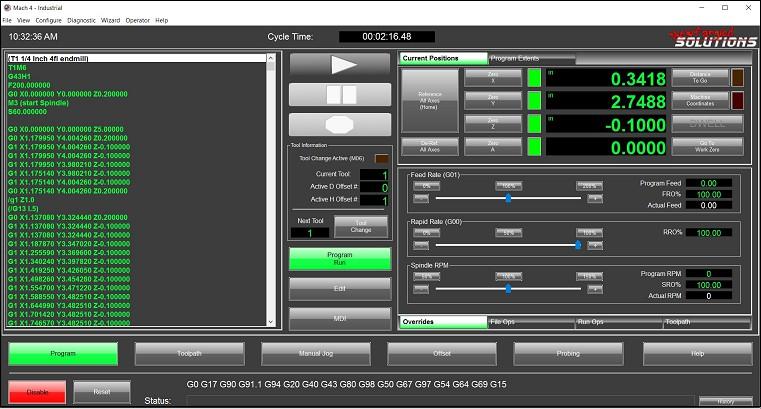
5 *This is only one method of creating a G code program, they can also be manually written or created with a wizard or conversational program. The wizards in Mach are essentially simple graphical CAM programs designed to easily create programs for basic shapes and tasks. 1.4 Typical CNC Cutting Process 2 Screen Layout and Controls The standard Mach4 screen is designed to be easy to navigate for first time users. Figure 2-1 shows the layout of the main page. This is the screen that will be loaded when Mach4Gui.exe is launched and the Mach4Mill profile is selected. Each part will be discussed in more detail in separate sections. 5
6 Figure 2-1: Mach4 screen layout. Menu Bar: Contains drop down menus similar to many programs. Options here range from loading programs, configuration of Mach4 and its plug-ins and exiting the program. Operation Mode Tabs: These tabs select the operation mode of Mach4 and change the layout of the upper half of the screen based on the selection made. Program Execution Controls: Cycle Start, Feed Hold and Stop buttons to control the execution of loaded G Code programs or MDI programming. Reset: The Reset button returns the control to its default state and rewinds the program. Enable/Disable: The enable button does just that, it enables Mach4. The control must be disabled before any configuration changes can be made. Status Bar: Shows the current state of the modal G Code groups. Message History: Displays a window that shows the history of messages displayed in the message bar and recent button pushes. Message Bar: Displays Mach4 errors and comments from a program or script. Operator Control Tabs: Display a variety of buttons for control of loading and editing programs, running of programs, tool path display and jogging. Current Tool Data: Displays current tool number and offset data. Active Profile: Displays the name of the current profile. 6

7 Actual Feedrate: Displays the current actual feed rate, this could differ from the programmed feed rate depending on the setting of the feed rate override controls. Override Controls: Provide control over the feed rate, rapid and spindle speed overrides. Spindle Control: Spindle on/off button. 2.1 Menu Bar The menu bar in Mach 4 consists of drop downs that provide access to, among other things, configuration settings, diagnostics, and offset information File Menu The file menu contains commands for opening and closing G code files and exiting the program (see figure 2-2). Figure 2-2: File menu New Gcode File: Selecting this option opens the G code editor with a new blank file. A program can then be manually typed in by the user and saved for later execution. Recent Files: Display a list of the most recently opened G code files. Select one from the list to load it into Mach4 for execution. Open Gcode File: Opens the Select File dialog, figure 2-3. The user can then navigate to the desired G code file to select and open it in Mach4. 7


8 Figure 2-3: Select file Close Gcode File: Closes the currently loaded G code file. Exit: Exits Mach View Menu The view menu, figure 2-4, contains controls for changing the current display. Figure 2-4: View menu Load Screen: Opens a dialog that allows the user to choose a new screen, or display. Full Screen: Puts Mach4 into full screen mode. Mach4 s display will be enlarged to cover the entire display. Fixture Offsets: Displays the fixture offset table, more information is available in the fixture offset section of this manual. Tool Table: Displays the tool offset table, more information is available in the tool offset section of this manual. 8

9 Windows: Provides options for what toolbars are displayed when in the screen editor mode. The screen editor and its associated functions are explained in the customization manual Configure Menu The configure menu, figure 2-5, provides access to Mach and Plugins configurations. Configuration settings are disabled when Mach4 is enabled. To allow access to these settings, first disable the controller. More detailed information on these settings can be found in the Mach4 CNC Controller Configuration Manual. Figure 2-5: Configure menu Select Motion Dev: Use this menu option to select the external motion device that is to be used. Mach: Opens a window that displays all of Mach4 s configuration settings. This is where all motor and input and output settings are entered. Plugins: Opens a window that lists all installed plugins and provides access to each plugin s configuration settings Diagnostic Menu The diagnostic menu, figure 2-6, provides functions for logging and viewing the status of inputs and outputs. Any installed plugins may have their own diagnostic, varying the contents of this menu based on the machine configuration. Some of the options shown may not be discussed in this manual as they are 3rd party plugin diagnostics. The menu items should be covered in detail in the manual provided by the developer of the plugin. 9

. Any installed wizards can be found here.")
10 Figure 2-6: Diagnostic menu Logging: Opens the logging facility. This is handy error checking tool that logs events in Mach4 in real time. The machine builder can choose what gets logged, so each machine may log events differently. Modbus: Opens a window that shows the current state of Modbus communications. Regfile: Opens a window that displays the current value of a variety of registers and variables in Mach4. The contents and range of what is displayed here will vary with each machine build Wizard Menu The wizard menu, figure 2-7, provides access to the pick wizard window (figure 2-8). Any installed wizards can be found here. A wizard is a small program that allows a user to easily generate G code for common or moderately complex machining processes. Wizards and their capabilities can be as varied as the programmers that write them. Figure 2-7: Wizard menu 10


11 Figure 2-8: Load wizard window Operator Menu The operator menu, figure 2-9, provides the operator with options for editing the Mach4 interface and Lua scripting. The screen editor and an overview of Lua can be found in the customization manual. Figure 2-9: Operator menu Lock: Locks the screen from being edited, a password is required to unlock. Unlock: Unlocks the screen for editing, a password is required. Edit Screen: switches Mach4 to the screen editing mode, see figure


12 Figure 2-10: Mach4 screen editor Edit/Debug Scripts: Opens the Lua editor for editing scripts saved as macros, such as custom M codes. Restore Settings: Lua Script: Displays the Lua script that controls the screen Help Menu The help menu, figure 2-11, is where the operator will find the About page, figure Figure 2-11: Help menu About: Opens a window that displays information about Mach4 and the computer it is installed on. The about screen indicates what version of Mach4 is installed, Lite, Hobby, Industrial, etc. 12

13 Next is the version number, followed by the build number. The PCID is required for licensing. The PCID is based on the configuration of the computer Mach4 is installed and the license will be locked to that PCID / computer system. Copy the PCID number by clicking on the Copy ID To Clipboard button. Use the Load License File button to load a license file received from Artsoft. Figure 2-12: About window Operation Mode Tabs The operation mode tabs allow the user to navigate between program run, manual data input (MDI) and diagnostics. Click on a tab to change the view in Mach4 and change modes Program Run Tab The program run tab, figure 2-13, is the default on startup. This tab displays the current G code file, a plot of the tool path and current position. 13

14 Figure 2-13: Program run tab Operation Mode Selection: These are the tab markers, select the desired tab by clicking on its name. G Code Window: Displays the current G code file. Go to Zero: Moves machine to X0, Y0 in the active fixture offset. Current G Code File: Displays the file path and name of the current G code file. Position Display Mode Selection: Changes the contents of the position display. The To Go button changes the display to show the distance to go to the programmed point. The Machine Coordinates button changes the display to show the machine coordinate system. The LED above each button will light up when the button is activated. If neither LED is on the display shows the current position in the active fixture offset. Limit Override: If a limit switched is tripped motion is disabled. This can cause a problem trying to move the machine off the limit. The limit override essentially ignores the limit switches until they are deactivated. Extreme caution should be used when activating the limit override, it is possible to overrun the switch and cause damage to the machine. Wizard Controls: The Load Wizards button opens a window that displays all the installed wizards available to the user, select one and press OK to run the wizard. Load Last Wizard loads the last wizard that was run. Soft Limits: Activates or deactivates the soft limits. Soft limits are exactly as the same implies, software limits to contain machine motions. These are usually set just inside of the actual limit switches. Soft limits are set up in the Homing/Soft limits tab in the Mach configuration. 14
15 Reference All: References/Homes all axes in the order set on the Homing/Soft limits tab in the Mach configuration. The axes will move to the home switches and machine zero set. Zero Axis: The zero axis buttons will set the current position to zero in the active fixture offset. This sets the active fixture offset and will over write any data that was entered previously. Reference Status LEDs: When an axis is referenced or homed its status LED will change from red to green. Position Display: The digital readouts (DROs) display position data as selected by the display mode buttons. Tool Path Window: The tool path window displays the programmed path for the currently loaded G code file. Below it are some basic controls for the display. Regenerate Tool Path: This button regenerates or refreshes the display. When pushed the tool path will be recalculated with any changes. Display Mode: This button toggles the display of the soft limits in the tool path window. Showing the extents of the soft limits can provide visual reference of where the program is in the machine travel and if it fits. Jog Follow: This button toggles how motion is displayed in the tool path window. With jog follow off the tool path stays stationary and the red lines showing the tool position moves around. When on, the tool position stays centered on the window and the tool path moves around. For large parts this mode can be used to view the tool path in more detail MDI Tab Manual Data Input, or MDI, is a mode that allows the user to manually type in blocks of G code to be executed. A block is a single line of G code containing multiple words, each started with a letter or symbol. The code is executed by pressing the cycle start button. 15

16 Figure 2-14: MDI tab Operation Mode Selection: These are the tab markers. Select the desired tab by clicking on its name. Reference All: References/Homes all axes in the order set on the Homing/Softlimits tab in the Mach configuration. The axes will move to the home switches and machine zero set. Zero Axis: The zero axis buttons will set the current position to zero in the active fixture offset. This sets the active fixture offset and will over write any data that was entered previously. Reference Status LEDs: When an axis is referenced or homed its status LED will change from red to green. De-Ref All Axes: This button sets all axes to an un-referenced state. Manual Data Input Window: Manually input G code to be executed in this window. Multiple lines can be entered. The up and down arrows to the left scroll through the history of executed code. Position Display Mode Selection: Changes the contents of the position display. The To Go button changes the display to show the distance to go to the programmed point. The Machine Coordinates button changes the display to show the machine coordinate system. The LED above each button will light up when the button is activated. If neither LED is on the display shows the current position in the active fixture offset. Verify: Sends the machine to the home position, using the homing sequence, however the home position is not set. The end position of the sequence is compared to the previously found home 16
 display position data as selected by the display mode buttons.")
17 position when the machine was referenced. This is used to verify that the switches have not moved or steps been lost in running the machine. Position Display: The digital readouts (DROs) display position data as selected by the display mode buttons. Tool Path Window: The tool path window displays the programmed path for the currently loaded G code file. It does not display the path of the code entered in the MDI window, it will show the axis motion in real time when MDI code is executed Tool Path Tab The tool path tab, figure 2-15, is a simple display with a tool path window dominating the screen. Figure 2-15: Tool path tab Operation Mode Selection: These are the tab markers. Select the desired tab by clicking on its name. G Code Window: Displays the current G code file. Position Display: The digital readouts (DROs) display position data as selected by the display mode buttons. There are not position display mode buttons on this tab, the display will be changed based on the state of the buttons on the Program Run or MDI pages. Tool Path Window: The tool path window displays the programmed path for the currently loaded G code file. 17

18 Diagnostic Tab In the diagnostic tab, figure 2-16, the operator can view the status of inputs and outputs as well as individual axis homing. Figure 2-16: Diagnostic tab Operation Mode Selection: These are the tab markers. Select the desired tab by clicking on its name. Input Status LEDs: LEDs show the status of a variety of inputs to Mach4. Output Status LEDs: LEDs show the status of a variety of outputs from Mach4. Axis Homing: Buttons to home individual axes and status LEDs to show the reference status. 2.2 Operator Control Tabs These tabs give the operator control of G code file loading and editing, program execution option, tool path and jogging File Ops Tab The file operation tab, figure 2-17, displays controls to affect the current G code file. Here the operator can select which file to load, where to start program execution and edit the G code file. Figure 2-17: File ops tab Operator Control Selection: These are the tab markers. Select the desired tab by clicking on its name. Edit: The edit button opens the current G code file in the G code editor. The operator can then make changes to the program. When the editor is closed the G code file is reloaded into Mach4. 18

19 Open Recent File: Opens a window that displays a list of the most recently loaded G code files. A file can be selected to be loaded into Mach4. Close File: Closes the current G code file. Load File: Opens a window to search for a G code file to be loaded into Mach4. Run From Here: Opens a wizard to aid in starting program execution from anywhere in the program. This function is described in greater detail later in this manual. Current Line: Displays the current line in the G code file. This is the line being currently executed by the controller. Set Next Line: Sets the line to start program execution from Run Ops Tab The run operations tab, figure 2-18, gives the operator control of how a G code file is executed. Options such as single block, block delete, and optional stop can be turned on or off. The program can be rewound or run in reverse. Figure 2-18: Run ops tab Operator Control Selection: These are the tab markers, select the desired tab by clicking on its name. Rewind: Rewinds the program to the first line. Single Block: Activates single block mode, the LED will light when active. In single block mode Mach4 will execute only one line, or block, of code for every press of the cycle start button. Reverse Run: Flood Coolant: Turns on the flood coolant output. 19

20 Optional Stop: When activated program execution will pause at M01 in the program. Block Delete: It is possible to skip lines, or blocks, or a program using the block delete. When activated any block starting with a slash, /, will be ignored by Mach4. Mist Coolant: Turn on the mist coolant output Tool Path Ops Tab The tool path operation tab, figure 2-19, contains tools for controlling the tool path display. Figure 2-19: Tool path ops tab Operator Control Selection: These are the tab markers. Select the desired tab by clicking on its name. Regenerate Toolpath: Reloads the program and recalculates the tool path. Display Mode: Toggles the display of the soft limits. Jog Follow: When active the center of the tool is locked to the center of the tool path display. The display will follow tool movement Jogging Tab The jogging tab, figure 2-20, displays controls for jogging the machine s axes and changing the jog mode. 20
21 Figure 2-20: Jogging Tab Operator Control Selection: These are the tab markers. Select the desired tab by clicking on its name. Jog Buttons: Buttons to jog X, Y, Z and A axes. Cycle Incremental Jog Distance: In incremental jog mode each press of an axis jog button will move the machine on a specified distance, this button cycles through the distances defined in the general configuration. The current step distance in shown in the adjacent DRO. Toggle Jog Mode: Toggles between continuous and incremental jog modes. Jog Rate: Sets the velocity for continuous jog as a percentage of the machine s max velocity. Toggle Keyboard Jog: Turns on/off the ability to jog using the keyboard. 3 Getting Started How to start Mach4 will vary depending on the installation. In all cases there will be a Mach4GUI.exe located in the Mach4 folder usually located on the C drive. Some machines may have a shortcut to this executable on the desktop. When Mach4 is started the user will be presented with an option to choose a profile, figure

22 Figure 3-21: Select profile window In the select profile window, the user can choose a profile to open, create a new profile from scratch, copy an existing profile, restore a profile or delete a profile. Once a machine is set up, using a shortcut to run a specific profile is often convenient. Create a shortcut to Mach4GUI.exe on the desktop. Right click on the shortcut and select properties. In the properties dialog, figure 3-2, the Target is the file that will be run. This should read the location of Mach4GUI.exe. Add /p profilename to the end of this line, replacing profilename with the name of the desired profile. The shortcut will open Mach4 into the named profile. 22

23 Figure 3-22: Shortcut properties dialog 3.1 Enabling the System Once open the user will be presented with Mach4 in the disabled state. The system must be enabled before any operation of the machine can take place. Enable the controller by pressing the flashing green enable button in the lower left corner of the screen. Figures 3-3 and 3-4 show Mach4 in its disabled and enabled states, respectively. 23

24 Figure 3-23: Mach4 main screen in disabled state Figure 3-24: Mach4 main screen in enabled state Notice that when Mach4 is disabled buttons that control motion or program execution are unavailable to the user, they are greyed out. On this main screen these controls are Ref All Home, Goto Zero, Cycle Start, and Reset. Once enabled these controls are made available to the user. 24

25 3.2 Home the Machine The vast majority of machines running Mach software use incremental encoders for position feedback, some have no position feedback to Mach. As a result, when Mach4 is started and enabled, the control has no idea where the machine is positioned. To determine the location of the machine Mach4 uses a referencing sequence started by pressing the Ref All Home button. Before pressing the reference all button ensure that no axis is on its home switch, jog the machine away from the switch if necessary. Each axis is sent to its home position, signaled by the activation of a switch, in the order set in the homing and limits configuration. When the home position is found the DROs in Mach will be updated to the desired machine position, usually 0 for all axes. The machine is now ready to run. 3.3 Jogging Manual jogging allows the operator to move the machine around using on screen controls, figure 3-5, the keyboard, or an attached control panel / pendant (see figure 3-6). To view the onscreen controls, click on the jogging tab on the screen. Figure 3-25: Jogging tab Jogging is enabled whenever the controller is enabled and a program is not being executed. However, keyboard jog defaults to off for safety. The default screen provides controls for jogging 4 axes; X, Y, Z, and A. These controls work just like a physical button, in continuous jog mode the machine will move as long as the button is held down. Keyboard jogging is deactivated by default, this feature can be activated by pressing the Keyboard Jog button. The default jog buttons are left arrow for X-, right arrow for X+, up arrow for Y+, down arrow for Y-, page up for Z+ and page down for Z-. There are 2 basic jog modes which are selectable by pressing the Jog Mode button. The current selection will be indicated by an LED. Figure 3-5 shows the continuous mode selected. In continuous mode the machine will move at the specified jog rate as long as a jog button is held down. The jog rate can be changed by moving the slider at the bottom of the jogging tab or by directly typing the desired rate into the DRO in the bottom right corner. The number shown in the DRO is a percentage of the max 25


26 velocity, or rapid rate, of the machine. Continuous mode is useful for moving the machine relatively large distances and rough positioning. When finding the edge of a work piece, locating a hole, or other precision position is required, step jog is much more accurate. In step jog, the machine moves only by the specified increment amount, regardless of how long the jog button is held down. The jog increment can be changed by pressing the Cycle Jog Inc button. This button will change the DRO to the right of it to show the current increment amount. The increment values can be changed on the General tab in the Mach configuration. Figure 3-26: Control panel and pendant examples 3.4 Changing Tools Tool changes will vary depending on machine configuration. Some machines have automatic tool changers, while others require the operator to physically change the tool. Each type of tool changer must be configured properly in Mach4, this is covered in the configuration manual. For automatic tool changers, a Lua script will likely be required to command it or communicate between an external controller and Mach4. Scripting is covered in a separate scripting manual. 3.5 Fixture Offsets Fixture offsets are used to tell the machine where a work piece is located. The values are stored in the fixture offset table, figure 3-6. These values offset the machine coordinate system to create a user coordinate system at the desired point. Offsets are activated by calling the corresponding G code in the program. See the programming manual for details on calling fixture offsets. G54-G59 are the standard fixture offsets with G54.1 P1 through G54.1 P248. There are also two additional offsets in the table Work Shift and Head Shift. Values in work shift will shift the entire table, this can be useful when test running programs (the Z axis can be lifted slightly more than the max depth of the program to run above the part) or making adjustments without changing offset values. The work shift is always active, so when changed, it is important to remember a change has been made. Changing fixture offsets in the 26
27 program will not deactivate work shifts. Head shift is used for multi head/multi spindle machines and not covered in this manual. Figure 3-27: Fixture offset table There are a variety of ways to find a work piece in the machine; edge finding is probably the most commonly used method and will be covered in this manual. Probing is a great method when available, sometimes all that is required is to visually jog the machine to position and zero it. The accuracy required is determined by the required part accuracy Edge Finding Edge finders, figure 3-7, come in many shapes and styles, each specialized for specific applications. The type used for examples in this manual are highlighted in figure 3-7. The shaft diameters can vary, but the tip diameter is inch, making the math for calculating the offsets very easy. 27


28 Figure 3-28: Edge finders An edge finder is used by spinning it at a low RPM, usually 1000 is perfect. The tip of an edge finder is held in place under spring tension and is moveable. In figure 3-8 all the edge finders are shown with the tip offset. When spinning in free space, away from a part edge, the tip will move away from the center line and wobble. Choose an axis to touch off first. For this example, we will use the X axis and make the left edge of our part the fixture zero. Jog the machine to a position that will allow the edge finder to come down below the surface of the part just to the left of the work piece, see figure 3-9 position A. Figure 3-29: Using an edge finder 28

29 When clear of the work piece, the edge finder can be moved down in the Z axis until the tip is just below the surface of the part, about.100 inch. The tip will be wobbling and appear bigger than it actually is. Jog the machine, slowly and carefully, towards the part. When the edge finder just starts to touch the part stop and switch to incremental jog. A larger step amount of about inch is appropriate here, move one increment at a time until the edge finder starts to look like figure 3-9, position B. As the machine moves closer to the edge, the edge finder will start spinning more truly. As the machine gets closer, the edge finder will get more sensitive to movement. Turn the step increment down to inch and move in one increment at a time. When the correct position is reached, the edge finder will break, as shown in figure 3-9 position C Inputting Fixture Offset Values Now to input a value into the fixture offset table. There are a couple ways to do this. The value can be calculated manually and directly typed into the field or the input box can be used to enter values. When using the input box there are three ways to enter data, see figure The first is the Input button. Pressing input enters the value from the input box into the selected offset, over writing any existing value. Next, is the Input + button. Pressing the plus input adds the value in the input box to the value in the selected offset. For instance, if the current offset is 1.5 and.1 is typed into the input box then plus input is pressed the new value of the offset will be 1.6. If input was pressed, the new offset would be.1. Play around with these input functions to get familiar with them and how they function. The third button is the measure button. This button will do the math for us. Figure 3-30: Fixture offset table Let s first input the offset using the Input and Input + buttons. The value we re looking to enter into the offset is the machine position of the X axis at the desired zero location on the work piece. The position we are looking for is the location of the edge of the part. The edge finder was used to find the edge, but the radius of the edge finder has to be accounted for, see figure

30 Figure 3-31: Touch off location for inch diameter edge finder Select the desired offset. In figure 3-10 the X offset of G54 is selected. In the input box type in the position displayed in the X axis machine position DRO and press the input button. The data will be written to the offset. Now turn off the machine position to see the fixture offset position in the DRO. If everything was entered correctly, the X DRO should now read If not, make sure the desired fixture offset is active by commanding it in the MDI mode. Now, although the data was input correctly to obtain zero, the edge finder radius has not been accounted for. The position we are actually looking for is as shown in figure To make this adjustment type into the input box and press the Input + button. The X DRO will update to show , this is the correct position. Double check your offset data by commanding the fixture offset in MDI to activate it, jog the machine so the edge finder is just above the surface of the part and move to X0.0000; the edge of the part should be at the center of the edge finder. The next method, and more reliable as human error is reduced, is to use the measure button. With the edge found with the edge finder, type in the desired position, in this case it is and press the Measure button; the offset value is calculated and input into the offset. The X axis DRO will now read The math is completed by Mach4, just input the value that the DRO should read at the current position. Repeat the same process to find the Y axis position. The Z axis will be a little different. A good way to find the Z axis position is to use a fixed tool. The edge finder is a good one, and a gage block. Move the machine above the part and jog down slowly. When near the gage block height, use incremental mode to avoid crushing anything. Slide the gage block under the edge finder, if it slides freely pull it out and step the Z axis down. Keep stepping down until the gage block just hits and won t slide under. Go back up one increment, usually around but that will vary with desired accuracy. This is the touch off 30

31 position. Entering the offset data is the same as described above, only this time instead of taking the edge finder radius into account the gage block thickness must be used. Select the Z axis offset in the fixture offset window, enter the gage block thickness in the input box and press the Measure button. Activate the offset and check the position DRO. The Z axis should show the gage block thickness. 3.6 Tool Length Offsets Tool length offsets are used to tell the machine how long a tool is or where it is in relation to the rest of the machine or work piece and are stored in the tool offset table, figure There are as many ways to touch off tools are there are CNC machinists, this manual can t attempt to cover them all. The examples used here are to demonstrate how the offset system works. Figure 3-32: Tool offset table There are a couple of methods for touching off the tool. A gage block can be used as described for setting the Z fixture offset in the previous chapter. A piece of paper can be used in place of a gage block, using the same procedure. Electronic blocks and touch off devices are available, as are blocks with indicators, and even automatic tool setters (see figure 3-13). Another great method for high production environments is an offline tool pre-setter outside the machine. 31

32 Figure 3-33: Types of tool setting devices Master Tool Setting up a master tool is a great way to do tool offsets, especially on a knee mill type machine. This method involves having a tool at a fixed length and a tool offset value of zero. An edge finder is great for this. Select a holder and lock the edge finder at a fixed length. Use the edge finder to set a work offset at the top surface of a work piece or any flat surface to touch all the tools off. This allows the operator to set up a library of tools with set offsets. When a new part is set up, just touch off the Z fixture offset and start machining. All the tools will follow the master tool. Make sure to disable tool length offsets (G49) or activate the tool length offset for the master tool (G43 Hhh, where hh is the offset number of the master tool) before setting the fixture offset for touch off surface. Once a surface is found using the master tool and the fixture offset entered, bring each tool down to the surface using the same method, some type of gage block or tool setter of known height. The position shown in the Z axis DRO will show the difference in length between the master tool and the tool being touched off. There are a few options for inputting the value into the tool offset table, just like when setting fixture offsets. The value can be entered directly into the offset. A value can be typed into the input box at the bottom and then the Input button will over write the existing data with the value in the box, the Input + button will add the value from the input box to the existing value, and the Measure button will calculate the offset value using the data in the input box as the desired position. For this example, type in the gage block thickness then press the Measure button. The value will be set. Double check the data by activating the current tool offset, MDI G43 Hhh where hh is the offset number of the tool being touched off. The Z axis DRO should read the gage block thickness if done correctly. 32
33 3.6.2 Tool Length from Gage Line Measuring the actual tool length from the spindle gage line (figure 3-14) is the preferred method when using automatic tool setters and manual electronic/light-up or indicator style setters. It is also particularly suited to machines with fixed tables like bed mills, vertical and horizontal machining centers, gantry mills, and routers, etc. The distance from the spindle gage line to the measurement point must be known. When tools are touched off, the offset value will be the distance from the tip of the tool to the gage line. Because the offset is simply a length measurement and not a machine position, the offset value can also be measured outside the machine on a tool pre-setter. Figure 3-34: Gage line and tool length To use this type of tool offset system, a fixed point in the machine should be chosen to measure tools. A great position is the table of a bed mill. The distance from the spindle gage line to this point must be found. One way to do this, is remove any tool from the spindle then jog the Z axis down. Generally, the spindle cannot reach the table, but a 4 block usually provides enough height to obtain a measurement. Use the same procedure as was used when touching off tools, step the spindle down in small increments until the block just slides under. The machine position Z axis DRO will read the distance the spindle traveled down to reach this point. Record this number. For our example machine, let s say it is If the gage block used is the same one that will be used to touch off tools, then this is the number that will be used for tool touch offs. If not, subtract the gage block thickness ( = ) to get down to the table and then add back the height of whatever gage will be used. 33
34 Now, we will explain how to touch off tools. A fixture offset can be set at this position or a macro can be created. If a fixture offset is used, it must be active and tool height offsets inactive when touching tools to get the correct data. With this set up, the user position Z axis DRO will read the length of the tool. This number should be directly input into the tool height offset. With a macro (see customization manual for more detailed information) a button like the Auto Tool Zero button can be used to do the math. The macro would take the absolute value of the difference between and the machine position when the button is pressed. The resulting number will be the length of the tool. For instance, if a tool is touched off and the Z axis machine position is the tool length, tool height offset, is = So, the tool in the spindle is long, which is the tool offset. This method is a little more complicated to set up, but once set can be a time saver. Fixture Z offsets can be set with any tool as long as the correct height offset is activated. 3.7 Tool Diameter Offsets Tool diameter offsets allow the operator to make adjustments to the finish size of parts provided that the program contains the proper codes to activate and use the diameter offset. Data is entered in the Dia column in the tool offset table, figure Detailed information on the programming and use of tool diameter offsets can be found in the cutter compensation section of the Mach4 programming guide. 3.8 Tool Wear Offsets Cutting tools wear during use. This is true for everything from steak knives in the kitchen to high tech coated carbide metal cutting tools. Wear and dull cutting edges induce deflection in the cutting tool and machine that can throw off the precision of a part being cut. Mach4 provides wear offsets for both tool length and diameter to compensate for this deflection, and sometimes actual reduction in length or diameter of the cutting tool. These wear offsets are found in the tool offset table, figure 3-12, in columns labeled Length Wear and Dia Wear. When a tool offset is called, Mach4 adds the wear offset to the set offset value to determine the actual offset to be used. Using wear offsets is recommended for making small adjustments over making changes to the other offsets. For example, a CNC mill is facing a steel part and the finished thickness is too big. The operator adjusts the tool length offset, , to cut deeper. The next part is an aluminum one, the operator doesn t remember the old offset so just faces the part and it is too small. The difference in material hardness can affect the finished size of the part. In this case, the operator would have had to record the previous length offset or remember the adjustment amount. Using wear offsets, the operator could just zero out the wear offset, or even use it to cut a little oversize and work down without doing a lot of math. The original offset is never changed, unless the tool is changed. Wear offsets are a valuable resource, learn them, understand them, and use them. 3.9 Tool Information During operation the current tool information is displayed on the main screen, figure This section of the screen shows the current tool number and its diameter and height offset information. It is a quick way to check that the correct data has been input into the tool offset. During a tool change the Tool Chng LED will blink, indicating that the machine is either changing the tool automatically or waiting for the user to manual change tools and press the cycle start button. 34
35 Figure 3-35: Tool information The Tool DRO shows the currently selected tool, this DRO will be updated at every tool change. It can also be changed by the user by clicking on the DRO, typing in the desired tool number, and pressing enter or return on the keyboard. The Diameter and Height offset DROs will update to show information for the selected tool number. These DROs are read only and not user editable Creating Programs Programs are required for automatic operation of the machine. The most common format is G code. This type of programming uses a system of G codes (G01, G10, G81, etc.) to specify the desired function. Position codes (X, Y, Z, etc.) are used to tell the machine where to go, or where an operation is to take place. Other codes starting with M, T, S, F and a few others enable control of just about every aspect of the controller and machine. The Mach4 Programming Guide is a complete description of the required G code format. Programs can be created by using the wizards, a CAM (computer aided manufacturing) system, or by manually typing it. There are a variety of CAM systems that can be used for generating programs from 2D or 3D drawings. When CAD models are available using a CAM package is usually the best and quickest way to generate a G code program for machining. However, some of these software packages can be very expensive. For this reason, Mach4 includes the ability to run wizards, a form of conversational programming. Wizards can be created by anyone with some computer programming skill for just about any task needed Mill Wizard Mill Wizard provides the user with a set of tools to generate G code files for common milling jobs. The close link with Mach4 allows created G code to be loaded into Mach4 with the push of a single button. 35

36 Mill Wizard can create programs with multiple tools and features. Features and shapes include rectangles, circles, links, slots, hole patterns, engraving, gears, splines and more. Figure 3-16 shows the main screen and all the available operations. Jobs can be created using the stock materials or the user can add special materials to the table. Tools can be added to a table for later use. Operations can be modified and re-ordered as desired. Complete documentation is provided in the help menu of the software. The follow figures give a basic idea of what the software looks like. Figure 3-36: Mill Wizard main screen 36


37 Figure 3-37: New job window, select material, units, etc. Figure 3-38: New tool window, select tool and set feed and speed 37

38 Figure 3-39: Circular pocket wizard 38


39 Figure 3-40: Hole circle wizard Figure 3-41: Text engraving wizard 39
 Manual Data Input (MDI) mode allows the operator to manually enter G code to be executed.")
40 Figure 3-42: Rectangle cutting wizard, cut inside, outside or groove 4 Running the Machine 4.1 Manual Data Input (MDI) Manual Data Input (MDI) mode allows the operator to manually enter G code to be executed. The operator should have a solid understanding of G code and machine programming before attempting to command the machine using the MDI mode. This is useful for activating or deactivating fixture offsets, tool offsets, positioning modes, tool changes, moving to known positions, etc. In Mach4, MDI programs can be multiple lines and a history of commands is saved that can be navigated using the up and down arrows adjacent to the MDI window. 40

41 Figure 4-43: MDI screen To enter code into the MDI window, select the window and type in the desired code. Press the Cycle Start button to execute the code in the window. Once executed, the code will be stored in the history where it will remain until Mach4 is shut down. Press the up arrow on the left of the MDI window to scroll through the history. The most recent code is shown first. The tool path window on this page shows the tool path of the currently loaded G code file and not the MDI program. Some examples: Change to tool number 10: T10 M6 Activate tool length offset number 6: G43 H6 Move to machine zero position: G53 G90 G0 X0 Y0 Z0 Move to part zero position: G54 G90 X0 Y0 Z0 4.2 Loading a G Code Program G code programs contain code for cutting a part. The first step to running a program is to load it into Mach4. In the File Ops tab in the operator control section of the screen press the Load G Code button. A window will open that will allow the operator to navigate to the desired file and open it. By default Mach4 will show.tap and.nc files. Any basic text format can be opened and the default file types can be changed in the Mach configuration on the General tab. When the file loads, Mach4 will quickly run through it to generate a tool path for the tool path window. If there are any major code errors or unknown codes they will be found on this initial run through. The tool path window will show the actual tool path including cutter comp and any other adjustments made in the program. Check it to make sure it looks as intended before running. 41
42 4.3 Viewing the Tool Path The tool path window shows the programmed path exactly as it will be run by the machine. It is possible to pan rotate and zoom the tool path window using the mouse. Move the mouse pointer into the tool path window and perform the following: Rotate Left click and drag Pan Left + right click and drag Zoom Right click and drag or scroll wheel Reset View Double left click 4.4 Editing a G Code Program To edit the currently loaded G code file press the Edit G Code button in the File Ops tab. Mach4 will open the file in the included G code editor: GC Edit. When the desired changes are made, save the file and close the window. Mach4 will re-load the file and re-generate the tool path. 4.5 Closing a G Code Program To close a G code program, press the Close G Code button in the File Ops tab. 4.6 Executing a G Code Program Cycle Start Pressing the cycle start button will start program execution from the current line shown in the File Ops tab. The program will run until a program pause or end G code is read or execution is stopped by the operator Feed Hold The feed hold button will immediately pause the program, press cycle start to continue. Feed hold will only pause axis motion. If the spindle is running it will stay on and any active outputs will remain active (coolant, air blow, etc) Stop The stop button will immediately end program execution. All motion will stop as well as the spindle and other outputs. This is similar to commanding a program stop in the G code program. Although program execution is halted by pressing the stop button, the program is not rewound Reset To rewind a program back to the beginning press the reset button. This will also return the controller to its default state Starting from the Middle of a Program There are a couple ways to start execution from a point other than the beginning of a program. If the desired start point is a safe start line or other safe position, not including any motion, the desired start 42

43 line can be selected and cycle start pressed. Select the desired start line in the G code window and then press the Set Next Line button. When the cycle start button is pressed the program will begin execution from this selected line. Programs can also be started from any position in the program, including in the middle of a cut. To do this, select the point to start by scrolling through the G code program in the G code window and select the desired line. Manually jog the machine close to the start point. Next, press the Run From Here button in the File Ops tab. A window will open, figure 4-2, to start the process of restarting the program. Figure 4-44: Run from here window In the run from here window, there is a position read out showing distance to go. These distances are how far the machine needs to travel to reach the start point. Before starting execution, the machine must be moved to the start point. The axes can be moved using the controls in the Move Axis to Start Position section of the window. Enabled axes will be available for selection. Select one or multiple axes to move and press the Move Selected button. The selected axes will move to their start positions. Another button, Move Unselected will move the unselected axes. Use this button to move any remaining axes to their start positions. Once the machine is in the start position, press the OK button. Mach4 will scan the preceding part of the program to get the machine into the proper state: coolant/spindle on or off and setting up cutter comp if active. Press cycle start to start machine motion and run the rest of the program. 5 Help, I ve Crashed and now my machine won t move. Inevitably, as careful and conscious as we may be, there will be a crash or run in with hard limit switches. Recovery from these situations can range from careful jogging to removing tools and debris before moving (try to avoid the latter). As always, prevention is better than recovery, both will be discussed. 43

44 5.1 Limit Switches Limit switches are physical switches that mark the end of a machine s range of motion. Sometimes one or more of these will double as a home switch. The hard limit switches are basically the last line of defense before major damage occurs. Without these switches the machine could slam into a hard stop at the end of travel or even send the table right off the end of the rails, depending on the configuration. Running a machine without limit switches is risking damage to ball screws and nuts, bearings, castings, people, floors and walls. When Mach senses that a limit switch is activated it immediately disables all motion. In this state jogging is disabled. At first it can seem impossible to recover from this situation. On small machines one solution could be to turn the ball screw or slide the axis by hand, on bigger machines this is not possible. In this case jogging the machine off the limit is the only option. Figure 5-45: Limit override on program run screen When a machine is on a limit switch it can be jogged by temporarily overriding the limit switches. Press the Limit Override button on the program run screen, figure 5-1. This will re-enable axis motion and jogging so the machine can be moved away from the limit switch. As soon as the switch is deactivated the limit override is automatically turned off. When the limit override button is pushed the machine can be moved in any direction and regardless of the state of the limit switches. Exercise EXTREME caution to avoid serious damage to human operator or machine. Check and double check which axis should be moved and in which direction. Start movement with a very small move, just bump the axis, to verify your choice of direction is correct. Then move the machine the rest of the way off the switch. 44

45 5.2 Soft Limits Running into machine hard limits can be prevented by using soft limits. Soft limits are software end of travel switches. They are generally set up by the machine builder to be about ¼ to 1 inch from the physical switch depending on machine size, velocity and acceleration. When an axis is moved into the soft limit it is decelerated to a stop. Generally there is a deceleration window of about a ½ inch. Inside this window axis velocity is reduced. When a machine runs into a soft limit it can simply be jogged the other way, no risky limit override button. Soft limits can be displayed in the tool path display by pressing the Display Mode button. The soft limits show up as dashed yellow lines, figure 5-2. When the cycle start button is pressed to run a program, Mach automatically checks if the tool path extends beyond the soft limits, if it does a warning is issued. Figure 5-46: Soft limits shown in tool path display 5.3 Crash!!! It happens to everyone who has ever run a CNC machine. The machine is running great, the part is being cut exactly as we expected. Then, CRASH. A tool breaks, the work piece comes out of the vise or chuck, the machine hits a clamp, or any number of seemingly impossible feats for a machine to perform. Sometimes it s very minor, sometimes it s very serious. These moments are extremely frustrating for operators and programmers, it is usually best to take a minute to survey the situation before taking action. Before attempting to move a machine that has been crashed take a good look at everything involved. Make sure there is no major damage to the machine, if there is don t try to jog it which could cause even more damage. If something happened while cutting a part, check the tool and where in cut it stopped. Sometimes it is best to loosen a tool in its holder so the Z axis can be jogged up to remove 45
Ultimate Screen Reference Guide
 MACHMOTION Ultimate Screen Reference Guide 8/11/2011 Everything you need to know to use and setup the MachMotion Ultimate Screen. MachMotion Version 1.0.2 2 P a g e Copyright 2011, MachMotion.com All rights
2000 Series Mill / Router Operating Manual
 2000 Series Mill / Router Operating Manual 1. Introduction 1.1 Control Startup To open the control software double-click on the profile icon on the desktop. Control Icon 1.2 Overview This manual gives
Mach4 CNC Controller Screen Editing Guide Version 1.0
 Mach4 CNC Controller Screen Editing Guide Version 1.0 1 Copyright 2014 Newfangled Solutions, Artsoft USA, All Rights Reserved The following are registered trademarks of Microsoft Corporation: Microsoft,
Software designed to work seamlessly with your CNC Masters machine. Made to work with Windows PC. Works with standard USB
 Software designed to work seamlessly with your CNC Masters machine Made to work with Windows PC Works with standard USB Clutter free interface. The software is engineered for the machine so you don t have
Lathe. Lathe Control Operating Manual 1000 Series Set Lathe X axis Part Zero
 Lathe Lathe Control Operating Manual 1000 Series Set Lathe X axis Part Zero Lathe Control Operating Manual 1000 Series 1. Introduction 1.1 Control Startup To open the control software double-click on the
Standard Mach4 Features included with Tangential:
 MACH4 TANGENTIAL Tangential takes place on one page: Program Run. The Tangential Profile is intended to operate Machinery equipped with a rotational axis independent of, but usually associated in, the
1000 Series Lathe Control OPERATING MANUAL. Specializing in CNC Automation and Motion Control
 1000 Series Lathe Control OPERATING MANUAL Specializing in CNC Automation and Motion Control 2 P age 6/24/15 G0131 This manual covers the operation of the 1000 Series Lathe Control. Formatting Overview:
Coordinate System Techniques
 Coordinate System Techniques In this lesson, we ll show some advanced implications of what can be done with coordinate systems. For the most part, this lesson applies to machining centers. But there are
Mach4 CNC Controller Mill Programming Guide Version 1.0
 Mach4 CNC Controller Mill Programming Guide Version 1.0 1 Copyright 2014 Newfangled Solutions, Artsoft USA, All Rights Reserved The following are registered trademarks of Microsoft Corporation: Microsoft,
COPYCAT NEW FANGLED SOLUTIONS 2/6/2009
 1.0 INTRODUCTION 1.1 CopyCat is a unique wizard used with MACH3. It is not a stand alone program. This wizard will allow you to jog a machine around and create a Gcode file from the movement. 2.0 REQUIREMENTS
FlashCut CNC / Precix Router User s Guide v1.2 Brett Ian Balogh 31.October, Ensure the computer is plugged in. Do not plug the spindle in yet.
 FlashCut CNC / Precix Router User s Guide v1.2 Brett Ian Balogh 31.October, 2011 1. Ensure the computer is plugged in. Do not plug the spindle in yet. 2. Start the computer by pressing the on/off button
Tutorial 1 Engraved Brass Plate R
 Getting Started With Tutorial 1 Engraved Brass Plate R4-090123 Table of Contents What is V-Carving?... 2 What the software allows you to do... 3 What file formats can be used?... 3 Getting Help... 3 Overview
TOOLPATHS TRAINING GUIDE. Sample. Distribution. not for MILL-LESSON-4-TOOLPATHS DRILL AND CONTOUR
 TOOLPATHS TRAINING GUIDE MILL-LESSON-4-TOOLPATHS DRILL AND CONTOUR Mill-Lesson-4 Objectives You will generate a toolpath to machine the part on a CNC vertical milling machine. This lesson covers the following
Conversational Programming for 6000i CNC
 Conversational Programming for 6000i CNC www.anilam.com P/N 634 755-22 - Contents Section 1 - Introduction Section 2 - Conversational Mode Programming Hot Keys Programming Hot Keys... 2-1 Editing Keys...
Profile Modeler Profile Modeler ( A SuperControl Product )
") Profile Modeler ( A SuperControl Product ) - 1 - Index Overview... 3 Terminology... 3 Launching the Application... 4 File Menu... 4 Loading a File:... 4 To Load Multiple Files:... 4 Clearing Loaded Files:...
Profile Modeler ( A SuperControl Product ) - 1 - Index Overview... 3 Terminology... 3 Launching the Application... 4 File Menu... 4 Loading a File:... 4 To Load Multiple Files:... 4 Clearing Loaded Files:...
imach III P2-S CNC Control Pendant
 www.vistacnc.com - 1 - imach III P2-S CNC Control Pendant www.vistacnc.com - 1 - imach III P2-S Pendant Manual v. 3.3.0 www.vistacnc.com - 2 - PREFACE Any machine tool, including computer controlled machine
The ProtoTRAK Parasolid Converter Operating Manual
 The ProtoTRAK Parasolid Converter Operating Manual Document: P/N 28070 Version: 042216 Parasolid for Mills Compatible with offline and SMX ProtoTRAK Control models Southwestern Industries, Inc. 2615 Homestead
OKUMA MACHINING CENTER OPERATORS GUIDE OSP P200M THiNC
 OKUMA MACHINING CENTER OPERATORS GUIDE OSP P200M THiNC OSP P200 Mill Training Rev1 1 OKUMA MACHINING CENTER OPERATORS GUIDE Scope 4 Section 1 Guide to Controls on Operation Panels 5 Section 2 Manual Tool
Mach4 CNC Controller Software Installation and Configuration Guide Version 1.0
 Mach4 CNC Controller Software Installation and Configuration Guide Version 1.0 1 Of 27 Copyright 2014 Newfangled Solutions, Artsoft USA, All Rights Reserved The following are registered trademarks of Microsoft
Mach4 CNC Controller Lathe Programming Guide Version 1.0
 Mach4 CNC Controller Lathe Programming Guide Version 1.0 1 Copyright 2014 Newfangled Solutions, Artsoft USA, All Rights Reserved The following are registered trademarks of Microsoft Corporation: Microsoft,
Craftsman CNC. LinuxCNC. Custom developed for Craftsman CNC Routers
 Craftsman CNC LinuxCNC Custom developed for Craftsman CNC Routers Menu File Load gcode Load a gcode program Recent gcode Shows the 10 most recently opened gcode programs Close gcode Closes the current
imach III P1A-S CNC Control Pendant
 www.vistacnc.com - 1 - imach III P1A-S CNC Control Pendant www.vistacnc.com - 1 - imach III P1A-S Pendant Manual v. 3.3.1 www.vistacnc.com - 2 - PREFACE Any machine tool, including computer controlled
G & M Code REFERENCE MANUAL. Specializing in CNC Automation and Motion Control
 REFERENCE MANUAL Specializing in CNC Automation and Motion Control 2 P a g e 11/8/16 R0163 This manual covers definition and use of G & M codes. Formatting Overview: Menus, options, icons, fields, and
Conversational Programming for 6000M, 5000M CNC
 Conversational Programming for 6000M, 5000M CNC www.anilam.com P/N 70000486F - Contents Section 1 - Introduction Section 2 - Conversational Mode Programming Hot Keys Programming Hot Keys... 2-1 Editing
Mach4 CNC Controller Mill Programming Guide Version 1.1 Build 3775
 Mach4 CNC Controller Mill Programming Guide Version 1.1 Build 3775 Copyright 2014 Newfangled Solutions, Artsoft USA, All Rights Reserved The following are registered trademarks of Microsoft Corporation:
MASTERCAM DYNAMIC MILLING TUTORIAL. June 2018
 MASTERCAM DYNAMIC MILLING TUTORIAL June 2018 MASTERCAM DYNAMIC MILLING TUTORIAL June 2018 2018 CNC Software, Inc. All rights reserved. Software: Mastercam 2019 Terms of Use Use of this document is subject
CNC Programming Simplified. EZ-Turn Tutorial.
 CNC Programming Simplified EZ-Turn Tutorial www.ezcam.com Copyright Notice This manual describes software that contains published and unpublished works of authorship proprietary to EZCAM Solutions, Inc.
dfab Laguna CNC Manual With FANUC Control
 dfab Laguna CNC Manual With FANUC Control 1 Introduction Throughout this manual we use different nomenclature for [HARD KEYS] and (SOFT KEYS). A [HARD KEY] is a button on the CONTROL PANEL (upper panel)
IEEM 215. Manufacturing Processes I Introduction to the ARIX CNC milling machine
 IEEM 215. Manufacturing Processes I Introduction to the ARIX CNC milling machine The image below is our ARIX Milling machine. The machine is controlled by the controller. The control panel has several
OEM Buttons - MachCustomizeWiki
 Page 1 of 8 OEM Buttons From MachCustomizeWiki This list gives the codes to be used in calls of DoOEMButton. If you are using a version of Mach3 prior to 1.90 then to use bunttons in this list that are
Programming Features PERFORMANCE & SPECIFICATIONS
 PERFORMANCE & SPECIFICATIONS Essentials Processor Intel Pentium Instruction Set 32-bit Performance Number of Cores 1 Processor Base Frequency 1.8 GHz Memory Data Storage 1 GB System Memory Installed 2
Using Delcam Powermill
 Written by: John Eberhart & Trevor Williams DM Lab Tutorial Using Delcam Powermill Powermill is a sophistical tool path generating software. This tutorial will walk you through the steps of creating a
Lesson 4 Introduction To Programming Words
 Lesson 4 Introduction To Programming Words All CNC words include a letter address and a numerical value. The letter address identifies the word type. The numerical value (number) specifies the value of
VisualCAM 2018 for SOLIDWORKS-TURN Quick Start MecSoft Corporation
 2 Table of Contents Useful Tips 4 What's New 5 Videos & Guides 6 About this Guide 8 About... the TURN Module 8 Using this... Guide 8 Getting Ready 10 Running... VisualCAM for SOLIDWORKS 10 Machining...
Welcome to. the workshop on the CNC 8055 MC
 Welcome to the workshop on the CNC 8055 MC Sales Dpt-Training: 2009-sept-25 FAGOR CNC 8055MC seminar 1 Sales Dpt-Training: 2009-sept-25 FAGOR CNC 8055MC seminar 2 This manual is part of the course for
CHAPTER 1 COPYRIGHTED MATERIAL. Getting to Know AutoCAD. Opening a new drawing. Getting familiar with the AutoCAD and AutoCAD LT Graphics windows
 CHAPTER 1 Getting to Know AutoCAD Opening a new drawing Getting familiar with the AutoCAD and AutoCAD LT Graphics windows Modifying the display Displaying and arranging toolbars COPYRIGHTED MATERIAL 2
How to Make a Sign. Eagle Plasma LLC. Accessing the included step by step.dxf files
 Eagle Plasma LLC How to Make a Sign Accessing the included step by step.dxf files The following tutorial is designed to teach beginners, screen by screen, to create a simple sign project. In this lesson
9000 CNC 9000 CNC: THE NEW STANDARD OF CONTROL. INTUITIVE EFFICIENT PRODUCTIVE
 3D Solid Model Graphics Solid Model with Tool Path Overlay 9000 CNC 9000 CNC: THE NEW STANDARD OF CONTROL. At Milltronics we are constantly refining our controls to simplify operation, shorten setup times
RhinoCAM 2018 MILL Quick Start Guide. MecSoft Corporation
 2 Table of Contents About this Guide 4 1 Useful... Tips 4 2 About... the MILL Module 4 3 Using this... Guide 5 Getting Ready 6 1 Running... RhinoCAM 2018 6 2 About... the RhinoCAM Display 6 3 Launch...
Mach4 CNC Controller Lua Scripting Guide
 Mach4 CNC Controller Lua Scripting Guide 1 Copyright 2014 Newfangled Solutions, Artsoft USA, All Rights Reserved The following are registered trademarks of Microsoft Corporation: Microsoft, Windows. Any
What's New in BobCAD-CAM V29
 Introduction Release Date: August 31, 2016 The release of BobCAD-CAM V29 brings with it, the most powerful, versatile Lathe module in the history of the BobCAD-CAM software family. The Development team
Edgecam Getting Started Guide
 Edgecam Getting Started Guide Getting Started October 2016 1 Contents Contents... 2 Introduction... 4 About this Guide... 4 Other Resources... 5 What is Edgecam?... 6 Supporting Applications... 7 Installing
EZ-Mill EXPRESS TUTORIAL 2. Release 13.0
 E-Mill EPRESS TUTORIAL 2 Release 13.0 Copyright Notice This manual describes software that contains published and unpublished works of authorship proprietary to ECAM Solutions, Inc. It is made available
300S READOUTS REFERENCE MANUAL
 300S READOUTS REFERENCE MANUAL 300S Key Layout 1 Display Area 2 Soft keys 3 Power Indicator light 4 Arrow Keys: Use the UP/DOWN keys to adjust the screen contrast. 5 Axis Keys 6 Numeric Keypad 7 ENTER
Lesson 6 The Key Operation Procedures
 Lesson 6 The Key Operation Procedures Step-by-step procedures can keep you from having to memorize every function that you must perform on your CNC machining center. You will soon memorize procedures for
Ether-Mach THC Guide. Features. Ether-Mach THC Usage and Customization. Product Brief. Ether-Mach : Ethernet Motion Controller THC Guide : 1.
 Ether-Mach THC Guide Ether-Mach THC Usage and Customization Features Provides THC UP/DOWN control of the Z axis with anti-dive. Supports common THC controllers (ex, Proma THC 150) Includes free modification
StickFont Editor v1.01 User Manual. Copyright 2012 NCPlot Software LLC
 StickFont Editor v1.01 User Manual Copyright 2012 NCPlot Software LLC StickFont Editor Manual Table of Contents Welcome... 1 Registering StickFont Editor... 3 Getting Started... 5 Getting Started...
ND 7000 Demo. User s Manual. Digital Readout
 ND 7000 Demo User s Manual Digital Readout English (en) 11/2018 Contents Contents 1 Fundamentals...7 2 Software installation...11 3 Basic operation... 17 4 Software configuration... 43 5 Milling Quick
CNC Programming Simplified. EZ-Turn / TurnMill Tutorial.
 CNC Programming Simplified EZ-Turn / TurnMill Tutorial www.ezcam.com Copyright Notice This manual describes software that contains published and unpublished works of authorship proprietary to EZCAM Solutions,
Wizard 1000 REFERENCE MANUAL
 Wizard 1000 REFERENCE MANUAL W1000 Key Layout Display Area Axis Keys Numeric Keypad Clear key Soft keys Enter key Power Indicator light Arrow keys - Up/ Down arrow keys are also used to adjust the screen
Mill Basic Operation and Control Layout
 Mill Basic Operation and Control Layout 1. Powering On Flip the Control On/Off switch 2. Inserting a tool Clear any chips or excess coolant in quill with cloth Insert selected tool while aligning internal
Tutorial VCarving Christmas Decorations
 Getting Started With Tutorial VCarving Christmas Decorations VCarve Pro Disclaimer All CNC machines (routing, engraving, and milling) are potentially dangerous and because Vectric Ltd has no control over
User s Manual MILLPWR G2
 User s Manual MILLPWR G2 5/2016 Controls of the MILLPWR G2 Controls of the MILLPWR G2 Keys on console Motion control keys Key Data entry keys Key Function GO key (e.g. run a program). STOP key (duel function:
StickFont v2.12 User Manual. Copyright 2012 NCPlot Software LLC
 StickFont v2.12 User Manual Copyright 2012 NCPlot Software LLC StickFont Manual Table of Contents Welcome... 1 Registering StickFont... 3 Getting Started... 5 Getting Started... 5 Adding text to your
Prof. Steven S. Saliterman Introductory Medical Device Prototyping
 Introductory Medical Device Prototyping Department of Biomedical Engineering, University of Minnesota http://saliterman.umn.edu/ Images courtesy of Haas You must complete safety instruction before using
Tutorial 3 Kitchen Cabinet Door
 Getting Started With Tutorial 3 Kitchen Cabinet Door VCarve Pro Disclaimer All CNC machines (routing, engraving, and milling) are potentially dangerous and because Vectric Ltd has no control over how
HDS Series Quick Start Guide.
 Techno-Osai Start Up Sequence HDS Series Quick Turn the Main power switch to the ON Position. 220 volts should have been attached to this switch by an electrician. Power On Button. Computer power ON. The
Ladybird Project - Vacuum Mould
 - Vacuum Mould Prerequisite Mould drawn and saved as STL file from Solidworks Focus of the Lesson On completion of this exercise you will have completed: Opening STL file Setting Machining Constraints
FAGOR AUTOMATION MC TRAINING MANUAL
 FAGOR AUTOMATION MC TRAINING MANUAL ACER MC TRAINING MANUAL 8 holes 1/2" depth grid pattern R0.125 1.5 6 unit: inch R0.25 4 1.25 2 2.675 1/2" depth rectangular pocket 1/2" depth circular pocket R0.75 8
GE FANUC 21 CONCEPT 55 MILL ATC TEACHER GUIDE
 GE FANUC 21 CONCEPT 55 MILL ATC TEACHER GUIDE 11/1/07 Version 2 Made by EMCO Authored by Chad Hawk Training Index Control Keyboard Pg 1 Fanuc 21 Control Machine Control Fanuc 21 Screen. Pg 2 Fanuc 21 Keys.
Southwestern Industries, Inc. DPM RX7 Bed Mill Specifications with the ProtoTRAK RMX Control
 Southwestern Industries, Inc. DPM RX7 Bed Mill Specifications with the ProtoTRAK RMX Control Machine Specifications Table size 76 x 14 T-slots (number x width x pitch) 3 x 16mm x 63.5mm Travel (X, Y, Z
Prototext 4. Why use Prototext 4
 Prototext 4 Prototext is a simple & affordable windows based program for custom engraving used with 2 & 3 axis CNC milling machines. Prototext has been used by machinists for over 15 years. Up till now
SSII SUV MANUAL. LAGUNA TOOLS 2072 Alton Parkway Irvine, California Ph:
 SSII SUV MANUAL LAGUNA TOOLS 2072 Alton Parkway Irvine, California 92606 Ph: 800.234.1976 www.lagunatools.com 2018, Laguna Tools, Inc. LAGUNA and the LAGUNA Logo are the registered trademarks of Laguna
Tutorial 1 Bulls Head Sign
 Getting Started With Tutorial 1 Bulls Head Sign VCarve Pro Disclaimer All CNC machines (routing, engraving, and milling) are potentially dangerous and because Vectric Ltd has no control over how the software
Using Microsoft Word. Text Editing
 Using Microsoft Word A word processor is all about working with large amounts of text, so learning the basics of text editing is essential to being able to make the most of the program. The first thing
Tutorial: Connecting Rod
 Tutorial: Connecting Rod Cut2D Disclaimer All CNC machines (routing, engraving, and milling) are potentially dangerous and because Vectric Ltd. has no control over how the software described in this manual
Tutorial 3 Model Locomotive Name plate
 Getting Started With Tutorial 3 Model Locomotive Name plate Cut2D Disclaimer All CNC machines (routing, engraving, and milling) are potentially dangerous and because Vectric Ltd. has no control over how
NCPlot v2.20 User Manual
 NCPlot v2.20 User Manual Copyright 2010 NCPlot Software LLC Table Of Contents Welcome... 1 Registering NCPlot... 3 Machinist ToolBox Addin... 5 3Dconnexion Devices... 7 Getting Started... 9 Getting Started...
CNC Turning. Module2: Introduction to MTS-TopTurn and G & M codes. Academic Services PREPARED BY. January 2013
 CNC Turning Module2: Introduction to MTS-TopTurn and G & M codes PREPARED BY Academic Services January 2013 Applied Technology High Schools, 2013 Module2: Introduction to MTS-TopTurn and G & M codes Module
NCPlot v2.22 User Manual. Copyright 2011 NCPlot Software LLC
 NCPlot v2.22 User Manual Copyright 2011 NCPlot Software LLC Table Of Contents Welcome... 1 Registering NCPlot... 3 Machinist ToolBox Addin... 5 3Dconnexion Devices... 7 Getting Started... 9 Getting Started...
MILLPWR G2. The New Industry Standard. Powered by Factory installed on KENT USA CNC Mills. Since KTM-5VKF w/millpwr G2
 MILLPWR G2 The New Industry Standard KTM-5VKF w/millpwr G2 Powered by Factory installed on KENT USA CNC Mills MILLPWR G2 CNC Milling Machine New & Powerful Features Digital Spindle RPM Display Color Spindle
Using the CNC Plasma Cutter (Torchmate)
") Using the CNC Plasma Cutter (Torchmate) Digital Media Lab Tutorial Written by: John Eberhart Create a Profile to Cut The Plasma Cutter reads DXF profiles. Create or open your profiles in Autocad and scale
Using the CNC Plasma Cutter (Torchmate) Digital Media Lab Tutorial Written by: John Eberhart Create a Profile to Cut The Plasma Cutter reads DXF profiles. Create or open your profiles in Autocad and scale
TRAINING GUIDE. Sample not. for Distribution LATHE-LESSON-1 FACE, ROUGH, FINISH AND CUTOFF
 TRAINING GUIDE LATHE-LESSON-1 FACE, ROUGH, FINISH AND CUTOFF Mastercam Training Guide Objectives You will create the geometry for Lathe-Lesson-1, and then generate a toolpath to machine the part on a CNC
TRAINING GUIDE MILL-LESSON-FBM-1 FBM MILL AND FBM DRILL
 TRAINING GUIDE MILL-LESSON-FBM-1 FBM MILL AND FBM DRILL Mastercam Training Guide Objectives Previously in Mill-Lesson-6 and Mill-Lesson-7 geometry was created and machined using standard Mastercam methods.
imach III P3A and P3A-E CNC Control Pendant
 www.vistacnc.com - 1 - imach III P3A and P3A-E CNC Control Pendant www.vistacnc.com - 1 - imach III P3A Pendant Manual v. 3.4 www.vistacnc.com - 2 - PREFACE Any machine tool, including computer controlled
MILLPWR G2 2 or 3 Axes Control / 3 Axes Readout Kent USA CNC Mills
 Factory Installed on MILLPWR G2 2 or 3 Axes Control / 3 Axes Readout Kent USA CNC Mills Easy-to-use conversational CNC with advanced features for maximum productivity www.acu-rite.com Boosting productivity
3000M CNC Programming and Operations Manual for Two-Axis Systems
 3000M CNC Programming and Operations Manual for Two-Axis Systems www.anilam.com P/N 70000496G - Contents Section 1 - CNC Programming Concepts Programs... 1-1 Axis Descriptions... 1-1 X Axis... 1-2 Y Axis...
Up to 4-axis plus closed-loop spindle Conversational and G-Code programming in one control Systems for knee mills, bed mills and VMC s USB interface
 Up to 4-axis plus closed-loop spindle Conversational and G-Code programming in one control Systems for knee mills, bed mills and VMC s USB interface Acu-Rite 3500i boosts efficiency, versatility, touch
TRAINING GUIDE. Sample. Distribution. not for LATHE-LESSON-1 FACE, ROUGH, FINISH AND CUTOFF
 TRAINING GUIDE LATHE-LESSON-1 FACE, ROUGH, FINISH AND CUTOFF Mastercam Training Guide Objectives You will create the geometry for Lathe-Lesson-1, and then generate a toolpath to machine the part on a CNC
CENTROID. M-SERIES Operator's Manual. Version 8.22 Rev U.S. Patent # Centroid Corp. Howard, PA 16841
 CENTROID M-SERIES Operator's Manual Version 8.22 Rev. 030826 U.S. Patent #6490500 2004 Centroid Corp. Howard, PA 16841 CNC Control Information Sheet Fill out the following and fax back to Centroid Tech
Exercise Guide. Published: August MecSoft Corpotation
 VisualCAD Exercise Guide Published: August 2018 MecSoft Corpotation Copyright 1998-2018 VisualCAD 2018 Exercise Guide by Mecsoft Corporation User Notes: Contents 2 Table of Contents About this Guide 4
Belt Buckle A. Create Rectangle. Step 1. If necessary start a new Mastercam file, click New
 Mastercam 2017 Chapter 35 Belt Buckle A. Create Rectangle. Step 1. If necessary start a new Mastercam file, click New (Ctrl-N) on the Quick Access Toolbar QAT. Step 2. On the Wireframe tab click Rectangle.
CNC Knee Type Milling Machines with USA CENTROID M-400S CNC control
 CNC Knee Type Milling Machines with USA CENTROID M-400S CNC control GMM-949-CNC, 9 x49 table, R8, vari-speed, 3 axis CNC... GMM-949F-CNC, 9 x49 table, R8, inverter drive, 5,000 rpm, 3 axis CNC.. Note:
SolidWorks Intro Part 1b
 SolidWorks Intro Part 1b Dave Touretzky and Susan Finger 1. Create a new part We ll create a CAD model of the 2 ½ D key fob below to make on the laser cutter. Select File New Templates IPSpart If the SolidWorks
1. In the first step, the polylines are created which represent the geometry that has to be cut:
 QCAD/CAM Tutorial Caution should be exercised when working with hazardous machinery. Simulation is no substitute for the careful verification of the accuracy and safety of your CNC programs. QCAD/CAM or
Introduction to the Work Coordinate System (WCS) April 2015
 April 2015") Introduction to the Work Coordinate System (WCS) April 2015 Mastercam X9 Introduction to WCS TERMS OF USE Date: April 2015 Copyright 2015 CNC Software, Inc. All rights reserved. Software: Mastercam X9
Introduction to the Work Coordinate System (WCS) April 2015 Mastercam X9 Introduction to WCS TERMS OF USE Date: April 2015 Copyright 2015 CNC Software, Inc. All rights reserved. Software: Mastercam X9
Feature-based CAM software for mills, multi-tasking lathes and wire EDM. Getting Started
 Feature-based CAM software for mills, multi-tasking lathes and wire EDM www.featurecam.com Getting Started FeatureCAM 2015 R3 Getting Started FeatureCAM Copyright 1995-2015 Delcam Ltd. All rights reserved.
VisualMILL Getting Started Guide
 VisualMILL Getting Started Guide Welcome to VisualMILL Getting Started Guide... 4 About this Guide... 4 Where to go for more help... 4 Tutorial 1: Machining a Gasket... 5 Introduction... 6 Preparing the
PraxProbe V1_0.zip is subdivided into two sets of folders; Metric and Imperial. Note that the bitmaps in each folder are identical.
 Installation Once downloaded, the installation of the macros, bitmaps and screensets is very simple. First you will need to note where is your Mach3 machine profile. For the following example, we will
SolidWorks 2½D Parts
 SolidWorks 2½D Parts IDeATe Laser Micro Part 1b Dave Touretzky and Susan Finger 1. Create a new part In this lab, you ll create a CAD model of the 2 ½ D key fob below to make on the laser cutter. Select
LinkMotion and CorelDraw 9, 10, 11, 12, X3, X4, X5, X6, X7 and X8:
 LinkMotion and CorelDraw 9, 10, 11, 12, X3, X4, X5, X6, X7 and X8: After you install LinkMotion software and set up all settings launch CorelDraw software. Important notes: Solustan s LinkMotion driver
Our thanks go to: Puppy Linux, RTAI, EMC, axis, all the kernel developers and big mama thornton.
 CoolCNC Linux First Steps This manual is a step by step introduction for the installation of the CoolCNC Linux Live CD. Its intent is to lead to a better understanding of the current processes. This document
TRAINING GUIDE LATHE-LESSON-1 FACE, ROUGH, FINISH AND CUTOFF
 TRAINING GUIDE LATHE-LESSON-1 FACE, ROUGH, FINISH AND CUTOFF Mastercam Training Guide Objectives You will create the geometry for Lathe-Lesson-1, and then generate a toolpath to machine the part on a CNC
imach III P5A and P5A-E CNC Control Pendant
 www.vistacnc.com - 1 - imach III P5A and P5A-E CNC Control Pendant www.vistacnc.com - 1 - imach III P5A Pendant Manual v. 3.4.0 www.vistacnc.com - 2 - PREFACE Any machine tool, including computer controlled
Table of Contents. Table Of Contents. Access to parameters (lesson 2)) 26 Surprised? 26 Key Points for Lesson 1: 26 Quiz 26
) 26 Surprised? 26 Key Points for Lesson 1: 26 Quiz 26") Preface 9 Why you should buy this book 9 What is parametric programming? 10 A word about CAM systems 10 Scope 10 Versions of Custom Macro 10 Machine types 10 Prerequisites 11 Optional status 11 Lessons
Preface 9 Why you should buy this book 9 What is parametric programming? 10 A word about CAM systems 10 Scope 10 Versions of Custom Macro 10 Machine types 10 Prerequisites 11 Optional status 11 Lessons
CHAPTER 12. CNC Program Codes. Miscellaneous CNC Program Symbols. D - Tool Diameter Offset Number. E - Select Work Coordinate System.
 General CHAPTER 12 CNC Program Codes The next three chapters contain a description of the CNC program codes and parameters supported by the M-Series Control. The M-Series Control has some G codes and parameters
Table of Contents. Fadal. Operator Manual
 Table of Contents Power On/Off... 3 Pre-Startup Checks... 3 Power On for System 97/99... 4 Automatic Cold Start... 5 Wrong Power Off Procedure... 6 Auto Startup Program... 7 Power Off Procedure... 9 Pendant...
Software User s Manual
 1 About the manual 2 Navigating the manual 2 3 Opening the control panel 3 Control panel overview 4 Control panel settings 5 Calibrating the interactive pen display 6 Adjusting frequency and tracking (VGA
Running a Job on the Large Mill
 Running a Job on the Large Mill Digital Media Tutorial Written by Trevor Williams Turning On the Machine Flip the breaker switch on the front right of the lower part of the controller box to the ON position.
All text and images copyright of Marcus Bowman except where stated otherwise. ø4 3. Part 7
 All text and images copyright of Marcus Bowman except where stated otherwise. ø4 3 11 19 R3 ø4 Part 7 2 Part 7 In this part of the series, we continue making the Vice Stop and illustrating many of the