Exercise Guide. Published: August MecSoft Corpotation
|
|
|
- Aileen Fleming
- 5 years ago
- Views:
Transcription

1 VisualCAD Exercise Guide Published: August 2018 MecSoft Corpotation Copyright
2 VisualCAD 2018 Exercise Guide by Mecsoft Corporation User Notes:
3 Contents 2 Table of Contents About this Guide 4 #1: VisualCAD Preferences 5 1 Accessing... the Online Help 5 2 Set the... Display Style 5 3 Set the... Units to Inches 6 4 Set Systems... Options 6 5 Set to... Quad Viewports 10 6 The Quick... Access Toolbar 12 7 Viewing... the Command Prompts 13 8 The Status... Bar 14 #2: 2D Drawing & Dimensioning 16 1 Create... Layers 16 2 Curve... Drawing 18 3 Using... Visual Aids 25 4 More... Drawing Tools 27 5 Dimensioning #3: Model a Spanner Plate 41 1 Set to... the Top View 41 2 Create... Reference Points 42 3 Create... Inner Cutouts 43 4 Trim Curves Offset,... Extend & Trim Curves 47 6 Fillet... Curves 52 7 Mirror... Curves 57 8 Merge... Curves 60 9 Extrude... Curves 62 #4: Model a Base Plate 64 1 Draw... the Base Plate Profile 64 2 Extrude... the Base Plate 68 3 Model... the Tube 70 4 Create... a New Layer 76 5 Edit Geometry... Properties 78 2
4 3 VisualCAD 2018 Exercise Guide #5: Model a Mold Insert 81 1 Extrude... the Body 82 2 Extrude... the Flange 85 3 Extrude... the Upper Pocket 89 4 Extrude... the Lower Pocket 92 5 Revolve... the Center Bosses 98 6 Extrude... the Connection Bar Extrude... the Connection Wall Extrude... Ejector Pin Holes Change... Geometry Layer Create... Section Curves 119 #6: Model a Connector Block Model... the Body Model... the Front Access Model... the Top Access Model... the Mounting Holes Modifify... the Top Access Create... Section Curves 148 #7: Model a Daisy Decor Create... new Layers Model... & Scale the Body Model... & Scale the Pedal Ghosted... Display Mode Polar... Array the Pedal Additional... Spheres Create... & Trim Section Curves Create... Offset Curves Create... the Stock Boundary 174 #8: Using Construction Planes Orient... the C-Plane Text... on a Part Face Other... C-Plane Commands Orient... the Part 192 Index 203
5 About this Guide 4 About this Guide MecSoft is very excited to provide this FREE 200-page guide to using VisualCAD, MecSoft s free CAD program! VisualCAD can be download as part of VisualCAD/CAM. This guide includes 8 detailed exercises with over 300 detailed graphical illustrations that will get you up and running with VisualCAD in no time at all! Here's what's inside: VisualCAD Preferences You will learn about many of the most commonly used system options in VisualCAD including how to access the online help, set display options, tolerances and units, system options, viewports and other VisualCAD display functionality. 2D Drawing & Dimensioning You will learn about the Layer Manager and how to create and work with layers. You will also learn how to draw quickly in VisualCAD using the menus and command line shortcuts. You will also learn how to take advantage of the Visual Aids feature to speed up your drawing creating tasks including lines, arcs curves, fillets, chamfers, trimming, dimensioning and more. 3D Modeling 3D modeling exercises take you deeper into modeling in 3D with VisualCAD. You will learn how to draw complex profiles and then extrude and revolve them to build complex 3D features from multiple viewports. How to use VisualCAD's Graphic Manipulator to build and position components and features. You will also learn how to create cross sections at any point in the 3D model. Construction Planes You will learn how to use Construction Planes (C-Planes) to navigate and add features and text to your 3D models. C-Planes are also critical in learning how to orient imported parts for machining. Thus learning how to orient C-Planes and how to orient parts with the use of C-planes is critical knowledge for all VisualCAD users. Exercises: Here is a list of the exercises in this guide: 1. VisualCAD Preferences 2. 2D Drawing & Dimensioning 3. Model a Spanner 4. Model a Base Plate 5. Model a Mold Insert 6. Model a Connector Block 7. Model a Daisy Decor 8. Using Construction Planes

6 5 VisualCAD 2018 Exercise Guide #1: VisualCAD Preferences In this exercise you will learn about many of the most commonly used system options in VisualCAD including how to access the online help, set display options, tolerances and units, system options, viewports and other VisualCAD display functionality. What you will learn: In this exercise you will perform the following VisualCAD tasks: Access the online help. 2. Set the Display Style. 3. Set the Units to Inches. 4. Set System Options. 5. Set to Quad Viewports. 6. Viewing the Command Prompts. 7. The Status Bar. Accessing the Online Help Accessing the Online Help At any time you can display the VisualCAD Online Help by selecting this icon or pressing the <F1> key during any command prompt or by selecting the Help icon shown below. 2.2 Set the Display Style Set the Display Style

7 #1: VisualCAD Preferences 6 VisualCAD allows you to change the Style of the display. At the very top right of the VisualCAD display window, select the Style drop-down menu and select Office 2007 (Blue Style). 2.3 Set the Units to Inches Set the Units to Inches Open VisualCAD and check to see if the part unit is set to Inch. Status Toolbar If Units is set to MM, double-click on it to change to INCH. 2.4 Set Systems Options Set Systems Options In this exercise you will learn how to set some of the systems options in VisualCAD. 1. Select the Home tab. 2. Now select the Options icon to display the Options dialog. This icon is also located on the Status Bar. 3. Select Tolerance and Units from the left side of the dialog. 4. Under Part Faceting Tolerance set the Chordal Deviation / Chord Height Tolerance to 0.001". 5. Set the Units to Inches.
8 7 VisualCAD 2018 Exercise Guide System Options Dialog 6. Select System from the left side of the dialog. 7. Under Auto Save, check the box and then set the value to save every 10 minutes. 8. Check the box to use Auto Backup and then select the... box to display the Browse for Folder dialog. 9. Select the folder where you want backup files to be saved and then pick OK.

9 #1: VisualCAD Preferences 10. Set the remaining System Options as shown in the dialog above. 11. Now select Display from the left side of the dialog. 12. Under View Change Animation uncheck the box next to Speed. 8
10 9 VisualCAD 2018 Exercise Guide 13. Set the remaining Display Options as shown in the dialog above. 14. Select Grid from the left side of the dialog. In these exercises we use the following Grid options.

11 #1: VisualCAD Preferences 10 System Options Dialog 15. Select Dimension from the left side of the dialog. 16. Set the Dimension Preferences to those shown in the dialog below. 17. Pick OK to close the Options dialog. 2.5 Set to Quad Viewports Set to Quad Viewports It is much faster to draw and model in VisualCAD if you have multiple Viewports displayed. Select the Home tab. 1. Right-click on the Viewport tab located in the upper left side of the window and select Quad Viewport.


12 11 VisualCAD 2018 Exercise Guide 2. You can also select Display and Viewport commands from the Display tab of the VisualCAD Ribbon Bar.

13 #1: VisualCAD Preferences The Quick Access Toolbar The Quick Access Toolbar Located at the very top left of the VisualCAD window you will find the Quick Access Toolbar. It contains many of the most commonly used commands such as Cut, Copy, Paste, Save, Undo, Redo, etc. The cool thing is that you can customize this toolpath to add commands that YOU use regularly. 1. Pick the drop-down menu to the right of the Quick Access Toolbar. 2. Select More Commands... from the menu to display the Customize dialog. You can use this dialog to add or remove commands to the Quick Access Toolbar.

14 VisualCAD 2018 Exercise Guide Viewing the Command Prompts Viewing the Command Prompts The Command Input bar is located just below the ribbon bar. You can drag the bar down to see the current and previous command prompts. This is helpful while learning how to use VisualCAD. 1. Move the cursor onto the bottom of the Command Input bar until it changes. 2. Then left-click and drag the Command Input bar reveal to review the history of commands. down to


15 #1: VisualCAD Preferences The Status Bar The Status Bar Located across the very bottom of the VisualCAD display you will find the Status Bar. It contains information and quick access to some very helpful commands. From left to right on the Status Bar you will find This is where you access the Layer Manager, Properties dialogs, Graphic Manipulator and more. Here is the list:
16 15 VisualCAD 2018 Exercise Guide 1. World Coordinates tracker. 2. Units. 3. Grid, Ortho and Object Snaps. 4. Graphic Manipulator. 5. Construction Visual Aids. 6. Properties Manager. 7. Layer Manager. 8. Active Layer Selector. 9. System Options.
17 #2: 2D Drawing & Dimensioning 16 #2: 2D Drawing & Dimensioning In this exercise you will learn about the Layer Manager and how to create and work with layers. You will also learn how to draw quickly in VisualCAD using the menus and command line shortcuts. You will also learn how to take advantage of the Visual Aids feature to speed up your drawing creating tasks including lines, arcs curves, fillets, chamfers, trimming, dimensioning and more. 2D Draw ing & Dim ensioning What you will learn: In this exercise you will perform the following VisualCAD tasks: Create Layers. 2. Curve Drawing. 3. Using Visual Aids. 4. Dimensioning. Create Layers Create new Layers In this step you will use the Layer Manager to create some new layers and then set the active layer. 1. Display the Layer Manager. You can pick the Layer Manager icon on the Status Bar. 2. From the Layer Manager select the Add Layer icon located to add a new layer.

18 17 VisualCAD 2018 Exercise Guide 3. Now lets rename the new layer to Drawing. First double-left-click in the Name field to activate it, and enter Drawing as the new layer name. 4. Repeat the procedure to create a new layer, this time named Dimensions. 5. If the Layer Manager keeps Auto-Hiding to the left side of the display, you can select the Auto Hide pin icon at the top of the Layer Manager. to toggle this feature. The pin down icon means that the dialog will stay displayed. The pin left icon means that the dialog will auto-hide. 6. Now let's change the color of these two layers. In the Color field left-click on the color box for the layer named Drawing. Again, this will display the Colors dialog. 7. From the Colors dialog that displays, accept the default color black by pick OK to close the dialog.


19 #2: 2D Drawing & Dimensioning Repeat the procedure for the layer named Dimensions. 9. Now from the Active column, check the box to make the layer named Drawing as the Active Layer. Curve Drawing Curve Drawing


20 19 VisualCAD 2018 Exercise Guide In this step you will learn how to use the keyboard to quickly drawing a polyline and then create some fillets and chamfers. 1. You only need the Top View displayed for this exercise so if you have multiple Viewports displayed, double-left-click on the Top View tab to change the display to that Viewport. 2. Alternately you can right-click on the Top View tab and select Single Viewport. 3. If you do not see the Top View tab on any of your Viewports, simply double-left-click on any viewport tab to set the display to that single Viewport and then select the Top View icon from the View Toolbar. 4. For visual purposes, we are displaying the construction Grid and the Grid options are set to those in the Preferences Exercise. 5. If the Grid is not displayed you can toggle it on by selecting Hide / Show Grid from the View Toolbar. 6. Scroll the middle mouse button to zoom in/out so that you see the World Origin WCS triad toward the bottom left of the screen. If you do not see the X (Red) and Y (Green) axes displayed, make sure you are in the Top View.
21 #2: 2D Drawing & Dimensioning 7. Now we can start curve drawing. From the Curve Modeling select the Polyline tab, command. The command prompt says: Polyline:: Pick point or enter coordinates x,y and z For the start point of the polyline, enter 0,0 in the command window and press <Enter>. You will see the polyline is starting at the XY origin on the left. 9. For the next point in the Polyline, enter 6,0 and press <Enter>. This is in Absolute World Coordinates, 6 units in X and 0 units in Y measured from the World Origin.

22 21 VisualCAD 2018 Exercise Guide 10. Now if you are drawing and you do not know the exact absolute coordinate values you can enter Relative Coordinate values in the command window. For the next coordinate in the command window and press <Enter>. This will place the next point in the polyline 3" from the last point in the positive Y Axis direction. Listed below are the absolute and relative coordinate values for the entire polyline. Use them to complete the polyline, pressing <Enter> after each coordinate entered. If you make a mistake, just Undo and start again. Polyline Absolute (Relative) coordinate values 0,0 6,0 (@6,0) 6,3 (@0,3) 3,3 (@-3,0) 3,2 (@0,-1) 0,2 (@-3,0) 0,0 (@0,-2) Your polyline should like this: Note: In the future you can also specify a point at an angle and length from the previous point using the following where the length of the line segment is 6 and the direction is 45 degrees from the previous point. 11. Always Save your work! Select the Save or Save As command from the Home tab or the VisualCAD Main Menu or press <Ctrl+S>.
23 #2: 2D Drawing & Dimensioning 12. Now let's add some fillets. From the Curve Modeling the Fillet 22 tab select command. 13. For the fillet radius, enter 0.5 in the command window and press <Enter>. 14. For the two lines to fillet, select the lines marked in the illustration below. For filleting it is best to select the line on the end furthest from the end you want to fillet. 15. Press <Enter> to repeat the Fillet command. 16. The default fillet radius is now 0.5 so proceed directly to picking the two lines to fillet and press <Enter>.

24 23 VisualCAD 2018 Exercise Guide 17. Next we will chamfer the three remaining outer corners. From the Curve Modeling tab select the Chamfer command. 18. For the chamfer length, enter 0.5 in the command window and press <Enter>. 19. For the lines to chamfer, select lines marked in the illustration below. For chamfers it is best to select the line on the end furthest from the end you want to chamfer. 20. Currently our curves are still are one polyline. For this next step we need to explode the polyline. From the Curve Modeling Explode curves tab select the command. 21. Select the polyline and the right-click the mouse or press <Enter>. The polyline is now individual curves.
25 #2: 2D Drawing & Dimensioning 22. Now from the Curve Modeling 24 tab select the Extend Curves command. 23. Select the change line marked below to extend it to the horizontal line. 24. Now from the Curve Modeling command. tab select the Trim Curves 25. Pick the line segment to trim. When using the Trim command, you do not need to select the trimming curve. Just select what curve you want trimmed.

26 25 VisualCAD 2018 Exercise Guide 26. Next, delete the unneeded line. Just select it and then press the <Del> key or select the Cut 3.3 command icon from the Quick Access Toolbar. Using Visual Aids Using Visual Aids In this step you will learn how to draw with the use of the Visual Aids mode. With Visual Aids enabled, construction lines automatically appear as references geometry. This allows for easier visual placement of new geometry. Let's see how it works. 1. Curve creation using Visual Aids can be enabled by selecting the Visual Aids icon on the Status Toolbar. While Visual Aids is toggled On, the currently active Object Snaps are referenced visually depending on where the cursor is located on the drawing. 2. For now, enable the Origin Point Snap, End Point Snap, Center Point Snap and Quad Point Snap. 3. Also disable the Grid Snap, Mid Point Snap. Your Status Bar should look like this:
. 6. We want to locate the center of circle at the center of the fillet located in the upper left corner of the drawing.")
27 #2: 2D Drawing & Dimensioning 4. Now from the Curve Modeling 26 tab select the Circle on Point command. 5. For the circle center point move the cursor near geometry in your drawing. You will see Visual Aids appear (i.e., reference lines). 6. We want to locate the center of circle at the center of the fillet located in the upper left corner of the drawing. Move the cursor to this area and you will see two Visual Aids appear when the end points of the fillet are recognized. 7. For the circle diameter enter 0.25 and press <Enter>.

28 27 VisualCAD 2018 Exercise Guide Press <Enter> to repeat the command and draw a circle at the center of the lower left fillet. More Drawing Tools More Drawing Tools In this step you will learn a few additional curve creation and curve editing commands. 1. Lets draw another circle. From the Curve Modeling Circle on Point tab select the command. 2. For the center point of the circle use the Visual Aids to locate and select the Mid Point intersection of the upper and right side lines. 3. For the circle diameter enter 2.0 in the command window and press <Enter>.
29 #2: 2D Drawing & Dimensioning Next we will draw a polar array of points around the circle we just drew. Why am I drawing Points? Because when machining Hole Making operations in CAM such as Drill, Tap, Bore, etc., you can select points as Control Geometry! The hole geometry DOES NOT have to be present in the 2D drawing or 3D model in order to drill at that location. 5. From the Curve Modeling command. 6. For the total number of points on the circumference, enter For the angle of the first row about the X Axis enter Pick the center point for the polar grid or enter the coordinate values. We want the points centered around the 2" circle we just drew, so set you Object Snap to Center Point and move the cursor over the circle until the center point is highlighted and the select it. 9. For the polar grid radius, enter 2.25 and then press <Enter>. The polar grid of points will be created around the circle as shown below. tab select the Polar Grid of Points

30 29 VisualCAD 2018 Exercise Guide 10. For this exercise we will also add the polar array of circles. From the Curve Modeling tab select the Circle on Point 11. For the center point, make sure the End Point Snap the end point at the 12 o-clock position. command. is on and then select 12. For the circle radius enter 0.25 and then press <Enter>. 13. Now we will duplicate the circle by creating a polar array. First select the circle you just created. 14. Then from the Modify / Transform tab.

31 #2: 2D Drawing & Dimensioning 15. Select the Polar Array objects dialog will display. 30 command. The Polar array selected 16. The Number of Objects field should be 1. This represents the circle that you have selected. 17. Under the Axis Vector, the values should be X0, Y0, Z Under the Rotate About section, select the Pick About Point button. The dialog will minimize and wait for you to select a point. 19. From the Status Bar activate the Center Point Object Snap.


32 31 VisualCAD 2018 Exercise Guide 20. Now move the cursor over the 2" diameter circle until the center point is displayed and then selected it. 21. The dialog will re-appear with the XYZ coordinated entered for the Rotate About section. The value should be X4.5, Y1.5 and Z For the Number of Copies field enter The Angle to Fill field should be Now pick OK to close the dialog and the array should be drawn and selected. 25. Press <Enter> to accept the array and your drawing should look like the illustration below. If not, select the Undo repeat the previous steps. command and go back and

33 #2: 2D Drawing & Dimensioning Now we will drawing a slot. From the Curve Curve Modeling tab select the Arc Center, Start, Angle command. 27. In the Status Bar make sure the Grid Snap is On. 28. For the center point select the grid point shown below or enter 1,1 in the command window and press <Enter>. 29. Following the command prompts. It says to select the start point of the arc. Locate and select the start point shown below or enter 1,0.75 in the command window and press <Enter>. 30. For the arc end point move the cursor counter-clockwise and pick the end point shown or enter 1,0.75 in the command window <Enter>. and press 31. Now we want to draw another arc, press <Enter> to repeat the command and select or enter the center, start and end points shown below.

34 33 VisualCAD 2018 Exercise Guide 32. Now we want to draw a line to connect the two arcs across the top. From the Curve Modeling tab select the Line command 33. For the start point for the line, set the Object Snap to End Point Status Bar and select the start and end of the top line of the slot.. from the 34. Press <Enter> to repeat the Line command and select the start and end of the bottom line of the slot. Your drawing should look like this: 3.5 Dimensioning Dimensioning


35 #2: 2D Drawing & Dimensioning 34 In this step you will learn how to place dimensions on the drawing. 1. Start by using the middle mouse wheel to zoom out to leave yourself plenty of room to place your dimensions. If your mouse does not have a middle wheel, select the Zoom Out Pan icon from the View Toolbar. You can also use the icon to pan the drawing within the display window. 2. Now change the active layer. From the Status Toolbar select the Layer Manager icon. 3. From the Layer Manager go to the Active column and check the box next to Dimensions to make it the Active Layer. 4. From the Dimension command. 5. Activate the Object Snaps required (End 6. Select the first and second points that you wish to dimension. 7. Then select a point to locate the dimension. refer to the illustration below: tab, select the Vertical Dimension, Center and Grid )

36 35 VisualCAD 2018 Exercise Guide 8. Press <Enter> to repeat the command. 9. Select the first, second and location point for the dimension as shown below: 10. Repeat the command to create three additional vertical dimensions on the left as illustrated below: 11. Repeat the command to create three additional vertical dimensions on the right as illustrated below:


37 #2: 2D Drawing & Dimensioning Now we will create the horizontal dimensions. From the Dimension tab select the Horizontal Dimension command. 13. Select the first second and location points to create the lower horizontal dimensions shown below: 14. Repeat the command to create the upper horizontal dimensions shown below:

38 37 VisualCAD 2018 Exercise Guide 15. Now we will create some leader lines. From the Dimension select the Leader Line tab command. 16. The first command prompts says: "Enter the text string." We will add the annotation separately so you can press <Enter> to continue. 17. The next prompt says: " Pick point or enter coordinates x,y, and z" Change the Object Snap to Near and select a point on the lower fillet for the first point. 18. Then pick additional points to define the leader line and the press <Enter> or right-click to end the command. The points to pick are shown in the illustration below:


39 #2: 2D Drawing & Dimensioning Now repeat the Leader Line command and add the leader lines shown below: 20. Now we will add the annotation text. From the Dimension select the Annotation command. 21. For the text string, at the command prompt Fillet (2 PLCS) and press <Enter> tab enter 0.50 in


40 39 VisualCAD 2018 Exercise Guide 22. Now select the text you just created and left-click-hold to drag it into position to the left of the leader line as shown below. If you toggle the Grid Snap off you can position the text more precisely. 23. Repeat the Annotation command to create the additional leader text shown below: 24. Save the file as Drawing_and_Dimensioning_Completed.vcp.

41 #2: 2D Drawing & Dimensioning Congratulations you have completed this exercise! 40

42 41 VisualCAD 2018 Exercise Guide #3: Model a Spanner Plate In this exercise you will model the Spanner Plate shown below using Curve Modeling and Solid Modeling tools. The exercise includes the creation of Points, Lines, Fillets, Mirroring, Merging and Extruding curves. Model a Spanner Plate What you will learn: In this exercise you will perform the following VisualCAD tasks: Set to the Top View. 2. Create Reference Points. 3. Create Inner Cutouts. 4. Trim Curves. 5. Offset, Extend & Trim Curves. 6. Fillet Curves. 7. Mirror Curves. 8. Merge Curves. 9. Extrude Curves. Set to the Top View Set to the Top View Set the view to Top View. This can be done by selecting the Top View icon from the View Toolbar or the Orient pane of the Display Ribbon Bar.


43 #3: Model a Spanner Plate 42 View Toolbar Display Ribbon Bar - Set to the Top View 4.2 Create Reference Points Create Reference Points 1. Select the Curve Modeling tab 2. Select the Curve Modeling Ribbon Bar: from the top Ribbon Bar. Select the Curve Modeling Ribbon Bar 3. Select Point. 4. Place the point at the Origin by moving the mouse cursor over to origin and with a Left Mouse Button Click or by entering 0,0 in the command bar. 5. As you move the mouse on the viewport, the co-ordinate value at the mouse location is displayed under the status bar.

44 43 VisualCAD 2018 Exercise Guide Create additional points by repeating the Create Point command at the following coordinate locations. 2.5,0 5.0,0 7.0,0 The created points are as shown below. 4.3 Create Inner Cutouts Create Inner Cutouts 1. Select the Curve Modeling tab 2. Keep the Curve Modeling Ribbon Bar displayed. 3. Select the Circle Center, Center, On Pt icon. The command input bar the center for the circle. from the top Ribbon Bar. would now prompt you to specify Command Prompt: Center, On Pt:: Pick center point or enter coordinates x,y and z 4. For the center point, pick last created point or type 7,0 Command Prompt: Center, On Pt:: Enter point on circle::[d= ] 5. Specify 1.50 for Diameter in the command bar Enter. and press The created circle is as shown below.

45 #3: Model a Spanner Plate Repeat the Circle command to create 2 more circles at the center points (2.5,0 and 5,0) enter a Diameter of 1.00 for each circle. 7. From the Status Bar, toggle Grid Snap off and then toggle Quad Point Snap on. 8. Select the Create Single Line icon. 9. Create a line between the top quadrants points of the smaller circles.
46 45 VisualCAD 2018 Exercise Guide 10. Repeat the line for lower quadrant points. 4.4 Trim Curves Trim Curves The circles must be trimmed. 1. Select the Curve Modeling tab from the top Ribbon Bar. 2. Select Trim 3. Click on the portion of the circle you want to delete.

47 #3: Model a Spanner Plate 4. Repeat for the circle portion on the other side. 46
48 VisualCAD 2018 Exercise Guide Offset, Extend & Trim Curves Offset, Extend & Trim Curves 1. Select the Curve Modeling tab from the top Ribbon Bar. 2. Keep the Curve Modeling Ribbon Bar displayed and then select the top horizontal line. 3. Pick the Offset Curve icon from the Edit Curves pane. A preview line will appear, indicating the direction of offset. Point the preview line to offset the curve outward and then type 0.75 from the keyboard and press Enter. For Offset Curve, your cursor points to the offset direction, so do not move the cursor to the Command Prompt Simply type 0.75 and press Enter to input the value. field.


49 #3: Model a Spanner Plate Repeat the offset for the horizontal line at the bottom, making sure to keep the cursor and directional indicator line pointing downward.

50 49 VisualCAD 2018 Exercise Guide 5. Select the larger circle on the right and then pick the Offset Curve icon again. 6. With the cursor, point the offset direction outward from the circle, type 0.50 and press Enter.


51 #3: Model a Spanner Plate To modify the offset lines so that they meet the larger circle, pick the Extend Curve icon from Edit Curves pane. It is located just to the right of the Offset Curve icon. 8. Click one of the offset lines towards the right. The line extends to the point where it meets the circle.
52 51 VisualCAD 2018 Exercise Guide 9. Repeat the extend curve for the line at the bottom. 10. Select Trim lines. and trim the large circle where it meets the two extended
53 #3: Model a Spanner Plate Fillet Curves Fillet Curves We will now create the left section of the spanner using the filleting and mirroring tools. We will start by creating the arc at the end of the spanner. 1. Select the Curve Modeling tab from the top Ribbon Bar. 2. From the Curve Modeling Ribbon Bar, select Center, Start, Angle Pts. Command Prompt: Center,Start,Angle Pts:: Pick center point or enter coordinates x,y and z 3. For the Center, type 0,0 in the Command Prompt press Enter. 4. For Start, type 0,1.25 in the Command Prompt press Enter. 5. For End, type -180 in the Command Prompt Enter. Your drawing should look like the following: and then and then and then press

54 53 VisualCAD 2018 Exercise Guide 6. Now create a reference point located at 0,2.25 using the Point command. The icon is located on the left side of the Curve Pane of the Curve Modeling Ribbon Bar. 7. From the Status Bar, toggle End Point Snap 8. Now, select Rectangle 9. For the 1st corner pick the point you just created and for the other corner snap to the End Point of the horizontal line as shown below. On..

55 #3: Model a Spanner Plate This rectangle is one object one multi-segmented curve. In order to be able to edit or modify this rectangle, it must be broken into individual lines. To do this, select the Explode icon. It is located on the far right side of the Edit Curves pane of the Curve Modeling Ribbon Bar. 11. Select the rectangle and then right-click or press Enter. Now each line of the rectangle is a separate object. 12. Select Fillet. Command Prompt: Fillet:: Enter fillet radius [R= ] 13. For Radius enter 0.5 and press Enter. 14. Select the 2 curves as shown below to fillet the curves.
56 55 VisualCAD 2018 Exercise Guide The filleted curve is as shown below. 15. Let's now create another arc. Again, from the Curve Modeling Ribbon Bar, select Center, Start, Angle Pts. Command Prompt: Center,Start,Angle Pts:: Pick center point or enter coordinates x,y and z 16. For Center pick the end point on the upper right corner of the rectangle. 17. For Start pick the lower right corner of rectangle as shown below.

57 #3: Model a Spanner Plate 18. For Angle, type in -90 and then press Enter to create an arc in the top right corner of the rectangle. The created Arc is shown below: 19. To clean up the corners we select Trim again. 20. Select trimming curves to obtain the shape as shown below: 56


58 VisualCAD 2018 Exercise Guide Mirror Curves Mirror Curves We will now select the 4 curves that form the head of the spanner and mirror them. 1. Select the 4 curves as shown below. Hold down the Ctrl key to select multiple objects. 2. With the 4 curves selected, you will notice that VisualCAD's Modify mode automatically becomes active and that the Transform Ribbon Bar becomes available. Refer to the menu image below:


59 #3: Model a Spanner Plate 58 The Transform Ribbon Bar is Activated 3. Now there are two methods to activate the Mirror command. Select the method that suits you best. You can select the Transform Ribbon Bar tab and then select the Mirror icon as shown: The Mirror icon on the Transform Ribbon Bar - or While the 4 curves are selected, you can simply Right-click and select Mirror from the pop-up menu as shown below:
 as Origin since the origin lies on the center line of")
60 59 VisualCAD 2018 Exercise Guide Right-clcik Menu for Editing Objects 4. From the Mirror selected objects dialog box: Set the Mirror Plane to XZ Plane Leave Point (P) as Origin since the origin lies on the center line of the part. Check Create Copy Pick OK. The curves are mirrored as shown below.


61 #3: Model a Spanner Plate 4.8 Merge Curves Merge Curves Now we will merge our curves into three separate closed curves. 1. Select all the curves by using a crossing window selection: 60


62 61 VisualCAD 2018 Exercise Guide 2. Now, go back to the Curve Modeling Ribbon Bar select the Merge Curves icon and then right-click or press Enter. The curves are merged to 3 closed curves as shown below.


63 #3: Model a Spanner Plate 4.9 Extrude Curves Extrude Curves Now to complete the exercise we will extrude our 3 curves to create the final Spanner 3D model. 1. Select all the curves by using a crossing window selection: 2. Select the 3 closed curves. 3. Select Iso from the View Toolbar 4. From the Solid Modeling Ribbon Bar, select Extrude. 62


64 63 VisualCAD 2018 Exercise Guide 5. Preview curves will appear to determine the direction of extrusion. Set the extrusion to point in the positive Z direction by moving the cursor above the geometry. Then type 1.0 in the command input bar and press the <Enter> key. Command Prompt: Extrude:: Enter extrusion distance::[l= ] The curves are now extruded and displayed as shown below. 6. Save the file as Spanner_Completed.vcp. This completes this exercise.
65 #4: Model a Base Plate 64 #4: Model a Base Plate In this exercise you will model something a bit more complicated, the base plate shown below. You will learn how to draw and model basic shapes to create this 3D model. Model a Base Plate What you will learn: In this exercise you will perform the following VisualCAD tasks: Draw the Base Plate Profile. 2. Extrude the Base Plate. 3. Model the Tube. 4. Create a New Layer. 5. Edit Geometry Properties. Draw the Base Plate Profile Draw the Base Plate Profile In this exercise you will learn the following VisualCAD concepts: 1. Select the Curve Modeling tab from the top Ribbon Bar. 2. Now select the Rectangle command. 3. For the first corner of the rectangle, select the lower left grid point location shown below or type -3,-3 in the Command Prompt press <Enter>. and
66 65 VisualCAD 2018 Exercise Guide 4. For the second corner of the rectangle, select the upper right grid point shown below or type 3,3 in the Command Prompt <Enter>. This will create a rectangle 6" square. 5. To fillet the corners, select the Fillet and press command from the Curve Modeling tab. 6. For the fillet Radius, enter 0.5 in the command prompt press <Enter>. and 7. Now select the first edge to fillet as shown below. Note: When selecting curves to fillet, it is best to select furthest away from the corner that you wish to be filleted.
67 #4: Model a Base Plate Now select the second edge to fillet and a 0.5 radius fillet is added to the rectangle as shown below. 9. Now press <Enter> to repeat the Fillet command and fillet the remaining 3 corners of the rectangle as shown below. If you make a mistake, you can select the Undo command located on the Quick Access toolbar and try again.
68 67 VisualCAD 2018 Exercise Guide 10. Now lets add the mounting holes. From the Curve Modeling tab, select the Circle on Pt command. 11. For the center point of the first hole select the grid point shown below or enter 2.5,2.5 in the command prompt and press <Enter>. 12. Now for the circle radius you can select the next grid point to the right of the center point you just selected or enter 0.5 for the diameter and press <Enter>. 13. Repeat the Circle on Pt command and draw the other three circles in the locations shown below.
69 #4: Model a Base Plate Extrude the Base Plate Extrude the Base Plate In this step we will extrude our drawing to model the base plate in 3D. 1. First, window select the drawing by picking two points. Click and hold the left mouse button to drag a window around the drawing as shown below. If you drag from left to right everything completely the window is selected. If you drag from right to left everything that cross over the window will be selected.


70 69 VisualCAD 2018 Exercise Guide 2. After your drawing is selected, go to the Mesh Modeling tab from the Ribbon Bar and select the Extrude command. 3. Now move the cursor down to the Front View and you will see that you can drag the height of the extrusion. Select the second grid point in the positive Z direction or type 0.5 and press <Enter>. You will see the extrusion display in all four viewports. The Iso View 1 view is shown below. 4. Save your work by selecting the Save icon from the Quick Access toolbar.
71 #4: Model a Base Plate Model the Tube Model the Tube In this step we will draw two concentric circles and then extrude them to model the circular tube that sits at the base plate. 1. Select the Top View to activate it. 2. From the View Toolbar drop down the Display menu and select Wireframe Display. This will allow us to better see our next drawing. 3. Now from the Curve Modeling tab select the Circle on Point command again. 4. For the center point select the grid point at 0,0 center of the drawing. 5. Now for the circle diameter you can select the grid point shown below or type in 3 and press <Enter>. A circle 3" in diameter is drawn.

72 71 VisualCAD 2018 Exercise Guide 6. Now repeat the command, this time drawing a circle with a diameter of 2.5" in diameter. 7. Once the two concentric circles are drawn, select them both. You can window select them or while holding down the <Ctrl> key, just pick both of them. 8. With the two circles selected, go to the Mesh Modeling select the Extrude 9. tab and command again. Now move the cursor to the Front View and select the grid point located at 3" in the positive Z direction as shown below.
73 #4: Model a Base Plate The center tube is now created and shown in each window. 11. Save your work by selecting the Save icon from the Quick Access Toolbar. 12. Activate the Right View by selecting anywhere on the grid.


74 73 VisualCAD 2018 Exercise Guide 13. From the View Toolbar, drop down the Display menu and select Wireframe Display. Again, this will allow us to better see our next drawing. 14. From the Curve Modeling command again. tab, select the Circle on Pt 15. For the center point of the circle, select the grid point shown below. 16. Now for the circle diameter you can select the grid point shown below or enter 1.0 for the diameter.

75 #4: Model a Base Plate 17. Now select the circle you just created, then go to the Mesh Modeling tab and select the Extrude command again. 18. For the length of the cylinder move the cursor over to the Front View and select the grid point shown below. 19. Now select the cylinder and toggle the display of the Graphic Manipulator on. This toggle icon is located on the Status Bar at bottom of the display. 74
76 75 VisualCAD 2018 Exercise Guide 20. With the cylinder selected pick on the red X axis of the Graphic Manipulator to display the input box and enter shown below. and press <Enter> as The cylinder is translated to the left negative X direction by 2.25 inches so that it passes complete through the tube on both sides. 21. You can toggle the Graphic Manipulator 22. From the Mesh Modeling off. tab, select the Subtract command. It's located in the Edit Meshes pane. We are going to Subtract the cylinder from the tube. 23. For the first mesh select the tube. 24. For the second mesh select the cylinder. The hole is created in both sides of the tube.


77 #4: Model a Base Plate Create a New Layer Create a New Layer In this step we will create a new layer, turn it off and the move our curves to it to hide them from the display. 1. From the Status Toolbar, select the icon to display the Layer Manager 2. At the top of the Layer Manager select the New Layer icon and a new layer will be added to the list..


78 77 VisualCAD 2018 Exercise Guide 3. Now double-left click on the New Layer name and type in the names "Curves" and press <Enter>. 4. Now to hide the Curves layer first check the box to make the Default layer the Active layer. 5. Then uncheck the box to make the Curves layer hidden. 6. Now let's Auto Hide the Layer Manager. Select the Auto Hide pin icon located at the top right of the Layer Manager and will see that the dialog disappears to the left side of the screen.


79 #4: Model a Base Plate Edit Geometry Properties Edit Properties of Geometry In this final step we will select all of our reference curves and edit their properties so that they are moved to a layer whose visibility is currently off. 1. Let's start by selecting the Properties icon located on the Status Toolbar at the bottom of the display (just to the left of the Layer Manager icon). 2. You will see the Properties Manager dialog display om the left side of the display. 3. Now we will automatically select all of our curve geometry. Go to the Modeling Aids tab and select pick the Select by Type the Object Selection Filters dialog. icon. This will display

80 79 VisualCAD 2018 Exercise Guide 4. From the dialog check the box for Curves and uncheck all other boxes and then pick OK to close the dialog. You will see that all of the curves are highlighted for selection. Now go to the Properties Manager and under the Objects section drop down the menu for Layer and select Curves. 5. Now close the Properties Manager by selecting the Auto Hide pin located at the top right of the Properties Manager.


81 #4: Model a Base Plate 6. This exercise is complete and your part now looks like this: 7. Save the file as Base_Plate_Completed.vcp. 80

82 81 VisualCAD 2018 Exercise Guide #5: Model a Mold Insert In this exercise you will model something a bit more complicated, the mold insert shown below. It builds upon the tasks you have learned in the previous exercises. You will draw curve profiles and then turn them into part features. The Graphic Manipulator is used extensively in this exercise as well as modeling from multiple viewports. Just go slowly and save your work often and Undo if needed. Model a Mold Insert What you will learn: In this exercise you will perform the following VisualCAD tasks: 1. Extrude the Body. 2. Extrude the Flange. 3. Extrude the Upper Pocket. 4. Extrude the Lower Pocket. 5. Revolve the Center Bosses. 6. Extrude the Connection Bar. 7. Extrude the Connection Wall. 8. Extrude Ejector Pin Holes. 9. Change Geometry Layer. 10. Create Section Curves.
83 #5: Model a Mold Insert Extrude the Body Extrude the Body In this step we will model the body by creating an extrusion. 1. Activate the Top View 2. Select the Curve Modeling tab 3. Now select the Arc Center, Start, Angle command. 4. In the Status Bar make sure the Grid Snap is On 5. For the center point select the grid point shown below. The status bar will track where your cursor is located in World Coordinates. Move the cursor until the grid point at 1.5,0,0 is located and pick it. 6. Following the command prompts. It says to select the start point of the arc. Locate and select the start point shown below. 7. For the arc end point move the cursor clockwise and pick the end point shown. You will see that the arc is previewed as you move the cursor. 8. Now we want to draw another arc, press <Enter> to repeat the command and select the center, start and end points shown below. tab by selecting anywhere in the viewport. from the top Ribbon Bar..


84 83 VisualCAD 2018 Exercise Guide 9. Now we want to draw a line to connect the two arcs across the top. From the Curve Modeling tab select the Line command. 10. For the start point for the line select the grid point located at the top end of the arc of the left and then for the end point of the line select the top end of the arc on the right. Optionally, you can set the Object Snap to End Point from the Status Bar and select the end points of the arcs to draw the line. 11. Press <Enter> to repeat the Line command and draw the second line connection the two arcs across the bottom. Your drawing should look like the image below.
 and from the Curve Modeling tab select the Merge Curves command and then right-click the mouse to merge them.")
85 #5: Model a Mold Insert For modeling its best that you merge your profile geometry into a single curve entity. 13. Window select the geometry (both arcs and both lines) and from the Curve Modeling tab select the Merge Curves command and then right-click the mouse to merge them. If you pick anywhere on the geometry you will see that one curve is now defined. 14. Now lets create the body by extruding our profile curve. With the curve selected, change to the Mesh Modeling tab and select the Extrude Mesh command. 15. For the extrusion distance, drag the cursor down to the Front View and select the grid point shown below. Its located at 2.0" below the selected curve. The Mesh Solid is created and shown below.


86 VisualCAD 2018 Exercise Guide Extrude the Flange Extrude the Flange Now we will extrude the flange. 1. Activate the Top View by selection the profile curve you just created. You will notice that a selection list pops up because there is now more than one entity in the same located. 2. From the selection list pick Curve. The number value to the right of the curve may change depending on when the entity is created.


87 #5: Model a Mold Insert 3. With the curve selected, from the Curve Modeling tab Offset Curve 86 select the command. 4. If you move the cursor you see that an offset direction is indicated. Move the cursor below and on the outside of the curve as shown below. 5. Most of the time in this exercise we are selecting grid points. The distance between each grid point is 0.25". For the offset distance you can select the next grid point below the curve. Optionally, while the offset direction is displayed you can enter 0.25 and press <Enter> to create the offset curve shown below. 6. Now select the offset curve you just created, go to the Mesh Modeling tab and pick the Extrude Mesh 7. command again. Drag the cursor to the Front View and pick the second grid point below the selected curve. The cursor indicates that the extrusion length is 0.500".

88 87 VisualCAD 2018 Exercise Guide The flange is created and displayed. 8. Now lets move the flange to the bottom of the body. To do this we will use the Graphic Manipulator. To toggle the Graphic Manipulator on, go to the Status Bar and select the icon. The Graphic Manipulator allows you to easily translate or rotate a selected entity in or about the X, Y or Z of the World Axis. 9. Now select the flange and you will see that the Graphic Manipulator is displayed on top of the selected entity. 10. Pick on the blue Z Axis arrow to display the input window. 11. Enter -1.5 and press <Enter>.


89 #5: Model a Mold Insert 88 The flange is moved 1.5" in the negative Z direction. 12. Now lets unite the flange with the body. From the Mesh Modeling tab, select the Unite Mesh command. 13. For the first mesh solid select the body. 14. For the second mesh solid select the flange. The two will be joined into one mesh solid.

90 VisualCAD 2018 Exercise Guide Extrude the Upper Pocket Extrude the Upper Pocket In this step we will create the upper pocket and subtract it from the body. 1. From the Top View select the profile curve of the body by clicking on it and selecting Curve from the selection list. 2. With the curve select, go to the Curve Modeling tab the Offset Curve 3. and select command. Drag the offset direction to the inner side of the curve and then enter 0.05 and press <Enter>.


91 #5: Model a Mold Insert 4. Now select the offset curve, go to the Mesh Modeling tab select the Extrude Mesh and command. 5. Drag the cursor down to the Front View 0.750" as shown below. 6. Now to see the pocket mesh solid, from the View Toolbar Wireframe Display item from the display menu. 90 and select the grid point at select the


92 91 VisualCAD 2018 Exercise Guide 7. We want to move the pocket mesh solid so make sure the Graphic Manipulator icon is still toggled on (it's located on the Status Bar remember?). 8. With the Front View set to Wireframe display you can see to select the pocket mesh solid. Select it now and the Graphic Manipulator will display on it. 9. Select the blue Z Axis arrow and enter 0.25 <Enter>. The pocket mesh solid will move upward 0.25". 10. From the View Toolbar Shading + Edges. and press drop down the display menu and select Toggle


93 #5: Model a Mold Insert Now lets subtract the pocket from the body. From the Mesh Modeling tab select the Subtract Mesh command. 12. For the first mesh solid select the body. This is the solid that will be subtracted from. You can do this from any Viewport. We will select it from Iso View Now for the second mesh solid, select the pocket solid and it will be subtracted from the body. 6.4 Extrude the Lower Pocket Extrude the Lower Pocket In this step we will create the lower pocket mesh solid and subtract it from the body. 1. We will start in the Top View activate it. so select anywhere in that view to

94 93 VisualCAD 2018 Exercise Guide 2. Now we will create two partial arcs, each 270 degrees. From the Curve Modeling tab, select select the Arc Center, Start, Angle command again. 3. Select the center point first and then select the start point. Both are shown below. 4. Now for the end point of the arc, drag the cursor counter clockwise until the arc preview is at 270 degrees as shown below. 5. Now press the <Enter> key to repeat the command. This time select the center, start and end points shown below.

95 #5: Model a Mold Insert 94 You drawing should now look like this: 6. Now we will rotate each arc 45 degrees to position them properly. Toggle the Graphic Manipulator on, select the first arc. 7. This time we will use the Graphic Manipulator's rotate feature. Select the blue Z Axis arc, enter -45 and then press <Enter>. The arc is rotated negative 45 degrees about the Z axis as shown. 8. Now select the second arc, pick the Z axis arc, enter 45 and press <Enter>.

96 95 VisualCAD 2018 Exercise Guide The second arc is rotate 45 degrees about the Z axis as shown. 9. To complete the second pocket profile we will fillet the two arcs. From the Curve Modeling tab select the Fillet command. 10. Enter 1.0 for the fillet radius and press <Enter>. 11. Now pick the first arc near the end shown. And then pick the second arc near the end shown to create the 1" fillet between the two arcs.

97 #5: Model a Mold Insert 12. Press <Enter> to repeat the Fillet command. 13. Select the two arcs near their ends to create the second fillet as shown. 14. Now select the four arcs. You can press the <Ctrl> key to select multiple entities. 96

98 97 VisualCAD 2018 Exercise Guide 15. Now from the Curve Modeling tab select the Merge Curves command and then right-click or press <Enter> to merge them into one curve. 16. With the curve still selected go the Mesh Modeling tab the Extrude Mesh and select command one again. 17. Drag the cursor down to the Front View and select the grid point that is 1.50" below the selected curve to create the second pocket mesh solid. 18. Now once again from the Mesh Modeling tab Mesh select the Subtract command and for the first solid, pick the body. 19. Now for the second solid pick the second pocket mesh solid and it will be subtracted from the body as shown.


99 #5: Model a Mold Insert Revolve the Center Bosses Revolve the Center Bosses In this step we will create the two center bosses by revolving a profile to create a mesh solid, mirror it to create the second boss and then add both bosses to the body. 1. From the Front View, select Wireframe Display from the Display menu on the View Toolbar. 2. From the Curve Modeling tab, 3. Pick the grid point shown below for the first point on in the polyline. 4. Then pick the remaining 9 grid points to complete the closed polyline. The last grid point is the same as the first grid point. This forms a closed polyline. select the Polyline command.
100 99 VisualCAD 2018 Exercise Guide 5. Now select the polyline, and then go to the Mesh Modeling tab and select the Revolve Mesh command. You can toggle off the Graphic Manipulator as we do not need it here. 6. The command prompt of rotation. says to pick the start point of the axis 7. Now pick the second point on the axis of rotation as shown. 8. The revolved mesh solid is created and can be best viewed from Iso View 1.


101 #5: Model a Mold Insert 9. Now go to the Front View created. 100 and select the boss mesh solid we just 10. With the boss mesh solid selected you will see the Modify / Transform tab appear on the right end of the Ribbon Bar. It ONLY appears when an entity is selected.
102 101 VisualCAD 2018 Exercise Guide 11. From the Transform tab, select the Mirror Mirror selected objects dialog. command to display the 12. In this dialog, set the Mirror Plane to YZ Plane, check the box next to Create Copy, verify that the Number of objects picked value is 1 and then pick OK. The mesh solid you selected:


103 #5: Model a Mold Insert 102 Has now been mirrored about the YZ plane creating a second copy as shown. 13. Now lets unite the two bosses with the body. From the Mesh Modeling tab, select the Unite Mesh command and then select the body. 14. Now select the second solid to unite (i.,e. the one of the two bosses we just created.)


104 103 VisualCAD 2018 Exercise Guide 15. Now press <Enter> to repeat the Unite Mesh body solid one again. command and select the And then select the other boss solid to unite them. 6.6 Extrude the Connection Bar Extrude the Connection Bar


105 #5: Model a Mold Insert 104 In this step we will create the square bar that connects the two bosses at the base of the second pocket. 1. First activate the Right View and then from the Display menu on the View Toolbar, select Wireframe Display. 2. From the Curve Modeling tab, command. select the Rectangle 3. Select the grid points for the 1st and 2nd corners of the rectangle as shown. 4. Now from the Mesh Modeling tab, command. 5. Pick the rectangle we just created and drag the cursor over to the Front View select the Extrude Mesh and pick the Grid point located 3.00" to the right as shown below.


106 105 VisualCAD 2018 Exercise Guide 6. Now we want to use the Graphic Manipulator again so go to the Status Bar and make sure it is toggled On. 7. Select Iso View 1 and right-click the mouse and drag rotate the part until you get a good view of the Connection Bar and select it. 8. From the Graphic Manipulator pick the red X axis arrow, enter -1.5 and then press <Enter> to see the Connector Bar move to the left to line up on center between the two bosses as shown.


107 #5: Model a Mold Insert Now again we will unite the Connector Bar with the Body. From the Mesh Modeling tab, select the Unite Mesh command and select the body for the first mesh solid and the then select the Connector Bar to unite them. 6.7 Extrude the Connection Wall Extrude the Connection Wall
108 107 VisualCAD 2018 Exercise Guide In this step we will create the wall that pass between the two center bosses. 1. Again, activate the Right View and then from the Display menu on the View Toolbar, select Wireframe Display. 2. From the Curve Modeling tab, command. 3. For the center point select the grid point shown below. 4. Enter Press <Enter> again to repeat the command. For the second circle select the select the Circle on Point for the diameter and press <Enter>. grid point shown below and then enter 0.10 for the diameter and pres <Enter>. We will use these two circles to locate the corners of a polyline that defines the cross-section of the connection wall. 6. Now from the Curve Modeling tab, command. select the Polyline 7. From the Status Bar toggle on the Quad Point Snap other object snaps. 8. We will be drawing a 4-sided closed polyline that encompasses the yellow area shown in the image below. For the start point of the polyline select the quad point on the right side of the lower 0.25" diameter circle at the #1 location shown. 9. Then continue, by selecting the Quad point located at the right side of the upper 0.10" diameter circle. and toggle off all of the 10. For the next point in the polyline select the Quad point on the left side of the upper 0.10" diameter circle at the #3 location. 11. Then continue by selecting the Quad point at the #4 location.

109 #5: Model a Mold Insert To complete the polyline select the Quad point at the #1 location where the polyline started. The Polyline command will end automatically when the end point coincides with the start point. 13. Now you can delete the two circles. Just select them and press the <Del> key. 14. Now we will extrude the 4-sided polyline to create the Connecting Wall. First select the polyline we just created.

110 109 VisualCAD 2018 Exercise Guide 15. Now go to the Mesh Modeling tab and select the Extrude Mesh command again. 16. Drag the cursor to the Front View and drag the length of the extrusion to the right of the center line where the selected polyline resides. Refer to the image below. 17. The point we want is not on a grid point, so with the extrusion previewed (do not select a point), go to the command prompt distance and press <Enter>. and type in the The Connection Wall is created.


111 #5: Model a Mold Insert Now from Iso View 1 select the Connection Wall to display the Graphic Manipulator. If you do not see it, make sure it is toggled on from the Status Bar. 19. Pick the red X Axis arrow and type in and press <Enter>. The Connection Wall should move into place at the center spanning between the two bosses as shown in the image below. 20. Now lets unite the Connection Wall with the body. Go to the Mesh Modeling tab and select the Unite Mesh 21. For the first mesh solid, select the body. command.

112 111 VisualCAD 2018 Exercise Guide Then select the Connection Wall to unite it with the body. 6.8 Extrude Ejector Pin Holes Extrude the Ejector Pin Holes In mold design, ejector pins are used to eject the molded part from the cavity side of the mold. As the mold press opens, the ejector pins slide and protrude through the cavity forcing the plastic part out of the mold where it falls into a catch bin. The ejector pin holes pass complete through the insert. 1. Activate the Top View and then go to the Curve Modeling tab and select the Circle on Point 2. command. We will draw a total of 4 holes. Two will be " in diameter (located at #1 and #2) and two will be " diameter (located at #3 and #4).


113 #5: Model a Mold Insert Select the grid point at the #1 location and then enter in the command prompt and then press <Enter>. 4. Press <Enter> to repeat the command. 5. Select the grid point at the #2 location and press <Enter> again to accept the new default diameter. 6. Now press <Enter> to repeat the command, select the grid point at the #4 location and then enter in the command prompt then <Enter>. and 7. Now press <Enter> again, select the grid point at the #4 location and press <Enter> to accept the new default diameter. The 4 circles are drawn. 8. Now with the <Ctrl> key pressed, select the 4 holes, go to the Mesh Modeling tab 9. and select the Extrude Mesh Now move the cursor down to the Front View and drag the extrude length down past the bottom of the body and pick the grid pint located at 2.500" below the part. The 4 mesh solids are created: command.


114 113 VisualCAD 2018 Exercise Guide 10. Now let's move the 4 ejector pin holes upward to pass through the body completely. Window select right to left so that the cross-hatched window passes through all 4 ejector pin mesh solids. 11. If the Graphic Manipulator does not display, pick the icon on the Status Bar to toggle it on. 12. Select the Blue Z arrow and in the input window enter 0.25 and press the <Enter> key twice. The first accepts the value and the second to move the mesh solids. Activate the Right View and we see the ejector pin mesh solids.


115 #5: Model a Mold Insert Now to subtract the ejector pin mesh solids from the body to create the ejector pin holes go to the Mesh Modeling tab Mesh and select the Subtract command. 14. Select the body as the first mesh solid. 15. Then select the " ejector pin mesh solid on the right to subtract it from the body. 16. Press the <Enter> key to repeat the Subtract Mesh select the body again as the first mesh solid. command and 17. Then select the " ejector pin mesh solid on the left to subtract it from the body. 18. Press the <Enter> key to repeat the Subtract Mesh command and this time to subtract the " ejector pins move to the Front View.

116 115 VisualCAD 2018 Exercise Guide 19. Select the body again as the first mesh solid. 20. This time select the " ejector pin mesh solid on the right to subtract it from the body. 21. Press the <Enter> key again to repeat the command and then select the body mesh solid. 22. Now select the remaining " ejector pin mesh solid to subtract it from the body. You will now see that the 4 ejector pin hole locations pass completely through the mold insert as shown in the images below:


117 #5: Model a Mold Insert Change Geometry Layer Change Geometry Layer We have a lot of curves displaying on the part. Let's clean them up. 1. Display the Layer Manager. You can pick the Layer Manager icon located on the Status Bar or select the Layers flay-out tab located on the left side of the drawing window. If you recall we unpinned the Layer Manager allowing it to collapse to the side of the screen. 2. From the Layer Manager select the Add Layer icon 3. Now lets rename the new layer to Curves. First double-left-click in the Name field to activate it, and enter Curves as the new layer name. 4. Next lets make the Default layer the Active Layer by checking the box in the Active column for the layer Default. The Default layer is now the active layer. Let's also uncheck the box in the visible column for the Curves layer. Now any geometry placed on the Curves layer will be hidden from view. Your Layer Manager should look like the one shown below. to add a new layer.


118 117 VisualCAD 2018 Exercise Guide 5. Now VisualCAD has a quick way of selecting entities by type. Go to the Modeling Aids tab and select the By Type icon. This command displays the Object Selection Filters dialog that allows you to check mark the entities that you want to select. That dialog is shown below: 6. Place a check mark in the box for each of the following entity types: Point, Line,Polyline, Arc, Circle, and Curve. 7. Now pick the OK button. You will see that all of the reference curves we created in this exercise are highlighted for selection.


119 #5: Model a Mold Insert With the entitles selected, select the Properties Its located just to the left of the Layer Manager 9. The Properties Manager will display on the left side of the screen similar to the Layer Manager. 10. At the top of the Properties Manager select the Edit additional fields that you can edit. icon from the Status Bar. icon. icon. This will display 11. We want to change the layer of the curves so drop down the layer menu by selecting the menu indicator on the right side in the Layer row and select the new layer named Curves that we recently created and hidden. 12. Now when you click anywhere in the drawing window you will see that all of the curves have been moved to the Curves layer and are not hidden from view.


120 VisualCAD 2018 Exercise Guide Create Section Curves Create Section Curves Congratulations, our part is now nearly complete! However, we do want to create cross-section curves that will aid you when it comes time to create a detail drawing of the part. Section curves are drawn parallel to the active Viewport. So the first step is to select the view that you want the section to be parallel to. We want to create three sections, one through the center parallel to the Front View and another two through each boss parallel to the Right View. 1. First lets again create a new layer and make it the active layer so that the section curves will be assigned to that layer automatically when they are created. 2. Display the Layer Manager 3. Create a new layer and name it Sections and also make it the active layer. The Layer Manager should look like this: 4. Now go to the Curve Modeling tab one again. and select the Section Curve command. The Create section curves dialog will display.
121 #5: Model a Mold Insert First select anywhere in the Front View 6. Now if you move the slider in the dialog you will see the section curves move along the part. 7. We want the location of the section to be precise so lets pick the Button that says "Pick point on model". 8. Now from the Top View pick the grid point location at the center of one of the two bosses as shown below. Notice that the Top View IS NOT ACTIVE. We want the Front View point is picked. 9. to activate it. to stay active while the section When you pick the point at the center of the boss, you will see the section curves display on the part. They pass through the center parallel to the Front View just like we want. 10. Now press the <Enter> key to repeat the section command and then activate the Right View. 11. From the Create section curves dialog select the button again that says "Pick point on model".


122 121 VisualCAD 2018 Exercise Guide 12. Now from the Top View pick the grid point location at the center of the boss on the right side. Notice that the Top View IS NOT ACTIVE. We want the Right View to stay active while the section point is picked. 13. When you pick the point at the center of the boss, you will see the section curves display on the part. They pass through the center of the boss parallel to the Right View just like we want. Congratulations!! You modeled your Very first mold insert using VisualCAD! 14. Save the file as Insert_Completed.vcp.

123 #6: Model a Connector Block 122 #6: Model a Connector Block In this exercise you will model the Connector Block shown below. It too builds upon the tasks you have learned in the previous exercises. You will draw curve profiles and then turn them into part features. The Graphic Manipulator is again used extensively in this exercise as well as modeling from multiple viewports. Again, just go slowly and save your work often and Undo if needed. Model a Connector Block What you will learn: In this exercise you will perform the following VisualCAD tasks: 1. Model the Main Body. 2. Model the Front Access. 3. Model the Top Access. 4. Model the Mounting Holes. 5. Modify the Top Access. 6. Create Section Curves.

124 VisualCAD 2018 Exercise Guide Model the Body Model the Main Body 1. Select the Curve Modeling tab from the top Ribbon Bar. 2. Now select the Rectangle command. 3. Turn on Grid snap and turn off all other object Snaps. Object Snap toggles are located on the Status Toolbar at the bottom of the display. 4. For the first corner of the rectangle, select the lower left grid point location shown below or type -1.5, 0, -1.5 in the Command Prompt and press <Enter>. 5. For the second corner of the rectangle, select the upper right grid point shown above or type 3,3 in the Command Prompt <Enter>. This will create a rectangle 3" square. 6. Now select the rectangle you just drew and then from the select the Extrude Mesh 7. and press tab command. Now drag the cursor over to the just enter 4.5 in the command prompt and select the grid point at 4.5 or and press <Enter>.


125 #6: Model a Connector Block 124 Your part should look like this in Iso View 1: 7.2 Model the Front Access Model the Front Access 1. Activate the. 2. From the tab 3. For the first corner of the rectangle, select the lower left grid point location select the Rounded Rectangle shown below or type 1.25,1.25,0 in the Command Prompt and press <Enter>. command.


126 125 VisualCAD 2018 Exercise Guide 4. For the second corner of the rectangle, select the lower left grid point location shown below or type 1.25,1.25,0 in the Command Prompt and press <Enter>. 5. Now for the corner radius select the Grid point shown below or enter 0.5 in the Command Window 6. Now select the rounded rectangle you just created and from the tab, select the Extrude Mesh 7. and press <Enter>. Move the cursor over to the command. and select the Extrude Length at the Grid point or enter 1 in the command window press <Enter>. and


127 #6: Model a Connector Block 126 The extruded profile is shown below. 8. Now we will move the extrusion so that it intersects the body. Activate the Graphic Manipulator from the Status Bar. 9. Select the extrusion mesh solid to display the Graphic Manipulator. 10. Pick the Green Y axis of the Graphic Manipulator and enter 0.25 in the input field and press <Enter>. The extrusion will move in the Y direction the amount specified.

128 127 VisualCAD 2018 Exercise Guide 11. Press <Enter> again to accept the move. 12. Now activate the Subtract Mesh window and from the tab select the command. 13. For the first mesh solid select the Body. 14. For the second mesh solid select the extrusion. The extrusion will be subtracted from the Body as shown below. 15. Now activate the Top View. 16. Select the View menu from the View Toolbar and then select Ghosted Display. Note: The View Toolbar will only display in the active viewport.

129 #6: Model a Connector Block 17. Now from the Curve Modeling command. 128 tab select the Polyline 18. You will select the grid points shown below to define a closed polyline. The first grid point is the same as the last grid point. In Iso View 1 the closed curve polyline looks like this:

130 129 VisualCAD 2018 Exercise Guide 19. Now select the closed curve polyline you just created and from the tab select the Revolve Mesh command. 20. The command line prompts you to "Pick start point if axis of revolution or enter coordinates x,y and z". Pick the grid points shown below for the start and end points of the axis of revolution. The Revolve mesh solid is created. 21. Now you want to subtract it from the Body. From the the Subtract Mesh tab select command. 22. For the first mesh solid select the Body. 23. For the second mesh solid select the Revolve.

131 #6: Model a Connector Block The Body is updated and should look like the image below. 7.3 Model the Top Access Model the Top Access 130


132 131 VisualCAD 2018 Exercise Guide 1. Activate the 2. Select the View menu from the View Toolbar and then select Wireframe Display. Note: The View Toolbar will only display in the active viewport. From the 3.. tab select the Rounder Rectangle command. For the first corner of the rectangle, select the upper right grid point location shown below or type 1.25,1.25,0 in the Command Prompt and press <Enter>. 4. For the second corner of the rectangle, select the lower left grid point location shown below or type 1.25,1.5,0 in the Command Prompt and press <Enter>. 5. Now for the corner radius select the grid point shown below or enter 0.5 in the Command Window and press <Enter>.


133 #6: Model a Connector Block 6. Now select the rounded rectangle you just created and from the tab, select the Extrude Mesh command. Move the cursor down to the Front View and select the Extrude Length at the Grid point or enter 0,0,2 in the command window press <Enter>. 8. Now activate Iso View 1 and from the Mesh 9. command. For the first mesh solid select the Body. tab select the Subtract and

134 133 VisualCAD 2018 Exercise Guide 10. For the second mesh solid select the extrusion. The extrusion will be subtracted from the Body as shown below. 11. The top access has an additional pocket near the front of the body that needs to be modeled. 12. Activate the 13. From the again. tab select the Rounded Rectangle command. 14. For the first corner of the rectangle, select the lower left grid point location shown below or type -1,0.5,0 in the Command Prompt press <Enter>. and

135 #6: Model a Connector Block For the second corner of the rectangle, select the upper right grid point location shown above or type 1,2.75,0 in the Command Prompt press <Enter>. and 16. Now for the corner radius select the grid point shown below or enter 0.5 in the Command Window and press <Enter>. 17. Now select the rounded rectangle you just created and from the tab, select the Extrude Mesh 18. Move the cursor down to the command. and select the Extrude Length at the Grid point or enter 0,0,2 in the command window press <Enter>. and


136 135 VisualCAD 2018 Exercise Guide 19. Now from Graphic Manipulator, select the extrusion you just created to display the. 20. Click on the Blue Z Axis arrow and enter 1.25 extrusion upward as shown in the illustration below. to translate the


137 #6: Model a Connector Block 21. From the tab select the Subtract Mesh 136 command. 22. For the first mesh solid select the Body. 23. For the second mesh solid select the extrusion you just created. 7.4 Model the Mounting Holes Model the Mounting Holes In this step we will model the tap drill mounting holes in the front and top access. Note: For machining purposes only a Point is required to perform a hole making operation. We are only modeling the holes here for learning purposes. 1. Activate the 2. To locate the center of the first hole you will draw two lines on the grid. From the Curve Modeling 3.. tab select the Line command. Draw the two lines shown below. The first starts at the center and ends at the top left corner. The second passes diagonally across two grid points bisection the first line at 90 degrees.

138 137 VisualCAD 2018 Exercise Guide 4. Now from the Curve Modeling command. tab select the Circle 5. For the circle center, activate the Intersect Object Snap from the Status Bar and then move the cursor over the intersection of the two lines until you see Int display next to the cursor and then select the intersection point. 6. For the circle diameter enter in the Command Window and press <Enter>. This is the #7 drill diameter for a 1/4-20 tap. 7. Now you need 4 of these holes. Let's use the mirror command to create the other three. First select the circle you just created, then go to the Modify / Transform tab and select the command. Note that the Modify / Transfer tab ONLY appears when an entity is selected!

139 #6: Model a Connector Block From the Mirror selected objects dialog, the Number of selected objects should be 1, The Mirror Plane should be YZ Plane and box next to Create Copy should be checked. 9. Pick OK from the dialog and the circle will be mirrored and both circles should be selected automatically. If not, select both of the circles and pick the command again. 10. This time from the Mirror selected objects dialog, the Number of selected objects should be 2, The Mirror Plane should be XY Plane and box next to Create Copy should be checked.

140 139 VisualCAD 2018 Exercise Guide Note: You do not have to select the geometry first, as you can see this dialog has a Pick Objects button. 11. Now with all 4 circles drawn, all 4 should be selected automatically. If not select them now. 12. Now go to the tab and select the Extrude Mesh command. 13. For the extrude length move the cursor to the and select the grid point at 0.500" in the positive Z direction or simple enter 0.5 in the command window and press <Enter>.


141 #6: Model a Connector Block Now let's subtract the extrusions from the body to create the holes. Go to and from the tab select the Subtract Mesh command. 15. For the first mesh solid select the body. 16. For the second mesh solid select one of the extrusions to subtract it. 17. Press the <Enter> key to repeat the command. This time select the body and then the second extrusion. 18. Repeat the command two more time until all 4 extrusions are subtracted from the body as shown below.


142 141 VisualCAD 2018 Exercise Guide 19. Now we have 2 additional holes of the same diameter located in the top access. Activate the. 20. Let's change the display mode for the Top View. Select the Display menu from the View Toolbar in the Top View and select Toggle Shaded + Edges. 21. To locate the first hole, go to the Curve Modeling the Line tab and select command. 22. Pick the two grid points shown below for the start and end points of the line. The line should bi-sect the two grid boxes from left to right as shown below. 23. Now from the Curve Modeling command. tab select the Circle 24. From the Stats Bar activate the Mid Point Object Snap the others. and deactivate all of
143 #6: Model a Connector Block For the center point of the circle select the mid point of the line you just created shown in the illustration above. 26. For the circle diameter enter in the Command Window and press <Enter>. 27. Now select the circle you just created and go to the the Mirror tab and select command. 28. From the Mirror select objects dialog the Number of selected objects should be 1, the Mirror Plane should be YZ Plane and the Create Copy box should be checked. 29. Now pick OK to mirror the circle. 30. Both circles should now be selected. If not select them both now.


144 143 VisualCAD 2018 Exercise Guide 31. With the circles select go to the tab and select the Extrude Mesh command. 32. From the Status Bar activate the Grid Object Snap others. and deactivate the 33. Move the cursor down to the and select the grid point to set the extrusion length to 0.500" in the negative Z direction or simply enter 0.5 in the command window and press <Enter>. 34. Now select the two extrusions and go to the Graphic Manipulator is toggled On.. Make sure the 35. From the Graphic Manipulator, pick the Blue Z Axis arrow and then enter 0.25 in the input window and press <Enter>. The extrusions will translate up in the Z axis 0.25".


145 #6: Model a Connector Block 36. Now subtract them from the body. From the Curve Modeling select the Subtract Mesh 144 tab command. 37. For the first mesh solid select the body. For the second mesh solid select one of the extrusions. 38. Press <Enter> to repeat the command and subtract the second extrusion from the body.


146 VisualCAD 2018 Exercise Guide Modifify the Top Access Modify the Top Access In this step we need to make a few modifications to the top access. The first is an extruded cut at the back of the access. The second is a revolved cut. 1. Activate the 2. From the 3. For the first and second corners of the rectangle select the grid points shown below. 4. For the corner radius, enter in the command window and press <Enter>. 5. Now select the rectangle and from the Mesh 6. Move to the. tab select the Rounded Rectangle command. tab select the Extrude command. and drag the extrude length to 1.750".

147 #6: Model a Connector Block Now go to the command again. tab and select the Subtract Mesh 8. For the first mesh solid select the body. For the second mesh solid select the extrusion. 9. For the second modification, got to the tab select the Rectangle and from the command. 10. Select the two corner grid points shown below. 11. Now we need to fillet one of the corners. From the Fillet Curve command. 12. In the command prompt press <Enter>. tab select the enter for the fillet radius and

148 147 VisualCAD 2018 Exercise Guide 13. Now select the top and left side of the rectangle to fillet the upper left corner as shown below. 14. We need to revolve this, so select the closed rectangular profile, go to the tab and select the Revolve Mesh command. 15. For the axis of revolution, select the two grid points shown below. 16. Now subtract the revolve from the body. From the Subtract Mesh tab select the command. 17. For the first mesh solid select the body and for the second select the revolve.


149 #6: Model a Connector Block Create Section Curves Create Section Curves Your almost done!! In this step we want to create some section curves in the Top and Right side views. The section will appear on the XY Plane (for the Top view) and on the ZY Plane for the 1.. First lets move all of our curves onto a separate layer and hide them. From the tab, select the Selection pane of the 2. command. This icon is located on the tab. From the Object selection filters dialog, check the boxes next to Point, Line, Polyline, Arc, Circle and Curve and then pick OK. All of the curve related entities will now be selected.
150 149 VisualCAD 2018 Exercise Guide 3. From the Status Bar select the Properties icon Manager. to display the Properties


151 #6: Model a Connector Block This dialogs reports that a total of 17 entitles are selected. In the Objects section drop down the menu for Layer and select Curves from the list of layers. 5. Now from the Status Bar select the Layer Manager icon 6. From the Layer Manager, under the Active column, check the box to make the layer named Sections the active layer. 7. You can close the Properties and Layer managers by allowing them to auto-hide or pick the "X" icon to close them. 8. Now we're ready to create the section curves. First activate the Sections are generated for the currently active view. 9. Go to the tab and select the Section Curves will display the Create section curves dialog... command. This


152 151 VisualCAD 2018 Exercise Guide 10. If you move the slider you will see a highlight of the section display in all views. 11. Now from the dialog select the Pick point on model button. The dialog minimizes allowing you to select a point. From the Front View, select the XY origin grid point to locate the section. 12. The dialog reappears and you can pick OK to close it. 13. Now activate the 14. Go to the. tab and select the command again. 15. From the Create section curves dialog, select the Pick button and then select the same grid point, 0,0,0 origin in the. 16. You will now notice that section curves were created in both the XY Plane and the YZ Plane.


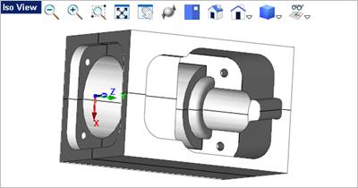
153 #6: Model a Connector Block Congratulations!!! You completed the exercise!! 17. Save the file as Connector_Block_Completed.vcp. 152


154 153 VisualCAD 2018 Exercise Guide #7: Model a Daisy Decor In this fun exercise you will use solid (or mesh) spheres, non-uniform scaling, polar arrays, sectioning and offsetting to produce this simplistic decorative design. The offset curves and rectangle are used during machining as containment and stock definition. Model a Daisy Decor What you will learn: In this exercise you will perform the following VisualCAD tasks: Create new Layers. 2. Model & Scale the Body. 3. Model & Scale the Pedal. 4. Ghosted Display Mode. 5. Polar Array the Pedal. 6. Additional Spheres Accents. 7. Create & Trim Section Curves. 8. Create Offset Curves. 9. Create the Stock Boundary. Create new Layers Create new Layers In this step you will use the Layer Manager to create some new layers and then set the active layer. 1. Display the Layer Manager. You can pick the Layer Manager icon on the Status Bar. 2. From the Layer Manager select the Add Layer icon located to add a new layer.

155 #7: Model a Daisy Decor Now lets rename the new layer to Curves. First double-left-click in the Name field to activate it, and enter Curves as the new layer name. 4. Repeat the procedure to create a new layer, this time named Sections. 5. Now repeat the procedure again, this time named Stock. 6. Now let's change the color of a couple of the new layers. In the Color field leftclick on the color box for the layer named Curves. This will display the Colors dialog. 7. Accept the default color Black and then pick OK to close the dialog.
156 155 VisualCAD 2018 Exercise Guide 8. If the Layer Manager keeps Auto-Hiding to the left side of the display, select the Auto Hide pin icon at the top of the Layer Manager. You can also see that the layer named Curves was changed to color black. 9. Now let's change the color of another layer. In the Color field left-click on the color box for the layer named Stock. Again, this will display the Colors dialog. 10. This time select the Blue color and then pick OK to close the dialog. You can use different color if you wish. If you have Auto Hide pinned, the Layer Manager will stay displayed.

157 #7: Model a Daisy Decor This time let's set the Active Layer. In the Active column, check the box for the layer named Default. and then unpin the Layer Manager to close it. 8.2 Model & Scale the Body Model & Scale the Body In this step you will model the center body using a solid sphere and non-uniform scaling. Note: You can replace the Solid commands with Mesh commands if desired. 1. Activate the Top View 2. Select the Solid Modeling tab by selecting anywhere in the viewport. tab from the top Ribbon Bar.


158 157 VisualCAD 2018 Exercise Guide 3. Now select the Sphere command. 4. In the Status Bar make sure the Grid Snap is On 5. For the center point select the grid point at (0,0,0) or just enter the coordinates 0,0,0 in command input bar.. 6. For the sphere radius, enter 3,0,0 corresponding grid point and press <Enter>. or select the 7. Select the solid sphere you just created. 8. You see the Modify / Transform tab appear on the right end of the Ribbon Bar. It ONLY appears when an entity is selected. Select the Transform tab.
159 #7: Model a Daisy Decor 9. Select the Scale 158 command. 10. From the Scale Selected Objects dialog, select the Non-Uniform Scaling option. 11. Set the X Length to 6, Y Length to 6 and the Z Length to Pick OK and the sphere is scaled as shown below. 13. Now press <Enter> to accept the modification. 14. Let's move the scaled sphere up to the origin. First make sure the Graphic Manipulator is On. The icon is located on the Status Bar. 15. Now select the sphere. 16. Select the Blue Z arrow to display the input field, enter 2.0 and press <Enter>. The sphere will move up in the positive Z Axis to the 0,0,0 origin as shown below.


160 159 VisualCAD 2018 Exercise Guide 17. Press <Enter> again to accept the move. 8.3 Model & Scale the Pedal Model & Scale the outer Pedal In this step you will model and scale one of the outer pedals, again using a solid sphere and non-uniform scaling. Note: You can replace the Solid commands with Mesh commands if desired. 1. Activate the Top View 2. Form the Solid Modeling command. 3. In the Status Bar make sure the Grid Snap is On 4. For the center point select the grid point at (0,6,0) or just enter the coordinates 0,6,0 in command input bar tab by selecting anywhere in the viewport. tab select the Sphere. and press <Enter>.


161 #7: Model a Daisy Decor For the sphere radius, enter 4.5 in the command input window and press <Enter> or select the grid point located at 0,1.5,0. Here is what you part should look like from the Front View: 6. From Iso View 1, select the solid sphere you just created.

162 161 VisualCAD 2018 Exercise Guide 7. Select the Transform tab from the ribbon bar. 8. Select the Scale 9. From the Scale Selected Objects dialog, select the Non-Uniform Scaling option. command. 10. Set the X Length to 2, Y Length to 9 and the Z Length to Pick OK and the sphere is scaled as shown below. 12. Now press the <Enter> key to accept the modification. 13. Let's move the scaled sphere into position along the Y Axis. First make sure the Graphic Manipulator is On. The icon is located on the Status Bar. 14. From the Front View, select the Red X arrow to display the input field, enter 3.5 and press <Enter>.


163 #7: Model a Daisy Decor Press <Enter> again to confirm the move and the sphere will move up to the Z 0 location as shown below. 16. Now select the sphere again. 17. Select the Blue Z arrow to display the input field, enter 3.5 and press <Enter>. 18. Press <Enter> again to confirm the move and the sphere will move to the X 0 location. If you activate the Right View image below. 8.4 your part should look like the Ghosted Display Mode Change the Top View to Ghosted Display For spheres drawn from the top view, it is best viewed using the ghosted display. 1. Activate the Top View tab by selecting anywhere in the viewport.

164 163 VisualCAD 2018 Exercise Guide 2. Select the View menu from the View Toolbar and then select Ghosted Display. Note: The View Toolbar will only display in the active viewport. The display should now look like this: 8.5 Polar Array the Pedal Create the Polar Array In this step you will create a polar array of the pedal sphere we just created. 1. Activate the Top View tab by selecting anywhere in the viewport. 2. Select the solid sphere pedal you just created in the previous step.

165 #7: Model a Daisy Decor 3. Select the Transform 4. Select the Polar Array objects dialog will display. 164 tab from the ribbon bar. command. The Polar array selected
166 165 VisualCAD 2018 Exercise Guide 5. In the Number of Objects field, enter The remaining options in the dialog should use the default values shown in the dialog above. 7. Pick OK from the dialog to create and preview the polar array. 8. Press <Enter> to accept the polar array. Your drawing should look like the images below. If not, select the Undo the previous steps. command and go back and repeat


167 #7: Model a Daisy Decor Additional Spheres Create the 4 additional Spheres In this step you will create the four spheres located in the outer corners of the design. Note: You can replace the Solid commands with Mesh commands if desired. 1. Activate the Top View 2. Form the Solid Modeling command. 3. In the Status Bar make sure the Grid Snap is On 4. For the center point select the grid point at (-8,-8,0) or just enter the coordinates -8,-8,0 in command input bar tab by selecting anywhere in the viewport. tab select the Sphere. and press <Enter>.


168 167 VisualCAD 2018 Exercise Guide 5. For the sphere radius, enter 1.0 in the command input bar and press <Enter> or select the grid point located at -8,-8,0 shown below. 6. Press <Enter> to repeat the Solid Sphere 7. Create the three additional spheres located at the coordinates shown in the illustration below. command. Your drawing should look like this:

169 #7: Model a Daisy Decor Create & Trim Section Curves Create Section Curves In this step we will create section curves that lie on the XY plane. Section curves are useful for creating offset boundaries which in turn can be used for toolpath containment. 1. Open the Layer Manager and set the Active Layer to Sections. Refer to the previous steps for displaying and using the Layer Manager. 2. Section curve are created in the plane of the active layer. We want the section curves to be generated on the XY plane so activate the Top View by selecting anywhere in the viewport. 3. Form the Curve Modeling tab select the Section Curve command. The Create section curves dialog will display. tab


170 169 VisualCAD 2018 Exercise Guide 4. If you move the slider you will see dynamically where the section curves lie. In this case, with the Top View active, moving the slider will display section curves dynamically in the XY plane and in the Z Axis. 5. We want to precisely locate the section plane so select the Pick point on model button from the dialog. 6. Then in the Front View pick the Z 0 grid point or simply enter 0,0,0 in the command input bar and press <Enter>. The section curves will be created and displayed in all four viewports.


171 #7: Model a Daisy Decor Open the Layer Manager and set the Active Layer to Sections. Refer to the previous steps for displaying and using the Layer Manager. In the following steps we will trim our section curves and merge them. 8. From the Top View, scroll to zoom in on the center where the section curves from the body and the pedals overlap each other. 9. From the Curve Modeling tab, select the Trim 10. Pick on the curve where you want it to be trimmed away. command.


172 171 VisualCAD 2018 Exercise Guide 11. Press the <Enter> to repeat the Trim location to trim. command and then pick another 12. Repeat this procedure until all of the curves are trimmed as shown below. 13. Now scroll to zoom out to see all of the curves.


173 #7: Model a Daisy Decor Press <Ctrl+A> to select all of the curves. 15. Now from the Curve Modeling tab select the Merge Curves command. This will merge all of the curves into one curve. This makes it easier to work with. Only curves that are joined end to end will be merged. Separate curves such as those created from the section of the outer spheres will remain separate curves. 8.8 Create Offset Curves Create Offset Curves 1. In the following steps you will create Offset curves from your Section Curves. Creating offset curves will also aid you during machining. For example, if you do not want to rough the entire stock, you can use section, offset or any other curve boundaries to limit/contain your toolpaths.

174 173 VisualCAD 2018 Exercise Guide 2. Open the Layer Manager and set the Active Layer to Curves and then make all other layers hidden. Refer to the previous steps for displaying and using the Layer Manager. 3. Now, select the main section curve, then go to the Curve Modeling tab and select the Offset command. 4. From the Top View move the cursor towards the outside of the curve so that you see the offset direction indicator point toward the outside. DO NOT pick a point! 5. Now with the curve offset direction displayed enter 0.5 in the command input bar and press the <Enter> key. The curve will be offset toward the outside by 0.5 inches.


175 #7: Model a Daisy Decor Press the <Enter> key to repeat the Offset command. This time select the section curves from one of the outer spheres, drag the cursor to indicate the offset direction and press <Enter> again. The offset value will default to the last value entered. 7. Repeat the section curves. command to create offset curves for the other 3 remaining Create the Stock Boundary Create the Stock Boundary Rectangle In this step you will create a 24" x 24" rectangle around the part. This can be used later during machining to help define the stock dimensions.


176 175 VisualCAD 2018 Exercise Guide 1. Open the Layer Manager and set the Active Layer to Stock. Refer to the previous steps for displaying and using the Layer Manager. 2. Activate the Top View 3. Form the Curve Modeling command. 4. For the first corner of the rectangle, you can select the grid point shown below or tab by selecting anywhere in the viewport. tab select the Rectangle enter -12,-12,0 in the command input bar <Enter>. 5. For the second corner of the rectangle, you can select the grid point shown below or enter 12,12,0 in the command input bar <Enter>. 6. and press and press Save the file as Daisy_Decor_Completed.vcp. Congratulations, you have completed this exercise!
177 #8: Using Construction Planes 176 #8: Using Construction Planes In this exercise you will learn how to use Construction Planes (C-Planes) to navigate and add features and text to your 3D models. C-Planes are also critical in learning how to orient imported parts for machining. Thus learning how to orient C-Planes and how to orient parts with the use of C-planes is critical knowledge for all VisualCAD users. Using Construction Planes What you will learn: In this exercise you will perform the following VisualCAD tasks: Orient the C-Plane. 2. Draw on a Face. 3. Other C-Plane Options. 4. Orient the Part. Orient the C-Plane Orient the C-Plane In this step we'll show you how to orient the Construction Plane (C-Plane). 1. First if you have completed and save the part model from Exercise #5 Connector Block, open that part now. It is shown below:

178 177 VisualCAD 2018 Exercise Guide Connector Block 2. Now select the Modeling Aids tab. On the very right end of the ribbon bar you will find the C-Plane pane. 3. From the Modeling Aids tab select the C-Plane to 3D Face command. 4. The command prompt says: "Pick a flat area". Select the right side face of the part and you will see that the C-Plane snaps to that face. If the Grid is not visible, select Hid / Show Grid from the View Toolbar. It is best to have the Construction Plane Grid visible. This allows you to better keep track of where the C-Plane is located and oriented.
179 #8: Using Construction Planes You can now see that the C-Plane and the Grid is alined with the right side flat face of the part. You will notice that the C-Plane origin is position at the point on the flat face you selected. 6. You can now draw on the C-Plane (see Text on a Part Face for more information). From the Curve Modeling Circle on Point command. tab select the 7. For the center point, toggle on the Grid Object Snap and select the origin point or simply enter 0,0 in the command window and press <Enter>. 8. Now select a point on the diameter of the circle.

180 179 VisualCAD 2018 Exercise Guide 9. You can also move the C-Plane origin. From the Modeling Aids select the C-Plane Origin tab command. 10. The command prompt says: "Pick origin point or enter coordinates x,y and Z" Enable the End Point Snap from the Status Toolbar and then select the bottom right end point of the face. You will see that the C-Plane origin and the Grid is moved to this point. 11. If you need the X Axis of the C-Plane aligned horizontally across the bottom of the part you can select the Rotate C-Plane about Axis also located on the Modeling Aids command. It is tab.
181 #8: Using Construction Planes The command prompt says: "Enter axis to rotate about and angle to rotate by (eg: X,45)" We want to rotate the Z Axis 90 degrees so enter Z,90 in the command window and press <Enter>. 13. Now what if you want the view orientation aligned with the C-Plane? 14. Just right-click anywhere in the view to display the View pop-up menu and select the Align to C-Plane command. This menu contains many Viewport related commands.


182 181 VisualCAD 2018 Exercise Guide 15. With the C-Plane aligned with the active Viewport pay close attention to where the origin of the C-Plane is: 16. Now you may want to come back to the C-Plane later so let's save it. From the Modeling Aids tab select the Save C-Plane command. 17. In the C-Plane Name dialog enter a unique name for the active C-Plane and then pick OK. 18. The active C-Plane is now saved with the part file. 19. Now let's change the C-Plane back to the default top view. From the Modeling Aids tab select the View menu and select Top View.
183 #8: Using Construction Planes Here is an easier way to align the C-Plane to the face AND align the XY Axis of the C-Plane at the same time. From the Modeling Aids the C-Plane by 3 Points tab select command. 21. The first point selected will be the origin, so make sure the End Point Snap is toggled on. 22. Then select the bottom left corner end point of the right side face of the part. Note: Do Not pick until you see the "End" indicated at the cursor location. 23. For the X Axis point select the end point at the back end of the part on the right side face.
 we discussed different ways to orient the CPlane. In this step we'll show you how to draw on a selected part face.")
184 183 VisualCAD 2018 Exercise Guide 24. For the Y Axis point select the end point at the top of the part on the right side face. 9.2 Text on a Part Face Drawing on a Face In the last step (see Orient the C-Plane) we discussed different ways to orient the CPlane. In this step we'll show you how to draw on a selected part face. This will come in handy if you want to identify your 3D parts or for modifying them. 1. First if you have completed and save the part model from Exercise #5 Connector Block, open that part now. It is shown below:
185 #8: Using Construction Planes 184 Connector Block 2. Now select the Modeling Aids tab. On the very right end of the ribbon bar you will find the C-Plane pane. 3. From the Modeling Aids tab select the C-Plane by 3 Points command. 4. The first point selected will be the origin, so make sure the End Point Snap is toggled on. 5. Then select the bottom left corner end point of the right side face of the part. Note: Do Not pick until you see the "End" indicated at the cursor location.
186 185 VisualCAD 2018 Exercise Guide 6. For the X Axis point select the end point at the back end of the part on the right side face. 7. For the Y Axis point select the end point at the top of the part on the right side face.

187 #8: Using Construction Planes Now right-click anywhere in the view to display the Viewpoint pop-up menu and select the Align to C-Plane command. This menu contains the Viewport related commands.

188 187 VisualCAD 2018 Exercise Guide 9. If you want to simply label your part you can add dimension text that will lie on the C-Plane. See Drawing & Dimensioning for that exercise. 10. In this exercise we will create text curves that you can engrave with the 2-1/2 Engraving toolpath strategy, go to the Curve Modeling select the Create Text tab and command. 11. This will display the Text to Create dialog. 12. For engraving text you may want to use a single stroke font. From the Font drop-down menu select the text font named MecSoft_Font-1.


189 #8: Using Construction Planes 188 If you do not see the MecSoft Font, close VisualCAD and click here to Download the single stroke font. Unzip and copy the file MecSoft_Font_1.ttf to the C:\Windows\Fonts folder. 13. The text preview will now look like this.

190 189 VisualCAD 2018 Exercise Guide 14. Make the following adjustments to the dialog: Allow Single Line Font: Checked Text Size: Now place in the Type in Text to Create window, replace the text VisualCAD with the following text: Part Number: The dialog should look like this: 17. Now pick the Done button. The dialog will close and command prompt says: Enter start point of text. 18. You will see the text as you move the cursor around the Viewport. 19. Enable the Grid Snap and then select the grid point to position the text, or 0.5,2.5 in the command window text should appear like this: and press <Enter>. The
.")

191 #8: Using Construction Planes 190 The text is actually individual curves that you can select as Control Geometry in your machining operations. 20. To select the curves, first make sure that the option Use Preselection Highlight is unchecked. It is located on the System section of the Options dialog (Home tab > Options > System). This was covered in the Set System Options section of Exercise # Now select one of the curves in the text or window select all of the curves in the text and then pick the Properties icon from the Status Bar to display the Properties dialog. 22. You will see that the text is actually 26 individual objects. 9.3 Other C-Plane Commands Other C-Plane Commands Be sure review the other C-Plane commands listed below. 1. Select the Modeling Aids 2. The C-Plane command pane is located on the right side of the ribbon bar: tab.
192 191 VisualCAD 2018 Exercise Guide Icon Command Immediately sets the orientation of the C-Plane to be parallel to the plane of the currently active view. The origin remains the same. Moves the origin of the C-Plane to a selected point or entered coordinates. The current configuration of the construction plane is saved whenever the model is saved. Moves the elevation of the C-Plane along its normal (perpendicular to the plane). Input is a single distance and may be positive or negative. A positive number moves the plane towards the positive end of the coordinate axes even if the viewing location is along the negative axis. All input values are treated as an incremental distance relative to the current location of the plane. Rotates the C-Plane about one of the principle axes of the current C-Plane, X, Y, or Z. The center of rotation is the center of the plane and not necessarily the origin. Input is 'axis,degrees'. Three points are selected (origin, x-axis and y-axis) or entered to re-orient the C-Plane. The y-axis point defines the C-Plane and the general direction of the positive y-axis. The C-Plane will be oriented to a selected flat plane of a geometry object. The pick point will become the C-Plane origin. Two points are entered to re-orient the x-axis of the C-Plane: Resets the C-Plane back to its default orientation relative to the WCS and the currently active viewport. The origin will be the WCS origin. This option saves the C-Plane orientation from the currently active view. A name must be provided for later reference when loading.


193 #8: Using Construction Planes 192 This option allows the retrieval of a saved C-Plane into the currently active view. A list of previously saved C-Planes is presented. These saved C-Planes may also be deleted in this option or renamed. 9.4 Orient the Part Orient the Part There may be times when you need to re-orient the part. This can happen at times when a part that you import into VisualCAD has it's WCS position skewed. In order to work with the part it has be oriented. We have deliberately skewed the part from Exercise #5 Connector Block so that it no longer lies parallel to any view. Here is what it looks like: 1. The first step toward to orienting this part is to define the C-Plane. For more about this see the topics Orient the C-Plane and Text on a Part Face in this exercise. 2. First make sure the Grid is visible. You can toggle the Grid on/off by selecting Hide / Show Grid from the View Toolbar. 3. Now activate the view that allows you to see the planar face that you want to use to orient the part by. In this example it is Iso View 1.


194 193 VisualCAD 2018 Exercise Guide 4. Go to the Modeling Aids tab and select the C-Plane by 3 Points command. 5. Activate the End Point Snap from the Status Toolbar and select the end points in the order shown below: The C-Plane will orient to the 3 points selected. 6. Now right-click anywhere in the Viewport (do not select any geometry) and select Align to C-Plane. This will align Iso View 1 Plane. parallel to the C-

195 #8: Using Construction Planes 194 The C-Plane will align to the Viewport. 7. Now we can orient the part. Select the part and go to the Modify / Transform tab and select the Part Orient command. This will display the Orient entire part dialog. Pick the option to Set as current view direction.

196 195 VisualCAD 2018 Exercise Guide 9. Pick OK and the part appears to disappear from the Viewport. 10. Now pick the Fit View icon from the View Toolbar. The part will appear with the WCS oriented in/on the center of the face that we used to align the CPlane


197 #8: Using Construction Planes 11. Now activate the Top View View Toolbar. and pick the Fit View 196 icon from the 12. Repeat this for the Front View and the Right View. Remember that you have to activate the Viewport before the View Toolbar will display. Left-click anywhere within the Viewport to activate it.
. 14. However, the part is still not oriented like the original part as shown below.")

198 197 VisualCAD 2018 Exercise Guide 13. Activate Iso View 1 again and this time select the Iso View icon from the View Toolbar to orient this Viewport. Great! You have the part oriented orthographically (i.e., Top, Front, Right). 14. However, the part is still not oriented like the original part as shown below. You see that the length of the part was oriented along the Y Axis and the WCS was positioned at the center of the front view. Let's show you some additional commands to fix that. 15. Activate Iso View 1 Graphic Manipulator and then from the Status Toolbar, toggle the On. 16. Now select the part to see the Graphic Manipulator displayed.
199 #8: Using Construction Planes 17. Pick the Z Rotation arc of the Graphic Manipulator window, enter 90 and then press <Enter>. to display the input 18. Now you see the part is rotated so press <Enter> to accept the rotation. 198

200 199 VisualCAD 2018 Exercise Guide Great where almost there! To move the WCS to the original location which was centered on the front face of the part we need to create a point there to move from. 19. Zoom in on the front face of the part. 20. From the Curve Modeling point between two points 21. Activate the End Point Snap tab select the command Create mid. from the Status toolbar. 22. Select the two diagonal end points on the front face of the part as shown. 23. You can now toggle the Graphic Manipulator off. 24. With the point created, window select the entire part (and point) or simply press <Ctrl+A>. 25. From the Modify / Transform command. tab select the Move by mouse 26. The command prompt says: Pick from point or enter coordinates x,y and z. Make sure the End Point Snap is active from the Status Toolbar and select the point you just created.


201 #8: Using Construction Planes Now the command prompt says: Pick to point or enter coordinates x,y and z. In the command window enter 0,0,0 and then press <Enter>. You will see that the part moved to the WCS origin. Now press <Enter> again to accept the move. 28. Now the part is aligned correctly accept for the C-Plane. Previously the C-Plane was aligned to the XY plane of WCS. Here is a neat trick to fix that: 29. Activate the Top View.


202 201 VisualCAD 2018 Exercise Guide 30. Now double-left-click on the Top View display to one Viewport set to the Top View. 31. Now right-click on the Top View tab. This will change the tab and select Quad Viewport.


203 #8: Using Construction Planes You see that Iso View 1 inherited the C-Plane of the Top View because that was the active View when you selected Quad Viewport. 32. Save the file as Construction_Planes_Completed.vcp. Congratulations on completing this exercise! 202
3 AXIS STANDARD CAD. BobCAD-CAM Version 28 Training Workbook 3 Axis Standard CAD
 3 AXIS STANDARD CAD This tutorial explains how to create the CAD model for the Mill 3 Axis Standard demonstration file. The design process includes using the Shape Library and other wireframe functions
Inventor 201. Work Planes, Features & Constraints: Advanced part features and constraints
 Work Planes, Features & Constraints: 1. Select the Work Plane feature tool, move the cursor to the rim of the base so that inside and outside edges are highlighted and click once on the bottom rim of the
Lesson 1 Parametric Modeling Fundamentals
 1-1 Lesson 1 Parametric Modeling Fundamentals Create Simple Parametric Models. Understand the Basic Parametric Modeling Process. Create and Profile Rough Sketches. Understand the "Shape before size" approach.
3D Design with 123D Design
 3D Design with 123D Design Introduction: 3D Design involves thinking and creating in 3 dimensions. x, y and z axis Working with 123D Design 123D Design is a 3D design software package from Autodesk. A
Spring 2011 Workshop ESSENTIALS OF 3D MODELING IN RHINOCEROS February 10 th 2011 S.R. Crown Hall Lower Core Computer Lab
 [1] Open Rhinoceros. PART 1 INTRODUCTION [4] Click and hold on the Boundary Lines in where they form a crossing and Drag from TOP RIGHT to BOTTOM LEFT to enable only the PERSPECTIVE VIEW. [2] When the
Autodesk Inventor Design Exercise 2: F1 Team Challenge Car Developed by Tim Varner Synergis Technologies
 Autodesk Inventor Design Exercise 2: F1 Team Challenge Car Developed by Tim Varner Synergis Technologies Tim Varner - 2004 The Inventor User Interface Command Panel Lists the commands that are currently
S206E Lecture 3, 5/15/2017, Rhino 2D drawing an overview
 Copyright 2017, Chiu-Shui Chan. All Rights Reserved. S206E057 Spring 2017 Rhino 2D drawing is very much the same as it is developed in AutoCAD. There are a lot of similarities in interface and in executing
Modeling a Gear Standard Tools, Surface Tools Solid Tool View, Trackball, Show-Hide Snaps Window 1-1
 Modeling a Gear This tutorial describes how to create a toothed gear. It combines using wireframe, solid, and surface modeling together to create a part. The model was created in standard units. To begin,
The Rectangular Problem
 C h a p t e r 2 The Rectangular Problem In this chapter, you will cover the following to World Class standards: The tools for simple 2D Computer Aided Drafting (CAD) The Command Line and the Tray The Line
NURBS modeling for Windows. Training Manual Level 1
 NURBS modeling for Windows Training Manual Level 1 Rhino Level 1 Training 2nd Ed.doc Robert McNeel & Associates 1997-2000 All Rights Reserved. Printed in U.S.A. Copyright by Robert McNeel & Associates.
StickFont Editor v1.01 User Manual. Copyright 2012 NCPlot Software LLC
 StickFont Editor v1.01 User Manual Copyright 2012 NCPlot Software LLC StickFont Editor Manual Table of Contents Welcome... 1 Registering StickFont Editor... 3 Getting Started... 5 Getting Started...
Chapter 2 Parametric Modeling Fundamentals
 2-1 Chapter 2 Parametric Modeling Fundamentals Create Simple Extruded Solid Models Understand the Basic Parametric Modeling Procedure Create 2-D Sketches Understand the Shape before Size Approach Use the
SOLIDWORKS 2016 and Engineering Graphics
 SOLIDWORKS 2016 and Engineering Graphics An Integrated Approach Randy H. Shih SDC PUBLICATIONS Better Textbooks. Lower Prices. www.sdcpublications.com Powered by TCPDF (www.tcpdf.org) Visit the following
Tutorial Second Level
 AutoCAD 2018 Tutorial Second Level 3D Modeling Randy H. Shih SDC PUBLICATIONS Better Textbooks. Lower Prices. www.sdcpublications.com Powered by TCPDF (www.tcpdf.org) Visit the following websites to learn
Autodesk Inventor - Basics Tutorial Exercise 1
 Autodesk Inventor - Basics Tutorial Exercise 1 Launch Inventor Professional 2015 1. Start a New part. Depending on how Inventor was installed, using this icon may get you an Inch or Metric file. To be
VERO UK TRAINING MATERIAL
 VERO UK TRAINING MATERIAL VISI Basic 2-D Modelling course (V-16) VISI Modelling 2D Design Introduction Many component designs follow a similar route, beginning with a 2D design, part modelled using solids
Rhinoceros NURBS modeling for Windows. Version 1.0 Training Manual Level 1
 Rhinoceros NURBS modeling for Windows Version 1.0 Training Manual Level 1 rhinolevel 1.doc Robert McNeel & Associates 1997. All Rights Reserved. Printed in U.S.A. Copyright by Robert McNeel & Associates.
Tutorial 3: Constructive Editing (2D-CAD)
") (2D-CAD) The editing done up to now is not much different from the normal drawing board techniques. This section deals with commands to copy items we have already drawn, to move them and to make multiple
(2D-CAD) The editing done up to now is not much different from the normal drawing board techniques. This section deals with commands to copy items we have already drawn, to move them and to make multiple
SolidWorks 2013 and Engineering Graphics
 SolidWorks 2013 and Engineering Graphics An Integrated Approach Randy H. Shih SDC PUBLICATIONS Schroff Development Corporation Better Textbooks. Lower Prices. www.sdcpublications.com Visit the following
Introduction to SolidWorks Basics Materials Tech. Wood
 Introduction to SolidWorks Basics Materials Tech. Wood Table of Contents Table of Contents... 1 Book End... 2 Introduction... 2 Learning Intentions... 2 Modelling the Base... 3 Modelling the Front... 10
Parametric Modeling with. Autodesk Fusion 360. First Edition. Randy H. Shih SDC. Better Textbooks. Lower Prices.
 Parametric Modeling with Autodesk Fusion 360 First Edition Randy H. Shih SDC PUBLICATIONS Better Textbooks. Lower Prices. www.sdcpublications.com Powered by TCPDF (www.tcpdf.org) Visit the following websites
Autodesk Fusion 360 Training: The Future of Making Things Attendee Guide
 Autodesk Fusion 360 Training: The Future of Making Things Attendee Guide Abstract After completing this workshop, you will have a basic understanding of editing 3D models using Autodesk Fusion 360 TM to
Module 1: Basics of Solids Modeling with SolidWorks
 Module 1: Basics of Solids Modeling with SolidWorks Introduction SolidWorks is the state of the art in computer-aided design (CAD). SolidWorks represents an object in a virtual environment just as it exists
COMPUTER AIDED ARCHITECTURAL GRAPHICS FFD 201/Fall 2013 HAND OUT 1 : INTRODUCTION TO 3D
 COMPUTER AIDED ARCHITECTURAL GRAPHICS FFD 201/Fall 2013 INSTRUCTORS E-MAIL ADDRESS OFFICE HOURS Özgür Genca ozgurgenca@gmail.com part time Tuba Doğu tubadogu@gmail.com part time Şebnem Yanç Demirkan sebnem.demirkan@gmail.com
Autodesk Fusion 360: Model. Overview. Modeling techniques in Fusion 360
 Overview Modeling techniques in Fusion 360 Modeling in Fusion 360 is quite a different experience from how you would model in conventional history-based CAD software. Some users have expressed that it
Parametric Modeling with UGS NX 4
 Parametric Modeling with UGS NX 4 Randy H. Shih Oregon Institute of Technology SDC PUBLICATIONS Schroff Development Corporation www.schroff.com www.schroff-europe.com 2-1 Chapter 2 Parametric Modeling
Jewelry Box Lid. A. Sketch Lid Circle. Step 1. If necessary start a new Mastercam file, click FILE Menu > New. Fig. 3
 Mastercam X9 Chapter 39 Jewelry Box Lid A. Sketch Lid Circle. Step 1. If necessary start a new Mastercam file, click FILE Menu > New. Step 2. Click CREATE Menu > Arc > Circle Center Point. Step 3. Key-in
Autodesk Inventor 2019 and Engineering Graphics
 Autodesk Inventor 2019 and Engineering Graphics An Integrated Approach Randy H. Shih SDC PUBLICATIONS Better Textbooks. Lower Prices. www.sdcpublications.com Powered by TCPDF (www.tcpdf.org) Visit the
Chapter 2 Parametric Modeling Fundamentals
 2-1 Chapter 2 Parametric Modeling Fundamentals Create Simple Extruded Solid Models Understand the Basic Parametric Modeling Procedure Create 2-D Sketches Understand the "Shape before Size" Approach Use
Revit Architecture 2015 Basics
 Revit Architecture 2015 Basics From the Ground Up Elise Moss Authorized Author SDC P U B L I C AT I O N S Better Textbooks. Lower Prices. www.sdcpublications.com Powered by TCPDF (www.tcpdf.org) Visit
Parametric Modeling. With. Autodesk Inventor. Randy H. Shih. Oregon Institute of Technology SDC PUBLICATIONS
 Parametric Modeling With Autodesk Inventor R10 Randy H. Shih Oregon Institute of Technology SDC PUBLICATIONS Schroff Development Corporation www.schroff.com www.schroff-europe.com 2-1 Chapter 2 Parametric
SOLIDWORKS: Lesson III Patterns & Mirrors. UCF Engineering
 SOLIDWORKS: Lesson III Patterns & Mirrors UCF Engineering Solidworks Review Last lesson we discussed several more features that can be added to models in order to increase their complexity. We are now
SOLIDWORKS 2016: A Power Guide for Beginners and Intermediate Users
 SOLIDWORKS 2016: A Power Guide for Beginners and Intermediate Users The premium provider of learning products and solutions www.cadartifex.com Table of Contents Dedication... 3 Preface... 15 Part 1. Introducing
QuickTutor. An Introductory SilverScreen Modeling Tutorial. Solid Modeler
 QuickTutor An Introductory SilverScreen Modeling Tutorial Solid Modeler TM Copyright Copyright 2005 by Schroff Development Corporation, Shawnee-Mission, Kansas, United States of America. All rights reserved.
TRAINING GUIDE LATHE-LESSON-1 FACE, ROUGH, FINISH AND CUTOFF
 TRAINING GUIDE LATHE-LESSON-1 FACE, ROUGH, FINISH AND CUTOFF Mastercam Training Guide Objectives You will create the geometry for Lathe-Lesson-1, and then generate a toolpath to machine the part on a CNC
SolidWorks Implementation Guides. User Interface
 SolidWorks Implementation Guides User Interface Since most 2D CAD and SolidWorks are applications in the Microsoft Windows environment, tool buttons, toolbars, and the general appearance of the windows
Solid Problem Ten. In this chapter, you will learn the following to World Class standards:
 C h a p t e r 11 Solid Problem Ten In this chapter, you will learn the following to World Class standards: 1. Sketch of Solid Problem Ten 2. Starting a 3D Part Drawing 3. Modifying How the UCS Icon is
SolidWorks Intro Part 1b
 SolidWorks Intro Part 1b Dave Touretzky and Susan Finger 1. Create a new part We ll create a CAD model of the 2 ½ D key fob below to make on the laser cutter. Select File New Templates IPSpart If the SolidWorks
TRAINING GUIDE. Sample not. for Distribution LATHE-LESSON-1 FACE, ROUGH, FINISH AND CUTOFF
 TRAINING GUIDE LATHE-LESSON-1 FACE, ROUGH, FINISH AND CUTOFF Mastercam Training Guide Objectives You will create the geometry for Lathe-Lesson-1, and then generate a toolpath to machine the part on a CNC
Parametric Modeling with NX 12
 Parametric Modeling with NX 12 NEW Contains a new chapter on 3D printing Randy H. Shih SDC PUBLICATIONS Better Textbooks. Lower Prices. www.sdcpublications.com Powered by TCPDF (www.tcpdf.org) Visit the
LAB # 2 3D Modeling, Properties Commands & Attributes
 COMSATS Institute of Information Technology Electrical Engineering Department (Islamabad Campus) LAB # 2 3D Modeling, Properties Commands & Attributes Designed by Syed Muzahir Abbas 1 1. Overview of the
TRAINING GUIDE. Sample. Distribution. not for LATHE-LESSON-1 FACE, ROUGH, FINISH AND CUTOFF
 TRAINING GUIDE LATHE-LESSON-1 FACE, ROUGH, FINISH AND CUTOFF Mastercam Training Guide Objectives You will create the geometry for Lathe-Lesson-1, and then generate a toolpath to machine the part on a CNC
Basic Modeling 1 Tekla Structures 12.0 Basic Training September 19, 2006
 Tekla Structures 12.0 Basic Training September 19, 2006 Copyright 2006 Tekla Corporation Contents Contents 3 1 5 1.1 Start Tekla Structures 6 1.2 Create a New Model BasicModel1 7 1.3 Create Grids 10 1.4
4) Finish the spline here. To complete the spline, double click the last point or select the spline tool again.
 Finish the spline here. To complete the spline, double click the last point or select the spline tool again.") 1) Select the line tool 3) Move the cursor along the X direction (be careful to stay on the X axis alignment so that the line is perpendicular) and click for the second point of the line. Type 0.5 for
1) Select the line tool 3) Move the cursor along the X direction (be careful to stay on the X axis alignment so that the line is perpendicular) and click for the second point of the line. Type 0.5 for
SolidWorks 2½D Parts
 SolidWorks 2½D Parts IDeATe Laser Micro Part 1b Dave Touretzky and Susan Finger 1. Create a new part In this lab, you ll create a CAD model of the 2 ½ D key fob below to make on the laser cutter. Select
MFG12197 FeatureCAM Hands On Milling, turning and mill turn with Feature Based Machining
 MFG12197 FeatureCAM Hands On Milling, turning and mill turn with Feature Based Machining Jeremy Malan Delcam Learning Objectives Learn how to instantly machine parts once their features are defined Learn
solidthinking Environment...1 Modeling Views...5 Console...13 Selecting Objects...15 Working Modes...19 World Browser...25 Construction Tree...
 Copyright 1993-2009 solidthinking, Inc. All rights reserved. solidthinking and renderthinking are trademarks of solidthinking, Inc. All other trademarks or service marks are the property of their respective
Feature-based CAM software for mills, multi-tasking lathes and wire EDM. Getting Started
 Feature-based CAM software for mills, multi-tasking lathes and wire EDM www.featurecam.com Getting Started FeatureCAM 2015 R3 Getting Started FeatureCAM Copyright 1995-2015 Delcam Ltd. All rights reserved.
Chapter 12: Pull Toy - Solids and Transforms
 This tutorial demonstrates using solid primitives and simple transforms. You will learn how to: Enter coordinates to place points exactly. Draw a free-form curve and polygon. Create a pipe along a curve.
Solidworks 2006 Surface-modeling
 Solidworks 2006 Surface-modeling (Tutorial 2-Mouse) Surface-modeling Solid-modeling A- 1 Assembly Design Design with a Master Model Surface-modeling Tutorial 2A Import 2D outline drawing into Solidworks2006
Introduction to SolidWorks for Technology. No1: Childs Toy
 Introduction to SolidWorks for Technology No1: Childs Toy Table of Contents Table of Contents... 1 Introduction... 2 Part Modelling: Cab... 3 Part Modelling: Base... 6 Part Modelling: Wheel... 12 Assembly:
Doctor Walt s Solid Edge Version 19 Workbook 137
 Still using the SMART DIMENSION Tool, click on the left vertical edge of the sketch. Move the cursor to the left and click to set the text position. Type 1.5 for the value and hit the ENTER Key. Next,
COMPUTER AIDED DESIGN CURRICULLOM RHINO BASED 3D DESIGN
 COMPUTER AIDED DESIGN CURRICULLOM RHINO BASED 3D DESIGN S.no. CONTENTS Page no S. no. CONTENTS PAGE no. 1. Introduction 1 2. Necessary of Rhino in Designing 2 3. Working with 3D Models 3 4. Object Types
Alibre Design Tutorial - Simple Revolve Translucent Glass Lamp Globe
 Alibre Design Tutorial - Simple Revolve Translucent Glass Lamp Globe Part Tutorial Exercise 2: Globe-1 In this Exercise, We will set System Parameters first. Then, in sketch mode, we will first Outline
Module 5: Creating Sheet Metal Transition Piece Between a Square Tube and a Rectangular Tube with Triangulation
 1 Module 5: Creating Sheet Metal Transition Piece Between a Square Tube and a Rectangular Tube with Triangulation In Module 5, we will learn how to create a 3D folded model of a sheet metal transition
Module 1B: Parallel-Line Flat Pattern Development of Sheet- Metal Folded Model Wrapping the 3D Space of A Truncated Right Prism
 Inventor (5) Module 1B: 1B- 1 Module 1B: Parallel-Line Flat Pattern Development of Sheet- Metal Folded Model Wrapping the 3D Space of A Truncated Right Prism In this Module, we will learn how to create
Structural & Thermal Analysis Using the ANSYS Workbench Release 12.1 Environment
 ANSYS Workbench Tutorial Structural & Thermal Analysis Using the ANSYS Workbench Release 12.1 Environment Kent L. Lawrence Mechanical and Aerospace Engineering University of Texas at Arlington SDC PUBLICATIONS
TOOLPATHS TRAINING GUIDE. Sample. Distribution. not for MILL-LESSON-4-TOOLPATHS DRILL AND CONTOUR
 TOOLPATHS TRAINING GUIDE MILL-LESSON-4-TOOLPATHS DRILL AND CONTOUR Mill-Lesson-4 Objectives You will generate a toolpath to machine the part on a CNC vertical milling machine. This lesson covers the following
GETTING STARTED WITH MASTERCAM SOLIDS
 GETTING STARTED WITH MASTERCAM SOLIDS June 2017 GETTING STARTED WITH MASTERCAM SOLIDS June 2017 2017 CNC Software, Inc. All rights reserved. Software: Mastercam 2018 Terms of Use Use of this document is
Create a Rubber Duck. This tutorial shows you how to. Create simple surfaces. Rebuild a surface. Edit surface control points. Draw and project curves
 Page 1 of 24 Create a Rubber Duck This exercise focuses on the free form, squishy aspect. Unlike the flashlight model, the exact size and placement of the objects is not critical. The overall form is the
Module 4A: Creating the 3D Model of Right and Oblique Pyramids
 Inventor (5) Module 4A: 4A- 1 Module 4A: Creating the 3D Model of Right and Oblique Pyramids In Module 4A, we will learn how to create 3D solid models of right-axis and oblique-axis pyramid (regular or
VisualMILL Getting Started Guide
 VisualMILL Getting Started Guide Welcome to VisualMILL Getting Started Guide... 4 About this Guide... 4 Where to go for more help... 4 Tutorial 1: Machining a Gasket... 5 Introduction... 6 Preparing the
Getting Started with Mastercam Solids. March 2016
 Getting Started with Mastercam Solids March 2016 Mastercam 2017 Solids Getting Started TERMS OF USE Date: March 2016 Copyright 2016 CNC Software, Inc. All rights reserved. Software: Mastercam 2017 Use
Rhinoceros NURBS modeling for Windows. Training Manual Level 1
 Rhinoceros NURBS modeling for Windows Training Manual Level 1 R30TML1-08-2005 Rhinoceros Level 1 Training Manual v3.0 Robert McNeel & Associates 2005 All Rights Reserved. Printed in U.S.A. Copyright by
TUTORIAL 2. OBJECTIVE: Use SolidWorks/COSMOS to model and analyze a cattle gate bracket that is subjected to a force of 100,000 lbs.
 TUTORIAL 2 OBJECTIVE: Use SolidWorks/COSMOS to model and analyze a cattle gate bracket that is subjected to a force of 100,000 lbs. GETTING STARTED: 1. Open the SolidWorks program. 2. Open a new part file.
The Department of Construction Management and Civil Engineering Technology CMCE-1110 Construction Drawings 1 Lecture Introduction to AutoCAD What is
 The Department of Construction Management and Civil Engineering Technology CMCE-1110 Construction Drawings 1 Lecture Introduction to AutoCAD What is AutoCAD? The term CAD (Computer Aided Design /Drafting)
Autodesk Inventor 2016 Learn by doing. Tutorial Books
 Autodesk Inventor 2016 Learn by doing Tutorial Books Copyright 2015 Kishore This book may not be duplicated in any way without the express written consent of the publisher, except in the form of brief
ME009 Engineering Graphics and Design CAD 1. 1 Create a new part. Click. New Bar. 2 Click the Tutorial tab. 3 Select the Part icon. 4 Click OK.
 PART A Reference: SolidWorks CAD Student Guide 2014 2 Lesson 2: Basic Functionality Active Learning Exercises Creating a Basic Part Use SolidWorks to create the box shown at the right. The step-by-step
Acknowledgement INTRODUCTION
 Submitted by: 1 Acknowledgement INTRODUCTION Computers are increasingly being used for doing engineering drawings and graphics work because computers allow the graphics designer or the draughtsman to change
An Introduction to Autodesk Inventor 2010 and AutoCAD Randy H. Shih SDC PUBLICATIONS. Schroff Development Corporation
 An Introduction to Autodesk Inventor 2010 and AutoCAD 2010 Randy H. Shih SDC PUBLICATIONS Schroff Development Corporation www.schroff.com 2-1 Chapter 2 Parametric Modeling Fundamentals Create Simple Extruded
TRAINING SESSION Q2 2016
 There are 8 main topics in this training session which focus on the Sketch tools in IRONCAD. Content Sketch... 2 3D Scene Background Settings... 3 Creating a new empty Sketch... 4 Foam with cut out for
Visual 2012 Help Index
 Visual 2012 Help Index Absolute Coordinates 2.1 Cartesian Coordinates Aim 7.4.3 Place and Aim Luminaires 7.4.4 Reaiming Luminaires Align Cursor and Plane to Current View 9.6 Align to View Align Cursor
TRAINING GUIDE MILL-LESSON-FBM-1 FBM MILL AND FBM DRILL
 TRAINING GUIDE MILL-LESSON-FBM-1 FBM MILL AND FBM DRILL Mastercam Training Guide Objectives Previously in Mill-Lesson-6 and Mill-Lesson-7 geometry was created and machined using standard Mastercam methods.
Lesson 5: Board Design Files
 5 Lesson 5: Board Design Files Learning Objectives In this lesson you will: Use the Mechanical Symbol Editor to create a mechanical board symbol Use the PCB Design Editor to create a master board design
EZ-Mill EXPRESS TUTORIAL 2. Release 13.0
 E-Mill EPRESS TUTORIAL 2 Release 13.0 Copyright Notice This manual describes software that contains published and unpublished works of authorship proprietary to ECAM Solutions, Inc. It is made available
An Introduction to Autodesk Inventor 2012 and AutoCAD Randy H. Shih SDC PUBLICATIONS. Schroff Development Corporation
 An Introduction to Autodesk Inventor 2012 and AutoCAD 2012 Randy H. Shih SDC PUBLICATIONS www.sdcpublications.com Schroff Development Corporation Visit the following websites to learn more about this book:
GDL Toolbox 2 Reference Manual
 Reference Manual Archi-data Ltd. Copyright 2002. New Features Reference Manual New Save GDL command Selected GDL Toolbox elements can be exported into simple GDL scripts. During the export process, the
Solid Modeling: Part 1
 Solid Modeling: Part 1 Basics of Revolving, Extruding, and Boolean Operations Revolving Exercise: Stepped Shaft Start AutoCAD and use the solid.dwt template file to create a new drawing. Create the top
Chapter 4 Feature Design Tree
 4-1 Chapter 4 Feature Design Tree Understand Feature Interactions Use the FeatureManager Design Tree Modify and Update Feature Dimensions Perform History-Based Part Modifications Change the Names of Created
Elise Moss Revit Architecture 2017 Basics From the Ground Up SDC. Better Textbooks. Lower Prices.
 Elise Moss Revit Architecture 2017 Basics From the Ground Up SDC P U B L I C AT I O N S Better Textbooks. Lower Prices. www.sdcpublications.com Powered by TCPDF (www.tcpdf.org) Visit the following websites
Tutorial 1 Engraved Brass Plate R
 Getting Started With Tutorial 1 Engraved Brass Plate R4-090123 Table of Contents What is V-Carving?... 2 What the software allows you to do... 3 What file formats can be used?... 3 Getting Help... 3 Overview
Rhinoceros NURBS modeling for Windows
 Rhinoceros NURBS modeling for Windows Training Manual Level 1 Version 4.0 R40TML5-17-2007 Rhinoceros Level 1 Training Manual v4.0 Robert McNeel & Associates 2006 All Rights Reserved. Printed in U.S.A.
Parametric Modeling. with. Autodesk Inventor Randy H. Shih. Oregon Institute of Technology SDC
 Parametric Modeling with Autodesk Inventor 2009 Randy H. Shih Oregon Institute of Technology SDC PUBLICATIONS Schroff Development Corporation www.schroff.com Better Textbooks. Lower Prices. 2-1 Chapter
QUICK-START TUTORIALS
 PUERMC02_0132276593.QXD 08/09/2006 06:05 PM Page 83 QUICK-START TUTORIALS Chapter Objectives Create two real 3D modeling projects, starting them from scratch. Know the difference between representing 3D
Structural & Thermal Analysis using the ANSYS Workbench Release 11.0 Environment. Kent L. Lawrence
 ANSYS Workbench Tutorial Structural & Thermal Analysis using the ANSYS Workbench Release 11.0 Environment Kent L. Lawrence Mechanical and Aerospace Engineering University of Texas at Arlington SDC PUBLICATIONS
Speedway. Body. (S) on the Sketch toolbar. Fig. 1
 on the Sketch toolbar. Fig. 1") Chapter 1 A. New Part. Step 1. Click File Menu > New. Speedway Body Step 2. Click Part from the list and click OK, Fig. 1. B. Sketch Construction Rectangle. Step 1. Click Right Plane in the Feature Manager
Chapter 1 A. New Part. Step 1. Click File Menu > New. Speedway Body Step 2. Click Part from the list and click OK, Fig. 1. B. Sketch Construction Rectangle. Step 1. Click Right Plane in the Feature Manager
Solid surface modeling in AutoCAD
 Solid surface modeling in AutoCAD Introduction into 3D modeling Managing views of 3D model Coordinate Systems 1 3D model advantages ability to view the whole model looking inside the model collision checking
3D Modeling and Design Glossary - Beginner
 3D Modeling and Design Glossary - Beginner Align: to place or arrange (things) in a straight line. To use the Align tool, select at least two objects by Shift left-clicking on them or by dragging a box
CATIA V5 Parametric Surface Modeling
 CATIA V5 Parametric Surface Modeling Version 5 Release 16 A- 1 Toolbars in A B A. Wireframe: Create 3D curves / lines/ points/ plane B. Surfaces: Create surfaces C. Operations: Join surfaces, Split & Trim
AutoCAD 2009 Tutorial
 AutoCAD 2009 Tutorial Second Level: 3D Modeling Randy H. Shih Oregon Institute of Technology SDC PUBLICATIONS Schroff Development Corporation www.schroff.com Better Textbooks. Lower Prices. AutoCAD 2009
Battery Holder. Chapter 9. Boat. A. Front Extrude. Step 1. Click File Menu > New, click Part and OK. SolidWorks 10 BATTERY HOLDER AA BOAT Page 9-1
 Chapter 9 Boat Battery Holder A. Front Extrude. Step 1. Click File Menu > New, click Part and OK. AA Step 2. Click Front (plane) in the Feature Manager and click Sketch from the Content toolbar, Fig. 1.
An Introduction to Autodesk Inventor 2013 and AutoCAD
 An Introduction to Autodesk Inventor 2013 and AutoCAD 2013 Randy H. Shih SDC PUBLICATIONS Schroff Development Corporation Better Textbooks. Lower Prices. www.sdcpublications.com Visit the following websites
Rhinoceros NURBS modeling for Windows
 Rhinoceros NURBS modeling for Windows Training Manual Level 1 Version 4.0 R40TML1 Oct-2008 Rhinoceros Level 1 Training Manual v4.0 Robert McNeel & Associates 2008 All Rights Reserved. Printed in U.S.A.
A Comprehensive Introduction to SolidWorks 2011
 A Comprehensive Introduction to SolidWorks 2011 Godfrey Onwubolu, Ph.D. SDC PUBLICATIONS www.sdcpublications.com Schroff Development Corporation Chapter 2 Geometric Construction Tools Objectives: When
1.1: Introduction to Fusion 360
 .: Introduction to Fusion 360 Fusion 360 is a cloud- based CAD/CAM tool for collaborative product development. The tools in Fusion enable exploration and iteration on product ideas and collaboration within
4. If you are prompted to enable hardware acceleration to improve performance, click
 Exercise 1a: Creating new points ArcGIS 10 Complexity: Beginner Data Requirement: ArcGIS Tutorial Data Setup About creating new points In this exercise, you will use an aerial photograph to create a new
Getting started with Solid Edge with Synchronous Technology
 Getting started with Solid Edge with Synchronous Technology Publication Number MU29000-ENG-1000 Proprietary and Restricted Rights Notice This software and related documentation are proprietary to Siemens
On the ribbon bar, click the Select from Sketch button.
 On the Features toolbar, click the Revolved Protrusion command. On the ribbon bar, click the Select from Sketch button. In the part window, select the Sketch, and on the ribbon bar click the Accept button.
GEO 154 CARTOGRAPHY II- PLOTTING USING AUTOCAD- ASSIGMENT HELP
 GEO 154 CARTOGRAPHY II- PLOTTING USING AUTOCAD- ASSIGMENT HELP DOCUMENT. For one to two reasons data may not be in a format that can be integrated into AutoCAD software, but coordinates may be separated
Mastercam X9 for SOLIDWORKS
 Chapter 21 CO2 Shell Car Mastercam X9 for SOLIDWORKS A. Enable Mastercam for SOLIDWORKS. Step 1. If necessary, turn on Mastercam for SOLIDWORKS, click the flyout of Options on the Standard toolbar and