Prof. Steven S. Saliterman Introductory Medical Device Prototyping
|
|
|
- Kristin Powell
- 5 years ago
- Views:
Transcription

1 Introductory Medical Device Prototyping Department of Biomedical Engineering, University of Minnesota


2 Images courtesy of Haas
3 You must complete safety instruction before using tools and equipment in the Medical Device Center, ME Student Shop and CSE Workshops. All machinery can be dangerous. You must have a trained individual instruct you first when using unfamiliar equipment. Only authorized and trained individuals may operate CNC equipment. Code examples shown are for illustration purposes only, and are not meant for operation or programming actual equipment. They may be incomplete or contain errors. Always abide by shop safety instructions and never engage in horseplay. Remember to wear OSHA approved eye protection in the shop, short sleeves, leather or steel toed shoes, and secure long hair, avoid loose clothing, and take off rings, watches and bracelets when using power equipment. These slides are part of the Introductory Medical Device Prototyping course at the University of Minnesota, and are not meant for any other purpose. Formal training in Haas is available from Productivity, Inc.

4 Image courtesy of Haas


5
6 X is the back to front motion, with the part X0 being coincident with the Z axis. Determines diameter. Z is the spindle axis, and the part Z0 is normally the front finished face. Determines location of faces, shoulders and grooves. Home reference position movement at startup to extreme limits. A zero-return at POWER/STARTUP. This is the machine zero. We use a floating zero referred to as the part zero or part origin. We touch off the face and diameter, and store the offset from the machine zero in X and Z register of the Tool Offsets Page. (Not the same as mill which uses G54!)
7 Image courtesy of Productivity and Haas
8 Normally most of the X values are going to be positive in a part program. A negative X will occur only if you face a part past the centerline. X values are in diameters (not radius), hence a X1.0 will be moving the machine along the x-axis 0.5 in the positive direction. Z values will tend to be negative since zero is at the face. (Max. -1 travel beyond the spindle zero.)
9 Absolute positioning: X and Z codes are based on the Zero point of the part. If a diameter of inches is needed, you input X If you are facing a shoulder 0.3 back from the face of the part, Z is input. Incremental positioning: U and W based on current position of the machine. So a change of U would be a smaller diameter of 0.5 from where the machine is presently at. A grooving tool moving back ¾ behind the previous groove would be input as W Also called point to point. Simultaneous moves are possible e.g. G01 X2.000 W-.25 Moves X in absolute and Z in incremental at the same time.
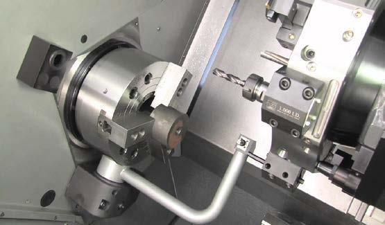
10 An optional Y-axis moves tools perpendicular to the spindle center line. This motion is achieved by compound motion of the X-axis and Y-axis ball screws. Image courtesy of Haas


11 Right Image courtesy of Haas

12 Display buttons Function buttons Jog buttons Mode buttons Cursor buttons Override buttons Number buttons Alpha buttons Image courtesy of Haas
13 Power On- Turns CNC machine on. All axis to machine zero X then Y. Power Off- Turns CNC machine tool off. Emergency Stop - Stops all axis motion, spindle, tool changer and coolant pump. Jog Handle-Jogs axis selected; scroll through programs, menu items while editing and also altering feeds and speeds. Cycle Start- Starts program in run mode or graphics mode. Feed Hold- Stops all axis motion. Spindle will continue to turn. Reset- Stops machine, will rewind program. Power Up/Restart- Axis will return to machine zero Recover- If a tool change is stopped in middle of a cycle an alarm will come up. Push the Recover button and follow the instructions to bring the tool change cycle to the beginning.

14 Watch 12m 1. Tool (selected)) and work offset tables 2. Spindle, position and active tool figure. 3. ZERO RET, HAND JOG key mode buttons active

15 1. Provides two program editing panes. 2. Allows program editing, management, and transfer functions. 3. EDIT, MDI/DNC, LIST PROG buttons active

16 1. Provides all control features necessary to make a part. 2. MEM button active
17
18 Jog Mode allows you to jog each of the axes to a desired location. Before jogging the axes it is necessary to home (beginning axes reference point) the axes. (ZERO/RET AND AUTO/ALL AXES OR HOME/G28) To enter jog mode press HANDLE JOG, then press the desired axis (e.g. X, Z, etc.) and either use the handle jog keys or the jog handle to move the axis. There are different increment speeds that can be used while in jog mode;.0001,.001,.01 and.1.
19 F1- F4 Keys Different action in Editing Program and Offset mode. X Dia Mesur (X Diameter Measure) Record X-axis tool shift offsets on the offset page during part setup. Next Tool Next tool from the turret (usually used during part setup). X/Z Toggle between X-axis and Z-axis jog modes during part setup. Z Face Measur ( Z Face Measure) Record Z-axis tool shift offsets on the offset page during part setup.
20 Chip FWD (Chip Auger Forward) - Move chips out of the machine. Chip Stop (Chip Auger Stop) - Stops auger movement. Chip REV (Chip Auger Reverse) - Starts the optional chip auger in the Reverse direction. X/-X and Z/-Z (axis keys) - Manually jog axis by holding down the individual key or pressing the desired axes and using the jog handle. Rapid - When pressed simultaneously with one of the above keys (X+, X-, Z+, Z-), that axis will move in the selected direction at maximum jog speed. <- TS Pressing this key moves the tailstock towards the spindle. TS Rapid Increases the speed of the tailstock when pressed simultaneously with one of the other tailstock keys. -> TS Pressing this key moves the tailstock away from the spindle. XZ (2-Axis) Jogging
21 10 - Decreases current feed rate by 10%. 100% - Sets control over ride feed rate to programmed feed rate Increases current feed rate by 10% Decreases current spindle speed by 10%. 100% - Sets overridden spindle speed to programmed speed Increases current spindle speed by 10%.

22 Manual offset entry: 1. Load a tool into the tool turret. 2. Press the HANDLE JOG key (A) 3. Press.1/100. (B) (The lathe will move at a fast rate when the handle is turned). 4. Toggle between the X and Z jog keys until the tool is touching the side of the part at about a 1/8 of an inch from the front edge. 5. Place a sheet of paper between the tool and the part. Carefully move the tool as close as possible while still able to move the paper. Images courtesy of Haas
23 6. Press OFFSET (C), until the Tool Geometry table is displayed. 7. Press X DIA MESUR (D). The control will then prompt for the diameter of the part. This will take the X position located in the bottom left of the screen and the diameter of the part and put it with the position of the tool. 8. Back the tool from the part and position the tool tip so that it is touching the face of the stock. 9. Press Z FACE MEAS (E). This will take the current Z position and write it to the tool offset. 10. The cursor will move to the Z-axis location for the tool. 11. Press NEXT TOOL (F).
24 Part Zero is a user defined reference point that the CNC control will use to program all moves from. Select Tool #1 by pressing MDI/DNC, enter T1 and press TURRET FWD. Jog X and Z until the tool is just touching the face of the part. Press Z FACE MEAS to set part zero. a

25 Watch 7 m Alternative to manually recording tool offsets. Each tool is touched-off on a probe. After that, only one tool is touched off on the part s zero position, and work offsets are automatically set for all tools. When the probe is down, axes can only be moved with handle jog. Once the probe is touched, the control will beep, the turret will halt, and the position of the tool will be stored typically in G54. Faster than manual method. Image courtesy of Haas
26 The probe is first set up for tooling in manual mode, where initial tool measurements are made. After this setup, automatic mode is available to reset offsets when inserts are changed. Tool break detection is also available to monitor tool wear and breakage. The software generates G code which can be inserted into lathe programs to enable probe use during automatic operation. First press MDI/DNC and then PRGRM CONVRS to access the IPS tabbed menu set. Use the right cursor key to navigate to the PROBE tab and press WRITE/ENTER.

27 Image courtesy of Haas

28 Image courtesy of Haas
29 1. Tools must be touched off in manual mode before automatic mode can be used. 2. Enter the probe menu by pressing MDI/DNC, then PRGRM CONVRS, and selecting the Probe tab. Press F1 to lower the probe arm. 3. Select the tool to be touched off using TURRET FWD or TURRET REV. 4. Select Op Mode Manual using the left / right cursor arrow keys, then press WRITE/ENTER or the down cursor arrow key. 5. The tool offset option is set according to the currently selected tool position. Press WRITE/ENTER or the down cursor arrow key. 6. Type the tool offset number to be used, then press WRITE/ENTER. The offset number is entered and the next menu option, Tool Tip Dir, is selected.
30 7. Use the left / right cursor arrow keys to select a tool tip direction, then press WRITE/ENTER or the down cursor arrow key. See the Tool Tip Direction section for more information on this topic. 8. Use the jog handle to move the tool tip to within approximately 0.25 (6 mm) of the tool probe in the direction indicated by the on-screen tool tip direction diagram. Note that if the tool tip is too far from the probe, the tool will not reach the probe and the operation will alarm out. 9. Press CYCLE START. The tool tip is touched off and offsets are recorded and displayed. A G code program for the operation is generated in MDI and is used for tool movement. 10. Repeat steps 1-7 for each tool to be touched off. Be sure to jog the tool turret away from the probe before selecting the next tool position. 11. Press F1 to raise the tool arm.
31 1. Use the left / right cursor arrow keys to select a tool tip direction, then press WRITE/ENTER or the down cursor arrow key. See the Tool Tip Direction section for more information on this topic. 2. Use the jog handle to move the tool tip to within approximately 0.25 (6 mm) of the tool probe in the direction indicated by the on-screen tool tip direction diagram. Note that if the tool tip is too far from the probe, the tool will not reach the probe and the operation will alarm out. 3. Press CYCLE START. The tool tip is touched off and offsets are recorded and displayed. A G code program for the operation is generated in MDI and is used for tool movement. 4. Repeat steps 1-7 for each tool to be touched off. Be sure to jog the tool turret away from the probe before selecting the next tool position. 5. Press F1 to raise the tool arm.
32 o Edit Used to make changes in a program stored in memory. When you press EDIT two panes appear at the top of the screen. In the left pane the active program appears. In the right an inactive program appears or the select program screen appears. On the bottom left a editor help pane appears and on the right a clipboard pane. Editing may be performed in either the active or inactive panes. Pressing EDIT toggles between the two panes, (changes background to white). To call up a program from memory and put it in one of the edit panes press SELCT/PROG. Highlight the program desired by using the up or down cursor buttons and press WRITE/ENTER. In the edit mode you are able to use the edit keys in the same row as the EDIT key.
33 o Insert - Enters commands keyed into the input panel in lower left pane of CRT after the cursor highlighted word in a program. o Alter - Highlighted words are replaced by text input into the input panel. o Delete - Highlighted words are deleted from a program. Will undo up to the last 9 edit changes. o F1 key - While in the edit mode pressing Fl will bring up an edit pop up window. Using the sideways cursor buttons will toggle thru HELP, MODIFY, SEARCH, EDIT AND PROGRAM MENUS. The up and down buttons will cursor thru the different options in each of the above. o Modify - Gives options on changing line numbers.
34 A block is a series of words on a single line ended with a ; also known as the end-of-block (EOB) symbol. Leading zeros and + signs are not needed. Modal commands with G, X, Z,F, S, T and M need not be repeated in the following blocks unless a different word or change of value is needed. Only one M code at the end of the block is permitted. Preparatory G codes make the tool do specific operations. M codes cause action to occur at the end of the block. Always executed last. N1-N9999 are optional sequence (line) numbers especially useful in macro subroutine. Programs begin and end with %. The second line is the title of the program. Format is O followed by 5 digits. Enter comments by enclosing in parenthesis. A forward slash / denotes an optional block. BLOCK DELETE will skip these lines when running.
35 Subroutines (subprograms) are usually a series of commands that are repeated several times in a program. Instead of repeating the commands many times in the main program, subroutines are written in a separate program. The main program has a single command that calls the subroutine program. A subroutine is called using M97 or M98 and a P address. The P code is the same as the program number (Onnnnn) number of the subroutine. The subroutines can include an L or repeat count. If there is an L, the subroutine call is repeated that number of times before the main program continues with the next block.
36 A Forth Axis B Linear B-axis motion C Fifth axis rotary motion D Canned cycle data E Feed rate F Feed rate G Type of operation, 0 to 255. G0x are non-modal, referring only to that block. I, J, K Canned cycle and circular optional data L Loop count for repeated cycles. M Control miscellaneous functions N Line number O Program number (name) Oxxxxx P Delay time Q Canned cycle optional data. R S T U V W X Y Z Canned cycle and circular optional data Spindle speed ( ) No decimals allowed. Tool selection Txxyy, where xx is tool location with respect to the turret position and yy selects the tool offset (1-50). Incremental X axis motion Optional macro parameter Incremental Z axis motion Linear X axis motion Linear Y-axis motion Linear Z-axis motion
37 M00 axes M03 M04 M05 M08 M09 M10 M11 M21 M22 M23 Program stop (spindle, coolant) Start spindle clockwise Spindle counterclockwise Spindle stop Coolant on Coolant off Clamp spindle chuck Unclamp spindle chuck Tailstock forward Reverse tailstock Thread chamfer (G76 or G92) M24 Thread chamfer off M30 Program end and rewind M41 Low gear M42 High gear M85 Automatic door open M86 Automatic door close M88 High pressure coolant off M97 Local sub-program call (P or L) M98 Sub-program call (P or L) M99 Return for subprogram or loop
38 On power up the machine will go to part zero entered into G54 from prior probing. Automatic G Codes G00 G18 G40 G54 G64 G97 G99 Rapid traverse X, Y circular plane section Cutter compensation cancel Work coordinate Zero #1 (1 of 26 available) Exact stop cancel Constant surface speed cancel Feed per revolution Safety line usually not used with lathe: G18 G20 G40 G54 G80 G97 G99
39 G28; G53 G00 X-3. Z-4.; T101; G50 S2000; G97 S1146 M03; G54 G00 X1.5 Z.02 M08; G96 S450; G00 Z1. M09; G28; G53 G00 X-3. Z-4. T0; M30; (Rapid all axis machine zero) (Safe locate tool change turret) (Indexes turret to tool) (Spindle speed max.) (Cancel surface speed mode; spindle speed; clockwise) (Rapid movement to start X, Z; coolant on) (Constant surface speed; surface feet per minute (SFM)) (Move from part. coolant off) (Rapids to machine home) (Back to tool change location) (End of program. Stop spindle, turn off coolant, cancel tool length offsets)
40 Prgrm/Convrs - Active program pane. In EDIT:MDI mode, press to access VQC and IPS (if installed). Posit (Position) - Positions pane, located in the lower center of most screens. Displays the current axis positions. Toggle between relative positions by pressing the POSIT key. To filter the axes displayed in the pane, type the letter for each axis you want to display and press WRITE/ENTER. Offset - Toggle between the two offsets tables. Tool, radius, wear offsets, and coolant position. Select the Work Offsets table to display and edit the G-code specified work offset locations used in programs. Curnt Comds (Current Commands) - Press PAGE UP / PAGE DOWN to cycle through menus for Maintenance, Tool Life, Tool Load, Advanced Tool Management (ATM), Barfeeder, System Variables, Clock settings and timer / counter settings.
41 Alarm / Mesgs (Alarms / Messages) - Displays the alarm viewer and message screens. Pressing a second time will display a page for user messages and notes. Param / Dgnos (Parameters / Diagnostics) - Displays parameters that define the machine s operation. A second press key will display the first page of diagnostic data. Setng / Graph (Settings / Graphics) - Displays and allows changing of user settings. Pressing a second time enables Graphics mode. You can view the generated tool path of the program and, if necessary, debug the program before running it Help / Calc (Help / Calculator) - Displays help topics in a tabbed menu. Available help includes brief descriptions of G and M codes, definitions of control features, troubleshooting and maintenance issues. The help menu also includes several calculators.
42 M03 Spindle Forward M04 Spindle Reverse M05 Spindle Stop G50 Maximum spindle speed (RPM - revolutions per min.) G96 Constant surface speed ON (SFM), Tool speed increases automatically as diameter decreases. SFM = x DDDDDDDD x RRR G97 Constant surface speed OFF (DEFAULT) & RPM ON, RPM = 3.82 x SSS DDDDDDDD G98 Feed (inches) per minute, IPM = Current RPM x IPR G99 Feed (inches) per revolution(default), IRP = IPM/Current RPM
43 Watch 6 m Safest way to troubleshoot (vs. Dry Run) Can run from Memory, MDI, DNC or Edit Press the SETNG/GRAPH key. In Edit mode, press CYCLE START F1 Help key F2 Zoom key F3 & F4 Simulation Speed.
44 Image courtesy of Haas

45 Images courtesy of Haas
46 Watch 27 m The optional tailstock is designed to travel to position at 2 rates. High pressure is called rapid and can be programmed with G00. Low pressure is called feed and can be programmed with G01. Recommended hydraulic tailstock operating pressure is 120 psi. Set a Restricted Zone for the tailstock with setting 93 (Tail ST. X Clearance) and Setting 94 (Z/TS X Clearance)

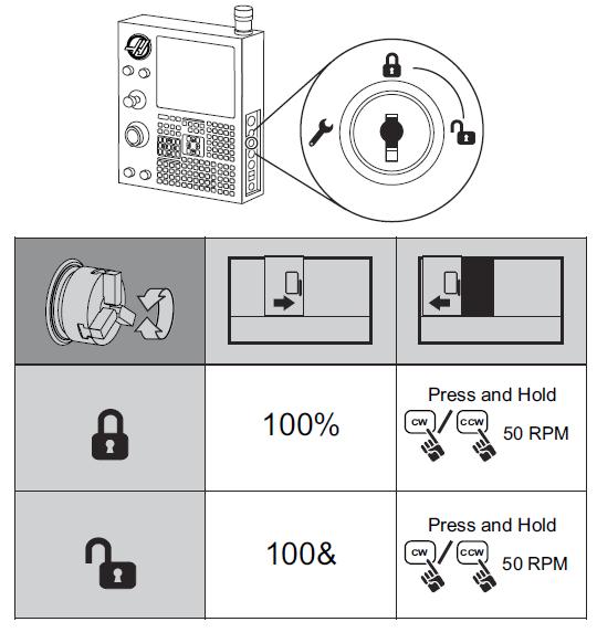
47 Lathe Axis and Absolute & Incremental Positioning. Control Pendant with Display Power On; Set Up, Edit and Operating Displays Jog Mode Function, Jog and Override Keys Manual Tool Offset Setting Part Zero Tool Pre-Setter with Probe Mode Keys Programming & G Codes Programs, Subroutines, Address Codes, M Codes, Defaults, Safety Line Display Keys Spindle Codes Graphics Mode Pendant Side Panel & Lock and Unlock Behavior Tailstock
48 Haas CNC Lathe Operator 2014 Haas CNC Lathe Programming 2015 Haas Lathe Operator s Manual 2016 Haas Programming Workbook 2015 Haas EBay Tutorials
Mill Series Training Manual. Haas CNC Mill Operator
 Haas Factory Outlet A Division of Productivity Inc Mill Series Training Manual Haas CNC Mill Operator Revised 022613 (032512) (printed 022613) This Manual is the Property of Productivity Inc The document
HFOMN/Haas CNC Series
 Haas Factory Outlet A Division of Productivity Inc HFOMN/Haas CNC Series Mill Operator Training Manual with NG2 Next Generation Control & VPS (Visual Programming System) Rev 2/2017 This Manual is the
 PROGRAMMING WORKBOOK HAAS AUTOMATION, INC 2800 Sturgis Rd Oxnard, CA 93030 January 2004 JANUARY 2004 PROGRAMMING HAAS AUTOMATION INC 2800 Sturgis Road Oxnard, California 93030 Phone: 805-278-1800 www
HAAS AUTOMATION, INC.
 PROGRAMMING WORKBOOK HAAS AUTOMATION, INC. 2800 Sturgis Rd. Oxnard, CA 93030 JUNE 1, 2000 JUNE 2000 PROGRAMMING CONTENTS INTRODUCTION... 1 THE COORDINATE SYSTEM... 2 MACHINE HOME... 5 ABSOLUTE AND INCREMENTAL
ADVANCED TECHNIQUES APPENDIX A
 A P CONTENTS þ Anilam þ Bridgeport þ Fanuc þ Yasnac þ Haas þ Fadal þ Okuma P E N D I X A ADVANCED TECHNIQUES APPENDIX A - 1 APPENDIX A - 2 ADVANCED TECHNIQUES ANILAM CODES The following is a list of Machinist
Conversational Programming for 6000i CNC
 Conversational Programming for 6000i CNC www.anilam.com P/N 634 755-22 - Contents Section 1 - Introduction Section 2 - Conversational Mode Programming Hot Keys Programming Hot Keys... 2-1 Editing Keys...
SHOP NOTES. GPocket Guide and Reference Charts. for CNC Machinists. Made in the U.S.A. WHAT S INSIDE THIS BOOKLET? Haas Automation, Inc.
 SHOP NOTES GPocket Guide and Reference Charts for CNC Machinists Made in the U.S.A. WHAT S INSIDE THIS BOOKLET? Decimal Equivalent Chart / Millimeter to Inch Chart Haas Mill G-Codes / Haas Mill M-Codes
GE FANUC 21 CONCEPT 55 TURN TEACHER GUIDE
 GE FANUC 21 CONCEPT 55 TURN TEACHER GUIDE 2/13/08 Version 2 Made by EMCO Authored by Chad Hawk Training Index Control Keyboard Pg 1 Fanuc 21 Control Machine Control Fanuc 21 Screen Pg 2 Fanuc 21 Keys Pg
Conversational Programming for 6000M, 5000M CNC
 Conversational Programming for 6000M, 5000M CNC www.anilam.com P/N 70000486F - Contents Section 1 - Introduction Section 2 - Conversational Mode Programming Hot Keys Programming Hot Keys... 2-1 Editing
Lesson 4 Introduction To Programming Words
 Lesson 4 Introduction To Programming Words All CNC words include a letter address and a numerical value. The letter address identifies the word type. The numerical value (number) specifies the value of
HAAS Mini Mill User s Manual
 Using the Haas Mini Mills HAAS Mini Mill User s Manual Stanford Product Realization Laboratory Version 1.3 166 1. Machine (Pre) Start-Up a. Check Oil Reservoir (at rear of machine). If Oil Level is below
2. INTRODUCTION TO CNC
 Q. Define NC Machines. 2. INTRODUCTION TO CNC A method of automation, in which various functions and processing of machine tools are controlled by letters and symbols. The general objective of NC technology
Lathe Operator s Manual
 Lathe Operator s Manual JUNE 2005 HAAS AUTOMATION INC. 2800 STURGIS ROAD OXNARD, CA 93030 TEL. 888-817-4227 FAX. 805-278-8561 www.haascnc.com 96-8700 revl Warranty Certificate Covering Haas Automation,
Programming Features PERFORMANCE & SPECIFICATIONS
 PERFORMANCE & SPECIFICATIONS Essentials Processor Intel Pentium Instruction Set 32-bit Performance Number of Cores 1 Processor Base Frequency 1.8 GHz Memory Data Storage 1 GB System Memory Installed 2
Mach4 CNC Controller Lathe Programming Guide Version 1.0
 Mach4 CNC Controller Lathe Programming Guide Version 1.0 1 Copyright 2014 Newfangled Solutions, Artsoft USA, All Rights Reserved The following are registered trademarks of Microsoft Corporation: Microsoft,
Software designed to work seamlessly with your CNC Masters machine. Made to work with Windows PC. Works with standard USB
 Software designed to work seamlessly with your CNC Masters machine Made to work with Windows PC Works with standard USB Clutter free interface. The software is engineered for the machine so you don t have
Lathe. Lathe Control Operating Manual 1000 Series Set Lathe X axis Part Zero
 Lathe Lathe Control Operating Manual 1000 Series Set Lathe X axis Part Zero Lathe Control Operating Manual 1000 Series 1. Introduction 1.1 Control Startup To open the control software double-click on the
COMPUTER NUMERICAL CONTROL OF MACHINE TOOLS
 COMPUTER NUMERICAL CONTROL OF MACHINE TOOLS Department of Mechanical Engineering and Aeronautics University of Patras, Greece Dr. Dimitris Mourtzis Associate professor Patras, 2017 1/52 Chapter 8: Two
Mach4 CNC Controller Mill Programming Guide Version 1.0
 Mach4 CNC Controller Mill Programming Guide Version 1.0 1 Copyright 2014 Newfangled Solutions, Artsoft USA, All Rights Reserved The following are registered trademarks of Microsoft Corporation: Microsoft,
OmniTurn Training Manual
 OmniTurn Training Manual Phone (631) 694-9400 Fax (631) 694-9415 1 2 OmniTurn Control Welcome to our world This manual will guide first time users to startup, home, enter, edit, and run programs. First
Conversational Programming for 6000i CNC
 Conversational Programming for 6000i CNC January 2008 Ve 01 634755-21 1/2008 VPS Printed in USA Subject to change without notice www.anilam.com P/N 634755-21 - Warranty Warranty ANILAM warrants its products
IEEM 215. Manufacturing Processes I Introduction to the ARIX CNC milling machine
 IEEM 215. Manufacturing Processes I Introduction to the ARIX CNC milling machine The image below is our ARIX Milling machine. The machine is controlled by the controller. The control panel has several
Maincon Control Software (Mill VER18 and Lathe VER11) - Load
 - Load") Maincon Control Software (Mill VER18 and Lathe VER11) - Load LAST UPDATED: 09/20/2018 Introduction This procedure tells you how to do these tasks on any CNC machine with a Maincon PCB: Install a new Maincon
Maincon Control Software (Mill VER18 and Lathe VER11) - Load LAST UPDATED: 09/20/2018 Introduction This procedure tells you how to do these tasks on any CNC machine with a Maincon PCB: Install a new Maincon
1000 Series Lathe Control OPERATING MANUAL. Specializing in CNC Automation and Motion Control
 1000 Series Lathe Control OPERATING MANUAL Specializing in CNC Automation and Motion Control 2 P age 6/24/15 G0131 This manual covers the operation of the 1000 Series Lathe Control. Formatting Overview:
Mach4 CNC Controller Mill Programming Guide Version 1.1 Build 3775
 Mach4 CNC Controller Mill Programming Guide Version 1.1 Build 3775 Copyright 2014 Newfangled Solutions, Artsoft USA, All Rights Reserved The following are registered trademarks of Microsoft Corporation:
Lathe - DXF Import and IPS Programming
 Haas Technical Documentation Lathe - DXF Import and IPS Programming Scan code to get the latest version of this document Translation Available INTRODUCTION AutoCAD DXF (Drawing Interchange Format, or Drawing
G & M Code REFERENCE MANUAL. Specializing in CNC Automation and Motion Control
 REFERENCE MANUAL Specializing in CNC Automation and Motion Control 2 P a g e 11/8/16 R0163 This manual covers definition and use of G & M codes. Formatting Overview: Menus, options, icons, fields, and
9000 CNC 9000 CNC: THE NEW STANDARD OF CONTROL. INTUITIVE EFFICIENT PRODUCTIVE
 3D Solid Model Graphics Solid Model with Tool Path Overlay 9000 CNC 9000 CNC: THE NEW STANDARD OF CONTROL. At Milltronics we are constantly refining our controls to simplify operation, shorten setup times
Polar coordinate interpolation function G12.1
 Polar coordinate interpolation function G12.1 On a Turning Center that is equipped with a rotary axis (C-axis), interpolation between the linear axis X and the rotary axis C is possible by use of the G12.1-function.
GE FANUC 21 CONCEPT 55 MILL ATC TEACHER GUIDE
 GE FANUC 21 CONCEPT 55 MILL ATC TEACHER GUIDE 11/1/07 Version 2 Made by EMCO Authored by Chad Hawk Training Index Control Keyboard Pg 1 Fanuc 21 Control Machine Control Fanuc 21 Screen. Pg 2 Fanuc 21 Keys.
3000M CNC Programming and Operations Manual for Two-Axis Systems
 3000M CNC Programming and Operations Manual for Two-Axis Systems www.anilam.com P/N 70000496G - Contents Section 1 - CNC Programming Concepts Programs... 1-1 Axis Descriptions... 1-1 X Axis... 1-2 Y Axis...
Conversational Programming for 6000M, 5000M CNC
 Conversational Programming for 6000M, 5000M CNC www.anilam.com P/N 70000486E - Warranty Warranty ANILAM warrants its products to be free from defects in material and workmanship for one (1) year from date
FAGOR AUTOMATION MC TRAINING MANUAL
 FAGOR AUTOMATION MC TRAINING MANUAL ACER MC TRAINING MANUAL 8 holes 1/2" depth grid pattern R0.125 1.5 6 unit: inch R0.25 4 1.25 2 2.675 1/2" depth rectangular pocket 1/2" depth circular pocket R0.75 8
Lesson 6 The Key Operation Procedures
 Lesson 6 The Key Operation Procedures Step-by-step procedures can keep you from having to memorize every function that you must perform on your CNC machining center. You will soon memorize procedures for
CNC PART PROGRAMMING
 CNC PART PROGRAMMING (1) Programming fundamentals Machining involves an important aspect of relative movement between cutting tool and workpiece. In machine tools this is accomplished by either moving
WINMAX LATHE NC PROGRAMMING
 WINMAX LATHE NC PROGRAMMING January 2018 v546nc The information in this document is subject to change without notice and does not represent a commitment on the part of Hurco Companies, Inc. (Hurco). The
Section 15: Touch Probes
 Touch Probes Touch Probe - Length Offset The tool setting probe is used with the UTILITY command to establish the length offset. It can also be used for tool breakage detection and setting tool diameter
MAX CONTROL FOR TURNING CENTERS
 MAX CONTROL FOR TURNING CENTERS Preliminary NC Programming Manual March 2005 PRE 704-0115-301, B Revision B The information in this document is subject to change without notice and does not represent a
CENTROID. T-SERIES Operator's Manual. Version 8.22 Rev U.S. Patent # Centroid Corp. Howard, PA 16841
 CENTROID T-SERIES Operator's Manual Version 8.22 Rev. 030826 U.S. Patent #6490500 2004 Centroid Corp. Howard, PA 16841 CHAPTER 1 - Introduction Window Description 1-1 Conventions 1-3 Machine Home 1-4 Keyboard
3300M/MK CNC Programming and Operations Manual
 3300M/MK CNC Programming and Operations Manual www.anilam.com P/N 70000381C - Contents Section 1 - CNC Programming Concepts Programs... 1-1 Axis Descriptions... 1-1 X Axis... 1-2 Y Axis... 1-2 Z Axis...
Century Star Turning CNC System. Programming Guide
 Century Star Turning CNC System Programming Guide V3.5 April, 2015 Wuhan Huazhong Numerical Control Co., Ltd 2015 Wuhan Huazhong Numerical Control Co., Ltd Preface Preface Organization of documentation
Ultimate Screen Reference Guide
 MACHMOTION Ultimate Screen Reference Guide 8/11/2011 Everything you need to know to use and setup the MachMotion Ultimate Screen. MachMotion Version 1.0.2 2 P a g e Copyright 2011, MachMotion.com All rights
Linear Interpolation and Dwell Cycle. Dr. Belal Gharaibeh
 Linear Interpolation and Dwell Cycle Dr. Belal Gharaibeh 1 Linear Interpolation Linear interpolation is used in part programming to make a straight cutting motion from the start position of the cut to
Mach4 Lathe G-Code and M-Code Reference
 Mach4 Lathe G-Code and M-Code Reference Chapter 1: Introduction G-Code is a special programming language that is interpreted by Computer Numerical Control (CNC) machines to create motion and other tasks.
CNC MILLING MACHINE NER VC180)
") CNC MILLING MACHINE (SPINNER NER VC180) PREPARED BY: RAFIZAH BINTI ABDUL RASHID NOR ZAIAZMIN BIN YAHAYA PREPARED FOR: ADVANCED MANUFACTURING TECHNOLOGY (EPT 311) Page 1 of 12 TURNING ON THE CNC MILLING
CNC MILLING MACHINE (SPINNER NER VC180) PREPARED BY: RAFIZAH BINTI ABDUL RASHID NOR ZAIAZMIN BIN YAHAYA PREPARED FOR: ADVANCED MANUFACTURING TECHNOLOGY (EPT 311) Page 1 of 12 TURNING ON THE CNC MILLING
COPYCAT NEW FANGLED SOLUTIONS 2/6/2009
 1.0 INTRODUCTION 1.1 CopyCat is a unique wizard used with MACH3. It is not a stand alone program. This wizard will allow you to jog a machine around and create a Gcode file from the movement. 2.0 REQUIREMENTS
HAAS AUTOMATION, INC.
 PROGRAMMING WORKBOOK HAAS AUTOMATION, INC. 2800 Sturgis Rd. Oxnard, CA 93030 June 2006 JUNE 2006 PROGRAMMING HAAS AUTOMATION INC. 2800 Sturgis Road Oxnard, California 93030 Phone: 805-278-1800 www.haascnc.com
JUNE 2005 HAAS AUTOMATION INC STURGIS ROAD OXNARD, CA TEL FAX
 Mill Operator s Manual JUNE 2005 HAAS AUTOMATION INC. 2800 STURGIS ROAD OXNARD, CA 93030 TEL. 888-817-4227 FAX. 805-278-8561 www.haascnc.com 96-8000 revl Warranty Certificate Covering Haas Automation,
Mach4 Industrial Mill Operations Guide
 Mach4 Industrial Mill Operations Guide 1 Copyright 2014 Newfangled Solutions, Artsoft USA, All Rights Reserved The following are registered trademarks of Microsoft Corporation: Microsoft, Windows. Any
CNC C6/C64/C64T PROGRAMMING MANUAL (LATHE TYPE) BNP-B2264D(ENG)
 BNP-B2264D(ENG)") CNC C6/C64/C64T PROGRAMMING MANUAL (LATHE TYPE) BNP-B2264D(ENG) MELDAS is a registered trademark of Mitsubishi Electric Corporation. Other company and product names that appear in this manual are trademarks
CNC C6/C64/C64T PROGRAMMING MANUAL (LATHE TYPE) BNP-B2264D(ENG) MELDAS is a registered trademark of Mitsubishi Electric Corporation. Other company and product names that appear in this manual are trademarks
Welcome to. the workshop on the CNC 8055 MC
 Welcome to the workshop on the CNC 8055 MC Sales Dpt-Training: 2009-sept-25 FAGOR CNC 8055MC seminar 1 Sales Dpt-Training: 2009-sept-25 FAGOR CNC 8055MC seminar 2 This manual is part of the course for
VMC600II VMC800II VMC1000II
 OPERATOR S MANUAL Revised: March 15, 2001 VMC600II VMC800II VMC1000II Vertical Machining Centers Equipped with the Hardinge / Fanuc Control System II Manual No. M-378 Litho in U.S.A. Part No. M -0009500-0378
CHAPTER 12. CNC Program Codes. Miscellaneous CNC Program Symbols. D - Tool Diameter Offset Number. E - Select Work Coordinate System.
 General CHAPTER 12 CNC Program Codes The next three chapters contain a description of the CNC program codes and parameters supported by the M-Series Control. The M-Series Control has some G codes and parameters
2000 Series Mill / Router Operating Manual
 2000 Series Mill / Router Operating Manual 1. Introduction 1.1 Control Startup To open the control software double-click on the profile icon on the desktop. Control Icon 1.2 Overview This manual gives
dfab Laguna CNC Manual With FANUC Control
 dfab Laguna CNC Manual With FANUC Control 1 Introduction Throughout this manual we use different nomenclature for [HARD KEYS] and (SOFT KEYS). A [HARD KEY] is a button on the CONTROL PANEL (upper panel)
CENTROID. M-SERIES Operator's Manual. Version 8.22 Rev U.S. Patent # Centroid Corp. Howard, PA 16841
 CENTROID M-SERIES Operator's Manual Version 8.22 Rev. 030826 U.S. Patent #6490500 2004 Centroid Corp. Howard, PA 16841 CNC Control Information Sheet Fill out the following and fax back to Centroid Tech
3000M CNC Programming and Operations Manual for Three- and Four-Axis Systems
 3000M CNC Programming and Operations Manual for Three- and Four-Axis Systems www.anilam.com 70000504H - Warranty Warranty ANILAM warrants its products to be free from defects in material and workmanship
T-SERIES Operator s Manual
 T-SERIES Operator s Manual CNC12 Version 4.12 U.S. Patent #6490500 c 2018 Centroid Corp. Howard, PA 16841 Throughout this manual and on associated products where applicable, in accordance with ANSI Z535,
List of Macro Variables
 APPENDIX C List of Macro Variables Variable Purpose Page #0 Null variable 22 #1 #33 Local variables 28 #34 #99 Not available 28 #100 #199 Common variables 28 #200 #499 Not available 28 #500 #999 Permanent
6000i CNC User s Manual
 6000i CNC User s Manual January 2008 Ve 02 627785-21 1/2008 VPS Printed in USA Subject to change without notice www.anilam.com P/N 627785-21 - Warranty Warranty ANILAM warrants its products to be free
OKUMA MACHINING CENTER OPERATORS GUIDE OSP P200M THiNC
 OKUMA MACHINING CENTER OPERATORS GUIDE OSP P200M THiNC OSP P200 Mill Training Rev1 1 OKUMA MACHINING CENTER OPERATORS GUIDE Scope 4 Section 1 Guide to Controls on Operation Panels 5 Section 2 Manual Tool
5000M CNC Programming and Operations Manual
 5000M CNC Programming and Operations Manual www.anilam.com P/N 70000508G - Warranty Warranty ANILAM warrants its products to be free from defects in material and workmanship for one (1) year from date
ACR-MotionMax Programmer's Reference Manual
 ACR-MotionMax Programmer's Reference Manual Programmer's Reference Manual Programming Information - 1 User Information ACR Series products are used to control electrical and mechanical components of motion
Mill - DXF and IPS Programming
 Haas Technical Documentation Mill - DXF and IPS Programming Scan code to get the latest version of this document Translation Available INTRODUCTION AutoCAD DXF (Drawing Interchange Format, or Drawing Exchange
FAGOR 800T CNC OPERATING MANUAL. Ref (in)
") FAGOR 800T CNC OPERATING MANUAL Ref. 9701 (in) ABOUT THE INFORMATION IN THIS MANUAL This manual is addressed to the machine operator. It includes the necessary information for new users as well as advanced
FAGOR 800T CNC OPERATING MANUAL Ref. 9701 (in) ABOUT THE INFORMATION IN THIS MANUAL This manual is addressed to the machine operator. It includes the necessary information for new users as well as advanced
Operation Manual (B) KVR-2418 (24L) Fanuc OiMD CNC. KENT INDUSTRIAL (USA) INC Edinger Ave., Tustin, CA 92780
 KVR-2418 (24L) Fanuc OiMD CNC. KENT INDUSTRIAL (USA) INC Edinger Ave., Tustin, CA 92780") Operation Manual (B) KVR-2418 (24L) Fanuc OiMD CNC KENT INDUSTRIAL (USA) INC. 1231 Edinger Ave., Tustin, CA 92780 Tel: (714) 258-8526 Fax: (714) 258-8530 Internet: WWW.KENTUSA.COM KENT USA THE WAY TO AFFORDABLE
Operation Manual (B) KVR-2418 (24L) Fanuc OiMD CNC KENT INDUSTRIAL (USA) INC. 1231 Edinger Ave., Tustin, CA 92780 Tel: (714) 258-8526 Fax: (714) 258-8530 Internet: WWW.KENTUSA.COM KENT USA THE WAY TO AFFORDABLE
CNC Programming Simplified. EZ-Turn / TurnMill Tutorial.
 CNC Programming Simplified EZ-Turn / TurnMill Tutorial www.ezcam.com Copyright Notice This manual describes software that contains published and unpublished works of authorship proprietary to EZCAM Solutions,
VERTICAL MACHINING CENTER OPERATION MANUAL I-SERIES-CAM
 VERTICAL MACHINING CENTER OPERATION MANUAL I-SERIES-CAM 07.10,2010 FANUC 18M,0I,18I,21I 1. PREFACE... 1-1 2. INSTALLATION AND POWER ON... 2-1 2.1 INPUT POWER ON... 2-2 2.2 SPECIFICATIONS OF ELECTRICAL
CENTROID. T-SERIES Operator's Manual. CNC11 Version 3.14 Rev U.S. Patent # Centroid Corp. Howard, PA 16841
 CENTROID T-SERIES Operator's Manual CNC11 Version 3.14 Rev. 150409 U.S. Patent #6490500 2015 Centroid Corp. Howard, PA 16841 READ THIS MANUAL BEFORE USING THIS PRODUCT. FAILURE TO FOLLOW THE INSTRUCTIONS
G47 Text Engraving (Group 00) - Mill. Troubleshooting. How it Works. Haas Technical Documentation. Setting 85 is Too High for Shallow Text Engraving
 - Mill. Troubleshooting. How it Works. Haas Technical Documentation. Setting 85 is Too High for Shallow Text Engraving") Haas Technical Documentation G47 Text Engraving (Group 00) - Mill Scan code to get the latest version of this document Translation Available Troubleshooting Setting 85 is Too High for Shallow Text Engraving
Haas Technical Documentation G47 Text Engraving (Group 00) - Mill Scan code to get the latest version of this document Translation Available Troubleshooting Setting 85 is Too High for Shallow Text Engraving
NCT. PLC Programmer s Manual. Machine Tool Controls. From SW Version x.061 (M) (L)
 (L)") NCT Machine Tool Controls PLC Programmer s Manual From SW Version x.061 (M) (L) Produced and developed by NCT Automation kft. H1148 Budapest Fogarasi út 7 : Letters: 1631 Bp. P.O. Box 26 F Phone: (+36
NCT Machine Tool Controls PLC Programmer s Manual From SW Version x.061 (M) (L) Produced and developed by NCT Automation kft. H1148 Budapest Fogarasi út 7 : Letters: 1631 Bp. P.O. Box 26 F Phone: (+36
Table of Contents. Fadal. Operator Manual
 Table of Contents Power On/Off... 3 Pre-Startup Checks... 3 Power On for System 97/99... 4 Automatic Cold Start... 5 Wrong Power Off Procedure... 6 Auto Startup Program... 7 Power Off Procedure... 9 Pendant...
2. (05. 10) CNC TURNING CENTER
 CNC TURNING CENTER") 2. (05. 10) CNC TURNING CENTER World Top Class Quality HYUNDAI-KIA Machine High Speed, High Accuracy, High Rigidity CNC Turning Center High Productivity, Versatile & Integrated Lathe High Speed, High Accuracy
2. (05. 10) CNC TURNING CENTER World Top Class Quality HYUNDAI-KIA Machine High Speed, High Accuracy, High Rigidity CNC Turning Center High Productivity, Versatile & Integrated Lathe High Speed, High Accuracy
Xbox gamepad CNC pendant user manual
 Patrik Tegelberg 2017-09-04 Xbox gamepad CNC pendant user manual Computer controlled manufacturing machines are awesome, and not designed for manual cutting. This controller, for LinuxCNC, maintains the
TOOLPATHS TRAINING GUIDE. Sample. Distribution. not for MILL-LESSON-4-TOOLPATHS DRILL AND CONTOUR
 TOOLPATHS TRAINING GUIDE MILL-LESSON-4-TOOLPATHS DRILL AND CONTOUR Mill-Lesson-4 Objectives You will generate a toolpath to machine the part on a CNC vertical milling machine. This lesson covers the following
Wizard 550 READOUTS REFERENCE MANUAL
 Wizard 550 READOUTS REFERENCE MANUAL Wizard 550 Key Layout Axis Keys Numeric Keypad Display Area Enter key Soft keys Power Indicator light Wizard 550 Soft Keys There are three pages of soft key functions
CNC Turning. Module2: Introduction to MTS-TopTurn and G & M codes. Academic Services PREPARED BY. January 2013
 CNC Turning Module2: Introduction to MTS-TopTurn and G & M codes PREPARED BY Academic Services January 2013 Applied Technology High Schools, 2013 Module2: Introduction to MTS-TopTurn and G & M codes Module
6 Series Mill Controller Operation Manual
 6 Series Mill Controller Operation Manual Date: 2013/10/25 Version: 1.1 Contents 1 Function Key and System Configuration... 4 1.1 Main Screen Sections... 4 1.2 CNC System Configuration... 5 1.3 Coordinate...
Introduction CAUTION. Details described in this manual
 Introduction This manual is a guide for using the MELDAS 60/60S Series, MELDASMAGIC64. Programming is described in this manual, so read this manual thoroughly before starting programming. Thoroughly study
CNC Programming Simplified. EZ-Turn Tutorial.
 CNC Programming Simplified EZ-Turn Tutorial www.ezcam.com Copyright Notice This manual describes software that contains published and unpublished works of authorship proprietary to EZCAM Solutions, Inc.
Warranty. Student Workbook for Three-Axis Systems
 www.anilam.com P/N 70000505 - Warranty Warranty ANILAM warrants its products to be free from defects in material and workmanship for one (1) year from date of installation. At our option, we will repair
VisualCAM 2018 for SOLIDWORKS-TURN Quick Start MecSoft Corporation
 2 Table of Contents Useful Tips 4 What's New 5 Videos & Guides 6 About this Guide 8 About... the TURN Module 8 Using this... Guide 8 Getting Ready 10 Running... VisualCAM for SOLIDWORKS 10 Machining...
GE Fanuc Automation. Series 16i / 18i / 21i Model TA Manual Guide. Computer Numerical Control Products. Operator's Manual
 GE Fanuc Automation Computer Numerical Control Products Series 16i / 18i / 21i Model TA Manual Guide Operator's Manual B-63344EN/01 July 1998 Warnings, Cautions, and Notes as Used in this Publication GFL-001
CONTENTS I GENERAL GENERAL CONTROLLED AXES PREPARATORY FUNCTION (G FUNCTION) INTERPOLATION FUNCTIONS 4-1
 INTERPOLATION FUNCTIONS 4-1") CONTENTS I GENERAL 1-0 1. GENERAL 1-1 1.1 GENERAL FLOW OF OPERATION OF CNC MACHINE TOOL 1-1 1.2 NOTES ON READING THIS MANUAL 1-2 II PROGRAMMING 1-0 1. GENERAL 1-1 1.1 TOOL MOVEMENT ALONG WORKPIECE PARTS
CONTENTS I GENERAL 1-0 1. GENERAL 1-1 1.1 GENERAL FLOW OF OPERATION OF CNC MACHINE TOOL 1-1 1.2 NOTES ON READING THIS MANUAL 1-2 II PROGRAMMING 1-0 1. GENERAL 1-1 1.1 TOOL MOVEMENT ALONG WORKPIECE PARTS
Manufacturing Processes with the Aid of CAD/CAM Systems AMEM 405
 AMEM 405 slide 1 Manufacturing Processes with the Aid of CAD/CAM Systems AMEM 405 Dr. Sotiris Omirou AMEM 405 slide 2 CONTENTS 1. CAD/CAM definition 2. Review of Milling Process 3. Know The CNC Machine
6 Series Mill Controller Operation Manual
 6 Series Mill Controller Operation Manual Date: 2015/11/13 Version: 1.3 2 Contents 1 Function Key and System Configuration... 4 1.1 Main Screen Sections... 4 1.2 CNC System Configuration... 5 1.3 Coordinate...
HAAS SERVICE AND OPERATOR MANUAL ARCHIVE. VS Series Operators Manual G RevG English June 2003
 Haas Technical Publications Manual_Archive_Cover_Page Rev A June 6, 2013 HAAS SERVICE AND OPERATOR MANUAL ARCHIVE VS Series Operators Manual 96-0103G RevG English June 2003 This content is for illustrative
User s Manual V MillPlus IT. NC Software
 User s Manual V600-02 MillPlus IT NC Software 538 952-02 538 953-02 538 954-02 538 955-02 538 956-02 English (en) 6/2008 Controls on the visual display unit Select window User keys Manual operation Axis-direction
300S READOUTS REFERENCE MANUAL
 300S READOUTS REFERENCE MANUAL 300S Key Layout 1 Display Area 2 Soft keys 3 Power Indicator light 4 Arrow Keys: Use the UP/DOWN keys to adjust the screen contrast. 5 Axis Keys 6 Numeric Keypad 7 ENTER
Turning ISO Dialect T
 SINUMERIK 802D Short Guide 09.2001 Edition Turning ISO Dialect T User Documentation SINUMERIK 802D Turning ISO Dialect T Short Guide 09.2001 Edition Valid for Control Software Version SINUMERIK 802D 1
Turning your ideas into reality Novakon MPG Manual
 Novakon MPG Manual The E-STOP switch button on your Novakon CNC Control Pendant only provides Emergency STOP signal to Mach3 CNC application. For further protection in CNC operation, other emergency protection
Section 20: Graphics
 Section 20: Graphics CNC 88HS Graphics Graphics Menu The graphics menu of the page editor has been designed to allow the user to view the part path of the current program in memory. The graphics can be
NC CODE REFERENCE MANUAL
 NC CODE REFERENCE MANUAL Thank you very much for purchasing this product. To ensure correct and safe usage with a full understanding of this product's performance, please be sure to read through this manual
Computer Aided Engineering Applications 3. Advanced Manufacturing 3.5 NC programming 3.6 Automated Manufacturing systems 3.7 Rapid prototyping
 Computer Aided Engineering Applications 3. Advanced Manufacturing 3.5 NC programming 3.6 Automated Manufacturing systems 3.7 Rapid prototyping Engi 6928 - Fall 2014 3.5 Part programming Structure of an
Turning Hardinge GS 51MS Turning Center
 Turning Hardinge GS 51MS Turning Center Quotation to: ABMNameAlpha Quotation Number: SOHDocumentOrderInvoice Contact: Contact Name Address: ShipToAddressLine1 ShipToAddressLine2 ShipToAddressLine3 ShipToAddressLine4
Coordinate System Techniques
 Coordinate System Techniques In this lesson, we ll show some advanced implications of what can be done with coordinate systems. For the most part, this lesson applies to machining centers. But there are
OPERATION MANUAL. TYPE:C-Type Series CONTROLLER:FANUC 0iMD / 18iMB / 31iB VERSION NO.:AFEQFI03 DATE:2012/05/03 AWEA MECHANTROINC CO.
 OPERATION MANUAL TYPE:C-Type Series CONTROLLER:FANUC 0iMD / 18iMB / 31iB VERSION NO.:AFEQFI03 DATE:2012/05/03 AWEA MECHANTROINC CO., LTD NO.15,Keyuan 2nd Rd., Taichung City, Taiwan. 40763 TEL:886-4-2462-9698
PC-BASED NUMERIC CONTROLLER
 Ncstudio PC-BASED NUMERIC CONTROLLER PROGRAMMING MANUAL there is WEIHONG Where there is motion control Thank you for choosing our products! This manual will help you acquaint with our products and learn
MELDAS, MELDASMAGIC, and MELSEC are registered trademarks of Mitsubishi Electric Corporation. The other company names and product names are
 MELDAS, MELDASMAGIC, and MELSEC are registered trademarks of Mitsubishi Electric Corporation. The other company names and product names are trademarks or registered trademarks of the respective companies.
Digital display for EMCO milling machines
 Digital display for EMCO milling machines Input box 7 8 9 1 X Y Z HELP 4 5 6 1 2 3 0. - ESC 3 CE ENT R + R - 2 REF RST 1... Screen (working window, displays) 2... 5 soft keys (function depends on the respective