USER GUIDE Digital programmable Thermostat GUIDE D UTILISATION Thermostat digital programmable 42-87
|
|
|
- Giles Curtis
- 6 years ago
- Views:
Transcription
1 BT DP-01
2 2
3 USER GUIDE GB Digital programmable Thermostat 4-41 GUIDE D UTILISATION F Thermostat digital programmable Bedienungsanleitung D Programmierbarer digitaler Funkthermostat GUÍA DE USUARIO ES Termostato digital programable GUIA DO UTILIZADOR PT Termostato programável digital HANDLEIDING NL Digitale programmeerbare Thermostaat
4 IMPORTANT! Before starting work the installer should carefully read this Installation & Operation Manual, and make sure all instructions contained therein are understood and observed. - The thermostat should be mounted, operated and maintained by specially trained personnel only. Personnel in the course of training are only allowed to handle the product under the supervision of an experienced fitter. Subject to observation of the above terms, the manufacture shall assume the liability for the equipment as provided by legal stipulations. - All instructions in this Installation & Operation manual should be observed when working with the controller. Any other application shall not comply with the regulations. The manufacturer shall not be liable in case of incompetent use of the control. Any modifications and amendments are not allowed for safety reasons. The maintenance may be performed by service shops approved by the manufacturer only. - The functionality of the controller depends on the model and equipment. This installation leaflet is part of the product and has to be obtained. 4
5 APPLICATION - The thermostats of the BT series are developed to control and manage all type of heating installations. - The controllers have been designed for use in residential rooms, office spaces and industrial facilities. Verify that the installation complies with existing regulations before operation to ensure proper use of the installation. SAFETY INSTRUCTIONS Before starting work disconnect power supply! - All installation and wiring work related to the thermostat must be carried out only when de-energized. The appliance should be connected and commissioned by qualified personnel only. Make sure to adhere to valid safety regulations. - The thermostats are neither splash- nor drip-proof. Therefore, they must be mounted at a dry place. - Do not interchange the connections of the sensors and the connections under any circumstances! Interchanging these relays connections may result in life endangering electrical hazards or the destruction of the appliance and the connected sensors and other appliances. 5
6 Table of content 1 Presentation. Fehler! Textmarke nicht definiert. 1.1 Keyboard... Fehler! Textmarke nicht definiert. 1.2 Display & LEDFehler! Textmarke nicht definiert. 2 First InstallationFehler! Textmarke nicht definiert. 2.1 Batteries installationfehler! Textmarke nicht definiert. 2.2 Time and Date adjustmentfehler! Textmarke nicht definiert. 2.3 Starting... Fehler! Textmarke nicht definiert. 3 Working mode definitionfehler! Textmarke nicht definiert. 3.1 Manual mode Comfort Fehler! Textmarke nicht definiert. 3.2 Manual mode, Reduced Fehler! Textmarke nicht definiert. 3.3 OFF mode. Fehler! Textmarke nicht definiert. 3.4 Automatic modefehler! Textmarke nicht definiert. 3.5 Program mode Fehler! Textmarke nicht definiert. 6
7 3.6 Holiday modefehler! Textmarke nicht definiert. 3.7 Timer mode Fehler! Textmarke nicht definiert. 4 Special functionfehler! Textmarke nicht definiert. 4.1 Keyboards lock Function Fehler! Textmarke nicht definiert. 4.2 Information. Fehler! Textmarke nicht definiert. 5 Parameter s menufehler! Textmarke nicht definiert. 6 Technical characteristicsfehler! Textmarke nicht definiert. 7 Troubleshooting & SolutionFehler! Textmarke nicht definiert. 7

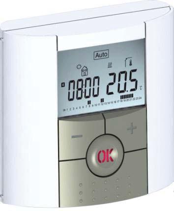
8 1 Presentation Electronic programmable thermostat with LCD display specially designed to control different type of heating systems. 8
9 It will be your best partner to optimize your energy consumption and increase your comfort. - Modern design with soft touch material. - Wiring & Installation simplified. - Easy program creation function. - Weekly programmable by step of 30min. - Temporary override function. - Anti freeze function. - Holiday or Reception function. - EEPROM non volatile memory. - 2 AAA batteries for 2 years operating life. - 2 Wires output for a maximum possibility of use. - 2 parameter menus, (User and Installer) In option - External sensor with several possibilities of regulation. (Floor, combined ) 9
10 1.1 Keyboard Minus Key (-) Plus Key (+) Validation Key (OK) Status LED Left Navigation key ( ) Right navigation key ( ) Escape key ( ) Edition key ( ) 10

11 1.2 Display & LED Red Fix (when backlight is lit up): Heating demand Green flash: your validation is required Red flash: Error on sensor or batteries
12 1. Current day of the week 2. Operating mode menu (active mode is framed). 3. Program number or parameter number if 4 is displayed. 4. Installation Parameter menu. 5. Type of sensor used and temperature displayed. Regulation => Internal or external ambient sensor. Regulation => Floor sensor. Regulation => Internal sensor with Floor limitation. View of the outside temperature 6. Heating demand indication. 7. Low batteries indicator. 8. C or F unit indicator 9. Setting or measured temperature if 5 is displayed. Parameter value if 4 is displayed. 12
13 10. Temporary override function activated, or ITCS function if blinking. 11. Time or parameter title if 4 is displayed. 12. Program of the current day (the current time bar blinks) 13. Pictogram for program creation, program state in normal operating mode. 14. Key lock indicator 13
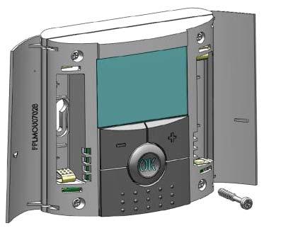
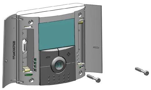
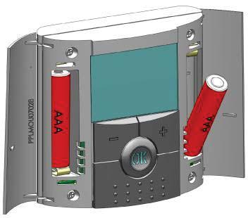
14 2 First Installation This section will guide you to set up your thermostat for the first time. 2.1 Batteries installation - Open the two side s covers and Insert the 2 AAA Alkaline supplied batteries (or remove the small protection sticker if the batteries are already installed in the compartment) - Close the two side s covers. - Now your thermostat will propose you to adjust the current time and date. 2.2 Time and Date adjustment Each time a value blinks, you can adjust it with the (-) and (+) keys, once the value is chosen, validate it with the (OK) key. The thermostat will jump automatically to the next value. Note: you can always come back to the previous value by pressing the escape key ( ). 14
15 List order of the time and date adjustments: Time and day: Adjustment of the hours, Adjustment of the minutes Adjustment of the day (1 = Monday) Date: Adjustment of the day number Adjustment of the month number (01 to 12) Adjustment of the year (Century) Adjustment of the year Then the message Save and blinking green LED appears, press (OK) to validate the adjusted time and date. You can always reach the time and date adjustments, by pressing and maintaining the edition ( ) key during 2 seconds in normal operating modes. 15
16 2.3 Starting The thermostat is now ready to works. The default working mode will be automatic with a standard built-in program P1. Monday to Friday 20 C 18 C 07:00 09:00 17:00 23:00 Saturday & Sunday 20 C 18 C 08:00 23:00 16
 key to lit-up the backlight, and then press another time the")
17 Note: You can customise your program as you want, See the next part Working mode definition chapter Program for more explanation. Curent stage of the program Program followed Curent time At any time, when the backlight is extinct, press the (OK) key to lit-up the backlight, and then press another time the (OK) key to show the current setting temperature 17

18 3 Working mode definition How to change the working mode? - Open the small center cover to have access to the navigation keys ( ) or ( ). - You can now press theses keys to display the working mode line. Move the frame cursor on the desired working mode and press (OK) to enter in the operating mode you have chosen. 18
19 3.1 Manual mode Comfort Manual working mode, the comfort setting temperature will be followed all the time. By pressing (-) or (+) keys, the comfort setting temperature starts to blink and can be adjusted. 3.2 Manual mode, Reduced Manual working mode, the reduced setting temperature will be followed all the time. By pressing (-) or (+) keys, the reduced setting temperature starts to blink and can be adjusted. 3.3 OFF mode Use this mode if you need to switch off your installation. Be Careful: In this mode your installation can freeze. 19
20 - At any time, when display is off, press on the (Ok) key to display a few seconds the current temperature and time. - To restart your installation, use the navigation keys ( ) or ( ). 3.4 Automatic mode In this mode the thermostat will follow the chosen program (Built-in or customized) according to the actual time and the Comfort and Reduced setting temperatures. You can easily override, until next program step, the current program temperature by changing the value with (-) or (+). Setting temperature will blink. The small hand logo will be displayed when override function is active. If hand logo blinks then ITCS is ongoing. 20
21 3.5 Program mode Current day Program followed Program of the day When you enter in the Program mode, the first operation is to chose the program number with (-) or (+) keys. You can choose between a built-in program P1 to P9 or a user program U1 to U4. 21
22 If you chose a Built-in program P1 to P9, You can only see and chose the program. P1: Morning, Evening & Weekend P2: Morning, Midday, Evening & Weekend P3: Day & Weekend P4: Evening & Weekend P5: Morning, Evening (Bathroom) P6: Morning, afternoon & Weekend P7: 7H 19H (Office) P8: 8H 19H & Saturday (Shop) P9: Weekend (Secondary house) (See the Annexe parts to view a complete description of the Built-in program) - Use the navigation keys ( ) or ( ) to change the program day displayed. - Press the (OK) key to confirm your choice and come back to the main screen (in AUTO mode) 22
23 If you chose a user program U1 to U4, As above you can choose the program, see it, but you can also customise it. Default setting: U1, U2, U3, U4 = Comfort all week - Press on the edition key ( ) to customise a user program. Symbols and explanation for program creation: First step of the day ( Comfort temp.) The wakeup hour need to be adjusted. Middle step of the day ( Reduced temp.) The leaving hour need to be adjusted 23
24 Middle step of the day ( Comfort temp.) The comeback hour will need to be adjusted Last step of the day ( Reduced temp.) The sleeping hour need to be adjusted - The program step is 30 minutes - Each time a value or icon blinks you are invited to make a choice with (-) or (+) keys, once the choice is made press the (OK) key to jump to the following step. - The program creation will always start with the day 1 (Monday). Once you have pressed the ( display will appear: ) key, the following 24
25 Now you are invited to adjust the hour of the first step of the program with (-) or (+), Press (OK) to validate and go to the following step. 25
26 Now you are invited to choose the type of the next step of the program (blinking icons), 2 choices will be possible: - 1 st choice is to choose the sleep icon. (End of the day) - 2 nd choice is to choose the leaving icon, to add one step to the program during the day. When the choice is made, press (OK) to validate. Then you can adjust the step hour with (-) or (+), 26
 or (+) the hour of the comeback step.")
27 When step hour is set press (OK) to jump to the next step. You will be directly invited to adjust with (-) or (+) the hour of the comeback step. Press (OK) to validate and go to the following step. 27
 - 2 nd choice is to choose the leaving icons, to add another step to the program during the day.")
28 You are again invited to choose the type of the next step of the program (blinking icons), 2 choices will be possible: - 1 st choice is to choose the sleep icons. (End of the day) - 2 nd choice is to choose the leaving icons, to add another step to the program during the day. When the choice is made, press (OK) to valid and you can adjust the hour of this step with (-) or (+), 28


29 Press (OK) to validate and finish the edition of the first day. Now you can choose to copy the program day just created to subsequent days. Change the choice Yes or no with (-) or (+) and validate your choice with (OK). - If you select no, you will be invited to create a program for Tuesday (repeat the previous method to built it.) - If you select Yes, you will have the possibility to copy the program to the following day (on Tuesday 29
 key to save your program and return to AUTO operating mode following your user program.")
30 on Wednesday... up to the last day of the week (7 Sunday). When you press (OK) on the last day (7 Sunday) you will be invited to SAVE your program. Then the message Save and blinking green LED appears: Press (OK) key to save your program and return to AUTO operating mode following your user program. Press the escape key ( ) to erase your user program changes and come back to operating mode. 30
31 3.6 Holiday mode The Holiday mode allows you to set the anti-freeze temperature for a selected number of days - You can adjust, the duration in day d with (-) or (+), press (OK) to start. (Adjustable 1 to 99 days) - The anti-freeze setting temperature is fixed and can be adjusted in the parameter menu number 06 HG, see chapter 6. (Default value 10 C) The logo will blink and the number of days left is displayed until the end of the period. If you want to stop the Holiday function before the end, set the duration period to no with (-) key. 31
32 3.7 Timer mode The Timer mode allows you to adjust, the temperature and the duration for a special time. This function can be used when you stay at home for several days, or if you want to override the program for some time (reception...) - You can first adjust, the duration in hours H if below 24H, then in day d with (-) or (+), press (OK) to validate. (Adjustable 1 Hour to 99 days) - In a second time, you can adjust the desired setting temperature with (-) or (+), press (OK) to start the function. (Default value 22 C) The logo will be blinks and the number of hours /days left is displayed until the end of the period. If you want to stop the Timer function before the end, set the duration period to no with (-) key. 32
33 4 Special function 4.1 Keyboards lock Function Use this function to prevent all change of your settings (In a child room, public area ) - To activate the Key lock function, first press maintain the escape key ( ) and then press simultaneously on the edition key ( ). - The logo will be displayed on the screen. - Repeat the same procedure to unlock the key board. 4.2 Information With this function You can quickly view all currents temperatures of the probe sensors connected to your thermostat (Floor, external or outside sensor) by several presses on the escape key ( ).This Scroll function is only available in the main screen. You can view: 33
34 - The current setting temperature followed by the thermostat. - The ambient temperature - If external sensor is connected: The Floor temperature if it is used as floor sensor. The outside temperature if it used as outside sensor. If Parameter SenS is set on Air, the external sensor will be used as an outside temperature sensor 34
 or ( ), once the parameter chosen,")
35 5 Parameter s menu Your thermostat has a parameter s menu, in order to enter in this menu, press and maintain the edition key ( ) during 5sec. Then parameter menu will appear and first parameter screen will be displayed: Now you can select a parameter which must be adjusted with the navigation keys ( ) or ( ), once the parameter chosen, toggle the value with the (OK) key, modify it with (-) or (+) and confirm your adjustment with (OK). To leave the parameter menu, choose the parameter «End» and press (OK). 35
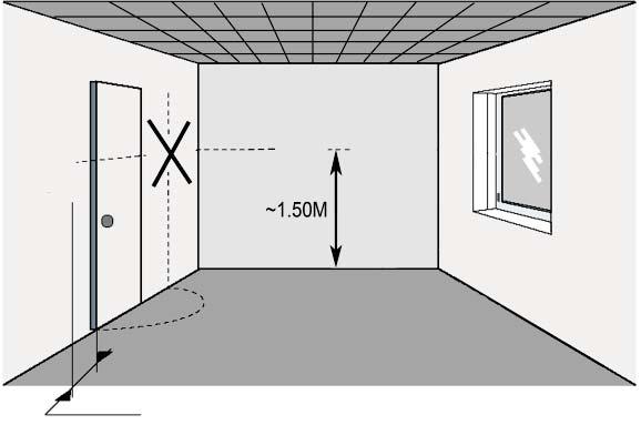
36 N Default value & other possibilities 01 deg: Unit of the temperatures displayed C Celsius F Fahrenheit 02 : Selection of the Time clock unit 24H (24:00) 12H (12:00 AM /PM) 03 dst: Daylight Summer time change Summer<->Winter YES automatic change according to date. no no daylight summer time automatic change. 04 AirC: Calibration of the internal probe The calibration must be done after 1 day working with the same setting temperature in accordance with the following description: Put a thermometer in the room at 1.5M distance from the floor (like the thermostat) and check the real temperature in the room after 1 hour. When you enter on the calibration parameter no is displayed on the right to indicate no calibration has made. To enter the value shown on the thermometer, use the (-) or (+) keys to enter the real value. Then, press (Ok) 36
37 to confirm. The message Yes should be displayed; the value will be stored in the internal memory. If you need to erase a calibration press on the escape key ( ). The old value will be erased and the message no will be displayed. * Pay attention: Only the heating element driven by the thermostat must be used during the complete step of the calibration. 05 OutC, AMbC, FlrC: Calibration of the external wired probe Same calibration method as described in parameter 04 AirC above. 06 HG: Anti-freeze temperature used in Holiday mode Default value 10 C. Use the (-) or (+) keys to change the anti-freeze setting temperature. Then press (Ok) to confirm. 07 ITCS: YES, no The Intelligent Temperature Control System will activate your installation in advance (2 hours maximum) to assure the desired temperature at the 37
38 hour programmed following your weekly program. This automatic control system works in the following way: When you start your thermostat for the first time, it will measure the time taken by your installation to reach the set temperature. The thermostat will re-measure this time at each program change to compensate external temperature change & influence. You can now program your thermostat without the need to adjust the temperature in advance because your thermostat does it automatically for you. 08 Clr ALL: Reset to Factory setting Press and maintain (Ok) key during 10s to reset Set points temperatures and user parameters in this menu to factory default settings. User programs will also be resetted. * Pay attention: Ensure you that you have all necessary elements to resetup your installation before to use this function. 09 Software version VErS 10 End: Exit the parameter s menu Press (OK) key to exit installation parameter menu and 38
39 return to normal operation. 6 Technical characteristics Measured temperature precision Environmental: Operating temperature: Shipping and storage temperature: Setting temperature range Comfort, Reduced Holiday (Antifreeze) Timer Regulation characteristics Electrical Protection Power Supply Operating life Receiver Output Maximum load 0.1 C 0 C - 40 C -10 C to +50 C 5 C to 35 C by 0,5 C step 10 C (adjustable) 5 C to 35 C Proportional Band (PWM 2 C for 10min cycle) or Hysteresis of 0.5 C Class II - IP30 2 AAA LR03 1.5V Alkaline ~2 years Relay 5Amps 250Vac 3A in 230Vac (Free contact) 39
40 Optional External sensor 10k ohms at 25 C Software version Norms and homologation: Your thermostat has been designed in conformity with the following standards or other normative documents: Displayed in the user menu. EN : 2003 EN : 2002 EN : 2004 EN : 2001 Low voltage 2006/95/CE EMC 2004/108/CE 40
41 7 Troubleshooting & Solution Batteries Problem My BT DP-01 doesn t start - Check if the protection sticker on the batteries is removed. - Check the batteries orientation. - Check the capacity of the batteries My BT DP-01 Led, blinks in Red Problem on sensors Batteries level is too less The logo blinks (ambient sensor) - Contact your installer or seller. The logo blinks (Floor sensor) - Check the connection of the sensor. - Disconnect the sensor, and check it with an ohmmeter (the value must be around 10kohms) The logo blinks (Batteries) - Replace the batteries. 41
42 My BT DP-01 seems work correctly but the heating doesn t work correctly - Check the connections. - Check the power supply of the Output heating element. - Contact your installer. My BT DP-01 seems work correctly but the temperature in the room was never in accordance with the program. - Check the Clock. -The difference between Comfort & Reduced temperature is too high? - The step in the program is too Program short? - Contact your installer, to check & adjust the regulation parameters with your heating system. 42
43 Annexes (Built-in Program description) P1:
44 P2:
45 P3:
46 P4:
47 P5:
48 P6:
49 P7:
50 P8:
51 P


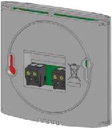


52 D Installation GB Installation F Installation E Instalación I Installazione P instalação NL installatie FIN Asennus SE Installation N Installasjon 1 2 t C ~1,20M Volt free connection Min 20cm Max 1mm² 2 wires + NTC 10k (25 C) 3 80 mm 83mm 27mm 60mm PPLIMP09460Aa
53 264
54 PPLIMP12569Aa 265 rev : 5/01/2012
 or ( ).")

55 How to accede it on the DP version Press 10 sec on the key In order to enter in the menu, select and valid the OFF mode ( ), then press on the escape key during 10 seconds, the following display with the first parameter must be appears: - Once you entered in the menu, go to the parameter which you want change by using the keys ( ) or ( ). - Use the keys (+) or (-) to edit and modify and confirm by pushing the (OK) key. - To leave the parameter menu, go to the parameter End and press the (OK) key. Note: You could reload one parameter to the default value if you press the escape key when the parameter value blinks. Parameters Installer s Advanced Menu N names Description of the parameter Factory value Other possibility cld For cooling Application 20 Mode --- Working mode For heating Hot application Rev The working mode can be done by the end user directly on the main menu. For reversible application The two followings parameters are only available on the wired version BT-DP NC NO 21 Out --- Type of output Normally Closed Normally Open (Output closed (Output opened when when demand) demand) 22 PumP --- Anti-lock-braking function for pump. When the pump hasn t worked on a particular day, start it up for one minute each day Yes Function activated No Function deactivated
56 FLR Floor sensor regulation 23 REGU --- Selection of the sensor used for the regulation. Internal ambient AIR sensor FL.L Air regulation with floor limitation possibilities (see parameters 26&27) 24 AirS --- View of the measured values of the ambient sensor.._ amb External ambient sensor 25 OUTS --- View of the measured values of the floor (external) sensor.._ 26 FL.Lo --- Lower limit of the floor temperature. The lower limitation is not no used From 5 C to FL.Hi no 27 FL.Hi --- Upper limit of the floor temperature. The upper limitation is not used Reg 28 Type --- Selection of regulation type 29 tcy HYSt --- Only available if the parameter 28 is set on reg value. Selection of the proportional band duration in minutes (cycle duration) Only available if the parameter 28 is set on HySt value. Selection of the hysteresis value in C Proportional band (PWM) 10 Ideal value for all Electrical floors heating application. 30 t.on Minimal starting time in minutes t.off Minimal resting time between 2 heating cycles in minutes 32 Bp Cp Value of the proportional band in C Note: If the value of proportional band is too big the system reactivity will be slower and could affect the steps of the program. Compensating value of the regulation This value will need to be modified only if the thermostat is perturbed by the heating element. Generally never the case with electrical floor heating. From FL.Lo to 37 C hys Hysteresis (On/Off) You could increase this value if the thermostat is used for other heating application (Oil Boiler...) Ideal value for all Electrical floors heating application Adjustable 0 to T cy/2 Adjustable 0 to T cy/2 Adjustable 1 to 6.0 A well insulated house «1.5 C» A not insulated house «4 C» Adjustable 0 to 14.0 Increase this value if the thermostat is too close to the heating source. 34 Clr EEp All parameters will be reloaded with the factory value. Press on the (OK) key during few seconds. 35 End To exit the installer s menu Press on the (OK) to exit.
Programmable Room Thermostat. User Guide UFHPROGB & UFHPROGRFB
 Programmable Room Thermostat User Guide UFHPROGB & UFHPROGRFB Overview The Programmable Room Thermostats Range (UFHPROGB & UFHPROGRFB) provides time and temperature control for a space of up to 40m 2.
2 Zone Time Clock. User Guide UFHTIME2B
 2 Zone Time Clock User Guide UFHTIME2B Overview The 2 Zone Time Clock is designed to work with the Dial Thermostat (UFHDIALB) to provide time control per manifold. Time clock also has 1 other zone which
OPERATION MANUAL. Room thermostat EKRTW
 OPERATION MANUAL 1 1 2 3 1 2 4 1 2 1 2 3 4 5 6 7 8 11 12 13 14 9 10 15 16 17 18 19 20 21 22 23 2 WARNINGS Never let the thermostat get wet, this may cause an electric shock or fire. Never press the buttons
7-day room temperature controller
 s 2 205 7-day room temperature controller Heating or cooling applications REV24.. Mains-independent, battery-operated room temperature controller featuring user-friendly operation, easy-to-read display
Weekday / weekend room temperature controller
 s 2 203 Weekday / weekend room temperature controller Heating applications REV17.. Mains-independent, battery-operated room temperature controller featuring user-friendly operation, easy-to-read display
7-day room temperature controller
 s 2 208 7-day room temperature controller Heating applications REV34.. Mains-independent, battery-operated room temperature controller featuring user-friendly operation, easy-to-read display and large
WavePRO Wireless Programmable T2500 Thermostat & R2500 Receiver OPERATING MANUAL. Model K
 WavePRO Wireless Programmable T2500 Thermostat & R2500 Receiver OPERATING MANUAL Model K2500-001 1 THE PECO WAVEPRO WIRELESS SYSTEM Thank you for choosing the PECO WavePRO TM Wireless System (Model K2500-001).
Weekday / weekend room temperature controller
 s 2 203 Weekday / weekend room temperature controller Heating applications REV17.. Mains-independent, battery-operated room temperature controller featuring user-friendly operation, easy-to-read display
RAMSES D GB F NL. Installation and operating instructions Room thermostat. RAMSES 832 top2
 309 358 04 RAMSES RAMSES 811 top2 RAMSES 831 top2 811 9 132 831 9 132 RAMSES 812 top2 RAMSES 832 top2 812 0 132 832 0 132 GB Installation and operating instructions Room thermostat D GB F E I NL RAMSES
Operating instructions for RAMSES 811 top2_812 top2 and RAMSES 831 top2_832 top2
 Operating instructions for RAMSES 811 top2_812 top2 and RAMSES 831 top2_832 top2 Dear client, if you have the newer device, please use page 1 to 33 RAMSES RAMSES 811 top2 RAMSES 831 top2 8119132 8319132
Model: Available in : Sapphire Black and Glacier White
 Model: Available in : Sapphire Black and Glacier White 1 Table of Contents Product Image 1 Locking/Unlocking the SmartStat 20 Table of Contents 2 Standby/Away Mode 21 What is a Programmable Room Thermostat?
Model: Available in : Sapphire Black and Glacier White
 1 Model: Available in : Sapphire Black and Glacier White 1 Table of Contents Product Image 1 Locking/Unlocking the SmartStat 20 23 Table of Contents 2 Standby/Away Mode Mode 21 24 What is a Programmable
Temperature control unit
 Temperature control unit 5739 18/19 Installation manual Part. U3582A - 12/08-01 PC Contents 1 - Introduction 5 1.1 - Warnings and tips 5 1.2 - Contents of package 5 2 - Description of the Control unit
Digital Room Thermostat for Underfloor Heating Applications
 ERT50 230v Digital Room Thermostat for Underfloor Heating Applications Instruction Manual Model No ERT50 230v PRODUCT COMPLIANCE This product complies with the essential requirements of the following EC
Dryer. M720 Programming and Operation Manual. July 15, 2015 Revision 1.51
 Dryer M720 Programming and Operation Manual July 15, 2015 Revision 1.51 Contents 1 Important Safety Information 1 1.1 FOR YOUR SAFETY - CAUTION!............................. 1 2 Control Overview 2 2.1
Functions. Technical Data. Wireless Room Thermostat
 This surface-mounted radio thermostat has been developed to be able to switch electric and conventional heating systems on and off using a set temperature and time. Functions Large display can be clearly
UC102 basic version with display and knob UC102BL version with display, knob and backlight UC102DK version without knob and display
 UC102 Communicative heating controller Summary UC102 is a communicative room heating controller with two inputs and one PWM output for control of a radiator or electrical heater. It can work autonomously,
Operation 6035 ENGLISH PROG MENU
 Operation 6035 PROG MENU ENGLISH Operation 6035 Program button Time of day Day Time Slot Current Room Temperature Target Temperature Menu button PROG MENU FAN AUTO ON COOL OFF HEAT Fan Switch Touch Screen
Operation Guide CT101
 Operation Guide CT101 PG 1 The CT101 communicating Z-Wave thermostat operates via a high-quality, easy-to-use touch screen. To set or adjust your CT101, simply touch your finger firmly to the screen. The
Model: EP210. Dual channel programmable controller. Installation Manual
 Model: EP210 Dual channel programmable controller Installation Manual Contents Introduction... 3 Product Compliance... 4 Safety Information... 4 Box content... 4 Features... 5 Installation... 5 Button
ERT50T Triac Noiseless Digital Room Thermostat for Underfloor Heating Applications
 ERT50T Triac Noiseless Digital Room Thermostat for Underfloor Heating Applications Instruction Manual Model No ERT50T Triac 2 PRODUCT COMPLIANCE This product complies with the essential requirements of
The UP and DOWN buttons will toggle or scroll through the options in each section.
 TECHNICAL BULLETIN: MWR-WE10, MWR-WE10N, MWR-WE11N Page 1 of 10 Throughout the scheduling process, the LEFT and RIGHT buttons will move forward and backward through each section of settings The UP and
RS Stock No Instruction Manual RS Input Data Logging Thermometer
 RS Stock No. 730-0458 Instruction Manual RS-1384 4 Input Data Logging Thermometer EN FR IT DE ES TABLE OF CONTENTS / EN TITLE TABLE OF CONTENTS PAGE 1. INTRODUCTION FEATURE... 1 2. SPECIFICATIONS... 2
Digital Room Thermostat
 Salus RT500 Manual 002:89 23/11/10 11:06 Page 1 Digital Room Thermostat Instruction Manual Model No RT500 2 Salus RT500 Manual 002:89 23/11/10 11:06 Page 2 PRODUCT COMPLIANCE This product complies with
S-Series Digital Thermostat
 Salus ST620 Manual 140x140 Finish:Layout 1 29/4/10 13:11 Page 1 S-Series Digital Thermostat Model No ST620 Instruction Manual Salus ST620 Manual 140x140 Finish:Layout 1 29/4/10 13:11 Page 2 2 Salus ST620
7-day room temperature controller
 s 2 205 7-day room temperature controller Heating or cooling applications REV24.. Use Mains-independent, battery-operated room temperature controller featuring user-friendly operation, easy-to-read display
Operation Guide CT32 ENGLISH
 Operation Guide CT32 The CT32 communicating thermostat operates via a high-quality, easy-to-use touch screen. To set or adjust your CT32, simply touch your finger firmly to the screen. The screen will
V0STAT51P-2 Programmable Wired Controller
 PRODUCT SPECIFICATIONS VARIABLE REFRIGERANT FLOW SYSTEMS VRF V0STAT51P-2 Programmable Wired Controller Bulletin No. 210766 March 2016 Grouping - Controller can control up to 16 indoor units on the same
SD1. Differential Controller. Operating and Installation Instructions F2 72.3
 SD1 Differential Controller Operating and Installation Instructions F2 72.3 i Please follow the safety information and read these Instructions carefully before putting the system into operation. Safety
FP735Si Electronic 3-Channel Full Programmer for Heating and Hot Water with Service Interval Timer. Installation Guide MAKING MODERN LIVING POSSIBLE
 MAKING MODERN LIVING POSSIBLE FP735Si Electronic 3-Channel Full Programmer for Heating and Hot Water with Service Interval Timer Danfoss Heating Installation Guide For a large print version of these instructions
REMOTE CONTROL INSTALLATION & OPERATING INSTRUCTIONS
 North American Version REMOTE CONTROL INSTALLATION & OPERATING INSTRUCTIONS Copyright 2009, FPI Fireplace Products International Ltd. All rights reserved. 918-290e 09/22/09 The FireGenie TM Remote Control
Programmable(5+1+1)Touch Screen LCD Wired Thermostat. General. Features. Operating Algorithm
Touch Screen LCD Wired Thermostat. General. Features. Operating Algorithm") Programmable(5+1+1)Touch Screen LCD Wired Thermoat General Front View Back View HTW-91-410 series ermoat is widely used in ese environment like Homes, Residential buildings, Schools, Offices and etc. to
Programmable(5+1+1)Touch Screen LCD Wired Thermoat General Front View Back View HTW-91-410 series ermoat is widely used in ese environment like Homes, Residential buildings, Schools, Offices and etc. to
S-Series Digital Thermostat
 S-Series Digital Thermostat Instruction Manual Model No ST620/ST620PB 2 PRODUCT COMPLIANCE This product complies with the essential requirements of the following EC Directives: Electro-Magnetic Compatibility
24-hour room temperature controller
 s 2 201 24-hour room temperature controller Heating applications REV13.. Use Mains-independent, battery-operated room temperature controller featuring user-friendly operation, easy-to-read display and
Operation Guide CT100
 Operation Guide CT100 PG 1 The CT100 communicating Z-Wave thermostat operates via a high-quality, easy-to-use touch screen. To set or adjust your CT100, simply touch your finger firmly to the screen. The
ADVANCED REMOTE CONTROL
 ADVANCED REMOTE CONTROL (SUITS IP28) INSTALLATION & OPERATING INSTRUCTIONS 918-962 12/07/10 The Advanced Remote Control is tested safe when installed in accordance with this installation manual. It is
2 Table of Contents 1. TABLE OF CONTENTS. 1. Table of Contents Introduction Wiring Diagram Terminals Review...
 TPR-6 Temperature Protection Relay Instruction Manual Ver. June 1 st 2010 2 Table of Contents 1. TABLE OF CONTENTS 1. Table of Contents... 2 2. Introduction... 3 3. Wiring Diagram... 5 4. Terminals Review...
RCF-230CTD. Room controller for fan-coil applications with outputs for two thermal or one 3-position actuator or function for an electric heater
 revision 03 2012 RCF-230CTD Room controller for fan-coil applications with outputs for two thermal or one 3-position actuator or function for an electric heater RCF-230CTD is a room controller intended
RS Stock No Instruction Manual RS Input Data Logging Thermometer
 RS Stock No. 730-0458 Instruction Manual RS-1384 4 Input Data Logging Thermometer EN FR IT DE ES TABLE OF CONTENTS / EN TITLE TABLE OF CONTENTS PAGE 1. INTRODUCTION FEATURE... 1 2. SPECIFICATIONS... 2
HDT-318 Thermo-Hygrometer with Data Logger. (Air Humidity/Temperature) Instruction Manual
 Instruction Manual") HDT-318 Thermo-Hygrometer with Data Logger (Air Humidity/Temperature) Instruction Manual CONTENTS 1. SAFETY INFORMATION... 2 2. GENERAL DESCRIPTION... 2 3. FEATURES... 2 4. SPECIFICATIONS... 3 5. SYMBOL
HDT-318 Thermo-Hygrometer with Data Logger (Air Humidity/Temperature) Instruction Manual CONTENTS 1. SAFETY INFORMATION... 2 2. GENERAL DESCRIPTION... 2 3. FEATURES... 2 4. SPECIFICATIONS... 3 5. SYMBOL
ST-292 User s manual. User manual ST-292 v1-3
 ST-292 User s manual User manual ST-292 v1-3 1 TECH I. Safety Before using the device for the first time the user should read the following regulations carefully. Not obeying the rules included in this
Communicative controller for VAV systems
 FCR015 Communicative controller for VAV systems Summary FCR015 is a communicative controller for heating and cooling panels and a VAV (variable air volume) damper. It measures temperature and CO 2 concentration
OPERATION INSTRUCTIONS
 2018 Lennox Industries Inc. Dallas, Texas, USA OPERATION INSTRUCTIONS V0STAT52 Wireless Indoor Unit Controller CONTROLS 507459-04 05/2018 This manual must be left with the owner for future reference. IMPORTANT
PT712-EI FOR FLOOR HEATING DIGITAL THERMOSTAT
 DIGITAL THERMOSTAT PT712-EI FOR FLOOR HEATING including external sensor backup in case of voltage failure > 100 hours direct installation on junction box well-arranged backlit display VENUS switch design
Model: Touchpad (TFT) Model: TFT
 Model: TFT") Model: Touchpad (TFT) Model: TFT 1 Model: Touchpad TFT Table of Contents Set-Up Product Image Table of Contents Installation Procedure Initial Setup Setting the Clock LCD Display My System Locking the
Model: Touchpad (TFT) Model: TFT 1 Model: Touchpad TFT Table of Contents Set-Up Product Image Table of Contents Installation Procedure Initial Setup Setting the Clock LCD Display My System Locking the
RVL470. Heating controller. G2522en. Installation Instructions. 1 Installation. 2 Commissioning Wall mounting DIN rail mounting
 G2522en Heating controller Installation Instructions RVL470 1 Installation 1.1 Place of installation In a dry room, e.g. the boiler room Mounting choices: In a control panel (on the inner wall or on a
Programmable(5+1+1)Touch Screen LCD Wireless Thermostat. General. Features. Operating Algorithm
Touch Screen LCD Wireless Thermostat. General. Features. Operating Algorithm") Programmable(5+1+1)Touch Screen LCD Wireless Thermoat General Controlling Panel Receiver HTW-91-WT410 series ermoat is widely used in ese environment like Homes, Residential buildings, Schools, Offices
Programmable(5+1+1)Touch Screen LCD Wireless Thermoat General Controlling Panel Receiver HTW-91-WT410 series ermoat is widely used in ese environment like Homes, Residential buildings, Schools, Offices
WEEKLY PROGRAMMABLE THERMOSTAT BACKLIGHTED TOUCH SCREEN CH150TS
 WEEKLY PROGRAMMABLE THERMOSTAT BACKLIGHTED TOUCH SCREEN CH150TS INDEX Introduction...3 Controls and indications...4 Controls...4 Indications...5 User manual...6 Setting the date and time...6 Summer/Winter
Quick Start Installation and User Manual
 1 Quick Start Installation and User Manual Contents 1. Overview 2. Technical Specifications 3. Installation Mounting Electrical Installation Clamp Installation Wiring Diagrams 4. Installation Settings
Model P4470 Save A Watt Operation Manual
 Model P4470 Save A Watt Operation Manual Thank you for purchasing the P4470 Save A Watt. This operating manual will provide an overview of the product, safety instructions, a quick guide to operation,
REMOTE CONTROL OPERATING INSTRUCTIONS
 REMOTE CONTROL OPERATING INSTRUCTIONS 918-582a 07/11/06 Copyright 2006, FPI Fireplace Products International Ltd. All rights reserved. FPI FireWizard TM Remote Control Manual Page 1 WARNING Shock Hazard
Select 107 XLS User Instructions
 Select 107 XLS User Instructions A timeswitch allows you to set On and Off time periods. The timeswitch will allow you to set the On and Off time periods for either Hot water or Central heating to suit
Semi flush-mounted room temperature controllers with LCD
 s 3 077 RDD310 RDE410 Semi flush-mounted room temperature controllers with LCD For heating systems RDD310 RDE410 RDD310 and RDE410 features: Operating voltage AC 230 V 2-position control with On / Off
SOLARIMMERSION IV Advanced Installation Manual v1.9
 SOLARIMMERSION IV Advanced Installation Manual v1.9 1 Contents 1. Overview 2. Technical Specifications 3. Installation Mounting Electrical Installation Clamp Installation Wiring Diagrams 4. Installation
MAXDTC-BT Family User Manual
 MAXDTC-BT Family User Manual Description The MAXDTC-BT is a fully programmable industrial temperature controller. The controller is configurable and monitorable thru a Bluetooth connection from your Android
Semi flush-mounted room temperature controllers with LCD
 s 3 077 RDD310 RDE410 Semi flush-mounted room temperature controllers with LCD For heating systems RDD310 RDE410 RDD310 and RDE410 features: Operating voltage AC 230 V 2-position control with On / Off
Owner s Manual RBC-AX32U(W)-E RBC-AX32U(WS)-E AIR CONDITIONER (SPLIT TYPE) Wireless remote controller kit. Model name: English.
-E RBC-AX32U(WS)-E AIR CONDITIONER (SPLIT TYPE) Wireless remote controller kit. Model name: English.") AIR CDITIER (SPLIT TYPE) Owner s Manual Wireless remote controller kit Model name: RBC-AX3U(W)-E RBC-AX3U(WS)-E Generic model name RBC-AX3U(W)-E Wireless remote controller model name WH-LSE Signal receiving
AIR CDITIER (SPLIT TYPE) Owner s Manual Wireless remote controller kit Model name: RBC-AX3U(W)-E RBC-AX3U(WS)-E Generic model name RBC-AX3U(W)-E Wireless remote controller model name WH-LSE Signal receiving
D GB F NL I E P. Overview per day of the programmed switching. Channel statuses are displayed ON / OFF
 D GB F NL I E P 310 783 03 TR 610 top TERMINA 1-channel 7 day timers According to version preprogrammed with the current time and summer/ winter norm time Safety Information The connection and installation
LCD LCDS LCDRI CONTROLLER OPERATING MANUAL
 This manual contains important safety information about installation and use of this equipment. Ignoring this information could result in injuries or damages. It is strictly forbidden to use this equipment
ZONETOUCH DAMPER CONTROL SYSTEM Operation Manual
 ZONETOUCH DAMPER CONTROL SYSTEM Operation Manual www.zonemaster.com.au www.polyaire.com.au 2012 Polyaire Pty Ltd TABLE OF CONTENTS 1) Features 2 2) Wall Controller Layout (Touchpad) 2 3) Manual On/Off
User Guide. Multipipe Units CMAA / RTMA CNT-SVU004B-GB
 User Guide Multipipe Units CMAA / RTMA CNT-SVU004B-GB USER GUIDE WARNING Supply the unit at least 24 hours before the initial startup to heat the compressor oil. In conditions of low water temperature,
Smart Touch Thermostat Colour Touchscreen Thermostat
 OBSMART Smart Touch Thermostat Colour Touchscreen Thermostat INTRODUCTION Orbry Smart Touch Thermostat The Orbry Smart Touch Thermostat is a digital thermostat, which is designed for electric underfloor
HH-521BT 4-Channel Thermocouple Data Logger (with Bluetooth) (Types K, J, T, N, E, R, S) Instruction Manual
 (Types K, J, T, N, E, R, S) Instruction Manual") HH-521BT 4-Channel Thermocouple Data Logger (with Bluetooth) (Types K, J, T, N, E, R, S) Instruction Manual CONTENTS 1. GENERAL DESCRIPTION... 2 2. SAFETY INFORMATION... 2 3. FEATURES... 2 4. SPECIFICATIONS...
HH-521BT 4-Channel Thermocouple Data Logger (with Bluetooth) (Types K, J, T, N, E, R, S) Instruction Manual CONTENTS 1. GENERAL DESCRIPTION... 2 2. SAFETY INFORMATION... 2 3. FEATURES... 2 4. SPECIFICATIONS...
HI HI N HI HI
 Instruction Manual HI 935005 - HI 935005N HI 935002 - HI 935009 Portable K-Thermocouple Thermometers www.hannainst.com These Instruments are in Compliance with the CE Directives Dear Customer, Thank you
Room Temperature Controller with 7-Day Time Switch, LCD and opt. Remote Temperature Sensor
 3 036 Room emperature Controller with 7-Day ime Switch, LCD and opt Remote emperature Sensor for heating systems RDE201 2-position control with ON/OFF output for heating Operating modes: normal operation
Temperature controller Ducted systems
 2 725 Temperature controller Ducted systems Standard model without zoning functions RRV851 Multifunctional controller used for central control of ducted HVAC systems in combination with a QAX850 master
P4472 Save A Watt HD Operation Manual
 P4472 Save A Watt HD Operation Manual Thank you for purchasing the P4472 Save A Watt HD. This operating manual will provide an overview of the product, safety instructions, a quick guide to operation,
Master room unit for RRV controllers
 2 722 Master room unit for RRV controllers 2 wire bus connection QAX850 Multifunctional, digital room unit for installer and end-user interface with RRV controllers. Use Use Application Room unit in combination
User Guide. For controller on CXAO / RTXB heat pumps CGCM / CXCM 2 circuit units. CNT-SVU005C-GB Original instructions
 User Guide For controller on CXAO / RTXB heat pumps CGCM / CXCM 2 circuit units CNT-SVU005C-GB Original instructions Table of contents Advanced electronics... 3 Technical Specifications... 4 Display description...
CENTER 521 INSTRUCTION MANUAL 4-Channel Thermocouple Data Logger (with Bluetooth) (Types K, J, T, N, E, R, S)
 (Types K, J, T, N, E, R, S)") CENTER 521 INSTRUCTION MANUAL 4-Channel Thermocouple Data Logger (with Bluetooth) (Types K, J, T, N, E, R, S) CONTENTS 1. GENERAL DESCRIPTION... 1 2. SAFETY INFORMATION... 2 3. FEATURES... 2 4. SPECIFICATIONS...
CENTER 521 INSTRUCTION MANUAL 4-Channel Thermocouple Data Logger (with Bluetooth) (Types K, J, T, N, E, R, S) CONTENTS 1. GENERAL DESCRIPTION... 1 2. SAFETY INFORMATION... 2 3. FEATURES... 2 4. SPECIFICATIONS...
RCF-230CAD. Communicating room controller for fan-coil applications with two analogue V DC outputs
 revision 01 2015 RCF-230CAD Communicating room controller for fan-coil applications with two analogue 0...10 V DC outputs RCF-230CAD intended to control heating and/or cooling in 2- or 4-pipe installations.
CDR-RH Room CO 2, Temperature and Humidity Sensors (Controllers)
") Product sheet SN1.401 Type CDR-RH CDR-RH Room CO 2, Temperature and Humidity Sensors (Controllers) CDR-RH sensors are designed to detect carbon dioxide concentration, relative humidity and temperature
Product sheet SN1.401 Type CDR-RH CDR-RH Room CO 2, Temperature and Humidity Sensors (Controllers) CDR-RH sensors are designed to detect carbon dioxide concentration, relative humidity and temperature
7 Day Digital Programmer 2 Channel Surface Mount
 7 Day Digital Programmer 2 Channel Surface Mount Model: TRT036N Installation & Operating Instructions 1. General Information These instructions should be read carefully and retained for further reference
ZEITSCHALTUHR TIMER SWITCH TIJDSCHAKELKLOK KOPPLINGSUR RELOJ TEMPORIZADOR IDŐZÍTŐ KAPCSOLÓ ΧΡΟΝΟΔΙΑΚΟΠΤΗΣ DZ 20-A V2
 DZ 20-A V2 ZEITSCHALTUHR Bedienungs- und Sicherheitshinweise TIJDSCHAKELKLOK Bedienings- en veiligheidsinstructies TIMER SWITCH Operation and Safety Notes KOPPLINGSUR Bruksanvisning och säkerhetsanvisningar
User Manual. Thermocouple Datalogging Thermometer. Model EA15
 User Manual Thermocouple Datalogging Thermometer Seven (7) Thermocouple input types K, J, T, E, R, S, N Dual thermocouple Input with PC Interface Model EA15 Additional User Manual Translations available
Model FP700 Owner s Instructions
 The benefits of owning a Freedom Advantage Thermostat Large easy to read backlit display Selectable programming modes: 5-2, 5-1-1 or 7 day Manufactured by the makers of ACCUSTAT controls ServiceWatch for
TP5000 Si Range Electronic 5/2 day programmable room thermostat Mains, Battery and RF versions Installation and User Instructions
 TP5000 Si Range Electronic 5/2 day programmable room thermostat Mains, Battery and RF versions Certification Mark GB Installation and User Instructions GB Index Index 3-14 Product Specification 3 Installation
Model: TM-1 / TM1-N. 1 Time Clock Series
 Model: TM-1 / TM1-N Model: TM-1 / TM1-N 1 Time Clock Series Table of Contents Product Image Table of Contents Installation Procedure LCD Display Operating Modes Setting the Operating Mode Setting the Clock
AMBIFLEX MF626 - USER GUIDE
 AMBIFLEX MF626 - USER GUIDE CONTENTS Page No Product Overview 2 Features 3 Standby Display 4 User Facilities 5 Status Display Mode 6 Measured Temperatures 6 Time Channel Information 7 What is happening
3000 CONTROLLER TRAINING MANUAL. April 26, 2012 Software Version
 3000 CONTROLLER TRAINING MANUAL April 26, 2012 Software Version 1.59.03 Contents 3000 CONTROLLER USER GUIDE Quick Reference: Using the 3000... 3 Menu Summary Tree... 6 Main Menu: Programming your Fryer...
Configuring Cisco Access Policies
 CHAPTER 11 This chapter describes how to create the Cisco Access Policies assigned to badge holders that define which doors they can access, and the dates and times of that access. Once created, access
U-FLASH Setup Guide U-FLASH.
 U-FLASH Setup Guide Thank you for purchasing the U-FLASH. This guide will assist you in the setup of the system. You can call for FREE technical support to get help anytime at 757-258-0910. Please note,
DFx Series 1e Controller Instruction Manual
 DFx Series 1e Controller Instruction Manual www.dfxtech.co.uk/cooler 1. Welcome..... 3 2. Series 1e Schematic...3 3. Important Information........ 3 4. Parts List..... 4 5. Specifications..... 5 6. Key
3700 SERIES USER MANUAL
 SAFETY GUIDE This manual contains the precautions necessary to ensure your personal safety as well as for protection for the products and the connected equipment. These precautions are highlighted with
USER GUIDE. Differential Thermometer Datalogger. Model HD200
 USER GUIDE Differential Thermometer Datalogger Model HD200 Introduction Congratulations on your purchase of the Extech HD200 Differential Thermometer Datalogger. The HD200 supports differential temperature
RoomMaster ABR-2. Commissioning
 Commissioning Content GENERAL Locking of operating mode keys...3 Control panel...3 Function of operating mode keys, operating menu...3 Activation of setting keys...4 Locking of setting keys...4 Setting
Operating instructions
 SOLARTHERMIE - SOLAR THERMAL - SOLAR TÉRMICO - SOLAIRE THERMIQUE Operating instructions Temperature Difference Controller 6 inputs / outputs EN 714.884 08.15 ZO 714.884 08.15 1 Case overview Operating
LLR-MOD Modbus Light Level and Occupancy Sensor
 Product sheet SN1.418 Type LLR-MOD LLR-MOD Modbus Light Level and Occupancy Sensor The LLR-MOD sensors are designed to measure Light Level (LUX) in the room spaces and have built-in RS485 Modbus communication
REMOTE CONTROLLER CS244-R OWNER S MANUAL
 OWNER S MANUAL REMOTE CONTROLLER Please read this Owner's Manual carefully before operation. Save this manual in a safe place for future reference. CS-R . After setting the TIMER, there will be a one-half
HygroLog HL20 and HL21 Data Logger. User Guide
 Page 1 of 17 HygroLog HL20 and HL21 Data Logger Page 2 of 17 Table of contents: 1. Overview... 3 1.1 General... 3 2. General description... 4 2.1 Models... 4 2.2 Required accessories... 4 2.3 Batteries...
EC700. Pulses concentrator. User instructions
 EC700 Pulses concentrator User instructions Contents Hazards and warning... 3 Initial checks... 3 Introduction... 4 Jbus/Modbus Communication... 5 Installation... 6 Configuration... 9 Use... 9 Programming...
Microprocessor based Temperature / CO2 Controller c/w 365 Day Time Switch & Modbus Communication.
 HTC-DIGITAL-LCD Microprocessor based Temperature / CO2 Controller c/w 365 Day Time Switch & Modbus Communication. Features Use Australian Made and designed LCD 2 X 16 Character Backlit Display Five Programmable
Wall mounted units. Please read carefully and thoroughly this manual before operating this unit and save it in a safe place for future reference.
 OWNERS' MANUAL REMOTE CONTROLLER Wall mounted units Please read carefully and thoroughly this manual before operating this unit and save it in a safe place for future reference. Warning. Be sure there
idigit CONTROL INSTALLER MANUAL Digital thermostat for fan coil units Rev100
 idigit CONTROL Digital thermostat for fan coil units INSTALLER MANUAL Termostato digital para ventiladores-convectores Thank you for trusting the Hitecsa Products. Our company has been offering the market
DS Type: MAXIM III Controller
 DS 10.03 Models: MAX3ELD MAX3ELN MAX3NLD MAX3NLN Overview The Innotech MAXIM III Controller is a state of the art digital processing system that has the capability of controlling various types of industrial,
ON/OFF HUMIDIFIER CONTROL (ROOM 0R DUCT SENSOR) WITH OUTDOOR TEMPERATURE RESET OVERVIEW WALL CONTROLLER INSTALLATION (TCY-BH-T-U)
 WITH OUTDOOR TEMPERATURE RESET OVERVIEW WALL CONTROLLER INSTALLATION (TCY-BH-T-U)") (ROOM 0R DUCT SENSOR) WITH OUTDOOR TEMPERATURE RESET TCY-BH-T-U Wall controller with sensor TDC-BH-T-U Duct controller with sensor SOA-Tn10 Outdoor temperature sensor (Optional) OVERVIEW For wall applications
(ROOM 0R DUCT SENSOR) WITH OUTDOOR TEMPERATURE RESET TCY-BH-T-U Wall controller with sensor TDC-BH-T-U Duct controller with sensor SOA-Tn10 Outdoor temperature sensor (Optional) OVERVIEW For wall applications
Viconics VT76x6W Water-source Heat Pump Controllers Engineering Guide Specification
 Viconics VT76x6W Water-source Heat Pump Controllers Engineering Guide Specification General The VT76xxW series is designed for single-stage and multi-stage control of water source heat pumps with dedicated
User Guide. FreeCool : Free Cooling unit V1.1 ENGY-SVU001A-GB
 User Guide FreeCool : Free Cooling unit V1.1 ENGY-SVU001A-GB Table of Contents Introduction...3 General features...4 User interface...5 Top display area... 5 Bottom display area... 5 Main display area...
Owner s Manual. Digital Player Addendum. For Heat Siphon Swimming Pool Heat Pumps
 Made in Latrobe Since 1983 Pennsylvania U.S.A. Owner s Manual Digital Player Addendum For Heat Siphon Swimming Pool Heat Pumps Heating Only Models: Z250HP, Z375HP, Z575HP & Z700HP Z250HP50, Z375HP50, Z575HP50
ZCM-12, ZCM-12P/U TIME PROGRAMMER WEEK S, DOUBLE CHANNEL
 ZCM-12, ZCM-12P/U TIME PROGRAMMER WEEK S, DOUBLE CHANNEL INSTRUCTION MANUAL ZAMEL Sp. z o.o. ul. Zielona 27, 43-200 Pszczyna, Poland Tel. +48 (32) 210 46 65, Fax +48 (32) 210 80 04 www.zamelcet.com, e-mail: