IVP-3000 Series Multi-channel HD/SD Encoder REFERENCE GUIDE
|
|
|
- Isabella Perry
- 6 years ago
- Views:
Transcription


1 IVP-3000 Series Multi-channel HD/SD Encoder REFERENCE GUIDE
2 Revision History Issues of this Reference Guide are listed below: Version Date Mainboard Version Comments V /02/2016 V Updated to Version
3 Contents Contents Chapter 1 Introduction Introduction Front Panel Power USB Port Control port Main Display Indicator Lights Keypad Rear Panel... 8 Chapter 2 Installing the Equipment Read This First! Mounting and Ventilation Fixing and Rack Mounting Ventilation Module Introduction Chapter 3 Getting Started Introduction How to Connect Up the Unit How to Power Up the Unit How to Set the Unit IP Address Chapter 4 Front Panel Control Introduction Using the Front Panel Controls Keyboard Lock Power up... 15
4 Contents 4.3 Basic Operation Logic IP Settings HD Digital Encoder Module (HDE-420) SD Digital/Analog Encoder Module (SDE-420) IPASI Output I/O Module (IO-ASI-O) ASI I/O Module (IO-ASI) ASI In Setting ASI Out Setting Chapter 5 Web Control Using the Web Graphical User Interface Web browser configuration IVP-3000 Frame Setting Account Network Date & Time Update &Reboot Device Information Input Setting HD Digital Encoder Module (HDE-420/422) SD Digital/Analog Encoder Module (SDE-420) Multi-stream HD Digital Encoder Module (MHDE-420) ASI I/O Module (IO-ASI) TS Processor Setting R2TP Processor Setting Stream Port Setting Transport Streams Setting Ping Tools Software Upgrade Output Setting... 72
5 Contents IPASI Output I/O Module (IO-IPASI-O) ASI I/O Module Alarm Annex A - Specifications... 77
6 Introduction Chapter 1 Introduction 1.1 Introduction IVP-3000 is a broadcasting level multimedia processing platform. It adopts 1RU and a modular design with 6 slots in it. By installing different modules, it could realize the following various applications: satellite signals receiving, H.264/MPEG-2 HD/SD video encoding and decoding, CA or BISS descrambling, real-time transmission stream monitoring, program multiplexing, channel backup, etc. The IVP platform is based on CPCI architecture with power redundancy design and hot swapping functions. If one function module is out of order, the users only need to replace the corresponding function cards, the whole process no need to cut off the power, and other function modules will not be affected. The IVP-3000 Series Multi-channel HD/SD Encoder is based on IVP platform, adopting H.264 HD encoding module, H.264/MPEG-2 SD encoding module, ASI I/O module and IP I/O module, to achieve a multi-channel HD encoder with high flexibility, high density, high performance, high scalability and high reliability. The following is a summary of the features of IVP-3000 Series Multi-channel HD/SD Encoder: (1) High Level Performance Support H.264/MPEG-2 HD/SD encoding Support H.264 4:2:2 / 4:2:0 chroma encoding Support ASI redundant output Support IP redundant output to different target IP address Support 2 encoding latency mode: Standard latency: 730ms Low latency: 120ms (2) High Density Up to 5 channel HD encoding Up to 10 channel SD encoding
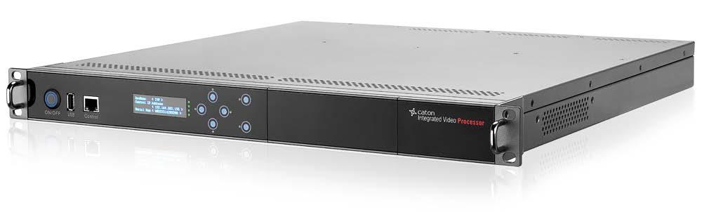
7 Introduction HD encoder support 4 channel stereo audio encoding (3) High Scalability Modular design with various modules, it could be configured with different module based on needs Upgrade through simply adding or replacing with new module to save the upgrading cost 1.2 Front Panel The front panel of the unit consists of a power, an USB Port, an Ethernet Control port, a main OLED display screen, four Indicator Lights and six touch buttons. Figure 1.1 Front Panel Power The ON/OFF button, after the device powered, press this button to start the device USB Port Mount USB flash disk to save or apply the configuration file for disaster recovery Control port Ethernet control port for web control Main Display Control and status information is displayed on an OLED display Indicator Lights Front panel LEDs indicate system status (Top->Bottom): LED1.Power1 status: Green:OK; Red:Error;
 Chassis-R-H (Hot-Swap Redundancy Power) Figure 1.")
8 Introduction LED2.Power2 status: Green:OK; Red:Error; LED3.Temprature: Green:OK; Red:Over 50 ; LED4.Alarm:Green:No unread error messages;red:error encountered; Keypad Include up, down, left and right direction keys, as well as Enter and Esc button. 1.3 Rear Panel According to the power type of IVP-3000, the rear panel of IVP-3000 includes 2 types: 1) Chassis-R-H (Hot-Swap Redundancy Power) Figure 1.2 Chassis-R-H Rear Panel The Chassis-R-H rear panel consists of six slots (U1, U2, U3, L1, L2 and L3), 2 hot-plug power. You can insert different modules according to user needs. 2) Chassis-R (Internal Dual Redundancy Power) Figure 1.3 Chassis-R Rear Panel The Chassis-R rear panel of the unit consists of six slots (U1, U2, U3, L1, L2 and L3), Power Interface, Power Switch and Fan. You can insert different modules according to user needs. Note: Keep the vent clear to ensure the rejection of heat.
9 Installing the Equipment Chapter 2 Installing the Equipment 2.1 Read This First! This Reference Guide is written for operators / users of the IVP It describes the unit s functions and operation. The Reference Guide is written to assist in the installation and day-to-day operation and care of the unit. Maintenance information requiring the covers to be removed is not included. 2.2 Mounting and Ventilation Fixing and Rack Mounting The equipment is designed for fixed use only and has been shipped with fixing brackets suitable for a standard 19-inch rack. When installed in a rack, it should be secured using the fixing brackets. In addition, support shelves must be used to reduce the weight on the brackets. Ensure it is firmly and safely located and it has an adequate free-flow of air. Slide the unit onto the chassis supports and affix to the rack by means of an M6 x 18 mm panhead screw in each corner. A freestanding unit should be installed on a secure horizontal surface where it is unlikely to be knocked or its connectors and leads disturbed Ventilation Side openings in the unit, as well as rear-mounted cooling fans, are provided for ventilation. They ensure reliable operation of the product and protect it from overheating. The openings of the fans must not be blocked or covered.


 Function:1 channel HD")
 Function: Multi-stream H.")
10 Installing the Equipment 2.3 Module Introduction The introduction of encoding module listed in the following tables. 422 HD Digital Encoder Module (HDE-422) 420 HD Digital Encoder Module (HDE-420) Function: 1 channel HD/SD 4:2:2/4:2:0 H.264 encoding Function: 1 channel HD/SD 4:2:0 H.264 encoding Interface: Interface: SD Digital/Analog Encoder Module (SDE-420) Function: 2 channel SD H.264/MPEG-2 encoding Multi-Stream HD Digital Encoder Module (MHDE-420) Function:1 channel HD encoding, 3 encoding stream output Interface: Interface: Multi-Channel H.264 Transcoder Module (MHDT-420) Function: Multi-stream H.264 HD/SD transcoding ASI I/O Module (IO-ASI) Function: 4 ASI input or output, support various pattern Interface: IPASI Output I/O Module (IO-IPASI-O) Multi-Protocol IP Transmitting Module (SMIP)


11 Installing the Equipment Function: Support IP output and 2 ASI output Function: Multi-Protocol IP Transmitting over Open Internet Interface: Interface:

12 Getting Started Chapter 3 Getting Started 3.1 Introduction Due to the number of different ways the IVP-3000 Series can be used, it is impossible to give precise setting up instructions for every possible working scenario. This chapter, therefore, gives general guidance and principles on how to power up and set up your unit for operation and describes the more common operations you will want to perform. For details of all Front Panel menus and controls, see Chapter 4, Front Panel Control. For details of all Web Graphical User Interface menus and controls, see Chapter 5, Web Control. 3.2 How to Connect Up the Unit See Chapter 2, installing the Equipment for all connector details. Figure 3.1 Equipment Connection Diagram To connect up the unit(s): Connect signal input connectors (for your input Transport Streams) to your local area network if IP/ASI inputs are to be used. Connect signal output connectors (for your output Transport Streams) to your local area network if IP/ASI outputs are to be used. Connect computer control connectors Web Control to your local area network. Both connectors are in the same subnet mask. Connect single or dual AC power connectors, depending on the option purchased, to the power supply. Connect your signal cables to/from your option cards, depending on which options are fitted to


13 Getting Started your unit, as required. 3.3 How to Power Up the Unit To power up the unit(s): With all signal and power cables connected as required, through equipment power supply. Wait for unit to initialize completely. 3.4 How to Set the Unit IP Address Setting the IP address of a unit is accomplished using the front panel menus. For a full description of these menus, see Chapter 4, Front Panel Control. To set the IP address of the unit(s): 1. Ensure the unit is fully powered up. 2. On the OLED front panel, using the touch button, go to the IVP-3000 Frame>IP Setting option. 3. Press Enter Button to select. 4. Using the touch button, set the IP address, subnet mask and gateway address. 5. Press the Enter button to save or Esc to discard the changes. Note:1. It may be necessary to set the IP address, gateway address and Virtual IP address to 0, and to set a subnet mask in order to allow the IP address to be changed. 2.IP Addresses on the unit must adhere to RFC3330 range of restrictions as listed in the following table of allocated IP addresses. 3.Make sure that the control network and data networks do not conflict. 3.5 How to Configure Ethernet Control Port The Base Chassis has control port that support IEEE BaseTX and 1000 BaseT protocols. Figure 3.2 Control Port
14 Getting Started The Ethernet control ports are used to connect the unit to a control computer for control through a web browser. Ethernet Control Port Parameters A single IP port is defined for all Ethernet control traffic to and from the chassis. The physical ports used for Ethernet control are by default the control Ethernet ports. The control ports can raise an alarm during abnormal operational conditions.
, wait for initialization to complete (approximately 2 minutes, depending on the number of options fitted in the chassis)before attempting to")
15 Front Panel Control Chapter 4 Front Panel Control 4.1 Introduction This chapter describes the features and options provided by the Front Panel menus for controlling the IVP Note: After powering up (see Chapter 3, Getting Started), wait for initialization to complete (approximately 2 minutes, depending on the number of options fitted in the chassis)before attempting to use the front panel menus and controls. 4.2 Using the Front Panel Controls The front panel of the unit consists of a power, an USB Port, an Ethernet Control port, a main OLED display screen, four Indicator Lights and six touch buttons. The unit can be controlled through the front touch buttons. Figure 4.1 IVP-3000 Front Panel Keyboard Lock The controls are locked after a time of inactivity. The keys can be unlocked by click,,, in turn, then in this sequence as instructed Unlocked on the front panel Power up Power up IVP-3000, OLED screen will display as follows:

16 Front Panel Control IVP Starting 0% Power on the device, the screen displays company logo. Dev Name < IVP > Control IP Address < > Serial Num < > After about 60s, the screen displays device status IVP Frame Input_U1_HD Enc Input_U2_SD Enc Output_L2_IP_ASI After click Enter button, the screen displays device setting tree. Figure 4.2 Booting Front Panel Display Process 4.3 Basic Operation Logic There are 6 buttons on the front panel. Figure 4.3 Front Panel Display,, Enter button ESC button Select parameters to watch or configure. Adjust configurable values in editable mode. Enter editable mode or navigate to a sub menu. Exit editable mode or go back to a parent menu. Users may need to unlock the front panel, and then refer to the menu structure of the front panel display, with the button to complete the device parameter settings, parameter queries and other operations.
17 Front Panel Control 4.4 IP Settings Figure 4.4 IP Settings Table 4.1 IP Settings Item Option Comment Frame IP Setting Local IP Net Mask Gateway <Custom> <Custom> <Custom> IP Settings of Device Control Port.
18 Front Panel Control 4.5 HD Digital Encoder Module (HDE-420) Figure 4.5 HDE-420 Settings Table 4.2 HDE-420 Settings
19 Front Panel Control Item Option Comment Encode Mode <H.264> SDI Video Source HDMI CBar Color Bar Video Settings Video Format 1080p p p i i i50 720p p60 720p50 480i i50 Video Bitrate <Custom> (Kbps) Video PID Audio Enable <Custom> Enable Disable Enable current audio channel Audio Source Audio Format <MPEG1> 96 Audio Settings Audio Bitrate Audio PID Audio Mode <Custom> <Stereo> TS ID <Custom> 0x0 to 0xFFFF Program Settings PCR PID <Custom> 0x20 to 0x1FFE PMT PID <Custom> 0x20 to 0x1FFE Service ID <Custom> 0x0 to 0xFFFF
20 Front Panel Control Service Name TS Bitrate <Custom> 500~65000 (Kbps) Status Status Input Source Input Format <Read Only> <Read Only> <Read Only>
21 Front Panel Control 4.6 SD Digital/Analog Encoder Module (SDE-420) Figure 4.6 SDE-420 Settings Table 4.3 SDE-420 Settings
22 Front Panel Control Item Option Comment Encode Mode Video Source H.264 MPEG2 SDI CVBS PAL Video Format NTSC/29.97 NTSC/30 720* * * * *576 PAL 352*576 Video Settings Video Resolution 352* * * * * * *480 NTSC 352* * * ~6000 H.264 Single-Channel Video Bitrate 250~15000 H.264 Twin-Channel 500~7000 MPEG-2 Single-Channel 500~15000 MPEG-2 Twin-Channel Video PID <Custom> Audio Source Enable Enable current audio channel Audio Settings Audio Format MPEG-1 Layer II AAC-LC HE-AAC V1 HE-AAC V2
23 Front Panel Control AC3 Bypass Audio Bitrate Audio PID Audio Mode <Custom> Dual-Mono Stereo TS ID <Custom> 0x0 to 0xFFFF Program Settings Service ID <Custom> 0x0 to 0xFFFF PCR PID <Custom> 0x20 to 0x1FFE PMT PID <Custom> 0x20 to 0x1FFE TS Bitrate <Custom> 500~20000 (Kbps) Status Ch1 Status Ch1 Input Ch2 Status Ch2 Input <Read Only> <Read Only> <Read Only> <Read Only>
24 Front Panel Control 4.7 IPASI Output I/O Module (IO-ASI-O) Figure 4.7 IO-IPASI-O Settings Table 4.4 IO-IPASI-O Settings Item Option Comment Enable ON OFF Enable using the current Ethernet port Stream Channel Dest IP <Custom> Destination IP address Dest Port <Custom> Destination IP port UDP Protocol RTP Transport Protocol Ser List Service ID to output Bitrate <Custom> Greater than the bitrate of selected service ASI Out Select the Source to output Status Status Speed <Read Only> <Read Only>
25 Front Panel Control Duplex <Read Only> 4.8 ASI I/O Module (IO-ASI) ASI In Setting Figure 4.8 IO-ASI Input Settings Table 4.5 IO-ASI Input Settings Item Option Comment Input ASI ASI 1 IN <Read Only> Display status of ASI 1 input ASI 2 IN <Read Only> Display status of ASI 2 input ASI Out Setting Figure 4.9 IO-ASI Output Settings Table 4.6 IO-ASI Output Settings Item Option Comment Input ASI ASI 1 OUT Select the source to output ASI 2 OUT Select the source to output
26 Chapter 5 Web Control 5.1 Using the Web Graphical User Interface The IVP-3000 is designed to be configured and controlled by its own web graphical user interface. The Graphical User Interface uses widget based architecture. This section describes the functions and elements. 5.2 Web browser configuration Use an Internet web browser running on a personal computer (PC) to take advantage of the remote setup capability. Below is the guide you need to follow: Prepare a computer with Internet web browser. Tips: IE version 8.0 or above Firefox version or above are highly recommended. Connect your PC to the management network interface of the device via Ethernet. Confirm computer IP address, make sure that the device and the computer in the same network segment Input the device IP address in the web browser, it will displays the Login page, as follows: Figure 5.1 Login

27 Type in the Account and Password to login. (Default Account: admin Default Password: ) 5.3 IVP-3000 Frame Setting When users get a successful user authentication at the IVP-3000 login prompt, the Home page appears as shown below. Figure 5.2 Home Home page displays the basic info of IVP-3000 device, including module, power, fan and temperature. It also includes real-time input/output statistics. to view status information of selected module. in Basic Settings bar to configure the basic settings of IVP-3000 device Account in Account bar to modify the password to login.
28 Figure 5.3 Account The password need to be in 6~16 characters (From A-Z, 0-9). to save the configuration. to refresh current page Network in Network bar to configure the device IP address. Figure 5.4 Network IP Address: Device IP Address setting. Subnet Mask: Net Mask setting. Gateway: Default Gateway setting.
29 User can also configure device IP through panel control, please refer to Chapter 4 for more info Date & Time in Date & Time bar to configure the date and time info of the device. Figure 5.5 Date & Time Mode: Enable/Disable NTP Server: Net Mask setting. Time Zone: Default Gateway setting. Synchronous: The cycle used to synchronous with NTP server Update &Reboot in Update & Reboot bar to update the main board or reboot the device. You may need to input the password again for verification.

30 Figure 5.6 Update & Reboot 1. Upgrade To upgrade the main board, click to select the upgrade package in PC and click to submit it. Figure 5.7 Confirm to confirm the upgrade.

31 Figure 5.8 Upgrade The upgrade will take about 5 minutes, please do not leave this page or power off. After the upgrade is finished, web will refresh automatically. 2. Reboot to reboot the device. Figure 5.9 Reboot
32 The reboot will take about 3 minutes, please do not leave this page or power off. After the reboot is finished, web will refresh automatically. 3. Factory Reset to recover to the default settings. Figure 5.10 Factory Reset The reset will take about 5 minutes, please do not leave this page or power off. After the reset is finished, web will refresh automatically.
33 5.3.5 Device Information in Device Information bar to view the basic info of device and modules, including Hardware Version(HW), Software Version(SW), FPGA Version, Serial Number etc. Figure 5.11 Device Information
34 5.4 Input Setting Inputs in main menu to open the Input Setting page HD Digital Encoder Module (HDE-420/422) in HD Low Encoder*1 bar to configure HDE-420 module. in HD SL Encoder*1 bar to configure HDE-422 module Settings Select Settings column to configure basic encoding settings of HDE-420/ Bitrate Setting Mode Figure 5.12 Setting Figure 5.13 Bitrate Setting Mode
35 Video ES Bitrate Auto: Video ES Bitrate cannot be editable and will be calculated automatically from TS Bitrate TS Bitrate Auto: TS Bitrate cannot be editable and will be calculated automatically from Video ES Bitrate Manual: Video ES Bitrate and TS Bitrate will be decided both by user. 2. Video Parameters Figure 5.14 Video Parameters Table 5.1 Video Parameters Item Option Comment Source Color Bar Black Field SDI HDMI Auto Internal Signal Internal Signal External Signal External Signal According to the input source format Video Parameters 1080p p p25 Format 1080i i i50 720p p60
36 720p50 480i i p/1080i Horizontal Size Entropy Latency CAVLC CABAC Regular Low Delay Super Low 720p 480i/576i Codec delay About 700ms Codec delay About 160ms Codec delay About 40ms(HDE-422 Only) Bitrate(Kbps) Main Profile High High 4:2:2 HDE-422 Only IP GOP Structure IBP IBBP Deblocking Filter ON OFF Loss of Input Color Bar Black Field None Automatically switch to ColorBar, With TS output Automatically switch to Black Field, With TS output No Video Encoding, With TS output

37 No TS Output No TS output Closed GOP GOP Mode Enable Disable Dynamic Constant Automatically adjust the GOP length according to the scene Constant GOP length GOP Num 1~30 Unit frame OFF Adaptive Low Pass Filter Weak Moderate Strong 3. Audio Parameters Figure 5.15 Audio Parameters Table5.2 Audio Parameters Item Option Comment Audio-X Enable On/Off on to enable current audio channel SDI-CH1/2 SDI-CH3/4 Audio Parameters Source SDI-CH5/6 SDI-CH7/8 HDMI-CH1/2 HDMI-CH3/4 HDMI-CH5/6
38 HDMI-CH7/8 AES-EBU 1KHz Format MPEG1 Layer-II AAC-LC Bitrate(Kbps) Coding Mode Loss of Input Dual Mono Stereo Mono L Mono R Mono Mix 1KHz Mute None Using The left channel data ofinput audiofor encoding Using The right channel data of input audiofor encoding Mix the left channel and right channel data for encoding Automatically switch to 1KHz Automatically switch to Mute audio No audio output ±500 Regular Latency Mode Delay(ms) ±100 Low Latency Mode ±0 Super Low Latency Mode (HDE-422 only) Gain Ctrl Disable Enable Disable Audio gain adjustment function Enable Audio gain adjustment function Loudness(LKFS) -30~0 Target loudness Gain(dB) -20~+20 Audio gain value Time Period 200~5000ms Time window used to control loudness ALC Ctrl Gate Bypass Enable -65~-40LKFS disable Audio ALC function Enable Audio ALC function Minimum threshold value of loudness calculation
39 4. Program Parameters Figure 5.16 Program Parameters Table 5.3 Program Parameters Item Option Comment Bitrate(Kbps) 500~65000 PSI/SI Parameters PMT PID PCR PID Video PID Audio1 PID Audio2 PID Transport ID Service ID Service Provider Audio1 PID Audio2 PID PMT Interval PCR Interval PAT Interval SDT Interval 0x20 to 0x1FFE 0x20 to 0x1FFE 0x20 to 0x1FFE 0x20 to 0x1FFE 0x20 to 0x1FFE 0x0 to 0xFFFF 0x0 to 0xFFFF <Custom> <Custom> 0x20 to 0x1FFE 0x20 to 0x1FFE 1~500ms 1~40ms 1~500ms 1~10000ms
40 5. BISS Settings Figure 5.17 BISS Settings BISS encryption settings for current encoding channel: BISS-0:None BISS decryption. BISS-1:BISS-1 decryption. Session Word should be 12 numbers. BISS-E:BISS-E decryption. Session Word should be 16 numbers. Inject ID should be 14 numbers. to save the configuration. to refresh current page. to save the configuration as a profile. User can apply this configuration to other HDE-420/422 module by uploading the profile Status Select Status column to view the encoding status and ALC status.
41 Figure 5.18 Status to refresh current page. to reboot HDE-420/422 module Profiles Select Profiles column to upload the configuration file. Figure 5.19 Profiles to select the configuration file in PC, click to upload the file to IVP Choose the configuration file in Profiles column and click to apply. User can also
42 load the Factory Default file to recover to the default settings Upgrade Select Upgrade column to upgrade HDE-420/422 software on web UI. Figure 5.20 Upgrade to select upgrade package in PC and click to upgrade. The upgrade will take about 5 minutes, please do not leave this page or power off.
43 5.4.2 SD Digital/Analog Encoder Module (SDE-420) in Encoder*2 bar to configure SDE-420 module. SDE-420 module support source*2 encoding, user can configure 2 encoders separately. Encoder1/Encoder2 bar to configure each encoder Settings Select Settings column to configure basic encoding settings of SDE Bitrate Setting Mode Figure 5.21 Setting Figure 5.22 Bitrate Setting Mode Video ES Bitrate Auto:
44 Video ES Bitrate cannot be editable and will be calculated automatically from TS Bitrate TS Bitrate Auto: TS Bitrate cannot be editable and will be calculated automatically from Video ES Bitrate Manual: Video ES Bitrate and TS Bitrate will be decided both by user. 2. Video Parameters Figure 5.23 Video Parameters Table 5.4 Video Parameters Item Option Comment Video Enable On/Off off to encode audio source only Source SDI CVBS PAL Format NTSC/29.97 Video Parameters NTSC/30 720* * * * *576 PAL Resolution 352* * * * *480 NTSC 640*480
45 544* * * * * ~6000 H.264 Single-Channel Video Bitrate 250~15000 H.264 Twin-Channel 500~7000 MPEG-2 Single-Channel 500~15000 MPEG-2 Twin-Channel Encoder Mode H.264 MPEG-2 to configure advanced video parameters. Figure 5.24 More Parameters Table 5.5 More Parameters Item Option Comment No IDRs More Parameters IDR Frequency Profile Every I Frame Every second I Frame Every third I Frame Main H.264 Baseline Level Automatic Level1.3 Level2.0 H.264/MPEG-2 H.264
46 Level2.1 Level2.2 Level3.0 Main MPEG-2 Closed GOP Open GOP Close GOP GOP Size 1 to 255 IP GOP Structure IBP IBBP VBI Capture VBI input in LSB VBI input in MSB Insert/extract all captions Insert/extract EIA608B field 1 and 2 Closed Captioning Insert/extract EIA608B field 1 Insert/extract EIA608B field 2 Insert/extract EIA608B CABAC Disable Enable Off Loop Filter Mode On Not across slice boundaries
47 3. Audio Parameters Figure 5.25 Audio Parameters Table5.6 Audio Parameters Item Option Comment SDI-Ch1/2 SDI-Ch3/4 Source SDI-Ch5/6 SDI-Ch7/8 Analog AES/EBU Sampling Rate(KHZ) 48 SDI or AES/EBU Source 32/44.1/48 Analog Source Audio Parameters Volume Format Coding Mode Level 0 Level 1 Level 2 Level 3 Level 4 MPEG-1 Layer II AAC-LC HE-AAC V1 HE-AAC V2 AC3 Bypass Dual-mono Stereo Mono L Mono R
48 Mono L/R Bitrate(kbps) Delay(ms) 0~ Program Parameters Figure 5.26 Program Parameters Table 5.7 Program Parameters Item Option Comment PSI/SI Bitrate(Kbps) 500~20000 Parameters Transport ID 0x0 to 0xFFFF
49 Service ID Service Provider PMT ID PCR ID Video PID Audio1 PID PMT Interval PCR Interval PAT Interval SDT Interval 0x0 to 0xFFFF <Custom> <Custom> 0x20 to 0x1FFE 0x20 to 0x1FFE 0x20 to 0x1FFE 0x20 to 0x1FFE 1~500ms 1~40ms 1~500ms 1~10000ms 5. BISS Settings Figure 5.27 BISS Settings BISS encryption settings for current encoding channel: BISS-0:None BISS decryption. BISS-1:BISS-1 decryption. Session Word should be 12 numbers. BISS-E:BISS-E decryption. Session Word should be 16 numbers. Inject ID should be 14 numbers. to save the configuration. to refresh current page. to save the configuration as a profile. User can apply this configuration to other SDE-420 module by uploading the profile Status Select Status column to view the encoding status and input format.
50 Figure 5.28 Status Profiles Select Profiles column to upload the configuration file. Figure 5.29 Profiles to select the configuration file in PC, click to upload the file to IVP Choose the configuration file in Profiles column and click to apply. User can also load the Factory Default file to recover to the default settings.
51 5.4.3 Multi-stream HD Digital Encoder Module (MHDE-420) in MHDE3 bar to configure MHDE-420 module Settings Select Settings column to configure basic encoding settings of MHDE-420. MHDE-420 module support 3 encoding streams output, user can configure 3 encoding channels separately. Channel1/Channel2/Channel3 column to configure each encoding channel. 1. Video Parameters Figure 5.30 Settings Figure 5.31 Video Parameters
52 Table 5.8 Video Parameters Item Option Comment Format 1080p59.94/ p29.97/ i59.94/50 720p59.94/50 720p25 576i50 576p x1080p59.94/ x1080p29.97/ x1080i59.94/ x720p59.94/ x720p25 720x576i50 720x576p25 480i x480i p x480p p25 640x360p25 360p x360p p25 352x288p25 Video Parameters Profile Level Bitrate Mode 240p x240p29.97 Baseline Main High Level2.0 Level2.1 Level2.2 Level3.0 Level3.1 Level3.2 Level4.0 Level4.1 Level4.2 CBR VBR Bitrate(Kbps) Optimization 0.5~20Mbps Off Medium HD:1~20Mbps SD:0.5~20Mbps Horizontal 3/4 sampling
53 (1920x1080P59.94, 1920x1080P50, 1920x1080i59.94, 1920x1080i50) High Horizontal 1/2 sampling (1920x1080i59.94, 1920x1080i50) Closed GOP GOP Structure GOP Length Enable Disable IP IBBP 12 Almost frames in 500ms 24 Almost frames in 1000ms 2. Audio Parameters Figure 5.32 Audio Parameters Table5.9 Audio Parameters Item Option Comment AAC-LC Audio Codec MPEG1 Layer-2 HE-AAC V1 Dual Mono Coding Mode Stereo Mono L/R Audio Parameters Delay(fps) -15.5~15.5 Relative to video 96 Bitrate(kbps) AAC-LC MPEG1 Layer-2
54 HE-AAC V1 Tips: MHDE-420 support 2 channel audio encoding with different audio source. In that case, the audio encoding parameters need to be the same, but with different audio PID to identify them. 3. OSD Figure 5.33 OSD on OSD to enable OSD function. After the pictures are uploaded to IVP-3000 in OSD column, select the picture in IVP-3000 as OSD and set Coordinate X and Coordinate Y to configure the position of OSD. ( Left front corner is <0, 0>, OSD move to the right for 1 pixel as Coordinate X add 1, and move to the bottom for 1 pixel as Coordinate Y add 1) 4. PSI/SI Parameters Figure 5.34 PSI/SI Parameters Table5.10 PSI/SI Parameters Item Option Comment PSI/SI Parameters Video PID Audio1 PID Audio2 PID 0x20 to 0x1FFE 0x20 to 0x1FFE 0x20 to 0x1FFE
55 Transport ID PMT PID PCR PID Service ID Service PAT Interval PMT Interval SDT Interval Provider 0x1 to 0xFFFF 0x20 to 0x1FFE 0x20 to 0x1FFE 0x1 to 0xFFFF <Custom> 1~100ms 1~100ms 1~10000ms <Custom> 5. BISS Settings Figure 5.35 BISS Settings BISS encryption settings for current encoding channel: BISS-0:None BISS decryption. BISS-1:BISS-1 decryption. Session Word should be 12 numbers. BISS-E:BISS-E decryption. Session Word should be 16 numbers. Inject ID should be 14 numbers. to save the configuration. to refresh current page Source Select Source column to choose video & audio source to encode.
56 Figure 5.36 Source Table 5.11 Source Parameters Item Option Comment SDI Video Source HDMI ColorBar BlackField Analog1 Analog2 SDI-Ch1/2 SDI-Ch3/4 Audio1 Source/ Audio2 Source SDI-Ch5/6 SDI-Ch7/8 HDMI-Ch1/2 Video&Audio Source HDMI-Ch3/4 HDMI-Ch5/6 Input Format HDMI-Ch7/8 1KHz 1080p p p p i i50 720p p50 480i59.94 Make sure to be the same with actual input source format (format in status column), otherwise input source will be colorbar
57 576i OSD Select OSD column to upload picture files to IVP-3000 as OSD options. Figure 5.37 OSD to select picture file in PC, click to upload it to IVP to remove the file from IVP Picture Format: PNG. file Quantity: Up to 3 pictures Size: Width pixel should be multiple to 128\ Status Select Status column to view the format of SDI/HDMI source. Figure 5.38 Status
58 Upgrade Select Upgrade column to upgrade MHDE-420 software on web UI. Figure 5.39 Upgrade to select upgrade package in PC and click to upgrade. The upgrade will take about 5 minutes, please do not leave this page or power off.
59 5.4.4 ASI I/O Module (IO-ASI) in ASI In1/2/3/4 bar to view ASI input info. Figure 5.40 ASI Input ASI In Status Column will display the input status and source info of current ASI channel. If the indicator shows red, it means there is no input in current ASI channel.
60 5.5 TS Processor Setting TS Processor in main menu, and click in Mux*3 bar to configure the Mux module. Mux module consists of 3 multiplexer. Each multiplexer support 10 input port, and maximum10 input source can be selected. Each multiplexer support 256 PID filter and remap, and support 41 table insert. Figure 5.41 TS Processor Settings The service ID of all TS in IVP-3000 will displays in Inputs column. Select the service that need to mux/de-mux, click to move the service to Outputs column. Buffer Status: Each multiplexer support 10 input port. Each input port with a input buffer. If the buffer overflow the indicator will turn red otherwise it is green. Bitrate: Total calculatedbitrate input to the multiplexer. Output Bitrate: The actual output bitrate that set by users. To avoid the suffer overflow, Output Bitrate must be greater than Bitrate. More than 10% of the margin is the best. to save the configuration.

61 to refresh current page. beside of service ID in Outputs column to configure the remap setting of mux/de-mux. Figure 5.42 Remap Table 5.12 Remap parameters Item Option Comment Remap EIT Schedule Flag 0 1 EIT Present Flag 0
62 1 Free CA Mode Service Type 0 1 Digital Television etc. Not Running Start in a few seconds Running State Pausing Running Service off-air Service Name Provider Name Service ID PMT PID PCR PID <Custom> <Custom> 0x1~0xFFFE 0x20~0xFFFE 0x20~0xFFFE Video PID 0x20~0xFFFE If you want to remove it, set it to 0xFFFF Audio1~4 PID 0x20~0xFFFE If you want to remove it, set it to 0xFFFF to save the configuration. to reset the settings. In Tables column, user can configure PAT, PAT and SDT tables. Figure 5.43 PAT
63 Figure 5.44 PMT Figure 5.45 SDT Table 5.13 Tables Item Option Comment PAT PMT Transport ID Interval Enable Interval <Custom> <Custom> On/Off <Custom> Enable On/Off SDT Interval <Custom> At the bottom of Mux setting page, user can view program parameter of programs in mux/de-mux. Figure 5.46 Program
64 5.6 R2TP Processor Setting R2TP Processor in main menu to open the SMIP IO page Stream Port Setting GEs Settings to open the stream port setting page, as follows: Figure 5.47 Stream Port Setting Network settings and PHY configuration of each stream port (GE1/GE2/GE3/GE4) can be configured in this page Network Settings Work Mode: Stream port IP address mode setting: DHCP or Manual. In DHCP mode, IP address and other network settings will be configured automatically. In Manual mode, IP address and other network settings will be configured by user. IP Address: Stream port IP address setting. Subnet Mask: Stream port netmask setting. Gateway: Stream port gateway setting. DNS: DNS server setting. MAC: Stream Port MAC address setting. MAC address can only be modified on specific condition.
65 Notice: GE1 and GE2 can t work in the same network segment. The GE3 & GE4 can t work on the same network segment PHY Configuration Auto Negotiation: to enable the Auto Negotiation function of the interface. Speed: Select the type of physical layer protocol Status: Display the status of stream port: Online or Offline Transport Streams Setting Streams to open the transport streams setting page. SMIP module support transferring 4 streams, each stream can be configured independently to select the stream port and work mode. Stream 1 & Stream 2 can be transmitted/received from GE1/GE2, and Stream 3 & Stream 4 can be transmitted/received from GE3/GE Transmit R2TP/R2TP-S Figure 5.48 Transmit R2TP/R2TP-S
66 Transmit R2TP GE Mode Protocol IP Port Select stream port for transmitting: GE1/GE2 or GE3/GE4 Set the work mode: TX (Transmitter) Select transport protocol: R2TP Input the IP address of RX of target IVP-3000 device Set the R2TP port of TX. Make sure the R2TP port of TX and target RX to be the same Description Source Describe the stream by custom to identify it Select the source of the stream to transmit Transmit R2TP-S GE Mode Protocol IP Port Select stream port for transmitting: GE1/GE2 or GE3/GE4 Set the work mode: TX (Transmitter) Select transport protocol: R2TP-S Input the IP address of target R2TP Relay Server(RRS) Set the R2TP-S port of TX. Make sure the R2TP-S port of TX, RRS, and target RX to be the same Description Source Describe the stream by custom to identify it Select the source of the stream to transmit After the transport stream is configured, click on and click to enable the transmitting. off and click to stop the transmitting. to refresh current page. Diagram on the right displays the real-time transmitting bit rate of TX, click the diagram to view the detailed status statistics, as follows:
67 Figure 5.49 Transmitting Status Transmitting Status Status Uptime Disconnected Bitrate (Kbps) ORR (%) RRAR (%) Jitter (ms) RTT (ms) Green icon: the link is connected; Red icon: the link is disconnected The duration time of current connection The disconnected time of current connection Real-time transmitting bit rate of TX Original receiving ratio of current connection Receiving ratio after recovery of current connection The difference value of transmission delay between adjacent packets Round trip time between TX and target RX
68 Transmit RTMP Transmit RTMP GE Mode Protocol IP Select stream port for transmitting: GE1/GE2 or GE3/GE4 Set the work mode: TX (Transmitter) Select transport protocol: RTMP Input the IP address of target RTMP server Port Input RTMP port of target RTMP server. The default RTMP port is 1935 Application Stream Description Source Service List Input the application info of RTMP stream URL Input the stream ID of RTMP stream URL Describe the stream by custom to identify it Select the source of the stream to transmit Select the service ID of the stream to transmit After the transport stream is configured, click on and click to enable the transmitting. off and click to stop the transmitting. to refresh current page Receive R2TP/R2TP-S Figure 5.50 Receive R2TP/R2TP-S
69 Receive R2TP GE Mode Protocol IP Port Select stream port for receiving: GE1/GE2 or GE3/GE4 Set the work mode: RX (Receiver) Select transport protocol: R2TP Input the IP address of Local RX Input the R2TP port of RX. Make sure the R2TP port of TX and RX to be the same Description Buffer Time Describe the stream by custom to identify it Set buffer time of RX, which refer to network health and user s need. Value range: 125ms, 250ms, 500ms, 750ms, 1000ms, 2000ms, 4000ms. Receive R2TP-S GE Mode Protocol IP Port Select stream port for receiving: GE1/GE2/GE3/GE4 Set the work mode: RX (Receiver) Select transport protocol: R2TP-S Input the IP address of target R2TP Relay Server(RRS) Input the R2TP-S port of RX. Make sure the R2TP-S port of TX, RX, and RRS to be the same Description Buffer Time Describe the stream by custom to identify it Set buffer time of RX, which refer to network health and user s need. Value range: 125ms, 250ms, 500ms, 750ms, 1000ms, 2000ms, 4000ms. After the transport stream is configured, click on and click to enable the transmitting. off and click to stop the transmitting. to refresh current page. Diagram on the right displays the real-time receiving bit rate of RX, click the diagram to view the detailed status statistics, as follows:
 ORR (%) RRAR (%) Jitter (ms) RTT (ms) Green icon: the link is connected; Red icon: the link is disconnected The duration")
70 Figure 5.51 Receiving Status Receiving Status Status Uptime Disconnected Bitrate (Kbps) ORR (%) RRAR (%) Jitter (ms) RTT (ms) Green icon: the link is connected; Red icon: the link is disconnected The duration time of current connection The disconnected time of current connection Real-time receiving bit rate of RX Original receiving ratio of current connection Receiving ratio after recovery of current connection The difference value of transmission delay between adjacent packets Round trip time between TX and target RX Ping Tools Tools to open the Ping & Trace Route page, as follows:
71 Figure 5.52 Ping Tools Use the ping tools to check the connection status between stream port and target IP address. Select the stream port and input target IP address, click to get the result. If the result displays ping fail, it means the link between stream port and target IP address is not connected, please make sure the status of stream port is online Software Upgrade The steps to upgrade SMIP software are as follows: Step 1. Connect one stream port (GE1/GE2) to PC by network cable. Make sure the network link between stream port and PC is connected. Step 2. Launch the web browser in PC and input IP address of the stream port to open the SMIP upgrade page, as follows: Figure 5.53 SMIP Upgrade Browse to select upgrade package in PC and click to upgrade. The upgrade will take about 5 minutes, please do not leave this page or power off. Step 3. Connect the other stream port (GE3/GE4) to PC by network cable and upgrade it to the same software version.
72 5.7 Output Setting Outputs in main menu to open the Output Setting page IPASI Output I/O Module (IO-IPASI-O) in IP Out*2 ASI Out*2 bar to configure output settings of IO-IPASO-O module. IO-IPASO-O support IP output by 2 Ethernet ports, and ASI output by 2 channels. in Stream1&2 bar to configure IP output. in ASI Out1/2 bar to configure ASI output IP settings Select IP Settings column to configure network settings of each IP stream Ethernet ports. Figure 5.54 IP settings IP Address: Ethernet port IP address setting. Subnet Mask: Ethernet port netmask setting. Gateway: Ethernet port gateway setting. Work Mode: Ethernet port IP address mode setting: Auto or Manual. In Auto mode, Ethernet speed and duplex mode will be configured automatically. In Manual mode, Ethernet speed and duplex mode will be configured by user. to save the configuration.
73 to refresh current page Output Settings Select Output Settings column to configure IP output streams. 10 SPTS channels and 3 MPTS channels can be configured independently, and each channel support 2 streams output to 2 different target address by different Ethernet port. Figure 5.55 Output Settings Table 5.14 Output Settings Parameters Item Option Comment Enable ON OFF Enable using the current Ethernet port IP <Custom> Destination IP address Output Port 1025~65535 Destination IP port Settings Protocol UDP RTP Transport Protocol TTL 1~255 Time to Live Service Service ID to output
74 PAT Interval SDT Interval 1~100ms 1~10000ms Bitrate Greater than the bitrate of selected service Status Select Status column to view the status of each IP stream port Tools Tools to use the network ping tools. Figure 5.56 Status of the stream page Figure 5.57 Tools Use the ping tools to check the connection status between stream port and destination IP address. Select the stream port and input destination IP address, click to get the result. to reset the target IP address.
75 5.7.2 ASI I/O Module in ASI Out1/2/3/4 bar to configure ASI output. Figure 5.58 ASI Output In ASI Out Column, user can select the source in IVP-3000 to output via current ASI channel. After the source is selected, user can view the AV info of the source. to save the configuration. to refresh current page.

76 5.8 Alarm Alarm in main menu to review the detailed alarm info. Please be noted that alarm information will not be saved, and the message will be lost if the device is power off. Figure 5.59 Alarm The alarm info will be listed on time sequence. to select the type and click to view the alarm of these types. to remove current alarm info.
77 Annex Annex A - Specifications Module 422 HD Digital Encoder Module (HDE-422) 420 HD Digital Encoder Module (HDE-420) Video Encoding Video input: HD/SD-SDI, HDMI Video coding: H.264 Resolution: 1080P@25/29.97/ i@50/ P@50/59.94/60 576i@50, 480i@59.94 Chroma: 4:2:2, 4:2:0 Latency: regular: 800ms low: 120ms Video bit rate: HD: 2-60Mbps, SD: Mbps Bit Rate Control: CBR Entropy: CAVLC, CABAC Video Loop-Out: HD-SD/SDI Audio Encoding Audio input: AES-EBU, SDI Embedded, HDMI Embedded Audio coding: MPEG-1 layer II, MPEG-4 AAC-LC, Audio Channel: 4 stereo Audio mode: Stereo, Mono Audio bit rate: MPEG-1 layer II: Kbps AAC: Kbps Support audio loudness automatic control: ITU-R BS.1770 Scrambling Support BISS-1/E scrambling Video Encoding Video input: HD/SD-SDI, HDMI Video coding: H.264 Resolution: 1080P@25/29.97/ i@50/ P@50/59.94/60 576i@50, 480i@59.94 Chroma: 4:2:0 Latency: regular: 800ms low: 120ms Video bit rate: HD: 2-60Mbps, SD: Mbps Bit Rate Control: CBR Entropy: CAVLC, CABAC Video Loop-Out: HD-SD/SDI Audio Encoding Audio input: AES-EBU, SDI Embedded, HDMI Embedded Audio coding: MPEG-1 layer II, MPEG-4 AAC-LC, Audio Channel: 4 stereo Audio mode: Stereo, Mono Audio bit rate: MPEG-1 layer II: Kbps AAC: Kbps Support audio loudness automatic control: ITU-R BS.1770 Scrambling Support BISS-1/E scrambling
78 Annex SD Digital/Analog Encoder Module (SDE-420) Video Encoding Video input: SD-SDI, CVBS Video coding: H.264, MPEG-2 Resolution: Chroma: 4:2:0 Video bit rate: 2 channels: H.264: 250K~6Mbps MPEG-2: 500K~7Mbps Bit Rate Control: CBR Entropy: CAVLC, CABAC Audio Encoding Audio input: SDI Embedded, Analog, AES-EBU Audio coding: MPEG-1 layer II, MPEG-4 AAC-LC, MPEG-4 HE-AAC, Dolby AC-3 pass-through Audio mode: Stereo, Mono Audio bit rate: MPEG1 layer II: Kbps AAC: Kbps Scrambling Support BISS-1/E scrambling Multi-Channel H.264 Transcoder Module (MHDT-420) Video Transcoding Video input: H.264, MPEG-2 Video output: H.264 Resolution: 1080P@50/ P@25/ i@25/ P@50/ i@25, 480i@29.97 Chroma: 4:2:0 Audio Transcoding Audio transcoding: MPEG-1 layer II MPEG-4 AAC-LC, MPEG-4 HE-AAC V1 Multi-Stream HD Digital Encoder Module (MHDE-420) Video Encoding Video input: HD/SD-SDI, HDMI Video coding: H.264 Resolution: 1080P@50/ P@25/ i@50/ P@50/59.94/25 576i@50, 480i@59.94 Chroma: 4:2:0 Video bit rate: HD: 1-20Mbps, SD: Mbps Bit Rate Control: CBR, VBR Video Loop-Out: HD-SD/SDI Audio Encoding Audio input: SDI Embedded, HDMI Embedded, Analog Audio coding: MPEG-1 layer II, MPEG-2 AAC-LC, Audio Channel: 2 stereo Audio mode: Stereo, Dual Mono, Mono Multi-Stream Support 3 encoding streams output with different bitrates Scrambling Support BISS-1/E scrambling ASI I/O Module (IO-ASI) Support various ASI I/O combination pattern: 4 input 3 input and 1 output 2 input and 2 output 1 input and 3 output 4 output ASI gateway in one unit for channel backup Support EN standard Support 188bytes ASI bit rate: 0~200Mbps for 1 channel Support Genlock input and loop out
79 Annex IPASI Output I/O Module (IO-IPASI-O) Support 2 TS over ASI output Streaming Port: 2 x 10/100/1000Base-T Ethernet RJ45 Transport Protocol: UDP, RTP Transport Mode: Unicast, Multicast Support 10 SPTS over IP output, 3 MPTS over IP output Each program support output to 2 target address by different Ethernet ports Bit rate: IP: 0~600Mbps (Each port) ASI: 0~200Mbps (Each port) Support Genlock Multi-Protocol IP Transmitting Module (SMIP) Slot in front panel 4x 10/100/1000Base-T Ethernet, RJ45 Each streaming port can be configured as TX or RX Support Protocol:R2TP, R2TP-S, RTMP, UDP Max Stream Channel: (Each streaming port) R2TP/R2TP-S: 2, RTMP: 2 Max Bit Rate: (Each streaming port) R2TP/R2TP-S: 60Mbps, RTMP: 20Mbps, UDP: 60Mbps Support DHCP Support DNS Control Front Panel Control Web Control SNMP Control OLED screen, touch button RJ45 Optional Physical parameters Size (W H D) Weight (Full Loaded) Slots Power Mode Input Voltage Consumption (Full Loaded) 460mm 440mm 44.5mm (1RU) 5.5kg 6 slots in rear panel 1 slot in front panel Chassis-R-H: Hot-swap redundancy power supply Chassis-R: Dual redundancy power supply V, 50/60Hz 60W Temperature 0-50
DHE-1000 MPEG4 HD ENCODER. MPEG4 system with IP output. Technical documentation / Instruction set
 DHE-1000 MPEG4 HD ENCODER MPEG4 system with IP output Technical documentation / Instruction set Teletechnika Ltd. 3rd Edition / 6 th November 2012 General description The MPEG-2 compression that brought
UC-450E+ MPEG-4 HD/SD Encoder. User Manual. Version:
 UC-450E+ MPEG-4 HD/SD Encoder User Manual Version: 07302012-01 CONTENTS UC-450E+ MPEG-4 HD Encoder... 0 Chapter 1 Product Outline... 1 1.1Outline... 1 1.3 Specifications... 2 1.4 Block Diagram... 3 Chapter
EN-264 DVB MPEG-4 HDTV ENCODER & TRANSCODER - 0 MI1720 -
 EN-264 DVB MPEG-4 HDTV ENCODER & TRANSCODER - 0 MI1720 - SAFETY NOTES Read the user s manual before using the equipment, mainly " SAFETY RULES " paragraph. The symbol on the equipment means "SEE INSTRUCTION
DHP 400A. Module Specifications: Product Outline. Key Fetures. DHP 400A Head-end Processor
 DHP 400A Product Outline Redundancy Power Supply (Optional) Two options for redundancy power supply: Non-Hot Plugging (option 1) Support Hot Plugging (option 2) DHP400A DTV head-end processor is the new
DMP900 Digital Media Platform
 DMP900 Digital Media Platform DMP900 Digital Media Platform is the next generation of intelligent headend processing equipment that can be transformed into any type of digital headend or perform all kinds
CATON TECHNOLOGY ASIA PRODUCT PORTFOLIO TOTAL OPEN INTERNET SOLUTION FOR VIDEO CONTRIBUTION AND DISTRIBUTION
 CATON TECHNOLOGY ASIA PRODUCT PORTFOLIO TOTAL OPEN INTERNET SOLUTION FOR VIDEO CONTRIBUTION AND DISTRIBUTION PRODUCT PORTFOLIO CONTENTS ABOUT CATON TECHNOLOGY 3 IVP-3000 INTEGRATED VIDEO PROCESSOR 4 LCP-300
4Ch SDI to IP+ASI MEPG-2 H.264 Encoder. User Manual B-SDI-ASI-IP-4CH
 4Ch SDI to IP+ASI MEPG-2 H.264 Encoder User Manual B-SDI-ASI-IP-4CH Intended Audience About This Manual This user manual has been written to help people who have to use, to integrate and to install the
Cisco D9034-S Encoder
 Cisco D9034-S Encoder Product Overview To help optimize bandwidth utilization in digital transmission systems, the Model D9034-S Encoder is designed to deliver high-quality MPEG-4 part 10 (also known as
DHP 200. Principle Chart. Product Outline. Key Features. DHP 200 Digital Head-end Processor
 DHP 200 Product Outline DHP200 DTV head-end processor is the newest generation of professional head-end processing equipment. This 1-U case comes with 3 independent module slots, and it can be combined
User Instructions Multi-Channel H.264 HD Multimedia System
 User Instructions Multi-Channel H.264 HD Multimedia System High Definition Video Processor Module DM8107 Rapid Prototyping System Model Name: Z3-MVPR-02 DOC-USR-0006-01 Manual Version 1.0.3 Software Version
PROFESSIONAL GRADE HD ENCODER
 POWER SUP PLY PROFESSIONAL GRADE ENCODER EN8410 & EN8411 Encodes 8 channels per encoder module. Logo insertion for watermarking. Maintains original/broadcast picture quality even at low bit rates. Low
SRD x DVB- S/S2 SD/HD Decoder
 SRD 8000 4x DVB- S/S2 SD/HD Decoder TABLE OF CONTENTS 1. SAFETY INSTRUCTION... 4 2. Overview... 5 3. Technical Specification... 6 3.1. Input Port... 7 3.2. Output Port... 7 4. Equipment composition...
Videon Product Manual. Shavano Encoder
 Videon Product Manual Shavano Encoder Copyright 2018 Videon Central, Inc. All rights reserved. No part of this publication may be reproduced, distributed, or transmitted in any form or by any means, including
User s Manual. HD Multi-format Video Encoder. Model Name: Z3-MVE-02
 Z 3 Technology User s Manual HD Multi-format Video Encoder Model Name: Z3-MVE-02 Version 1.04.16 July 17, 2012 Before attempting to connect or operate this product, please read these instructions carefully
Cisco D9036 Modular Encoding Platform
 Cisco D9036 Modular Encoding Platform Product Overview The Cisco D9036 Modular Encoding Platform provides multi-resolution, multi-format encoding for applications requiring high levels of video quality.
Videon Product Manual
 Videon Product Manual Greylock and Sorona Encoders/Decoders Document Number 10004134-R06 Copyright 2018 Videon Central, Inc. All rights reserved. No part of this publication may be reproduced, distributed,
TBS8510 Transcoder Server User Guide
 TBS8510 Transcoder Server User Guide Copyright TBS Technologies 2005-2019 All Rights Reserved 2019-01-08 1 / 53 TBS8510 User Guide Catalog 1. Product Overview... 4 1.1 Product Presentation... 4 1.2 Product
HDMI/HD-SDI HEVC/H.264 IPTV
 1/4/16 chs HDMI/HD-SDI HEVC/H.264 IPTV Encoder Model: MagicBox HD401S MagicBox HD404S MagicBox HD416S single channel version 1 4 channels version 16 channels version Product Profile Magicbox HD4S series
GoStream Mini 100 GSM 100
 GoStream Mini 100 GSM 100 User Guide V3 1/10/2017 1 P a g e Contents 1. GSM 100 Overview... 3 2. IP Finder... 4 3. Responsive Bootstrap... 5 4. GSM 100 Log in... 5 5. Network Setup... 6 6. Stream Server...
Cisco D9054 HDTV Advanced Compression Encoder
 Cisco D9054 HDTV Advanced Compression Encoder Product Overview The MPEG-4 part 10 (H.264/AVC) D9054 Encoder is the right choice for any operator who wants to compress high-definition video using MPEG-4
Transcoding Using the MFP Card
 This section covers the transcoding option of the Digital Content Manager (DCM) that is provided with an MFP card. Introduction, page 1 Routing a Service to the Output Through an MFP Card, page 6 Naming
DM-TXRX-100-STR HD Streaming Transmitter/Receiver. Supplemental Guide Crestron Electronics, Inc.
 DM-TXRX-100-STR HD Streaming Transmitter/Receiver Supplemental Guide Crestron Electronics, Inc. The product warranty can be found at www.crestron.com/warranty. The specific patents that cover Crestron
Ericsson Encoder Evolution. 12 HU Chip Set based 6 HU Chip Set based 2 HU Chip Set based 2 HU FPGA based 1 HU FPGA based
 Internet: e-mail: www.tellink.de Info@TelLink.de 1 Ericsson Encoder Evolution 1996 2007 2011 12 HU Chip Set based 6 HU Chip Set based 2 HU Chip Set based 2 HU FPGA based 1 HU FPGA based 2 Functionality
EN-100. New Products. Multi-Stream Multi-CODEC Encoder
 New Products Multi-Stream Multi-CODEC Encoder EN-100 The EN-100 is Adtec s 6 th generation compression platform. This innovative multi-stream multi-codec low delay platform boasts AVC 4:2:2 10 bit, 8 bit,
DIRECTORY. Chapter 1 Product Introduction Outline Main Features Specifications Principle Chart...
 DIRECTORY Chapter 1 Product Introduction... 1 1.1 Outline... 1 1.2 Main Features... 1 1.3 Specifications... 2 1.4 Principle Chart... 2 1.5 Appearance and Illustration... 3 Chapter 2 Installation Guide...
NetUP HDMI Encoder 8x
 NetUP HDMI Encoder 8x User s manual NMS Version: 2.2.5 SW: 0.17F HW: 0.8 August 10, 2015 CONTENTS Chapter 1 Product Introduction... 1 1.1 Outline... 1 1.2 Main Features... 1 1.3 Specifications... 2 1.4
Technical Specifications EN80/81/40 Encoder - RD60 IRD
 Technical Specifications EN80/81/40 - Multi CODEC MPEG 2 and H.264 (AVC) 422 HD/SD (EN80/81) and SD () Contribution and Digital Satellite News Gathering (DSNG) s and with optional DVBS/S2 Modulator (L-Band
SC601. User Guide V *EARLY VERSION 0.99* JMC Systems Engineering AB
 SC601 User Guide V5. *EARLY VERSION 0.99* 2016.09.09 JMC Systems Engineering AB www.jmc.se +46-8-82 82 70 Index SC601 Overview... 3 1.IP Finder... 4 2.Responsive Bootstrap... 6 3.Login SC601 Web Server...
User Manual EN way H.264 HD/SD Encoder and Modulator Series. EN-8000 Series User Maunal. Brighten Your Digital View!
 User Manual Brighten Your Digital View! EN-8000 8-way H.264 HD/SD Encoder and Modulator Series EN-8000 Series Rev: A www.antiktech.com Contents 1. Features and Order Information... 2 2. ModelList... 2
AVP v22
 AVP 4000 In a fast changing, highly competitive market, media organisations need encoding solutions that deliver high quality, high reliability and operational flexibility. The number of channels continues
AVP 3000 Voyager Configuration Packs
 AVP 3000 Voyager Configuration Packs The AVP 3000 Voyager is the latest generation of the market leading Voyager product for live news, sports and entertainment, capable of multi-codec, multi-format and
HDMI/HD-SDI/VGA H.264/H.256 HEVC
 1/16 chs HDMI/HD-SDI/VGA H.264/H.256 HEVC r Model: MagicBox HD4N Series HDMI input HD-SDI input VGA input 16 channels HD-SDI input 1 16 channels HDMI input Product Profile MagicBox HD4 N series The HD
HD-SDI/HDMI/VGA/CVBS Video IPTV Streamer. Model: MagicBox HD3 series. MagicBox HD301 (HDMI+CVBS) WIFI version. MagicBox HD301 (HDMI in/loop)
 WIFI version. MagicBox HD301 (HDMI in/loop)") HD-SDI/HDMI/VGA/CVBS Video IPTV Streamer Model: MagicBox HD3 series MagicBox HD301 (HDMI+CVBS) WIFI version MagicBox HD301 (HDMI in/loop) MagicBox HD304 1 DIBSYS MagicBox HD316 Rear panel: HDMI in/loop
HD-SDI/HDMI/VGA/CVBS Video IPTV Streamer Model: MagicBox HD3 series MagicBox HD301 (HDMI+CVBS) WIFI version MagicBox HD301 (HDMI in/loop) MagicBox HD304 1 DIBSYS MagicBox HD316 Rear panel: HDMI in/loop
IRENIS HDE-265 HDMI Encoder User s Manual Introduction
 IRENIS HDE-265 HDMI Encoder User s Manual Introduction IRENIS HDE-265 HDMI HD Encoder is used for high-definition video signal (720P / 1080P, etc.) encoding and network transmission, using the latest and
Digital Encoder & Transcoder. Quick Installation Guide
 Digital Encoder & Transcoder Quick Installation Guide 1. Installation Instruction 1.1 Mounting unit to a 19 rack When selecting the installation site, try to comply with the following: Protective Ground
Quick Start Guide. Installation Summary
 Quick Start Guide Installation Summary These instructions can help you connect and operate the FS2 quickly. For additional details, please see the FS2 Installation and Operation Guide on the supplied DVD..
CM 4HD-IP. HD digital modulator-ip streamer 4 HDMI-IP. User s Manual
 CM 4HD-IP 082008 HD digital modulator-ip streamer 4 HDMI-IP User s Manual 2 1 CM 4HD-IP USER S MANUAL 1.1 General Description 2 1 3 Number Description 1 HDMI Inputs. Connection to the audio/video power
MINI 150 Encoder. User s Manual V1.0
 MINI 150 Encoder User s Manual V1.0 Preface About This Manual This manual provides introductions to users about how to operate the device correctly. The content includes an introduction to product installation,
User Guide and Installation Manual
 User Guide and Installation Manual HDME102 / HDME202 / HDME402 Single / Dual / Quad Input QAM Encoder / Modulator 1 HDME102/202/402 Manual V1.0 Table of Contents Safety Precautions...3 Package Contents...3
Cisco D9036 Modular Encoding Platform
 Cisco D9036 Modular Encoding Platform The Cisco D9036 Modular Encoding Platform provides multi-resolution, multi-format encoding for applications requiring high levels of video quality. The modular platform
INSTALLATION & CONFIGURATION MANUAL. resi-linx RL-IP1000 HD IP Streaming Server
 INSTALLATION & CONFIGURATION MANUAL resi-linx RL-IP1000 HD IP Streaming Server TABLE OF CONTENTS SAFETY PRECAUTIONS...2 PACKAGE CONTENTS...2 PRODUCT DESCRIPTION...3 SPECIFICATIONS...4 INSTALLATION, UNPACKING
Chengdu Dexin Digital Technology Co., Ltd.
 NDS3218A 8 in 1 MPEG4 AVC/H.264 HD Encoder User s Manual Date: 2013-02-07 Version: 1.0 NMS Version: 2.2.5 SW: 0.17F HW: 0.8 Chengdu Dexin Digital Technology Co., Ltd. DIRECTORY Chapter 1 Product Introduction...
Legaltek Monarch HDX Technical Specifications
 Legaltek Monarch HDX Technical Specifications Inputs and Outputs Supported HDMI Video Input HDMI Video Output Supported SDI Video Input Progressive 1920x1080 @ 60/59.94/50/30/29.97/25/24/23.98 Frames per
MediaKind CE-x Option Module
 MediaKind CE-x Option Module The CE-x/A encoder module unleashes the power of MPEG-4 AVC Fidelity Range Extensions (FRExt), enabling broadcasters and operators to capture, archive and distribute content
MA5400 IP Video Gateway. Introduction. Summary of Features
 MA5400 IP Video Gateway Introduction The MA5400 IP Video Gateway bridges the gap between the MPEG-2 and IP domains providing an innovative solution to the need to transport real-time broadcast quality
HD Encodulator for Professional Head End
 AII in one HD Encoder + DTV Modulator (ATSC/OpenCabIe/DVB-T /DVB-C/ISDB-T/DTMB) HD Encodulator for Professional Head End The HD Encodulator is professional HD encoder + digital modulator, selectable as
Quick Start Guide. Installation Summary
 Quick Start Guide Installation Summary These instructions can help you connect and operate the FS2 quickly. For additional details, please see the FS2 Installation and Operation Guide on the supplied DVD..
DVBS November 13, (12)
") DVBS November 13, 2009 1(12) LUMINATO CHASSIS Luminato web-site: www.telesteluminato.com DVBS November 13, 2009 2(12) Luminato Chassis The Teleste Luminato chassis is a base for an IPTV modular platform
DVBS November 13, 2009 1(12) LUMINATO CHASSIS Luminato web-site: www.telesteluminato.com DVBS November 13, 2009 2(12) Luminato Chassis The Teleste Luminato chassis is a base for an IPTV modular platform
Full HD HEVC(H.265)/H.264 Hardware IPTV Encoder Model: MagicBox HD4 series MagicBox HD401: Single channel HDMI/AV, HDMI/VGA/YPbPr/AV, HDSDI input
/H.264 Hardware IPTV Encoder Model: MagicBox HD4 series MagicBox HD401: Single channel HDMI/AV, HDMI/VGA/YPbPr/AV, HDSDI input") Full HD HEVC(H.265)/H.264 Hardware IPTV Encoder Model: MagicBox HD4 series MagicBox HD401: Single channel HDMI/AV, HDMI/VGA/YPbPr/AV, HDSDI input 1 MagicBox HD404: 4 channels HDMI/AV, HDMI/VGA/YPbPr/AV,
Full HD HEVC(H.265)/H.264 Hardware IPTV Encoder Model: MagicBox HD4 series MagicBox HD401: Single channel HDMI/AV, HDMI/VGA/YPbPr/AV, HDSDI input 1 MagicBox HD404: 4 channels HDMI/AV, HDMI/VGA/YPbPr/AV,
Installing the Cisco Unified Videoconferencing 3545 MCU
 CHAPTER 2 Installing the Cisco Unified Videoconferencing 3545 MCU The Cisco Unified Videoconferencing 3545 MCU works together with a Cisco Unified Videoconferencing 3545 EMP Enhanced Media Processor (EMP)
Multiple Encoding interface optional
 NDS3543B DVB-S/S2 Encoder Modulator Product Overview Multiple interface optional NDS3543B DVB-S/S2 products are DEXIN s all-in-one devices which integrate encoding, multiplexing and modulation to convert
SMP181-HLS. User Guide V1.1-N
 SMP181-HLS User Guide V1.1-N Revision History Date Version Description Author 12/8/2016 1.0 First Draft MS 3/5/2017 1.1-N UI Update HL This guide contains some symbols to call your attention. DANGER CAUTION
MPEG-2 Encoder System for DSNG
 17, rue du Petit Albi BP 8244 95801 Cergy Pontoise Cedex FRANCE tel +33 1 34 20 70 00 fax +33 1 34 20 70 47 DBE 4110 THOMSON broadcast system reserves the right to change product characteristics without
Configuring and Managing the IP Camera
 CHAPTER 3 The Cisco Video Surveillance IP Camera provides configuration windows that you use to configure and manage the IP camera. This chapter explains how to access the configuration windows, describes
CineLink 4K-D Multi-Channel IP Decoder
 CineLink 4K-D Multi-Channel IP Decoder [product image] We are receiving data on a moment-to-moment basis from all of our programs, and the video wall gives us a snapshot of events happening globally. -
SC6C0N1 Mini User Guide
 SC6C0N1 Mini User Guide JMC Systems Engineering AB www.jmc.se +46-8-82 82 70 Index PRODUCT INTRODUCTION... 3 PRODUCT BRIEF... 3 SPECIFICATION... 5 WEB UI... 7 IP FINDER... 7 SOURCE... 8 ENCODER... 9 STREAMING...
SC6D0N4 HDMI User Guide
 SC6D0N4 HDMI User Guide JMC Systems Engineering AB www.jmc.se +46-8-82 82 70 TABLE OF CONTENTS 1. PRODUCT INTRODUCTION... 4 1.1. Product Brief... 4 1.2. Specification... 6 2. HARDWARE INSTALLATION... 8
Web interface user guide MHD-202 REF Dual HDMI input modulator DVB-T and IP output
 Web interface user guide MHD-202 REF. 3855 Dual HDMI input modulator DVB-T and IP output Index 4 Introduction 4 About this Manual 4 Product Description 5 Web interface connection 5 Ethernet configuration
NB100U Portable Encoder. User s Manual V1.00-N
 NB100U Portable Encoder User s Manual V1.00-N Preface About This Manual This manual provides introductions to users about how to operate the device correctly. The content includes introduction to product
ANT- 4000E H P60 HD VIDEO ENCODER
 ANT- 4000E H.264 1080P60 HD VIDEO ENCODER User Manual Ver. 2.0 1 Safety Precautions We appreciate you purchasing the ANT-4000E. Before installing the product, please read the following carefully. Make
MPEG-2 / H.264 Mini Encoder / Transcoder
 MPEG-2 / H.264 Mini Encoder / Transcoder User s Manual Version: 1.0 Date: May 2013 MPEG-2 /H.264 Mini Encoder/Transcoder User s Manual CONTENT DIRECTORY 1. PRODUCT OUTLINE 1.1. OUTLINE 1.2. THE ENCODER
User manual. 1080p HDMI Extender over IP with PoE P2K-HRSL3E1 / P2K-LHRS1E3 P2K-HRSL3E1-P / P2K-LHRS1E3-P
 User manual P2K-HL3E1 P2K-HL3E1-P 1080p HDMI Extender over IP 1080p HDMI Extender over IP with PoE P2K-HRSL3E1/ P2K-LHRS1E3 P2K-HRSL3E1 / P2K-LHRS1E3 P2K-HRSL3E1-P / P2K-LHRS1E3-P Partilink Technology
TBS8520 Transcoder Server User Guide
 TBS8520 Transcoder Server User Guide Copyright TBS Technologies 2005-2018 All Rights Reserved 2018-06-21 1 / 37 TBS8520 User Guide Catalog 1. Product Overview... 3 1.1 Product Presentation... 3 1.2 Product
DM-RMC-100-STR HD Streaming Receiver and Room Controller 100. Supplemental Guide Crestron Electronics, Inc.
 DM-RMC-100-STR HD Streaming Receiver and Room Controller 100 Supplemental Guide Crestron Electronics, Inc. The product warranty can be found at www.crestron.com/warranty. The specific patents that cover
R4, R8, R16 Digital Video Recorders Quick Setup Guide
 R4, R8, R16 Digital Video Recorders Quick Setup Guide This guide provides instructions to initially setup the R16 (16 channel) digital video recorders (DVR). The DVR supports these advanced features: 2
Deluxe MediaCloud Broadcast Delivery Network. Technical overview.
 Deluxe MediaCloud Broadcast Delivery Network. Technical overview. Deluxe s BDN Broadcast Delivery Network delivers crisp, clear, uninterrupted video, enabling global delivery and control of any live broadcast
Peplink SD Switch User Manual. Published on October 25th, 2018
 Peplink SD Switch User Manual Published on October 25th, 2018 1 Table of Contents Switch Layout 4 Specifications 5 Hardware Overview 6 Quick Start Functions 7 Reset Switch 7 Connect Ethernet 7 Connect
VS-104D-3GSDI. User Manual. HD H.264 Decoder. Copyright 2016, Marshall Electronics, Inc. All Rights Reserved. This document may not be copied.
 VS-104D-3GSDI HD H.264 Decoder User Manual Firmware Version v1.0 Copyright 2016, Marshall Electronics, Inc. All Rights Reserved. This document may not be copied. Trademarks Other trademarks used in this
User manual. 64-Channel Real-Time TS Analyzer. web-based user interface. for the built-in. 64-Channel Real-Time TS Analyzer Web Interface CW-4957
 64-Channel Real-Time TS Analyzer User manual for the built-in web-based user interface CableWorld Ltd. 1116 Budapest, Kondorfa u. 6/B, Hungary Tel.: +36 1 371 2590, Fax: +36 1 204 7839 E-mail: cableworld@cableworld.hu
RL-DM Input DVB-T Encoder / Modulator User Guide and Install Manual
 ZyCastR Radio Frequency Range digi-mod RL-DM4000+ www.digi-modbyzycast.com RL-DM4000+ 4 Input DVB-T Encoder / Modulator User Guide and Install Manual Table of Contents Safety Precautions 2 Package Contents
ez-caster EN8 H.264 8CH HD Video over IP Encoder User Manual ez-caster EN8 8CH HD Video over IP Encoder H.264 HD Encoder
 ez-caster EN8 H.264 8CH HD Video over IP Encoder User Manual ez-caster EN8 8CH HD Video over IP Encoder H.264 HD Encoder ez-caster EN8 HDMI-IP H.264 Encoder Manual Revision Number: 1.1.0 Distribution Date:
Cascade Sensor Installation Guide. Version 8.2 March 2009
 Cascade Sensor Installation Guide Version 8.2 March 2009 Trademarks Riverbed, the Riverbed logo, Riverbed Cascade, and Cascade are trademarks of Riverbed Technology, Inc. Intel is a registered trademark
GV-IP Decoder Box Plus User s Manual
 GV-IP Decoder Box Plus User s Manual Before attempting to connect or operate this product, please read these instructions carefully and save this manual for future use. DBPV10-UM-A 2015 GeoVision, Inc.
HD-4002DM Quad Input DVB-T HD Encoder / Modulator User Guide and Install Manual
 ZyCastR Radio Frequency Range digi-mod HD-4002DM www.digi-modbyzycast.com HD-4002DM Quad Input DVB-T HD Encoder / Modulator User Guide and Install Manual Table of Contents Safety Precautions... 2 Package
Wireless Network Video Recorder
 LD2R/LD2R500 Wireless Network Video Recorder User Guide Version 1.0 PREFACE Thank you for purchasing the Wireless Network Video Recorder, an IP based device that installed on your network, which can be
IP/ASI Adapter GM-2730C User Manual
 IP/ASI Adapter GM-2730C User Manual GOSPELL Digital Technology Co., Ltd GOSPELL Digital Technology Co., Ltd Safety Instructions Read this manual carefully before start operating the device. Removal of
DS-7700NI-ST Series NVR. Technical Specification
 DS-7700NI-ST Series NVR Technical Specification Notices The information in this documentation is subject to change without notice and does not represent any commitment on behalf of HIKVISION. HIKVISION
Index. B Boot software 5-2 Bridging architecture 7-6 Broadcast filter 8-55 limiting 8-22 Buffer port 7-9 Syslog 8-17, 8-20
 Index Numerics 10/100 mode 8-27 1000BaseLx 7-10 1000BaseSx 7-10 1000BaseT 7-10 100BaseFx 7-10 100BaseFx Ports 7-10 100BaseTx 7-10 10BaseT 7-10 802.3x Gigabit negotiation 8-29 9304M Routing Switch 2-9 9308M
Creating and Configuring Outgoing Transport Streams
 Creating and Configuring Outgoing Transport Streams This section describes how to create outgoing transport streams and how to configure these streams. Creating Outgoing Transport Streams, page 1 Changing
Unified Office Gateway UMG Quick Installation Guide. Version: 1.0
 Unified ice Gateway UMG-2000 Quick Installation Guide Version: 1.0 Table of Contents 1. Package Contents... 3 2. Overview... 4 3. Hardware Installation... 6 3.1 Unpack the UMG-2000... 6 3.2 Choosing a
Fixed bonding settings not being applied in Sputnik Direct mode.
 Teradek Cube/Brik Firmware Version 7.1.10 Release Notes page 1 of 16 New Features New features for Zixi Streaming: o Dynamic Bitrate Encoder will adapt to the network conditions by adjusting the bitrate
IOCAST video transmission solutions
 IOCAST video transmission solutions HD, SD, Single-Encoder, Decoder, Multi-Encoder IOCAST D Flash Streaming D Quicktime Streaming (Web and 3GPP) D MPEG-TS D Quad Encoding D Multirate Encoding D DVB & DMB...
INSTALLATION & CONFIGURATION MANUAL
 INSTALLATION & CONFIGURATION MANUAL FDM-8000i 8-port SD Digital Modulator with IP FDM-8000i Manual V1.0 TABLE OF CONTENTS SAFETY PRECAUTIONS... 3 PACKAGE CONTENTS... 4 PRODUCT DESCRIPTION... 4 SPECIFICATIONS...
Stream Media Platform
 Stream Media Platform OVERVIEW The is Wellav s high-value product for medium and small sized service operators. It provides proven headend technology in a compact, 1RU chassis. With over 30 different input
LS-300 Media Station
 LS-300 Media Station User Manual English AREC Inc. All Rights Reserved 2017. l All information contained in this document is Proprietary Table of Contents Introduction Specifications Package Contents Product
KR425H-16. Encoder Modulator User Manual
 KR425H-16 Encoder Modulator User Manual Intended Audience About This Manual This user manual has been written to help people who have to use, to integrate and to install the product. Some chapters require
DVS-200 Configuration Guide
 DVS-200 Configuration Guide Contents Web UI Overview... 2 Creating a live channel... 2 Inputs... 3 Outputs... 6 Access Control... 7 Recording... 7 Managing recordings... 9 General... 10 Transcoding and
DS-7200HWI-SH Series DVR. Technical Specification
 DS-7200HWI-SH Series DVR Technical Specification Notices The information in this documentation is subject to change without notice and does not represent any commitment on behalf of HIKVISION. HIKVISION
NB100 Portable Encoder. User s Manual V2.02-N
 NB100 Portable Encoder User s Manual V2.02-N Preface About This Manual This manual provides introductions to users about how to operate the device correctly. The content includes introduction to product
The VeCOAX PRO2 HD IP is the #1 Best HD Quality & Best Price Video Encoder on the market, perfect
 The VeCOAX PRO2 HD IP is the #1 Best HD Quality & Best Price Video Encoder on the market, perfect solution to distribute HD video signals over wifi, lan, wan, internet, to an unlimited number of network
T-RAX ENCODER/DECODER RACK SYSTEM USER GUIDE
 T-RAX ENCODER/DECODER RACK SYSTEM USER GUIDE 2017 Teradek, LLC. All Rights Reserved. 2017, Teradek, LLC. All rights reserved. TABLE OF CONTENTS 1. Physical Properties... 2 Hardware Description... 2 LED
DS-7200HFI-ST Series DVR. Technical Manual
 DS-7200HFI-ST Series DVR Technical Manual Notices The information in this documentation is subject to change without notice and does not represent any commitment on behalf of HIKVISION. HIKVISION disclaims
Network Video Recorder Quick Operation Guide
 Network Video Recorder Quick Operation Guide UD.6L0202B1351A01 TABLE OF CONTENTS NVR Pre-Installation... 2 NVR Installation... 2 Hard Disk Installation... 2 Front Panels... 6 DS-9500NI-ST/RT Front Panel...
Television on IP Networks. TNS-100 (Ref. 5102) DVB-T IP Streamer. Configuration and Settings. User Manual
 DVB-T IP Streamer. Configuration and Settings. User Manual") Television on IP Networks TNS-100 (Ref. 5102) DVB-T IP Streamer Configuration and Settings User Manual EN Configuration and Setting of the TNS-100 Streamer Module User Manual November 2008 Revision B IKUSI
Television on IP Networks TNS-100 (Ref. 5102) DVB-T IP Streamer Configuration and Settings User Manual EN Configuration and Setting of the TNS-100 Streamer Module User Manual November 2008 Revision B IKUSI
Industrial Serial Device Server
 1. Quick Start Guide This quick start guide describes how to install and use the Industrial Serial Device Server. Capable of operating at temperature extremes of -10 C to +60 C, this is the Serial Device
Cisco DCM Series D9901 Digital Content Manager MPEG Processor
 Cisco DCM Series D9901 Digital Content Manager MPEG Processor Today s digital systems demand powerful, flexible and compact solutions that will allow the service provider to support new network architectures.
Professional Multiplexers. Digital Modulators. Digital Media Converters
 MPEG SD/HD Encoders 4K HEVC Encoder DME-9824HEVC 6 DSNG Encoder DMP-9724SNG 7 MPEG-2/4 AVC HD Encoder DME-9724HM 8 MPEG-2/4 AVC HD Encoder DME-9724H 9 MPEG-2/4 AVC HD Encoder DME-9624H 10 MPEG-2/4 AVC
DVBCommunity - cообщество профессионалов ЦТВ 4IN1 DVB-S2 IP/SPTS IRD with 4CI >>User Manual
 4IN1 DVB-S2 IP/SPTS IRD with 4CI >>User Manual Contents 1 SAFETY INSTRUCTION... 1 2 Overview... 2 2.1 Function and Application... 2 2.2 Size (1U Rack)... 2 3 Main Feature... 3 4 Technical Specification...
Discover Video. Mantis Encoder. User Guide. Version 1.2. Discover Video LLC 10/7/2016
 Discover Video User Guide Version 1.2 10/7/2016 Discover Video LLC www.discovervideo.com Contents General Description...3 Installation...4 Find IP Address...5 Configuration...5 Setting...5 Record...8 Status...9
User manual. P4K-HUL4E1 4K UHD HDMI & USB Over IP Extender P4K-HUL4E1-P 4K UDH HDMI & USB Over IP Extender with PoE
 User manual P4K-HUL4E1 4K UHD HDMI & USB Over IP Extender P4K-HUL4E1-P 4K UDH HDMI & USB Over IP Extender with PoE P4K-HRSUL4E1 / P4K- LHRSU1E4 P4K-HRSUL4E1-P/ P4K-LHRSU1E4-P Partilink Technology Co.,