Telemedicine Station HARDCASE
|
|
|
- Erica Burns
- 6 years ago
- Views:
Transcription

1 PARSYS Telemedicine 5, avenue de Paris Vincennes - France Tel.: + 33 (0) Fax: + 33 (0) info@parsys.com User Manual Telemedicine Station HARDCASE V1.5 Date of product s first placing on the market: January /06/2016 Version
2 SUMMARY 1 CONTENT TELEMEDICINE STATION - HARDCASE CONSTITUENTS LIST OF SYMBOLS USED WARNINGS Telemedicine Station - Hardcase Telecardia Biosys EQUIPMENT DESCRIPTION OVERVIEW Description of the Station Power supply of the Station DESCRIPTION OF THE TOUCHSCREEN TABLET PC General features Use instructions TELECARDIA ECG DESCRIPTION General features Electrodes position Device control buttons Power supply Viewing the ECG trace on the touchscreen Tablet PC BIOSYS DESCRIPTION Overview of Biosys Wired sensors Power socket and indicators WEBCAM DESCRIPTION GLUCOMETER DESCRIPTION (IN OPTION) THERMOMETER DESCRIPTION (IN OPTION) BLUETOOTH CONNECTION INSTALLATION PC SOFTWARE INSTALLATION SEQUENCES OF USE / MAKING A REPORT TOUCHSCREEN TABLET PC: ON / STANDBY / OFF HOMEPAGE ENTERING PATIENT DATA (OPTIONAL) APPLICATION CONFIGURATION AND SETTINGS TAKING MEASUREMENTS Using the application's help Using the oximetry sensor of Biosys Using the blood pressure arm cuff Biosys Using the Glucometer (in option) Using the Thermometer (in option) Using the Photo module Using the Video module Using the Video Consultation module Using the Telecardia ECG ECG TRACE VALIDATION Examination of the ECG trace Special settings ENDING THE CONSULTATION Transmission systems Ending the Consultation SWITCHING OFF THE TOUCHSCREEN TABLET PC AND CLOSING THE STATION SOFTWARE /06/2016 Version Page 2
3 6 SOFTWARE UPGRADE / INITIALISATION PRODUCTS TECHNICAL FEATURES GENERAL FEATURES OF THE STATION TOUCHSCREEN TABLET PC TELECARDIA ECG General features Mechanical features Electrical specifications Functional features BIOSYS General features Oximetry (SPO2) Blood pressure (NIBP) USB WEBCAM GLUCOMETER (IN OPTION) THERMOMETER (IN OPTION) ELECTROMAGNETIC EMISSIONS TELECARDIA BIOSYS USERS TRAINING MAINTENANCE TELECARDIA ECG MAINTENANCE Cleaning / Disinfection Procedure in the event that the device is dropped or falls Reset procedure Metrological checks Discharged battery Product scrap treatment BIOSYS MAINTENANCE Cleaning / Disinfection Procedure in the event that the device is dropped or falls Reset procedure Metrological checks Product scrap treatment Checking the pressure static accuracy of the blood pressure arm cuff / Air leakage measurement of the blood pressure arm cuff TOUCHSCREEN TABLET PC MAINTENANCE Caution: fragile Touchscreen! Cleaning the screen MALFUNCTIONS TELECARDIA ECG The Telecardia ECG does not send any trace The ECG is subject to interference The Telecardia ECG is not charging The Telecardia ECG remains blocked The Telecardia ECG has lost is time stamping BIOSYS Software troubleshooting (screen lock, Windows display) The device is no longer recognized after launching the software The unit does not respond to commands from the software Connection and charging LED indicators don t turn on Malfunctions related to wired sensors REMOTE CONTROL PARSYS TELEMEDICINE WARRANTY AND AFTER-SALES SERVICE /06/2016 Version Page 3
4 1 Content Telemedicine Station - Hardcase 1.1 Constituents Thank you for choosing PARSYS Telemedicine devices. We hope it will bring you full satisfaction in your experience of telemedicine. First, please check the contents of your Telemedicine Station - Hardcase (Ref: ). It must contain the following elements: 1) Telecardia ECG: 1 Telecardia ambulatory electrocardiograph Ref: vertical charger associated to Telecardia Ref: peripheral patient cable with 3 banana plugs Ref: colored limb clips (red, yellow and green) Ref: /8/11 1 reset black cord (for device reset) Ref: water spray Ref: ) Biosys multi-parameter device: Ref: oximeter cable with finger sensor [SPO2] Ref: extension cable for blood pressure [NIBP] Ref: adult size arm cuff [NIBP] Ref: USB data transmission cord Ref: power cord Ref: ) Computer: 1 touchscreen Tablet PC Ref: USB ports hub Ref: ) Webcam: 1 USB HD webcam Ref: ) Case: 1 carrying hard case (Hardcase) equipped with 2P EU rear power cable, Ref: a RJ45 female socket and an internal protective cover 1 RJ45 / RJ45 extension cable Ref: ) Documentation: 1 Warranty Certificate - EN Ref: User Manual Telemedicine Station - HC - TC - EN Ref: ) Options: 1 glucometer + 25 test strips + 25 lancets Ref: infrared thermometer Ref: M2M GPRS / 3G modem + 1 SIM card Ref: If any items are missing, do not hesitate to contact us at the address given in this User Manual (see Section 12). 27/06/2016 Version Page 4


5 1.2 List of symbols used Warning: consult attached documents Please read the notice No alarms system management BF type applied part CF type applied part Do not dispose of in the bin but through the appropriate recycling channels. Non-ionizing radiation Product manufactured by PARSYS Telemedecine Device climatic range of use or storage S/N Serial number Medical device European compliance 27/06/2016 Version Page 5
6 1.3 Warnings PARSYS Telemedicine draws the attention of the user on the following points regarding: Telemedicine Station - Hardcase Moving the Station It is recommended to move the station with its cover (upper) position sealed to avoid contamination, breakage or loss of its components. Using the devices while the station is connected to an AC 220V/50Hz There may be a risk of use (electric shock) when using devices on a patient while the Station is connected to an AC 220V/50Hz via the charging system. It is strongly recommended not to use the Station devices while it is still connected to a DC outlet. Disassemble the Station It is recommended to not disassemble the Station without the authorization of the PARSYS Telemedecine Support or its duly appointed distributor in order to avoid irreversible damage or loss of its components Telecardia The device must not be used simultaneously with an electric surgery tool. The device is not intended for cardiac direct use (reserved to CF class devices). The ECG capture must not be performed when the device is charging on its charger. When the ECG is capturing, electrodes unplugged on the patient must not come into contact with the ground or other exposed metal parts. When the ECG is capturing, the device s differentiator box must be in contact with the patient. In case of a simultaneous use of the device and another, it should take care that the sum of the patient leakage currents to the ground doesn t exceed safety limits. In case of a simultaneous use of the device with a defibrillator, do not place the defibrillator s electrodes into contact with the device s electrodes. 27/06/2016 Version Page 6
7 1.3.3 Biosys Using the device for one patient at a time Using Biosys is exclusively to medical diagnosis of a single patient at a time. It cannot be used to establish a medical diagnosis of several patients simultaneously. It is therefore appropriate to user Biosys to ensure that the equipment used is reserved for one patient only. Presence of a high frequency surgical equipment in the area of use There may be a risk (burning) if using a high-frequency surgical device together with Biosys in a given area. It is therefore imperative not to use these two devices simultaneously. Use of another electro-medical equipment connected to the patient There may be a risk if using another electro-medical device together with Biosys on the same patient. It is up to the user to get information in advance on possible risks related to the simultaneous use of such equipment and Biosys on the same patient. Using the oximetry sensor (SPO2) on the patient It is important that the patient be as quiet and motionless as possible to avoid any unwanted movement that could lead to the appearance of motion artifacts inducing a SpO² value too low or a poor signal quality. It is also important to take into account of a possible low peripheral circulation of the patient (low perfusion) which could result in the appearance of motion artifacts inducing a SpO² value too low or a poor signal quality. Materials in contact with the skin The device is designed and manufactured to avoid any risk posed by the materials in contact with the patients or the user. The device is compliant with the materials biocompatibility directives. The device s materials don t induce any toxicity, effect or residual risks for children, pregnant and nursing women. 27/06/2016 Version Page 7

8 2 Equipment description 2.1 Overview Description of the Station The Telemedicine Station - Hardcase is designed to capture and transmit vital data as quickly as possible: easy and accessible medical sensors, digital Bluetooth ECG, rugged suitcase, tailor-made internal protective cover, integrated power cables, dedicated application, integrated touchscreen Tablet PC. 27/06/2016 Version Page 8
9 2.1.2 Power supply of the Station To ensure an effective energy management, the Station features a power management system powered by a plug socket on its back. The system is equipped with a rechargeable battery with a typical battery life of 8.00 hours to ensure a full and comfortable use of the different medical devices featured as standard into the Station. Station s internal battery charging indicator: Off: Poor or no connection of the Station to 220V mains. No charging is in progress. Fixed RED: The internal battery of the Station is below 5%. Flashing ORANGE: The internal battery of the Station is below 20%. Flashing GREEN: The internal battery of the Station is charging. (Only when the Station is connected to the mains) Fixed GREEN: The internal battery of the Station is charged more than 90%. (Only when the Station is connected to the mains) If the Station charging indicator doesn t light despite of its good connection to the mains, we recommend that you: NEVER attempt to repair the Station by yourself; ALWAYS contact the after-sales service of PARSYS Telemedicine or its duly appointed distributor. 27/06/2016 Version Page 9

10 2.2 Description of the touchscreen Tablet PC General features The touchscreen Tablet PC included in the Telemedicine Station - Hardcase is an ASUS Transformer Book T100. It features a Microsoft Windows bits operating system. It has an LED 16/ inches touchscreen. Its resolution is 1366 x 768 pixels. Its processor is an Intel Atom Z3740 Quad-Core 1.33 GHz / 1.86 GHz Turbo. The tablet has 2 GB of memory, and a hard disk SSD 32GB. For communications, the tablet uses Bluetooth 4.0 and WiFi N technologies. Plug-ins 1. Touchscreen Tablet PC under the protective cover Use instructions For an optimal use of the Station, the touchscreen Tablet PC should under no circumstances be used as a personal computer but only as a dedicated terminal for viewing and transmitting vital data. So we recommend that you: NEVER DISASSEMBLE the internal protective cover from the Telemedicine Station - Hardcase, NEVER EXTRACT the touchscreen Tablet PC from its housing located inside the Station, NEVER DISCONNECT the cables connecting the touchscreen Tablet PC (see connections on the photo above), NEVER TRY TO USE software differently from that described in this manual. 27/06/2016 Version Page 10

. This is an ECG device intended for temporary use, class IIa. 2.3.")

11 2.3 Telecardia ECG Description General features Telecardia represents a major advance in remote cardiac monitoring and portable medical equipment. It enables health professionals to rapidly capture and send a patient's ECG under any circumstances, without the constraints of a conventional device. The trace captured is a digital, simultaneous 12-lead 12-channel ECG, in keeping with standard electrocardiographs usually used. It can be sent automatically to a care watch center or be viewed on a PC next to the patient. Telecardia has CE marking (CE0459). This is an ECG device intended for temporary use, class IIa Electrodes position Neutral Neutra Telecardia is an electrocardiograph: simultaneous 12-lead 12-channel, with fixed thoracic electrodes, with dry electrodes, no consumables. v6 v5 v4 v3 v Precordial leads 2. Precordial leads v1 The shape of the unit enables capture of the 6 precordial leads collected thanks to the 2 articulated arms. These thoracic electrodes are dry and fixed, from V1 to V6. The Neutral, usually captured on the right leg, is captured in the thorax via the fixed electrode on the housing (see figure 2.). 27/06/2016 Version Page 11
. AvF AvL AvR 3. Peripherals cable AvR, AvL and AvF - Limb clips electrodes 4.")
12 Peripheral leads: Telecardia contains a Patient peripherals cable to plug into the ECG box right-side. It enables the capture of AvR, AvL and AvF with limb clips dry electrodes (see figure 3.). AvF AvL AvR 3. Peripherals cable AvR, AvL and AvF - Limb clips electrodes 4. Peripheral cable connection The insertion mark, a red point on the cord, must be facing the device s top 27/06/2016 Version Page 12
13 2.3.3 Device control buttons To control the machine and start all the functions, Telecardia has 2 buttons: 1 button used to release the arms and switch the machine ON / OFF, located on the front of the machine and marked with a green circle crossed by a black line. 1 button used to access the machine's advanced functions, located under the top cover and marked "OUT". In addition, combinations of these buttons are used to select the requested functions. 5. Telecardia buttons Power supply Telecardia is equipped with a separate power supply provided by a rechargeable Lithium/Polymer battery, allowing approximately 50 traces per charge. This battery is charged using the vertical charger, via 2 metal contacts integrated in the back of the device unit. The vertical charger is set into a specific space in the Telemedicine Station - Hardcase. It ensures that the Telecardia ECG is fully charged in approximately 2.5 hours from a 220V/50Hz source, via the woundable plug at the back of the Station. IMPORTANT: DO NOT ATTEMPT TO REMOVE THE VERTICAL CHARGING BASE FROM ITS HOUSING SO AS NOT TO AFFECT CHARGING OF THE TELECARDIA. 27/06/2016 Version Page 13

14 6. Inserting of Telecardia in its vertical charger An indicator, called the CHARGING INDICATOR, is located on the charger and indicates the device's level of charge and that the device is effectively in contact with the charger: the CHARGING INDICATOR does not light up when Telecardia is not correctly inserted in its slot, without contact with the charging contacts, or missing from the slot. the CHARGING INDICATOR remains RED as long as Telecardia is charging. the CHARGING INDICATOR is GREEN when Telecardia is charged Viewing the ECG trace on the touchscreen Tablet PC Following capture, the data is sent to the touchscreen Tablet PC automatically via the Bluetooth radio link which has a free field range of approximately 100 open meters. The software installed on the touchscreen Tablet PC makes it possible to: display the captured ECGs, send the captured ECGs, file captured ECGs. 27/06/2016 Version Page 14

 non-invasive blood")
 9.")


15 2.4 Biosys Description Overview of Biosys Biosys is a wired, battery operated, multi-parameter device to be applied on a patient in order to make the following physiological measurements: pulse oximetry (SpO² in %) non-invasive blood pressure (in mm of Mercury) 7. Front panel of Biosys Wired sensors 8. Oximetry cable (SPO2) 9. Non-invasive blood pressure arm cuff (NIBP) Wired sensors connect to the front panel of Biosys: blood pressure cuff is connected to Biosys through a flexible tube, optical oximetry sensor is connected to Biosys through a cable. Sensors and accessories are supplied with the unit: Do NOT use another model of sensors and accessories withouthaving previously validated compliance with PARSYS Telemedicine. 27/06/2016 Version Page 15


16 2.4.3 Power socket and indicators 10. Rear of Biosys: USB type B connector (data) and 2.1mm connector (power) 11. Charge indicator 12. Connection indicator Connector: At the rear, a type B female USB plug dedicated to connecting the USB cable (data) At the rear, a 2.1mm power socket Connection indicator of Biosys: Off: Biosys is power off Fixed GREEN: Biosys is in operation Charge indicator of Biosys: Off: no 2.1mm power-cord connected to Biosys or to the electrical mains Fixed RED: Biosys internal battery being charged Fixed GREEN: Biosys internal battery charged more than 95% If the charge indicator of Biosys does not light up, this indicates a malfunction (See Malfunctions, ). 27/06/2016 Version Page 16

 See the Glucometer s User Manual provided in option with the Station. 2.")
17 2.5 Webcam Description Wired USB webcam contained in Telemedicine Station - Hardcase is a Logitech Pro C920 - Carl Zeiss Optics 720p - with CE mark. To use it, it is not necessary to connect it. Indeed, the webcam is continuously connected to the touchscreen Tablet PC. 13. Connection of the Webcam to the touchscreen Tablet PC under the protective cover 2.6 Glucometer description (in option) See the Glucometer s User Manual provided in option with the Station. 2.7 Thermometer description (in option) See the Thermometer s User Manual provided in option with the Station. 27/06/2016 Version Page 17
18 3 Bluetooth connection installation Devices comprising in the Telemedicine Station - Hardcase have been set in order to communicate directly with the touchscreen Tablet PC by Bluetooth mode. No installation of Bluetooth connection is necessary. In case of malfunction of the Bluetooth connection, we recommend that you: NEVER attempt to change the settings by yourself; ALWAYS contact the After-Sales Service of PARSYS Telemedicine or its duly appointed distributor. 27/06/2016 Version Page 18
19 4 PC software installation The Telemedicine Station - Hardcase comes with a touchscreen Tablet PC that is fully configured and operational. No software installation is required. In case of software malfunction, we recommend that you: NEVER attempt to reinstall the software by yourself; ALWAYS contact the After-Sales Service of PARSYS Telemedicine or its duly appointed distributor. 27/06/2016 Version Page 19

20 5 Sequences of Use / Making a report 5.1 Touchscreen Tablet PC: ON / STANDBY / OFF To turn on the touchscreen Tablet PC, press the button on the BOTTOM RIGHT of the device located under the protective cover. The screen should turn on and specify the initialization of the embedded OS. If the device is simply on standby mode, the home screen will appear immediately. To hibernate the touchscreen Tablet PC, press again and release the button on the BOTTOM RIGHT of the device. The screen turns off, the device however is on standby mode. 14. Position of the ON / STANDBY / OFF button on the touchscreen Tablet PC under the protective cover 27/06/2016 Version Page 20
21 5.2 Homepage When you turn on the touchscreen Tablet PC, the software homepage automatically launches. 15. Station software Homepage 16. Batteries charge indicators display 27/06/2016 Version Page 21
22 17. Language selection buttons 27/06/2016 Version Page 22

23 5.3 Entering Patient Data (optional) Entering Patient data is not compulsory in compiling the Patient record but IT IS HIGHLY RECOMMENDED. Patient data can be entered following the procedure below: Start a new consultation by pressing on the New consultation button. If you don t want to enter patient information, press the Anonymous patient button. 27/06/2016 Version Page 23
24 To enter patient information, press the Identified patient button. Input the data using the touch-screen keyboard or an external keyboard if available. 27/06/2016 Version Page 24
25 To enter the patient s birthday press the empty field. Select the year of birth by pressing it. 27/06/2016 Version Page 25

26 Select the month of birth by pressing it. Select the day of birth by pressing it. 27/06/2016 Version Page 26


27 Select the patient s sex by pressing the corresponding icon. All patient information is now entered. The patient s name is displayed on the top left of the screen. It is possible to edit patient information at any time by pressing on it. 27/06/2016 Version Page 27

28 Press any desired action on the sidebar to start using it. 27/06/2016 Version Page 28
29 5.4 Application configuration and settings Any medical devices integrated in the Station are configured to work with it. However, before using a medical device, you can check the settings or change them if necessary. Press the buttons or medical devices description to open its actions menu. Select the desired available action between: Review, Redo, Delete, Help and Settings. 27/06/2016 Version Page 29

30 5.5 Taking measurements Using the application's help Open the medical device menu, then press the? / Help button Press the lateral buttons to navigate into the help menu, then return by pressing on the Back button. 27/06/2016 Version Page 30

31 5.5.2 Using the oximetry sensor of Biosys 27/06/2016 Version Page 31

32 Press the Oxygen Saturation button to begin the capture. The measurement progress appears. 27/06/2016 Version Page 32

33 An alert message is displayed if the sensor does not detect the patient s finger or if no data comes from the sensor. Captured data is automatically displayed on the screen. You can interact with it by pressing on it. 27/06/2016 Version Page 33
34 5.5.3 Using the blood pressure arm cuff Biosys 27/06/2016 Version Page 34

35 Press the Blood pressure button to begin the capture. Select the desired configuration then press the "Accept" button to confirm. 27/06/2016 Version Page 35

36 The measurement progress appears. Captured data are automatically displayed on the screen. You can interact with it by pressing on it. 27/06/2016 Version Page 36


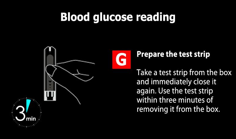
37 5.5.4 Using the Glucometer (in option) 27/06/2016 Version Page 37


38 27/06/2016 Version Page 38


39 27/06/2016 Version Page 39

40 27/06/2016 Version Page 40


41 27/06/2016 Version Page 41


42 27/06/2016 Version Page 42


43 27/06/2016 Version Page 43

44 Press the Blood sugar button to begin the USB data transmission. 27/06/2016 Version Page 44

45 Captured data are automatically displayed on the screen. You can interact with it by pressing on it. 27/06/2016 Version Page 45


46 27/06/2016 Version Page 46

47 27/06/2016 Version Page 47
 27/06/2016 Version Page")
48 5.5.5 Using the Thermometer (in option) 27/06/2016 Version Page 48


49 27/06/2016 Version Page 49


50 27/06/2016 Version Page 50

51 27/06/2016 Version Page 51

52 In Automatic wireless transmission mode Captured data are automatically displayed on the screen. You can interact with it by pressing on it. 27/06/2016 Version Page 52

53 In Manual mode Press on the Temperature button. In Manual mode You can UP or DOWN the value by pressing on the corresponding buttons. 27/06/2016 Version Page 53
54 In Manual mode Press on the Accept button to validate the value. In Manual mode Entered value is now displayed on the screen. You can interact with it by pressing on it. 27/06/2016 Version Page 54
55 5.5.6 Using the Photo module Check that the Webcam power indicator turns blue. Press the Photo / Video button on the sidebar. Select Photo, then press the Camera icon to take a picture. 27/06/2016 Version Page 55
56 The captured image is displayed on the right side of the screen. You can delete the picture by pressing on its X icon. 27/06/2016 Version Page 56
57 An alert message is displayed when you want take more than 5 photos or videos at a time. You need to delete an existing recording before adding a new one. 27/06/2016 Version Page 57

58 5.5.7 Using the Video module Check that the Webcam power indicator turns blue. Press the Photo / Video button on the sidebar. Select Video to switch into the video recording mode. 27/06/2016 Version Page 58
59 Press the Video Camera icon to record a video footage. Video recording is in progress. 27/06/2016 Version Page 59
60 Press again on the Video Camera icon to end the video footage record. You can delete the record by pressing on its X icon. 27/06/2016 Version Page 60

61 An alert message is displayed when you want take more than 5 photos or videos at a time. You need to delete an existing recording before adding a new one. 27/06/2016 Version Page 61

62 5.5.8 Using the Video Consultation module Check that the Webcam power indicator turns blue. Press the Video consultation button on the sidebar. The connection is automatic. The call is in progress. 27/06/2016 Version Page 62
63 If your correspondent is not connected, the call fail. A message is displayed. You can try calling again by pressing on the Call Again button. If the called person is connected, you need to wait until he accepts the call. 27/06/2016 Version Page 63

64 When the called person has answered the Video consultation request, his image is automatically displayed on the screen. Your own image is displayed on the corner of the screen. You can chat with the called person at any time through the chat area on the top right field of the screen. Enter your message, then press the Send button. 27/06/2016 Version Page 64
65 Your message is displayed on the screen and directly appears on the called person s own screen. To end the Video consultation, press the End call button on the sidebar. 27/06/2016 Version Page 65

66 5.5.9 Using the Telecardia ECG 27/06/2016 Version Page 66
67 27/06/2016 Version Page 67
68 27/06/2016 Version Page 68

69 27/06/2016 Version Page 69
70 27/06/2016 Version Page 70
71 The ECG trace is automatically sent to the Station. 27/06/2016 Version Page 71

72 5.6 ECG trace validation Once the capture completed, the trace is automatically sent through Bluetooth connection and displayed on the Tablet PC s touchscreen. It is possible to examine a trace in greater details by using the following functions: Examination of the ECG trace The cursor allows moving around the trace on screen: The arrows can move the trace, The round central button can move the cursor itself. The «+» and «-» buttons help enlarge or shrink the trace s image. 27/06/2016 Version Page 72

73 5.6.2 Special settings The Settings button is used to choose display formats and trace s measures. Banding : Leads are displays in banding mode, classified vertically. V Report : Vertical printing format, «portrait» mode. H Report : Horizontal printing format, «landscape» mode. 27/06/2016 Version Page 73


74 Measures : Display or non-display of ECG measures: Grid : Display or non-display of the background s grid. Calipers : Display or non-display of the calipers. Display : Configure the ECG trace display ECG measures are displayed on the medical devices screen. Press it to review the ECG trace. 27/06/2016 Version Page 74
75 5.7 Ending the Consultation Once the examination is finished and, if done previously, Patient information entered, you can validate the exams by ending the Consultation. Please first ensure proper operation of the used communication system Transmission systems The different connection levels of the selected transmission mode. Ethernet (RJ45) Plug the RJ45 extension cable to the RJ45 connecting socket at the back of the Telemedicine Station - Hardcase which is connected to the touchscreen Tablet PC. The connection is automatically done in Plug and Play mode. WiFi The touchscreen Tablet PC also has a WiFi feature (enabled by default). To establish a connection with a wireless WiFi network, simply set identifiers specific to this network connection and validate the connection. The touchscreen Tablet PC uses this connection in priority. In addition, it is possible to save the settings of the WiFi network used in order to not have to enter it for each connection. GPRS / 3G (optional) The Station could be equipped with an optional GPRS or 3G module to access the Internet wirelessly when a GPRS / 3G network is available. 27/06/2016 Version Page 75
76 5.7.2 Ending the Consultation Press the End of consultation button on the sidebar to validate the exams and end the consultation. Press the Accept button to end the consultation and automatically send the data to a secure medical cloud. 27/06/2016 Version Page 76
77 An Upload icon is displayed on the top of the screen while uploading. A message then confirms the upload success on the cloud. If no connection to a transmission system is available, the data is temporally and locally saved until the Station can connect and transmit it to the cloud. 27/06/2016 Version Page 77
 then Confirm, or by pressing the On/Off button based in the bottom right of the screen for a few seconds as presented in 5.")
78 5.8 Switching off the touchscreen Tablet PC and closing the Station software Once consultations are finished and have been sent, do not forget to switch the touchscreen Tablet PC off by: pressing Quit button (recommended) then Confirm, or by pressing the On/Off button based in the bottom right of the screen for a few seconds as presented in 5.1 until the touchscreen Tablet PC comes to a complete stop. Press the Quit button. Press the Accept button to turn off the medical station. 27/06/2016 Version Page 78


79 18. Position of the ON / STANDBY / OFF button on the touchscreen Tablet PC under the protective cover For optimal use of the Telemedicine Station - Hardcase, once the examinations have been completed and sent, you must ensure that all equipment is stored away. We therefore advise you: to make sure that each device is put away in the correct slot, to store the Telecardia Patient cable, the blood pressure flexible tube and oximeter sensor properly, making sure that they are correctly inserted in the specific slot, to check that Telecardia is correctly inserted in its vertical charger, to check that the touchscreen Tablet PC connections are correct. 27/06/2016 Version Page 79
80 6 Software upgrade / initialisation The Telemedicine Station - Hardcase comes with a configured and operational touchscreen Tablet PC. Any software updates are carried out during maintenance operations. PARSYS Telemedicine will contact you and tell you how to perform the update procedure. We therefore advise you: NEVER ATTEMPT to configure it yourself, to contact the PARSYS Telemedicine After-Sales Service or appointed distributor. 27/06/2016 Version Page 80
81 7 Products technical features 7.1 General features of the Station Type: Hardcase - Pelicase 1450 Dimensions: 420 x 331 x 174 mm Weight: 7 Kg Materials: ABS / Polypropylene / Polymer Protection: IP66 Connectivity: 1 2P male sector 1 RJ45 Ethernet socket Operation: On rechargeable batteries Power supply: Input: V ~ / Hz /1.1A Output: 12V DC 3.8A max current consumption Medical supply model: FRIWO Desktop Power Supply Ref: FW7405M/12 Class II certified EN Battery life: Typically 8.00 hours Using temperature: 10 ~ 35 C Recharging temperature: 10 ~ 35 C Transportation and Storage temperature: -10 ~ 50 C Using relative humidity: 30% to 85% Recharging relative humidity: 30% to 85% Transportation and Storage relative humidity: 30% to 85% 27/06/2016 Version Page 81
82 7.2 Touchscreen Tablet PC Model: ASUS Transformer Book - T100TA-DK002H - Intel Atom Z3740 OS: Windows bits WLAN Standard: a/b/g/n Mini HDMI: 1 USB 3.0 ports: 1 Network: Yes Bluetooth : Yes Wireless mode: Bluetooth 4.0 class 1 Graphics: Integrated Intel HD Graphics Display type: LED Touchscreen Screen size: 10.1 inches Resolution: 1366 x 768 pixels Processor speed: 1.33 GHz / 1.86 GHz Turbo Internal memory: 2GB Processor model: Intel Atom Z3740 Capacity: 32.0 GB Manufacturer: ASUS Power: 5V 10W AC/DC Adapter Battery: Lithium Polymer Battery Battery life: 11.0 hours Dimensions: 263 x 171 x 10.5 mm Weight: Kg. 27/06/2016 Version Page 82
83 7.3 Telecardia ECG General features Portable, event-driven, 12-lead temporary electrocardiograph. Radio data transmission (Bluetooth). Lithium polymer rechargeable battery power supply Mechanical features Material: two half-body unit + one hinged hatch made of flame-retardant ABS Color: RAL 9002 white with marking Surface condition: 26 arbours Electrode on unit: o chest on lower section VN - V1 - V2 - V3 - V4 - V5 - V6 (7/10µ chromium-plated brass) Electrodes with cable: o VR, VL and VF peripheral limb clips cable Connectors: o "female cylinder connectors with collar" under bushing cover for electrocardiograph connection - analogue trace output Protection index: IP20 Folded overall dimensions: 210 mm x 100 mm x 50 mm Weight: < 550 g Electrical specifications Device intended for temporary use. Device not protected against defibrillation shocks. Device with internal electricity supply: rechargeable lithium polymer batteries Battery life: 50 peri-critical ECG captures and Bluetooth transmission in one battery charge Automatic power off after transmission. Internal protection using 500mA resettable fuse. Type B class 2A machine, diagnostic function. Measurement with internal electrodes, 9 simultaneous leads: VR, VL, VF, V1 - V2 - V3 - V4 - V5 - V6 with reference to VN. Reproduction of 12 leads: D1, D2, D3, VR, VL, VF, V1, V2, V3, V4, V5, V6 Input impedance: 10 MΩ. Bandwidth: 0.16Hz to 70Hz at -3db (Adjustable to 30Hz by configuration) Measurement linearity: 0,01% Measurement sensitivity: 2264 pt/mv Sampling frequency: 271 pt/s Backup of 6 (peri-critical) 15-second ECGs (rotating or fixed list backup management with saving maintained even without stack). Saving of identification and configuration data in encrypted form. Real-time clock for ECG dating (autonomy of 1 year from full charging level under normal storage conditions). Displayed and/or voice task procedure or action messages. 2-line, 16-character screen: task procedure message display Operating mode setting (computer configuration): o maximum number of ECGs o voice prompt o rotating stack/locking 27/06/2016 Version Page 83
84 o connection type Bluetooth type interface for computer link and transmission base link: o Bluetooth version 2.0 (EDR) o Class 1 (100 mw) Average transmission speed: Kb/s (depends on medium used) Operating conditions: o Temperature: +10 C to +35 C o Relative humidity level: 30% to 75% o Atmospheric pressure: 700 mb to 1060 mb. Storage and transport conditions: o Temperature: -10 C to +50 C o Relative humidity level: 10% to 85% o Atmospheric pressure: 500 mb to 1060 mb Functional features Front panel: start-up button, configuration button (under bushing cover), blue/green LED indicating: o steady green - machine power on o steady blue - Bluetooth transmission to PC or base 1 LCD 2 x 16-character line screen without backlighting. Curved lower section: 3 chromium-plated brass convex round electrodes Upper section: Hatch opening outwards and used to support the unit Upper section under hatch: 10 x 4 mm "female cylindrical" connectors with attachment collar between the two bodies 1 signal transfer control button to electrocardiograph (analogue output), or configuration Rear panel (back): Instruction label 2 charging contacts Edges: 1 folding articulated arm on either side, supporting electrodes V1, V2 and V5, V6. Under the right arm, 1 connecting socket for VR, VL and VF limb clips cable. 27/06/2016 Version Page 84
85 7.4 Biosys General features Biosys is a device designed for use in emergency mode and outdoors: Class: IIa Dimensions: 162 mm x 176 mm x 38 mm Weight: 500 g Power: 5V Battery: Built-in Lithium Polymer Battery Protection index: IP20 Operating temperature: 10 ~ 40 C Charging temperature: 10 ~ 40 C Temperature storage and transport: -10 ~ 50 C Atmospheric pressure: 700 mb to 1060 mb Atmospheric pressure refueling: 700 mb to 1060 mb Atmospheric transport and storage: from 500 mb to 1060 mb Relative humidity range: 30 % to 75% Relative humidity charging: 30 % to 75 % Relative humidity transport and storage : 10 % to 85 % Standards applied: EN , 9919, , Oximetry (SPO2) Measuring range: 0 ~ 100% Resolution: ± 1% Accuracy: ± % 3 79 ± 70% Pulse Rate Measurement Range: bpm Resolution: 1 bpm Accuracy: ± 2% or 2bpm Blood pressure (NIBP) Measurement method: Oscillometric. Measuring mode: o Manual - Automatic (1 to 240mn interval between each measurement) o Automatic (adjustable cycles) Measurement unit: mmhg Measurement range: Adult Systolic / Diastolic 15 to 255mmHg Measurement resolution: 1 mmhg Measurement accuracy: ± 5 mmhg on average, maximum ± 8mmHg 27/06/2016 Version Page 85
86 7.5 USB Webcam Brand: Logitech Model: Name: Logitech HD Pro C920 - Carl Zeiss Weight: Kg Connection: Wired Interface: USB 2.0 Color: Black Resolution : Full HD 1080p Microphone: Built-in 7.6 Glucometer (in option) See the Glucometer s User Manual provided in option with the Station. 7.7 Thermometer (in option) See the Thermometer s User Manual provided in option with the Station. 27/06/2016 Version Page 86
87 8 Electromagnetic emissions 8.1 Telecardia Table 1: Directives and MANUFACTURER S statement ELECTROMAGNETIC EMISSIONS For all DEVICES and EM SYSTEMS Directives and manufacturer s statement electromagnetic emissions The device is made to be used in the electromagnetic environment specified below. The client or user of the device must ensure that the device is used in such environment. Emission trials Conformity Electromagnetic environment directives RF Emissions CISPR 11 RF Emissions CISPR 11 Harmonic Emissions CEI Pulse fluctuations/ Flicker CEI Group 1 Class B Non applicable Non applicable The device uses RF energy only through his internal functions. As a consequence, its RF emissions are very weak and are not likely to cause interferences in a nearby electronic device. The charging power box (catalogue product) must solely be used with the device in sleep mode, disconnected from the patient. Table 2 Directives and MANUFACTURER S statement electromagnetic IMMUNITY For all DEVICES and EM SYSTEMS Directives and manufacturer s statement electromagnetic immunity The device is made to be used in the electromagnetic environment specified below. The client or user of the device must ensure that the device is used in such environment. 27/06/2016 Version Page 87
88 Immunity trials Trial level CEI Conformity level Electromagnetic environment directives Electrostatic shocks (ES) CEI Magnetic field at the rate of the electric network (50/60 Hz) CEI /- 6 kv in contact +/- 8 kv in the air Conforms Floors must be made of wood, concrete or ceramics. If the floors are topped with synthetic materials, it is important that the relative humidity remains at 30% at least. 3 A/m Conforms Magnetic fields at the rate of the electric network must have the distinctive levels of a representative place located in a commercial or hospital environment. 27/06/2016 Version Page 88
89 Table 3 Directives and MANUFACTURER S statement - electromagnetic IMMUNITY For all DEVICES and EM SYSTEMS Directives and manufacturer s statement electromagnetic emissions The device is made to be used in the electromagnetic environment specified below. The client or user of the device must ensure that the device is used in such environment. Emission trials Trial level CEI Conformity level Electromagnetic environment directives The portable and mobile RF communicating devices should be not used nearer of any part of the medical devices, including cables, than the recommended separation distance, calculated from the transmitter frequency applicable equation. Recommended separation distance d= 1,2 P RF conducted disturbances CEI Veff from 150kHz to 80MHz 3 Veff d= 1,2 P from 80MHz to 800MHz d= 2,3 P from 800MHz to 2,5GHz RF radiated disturbances CEI V/m from 80 to 2,5GHz 3 V/m where P is the maximum output power of the transmitter in watts (W) according to the transmitter manufacturer and d is the recommended separation distance in meters (m) of separation. It should that field strengths from fixed RF transmitters, as determined by an electromagnetic survey on site a, should be less than the compliance level in each frequency range b.. Interferences may occur in the vicinity of equipment marked with the following symbol: NOTE 1: to 80MHz and to 800MHz, the higher d range frequency applies. NOTE 2: These guidelines may not apply in all situations. Electromagnetic propagation is affected by absorption and reflection from structures, objects and people. a Field strengths from fixed transmitters, such as base stations for radio (cellular / cordless) telephones and land mobile radios, amateur radio, AM / FM radio and TV broadcast cannot be predicted theoretically with accuracy. To assess the electromagnetic environment due to fixed RF transmitters, it should be considered to proceed to an electromagnetic survey on site. If the measured field strength in the location where the medical device is used, exceeds the applicable RF compliance level above, it is necessary to observe the behavior of the medical device, to check that the operation is normal. If abnormal performances are observed, additional measures may be necessary, such as reorienting or repositioning of the medical device on its operation site. b In the frequency range of 150kHz to 80MHz, it is appropriate that the field strengths are smaller than 3 V/m. 27/06/2016 Version Page 89
90 Recommended separation distances between portable and mobile RF communicating devices and the medical device. The medical device is intended for use in an electromagnetic environment where radiated RF disturbances are controlled. The customer or the user of the device can help to prevent electromagnetic interference by maintaining a minimum distance between portable and mobile RF communicating device (transmitter), and the medical device, as recommended below, according to the maximum power emission of the communication device. Transmitter maximum assigned power output (W) Separation distance according to the transmitter frequency (m) from 150kHz to 80MHz d= 1,2 P from 150kHz to 80MHz d= 1,2 P from 150kHz to 80MHz d= 2,3 P 0,01 0,12 0,12 0,23 0,1 0,38 0,38 0,73 1 1,2 1,2 2,3 10 3,8 3,8 7, For transmitters whose maximum assigned transmission power is not given above, the recommended separation distance d in meters (m) can be estimated by using the transmitter frequency applicable equation, where P is the characteristic of the transmitter maximum transmission power in watts (W) according to its manufacturer. NOTE 1: to 80MHz and to 800MHz, the higher d range frequency applies. NOTE 2: These guidelines may not apply in all situations. Electromagnetic propagation is affected by absorption and reflection from structures, objects and people. 27/06/2016 Version Page 90
91 8.2 Biosys Table 1: Directives and MANUFACTURER S statement ELECTROMAGNETIC EMISSIONS For all DEVICES and EM SYSTEMS Directives and manufacturer s statement electromagnetic emissions The device is made to be used in the electromagnetic environment specified below. The client or user of the device must ensure that the device is used in such environment. Emission trials Conformity Electromagnetic environment directives RF Emissions CISPR 11 RF Emissions CISPR 11 Harmonic Emissions CEI Pulse fluctuations/ Flicker CEI Group 1 Class B Non applicable Non applicable The device uses RF energy only through his internal functions. As a consequence, its RF emissions are very weak and are not likely to cause interferences in a nearby electronic device. The charging power box (catalogue product) must solely be used with the device in sleep mode, disconnected from the patient. Table 2: Directives and MANUFACTURER S statement electromagnetic IMMUNITY For all DEVICES and EM SYSTEMS Directives and manufacturer s statement electromagnetic immunity The device is made to be used in the electromagnetic environment specified below. The client or user of the device must ensure that the device is used in such environment. Immunity trials Trial level CEI Conformity level Electromagnetic environment directives Electrostatic shocks (ES) CEI Magnetic field at the rate of the electric network (50/60 Hz) CEI /- 6 kv in contact +/- 8 kv in the air Conforms Floors must be made of wood, concrete or ceramics. If the floors are topped with synthetic materials, it is important that the relative humidity remains at 30% at least. 3 A/m Conforms Magnetic fields at the rate of the electric network must have the distinctive levels of a representative place located in a commercial or hospital environment. 27/06/2016 Version Page 91
92 Table 3 Directives and MANUFACTURER S statement electromagnetic IMMUNITY For all DEVICES and EM SYSTEMS Directives and manufacturer s statement electromagnetic emissions The device is made to be used in the electromagnetic environment specified below. The client or user of the device must ensure that the device is used in such environment. Emission trials Trial level CEI Conformity level Electromagnetic environment directives The portable and mobile RF communicating devices should be not used nearer of any part of the medical devices, including cables, than the recommended separation distance, calculated from the transmitter frequency applicable equation. Recommended separation distance d= 1,2 P RF conducted disturbances CEI Veff from 150kHz to 80MHz 3 Veff d= 1,2 P from 80MHz to 800MHz d= 2,3 P from 800MHz to 2,5GHz RF radiated disturbances CEI V/m from 80 to 2,5GHz 3 V/m where P is the maximum output power of the transmitter in watts (W) according to the transmitter manufacturer and d is the recommended separation distance in meters (m) of separation. It should that field strengths from fixed RF transmitters, as determined by an electromagnetic survey on site a, should be less than the compliance level in each frequency range b.. Interferences may occur in the vicinity of equipment marked with the following symbol: NOTE 1: to 80MHz and to 800MHz, the higher d range frequency applies. NOTE 2: These guidelines may not apply in all situations. Electromagnetic propagation is affected by absorption and reflection from structures, objects and people. a b Field strengths from fixed transmitters, such as base stations for radio (cellular / cordless) telephones and land mobile radios, amateur radio, AM / FM radio and TV broadcast cannot be predicted theoretically with accuracy. To assess the electromagnetic environment due to fixed RF transmitters, it should be considered to proceed to an electromagnetic survey on site. If the measured field strength in the location where the medical device is used, exceeds the applicable RF compliance level above, it is necessary to observe the behavior of the medical device, to check that the operation is normal. If abnormal performances are observed, additional measures may be necessary, such as reorienting or repositioning of the medical device on its operation site. In the frequency range of 150kHz to 80MHz, it is appropriate that the field strengths are smaller than 3 V/m. 27/06/2016 Version Page 92
93 Recommended separation distances between portable and mobile RF communicating devices and the medical device. The medical device is intended for use in an electromagnetic environment where radiated RF disturbances are controlled. The customer or the user of the device can help to prevent electromagnetic interference by maintaining a minimum distance between portable and mobile RF communicating device (transmitter), and the medical device, as recommended below, according to the maximum power emission of the communication device. Transmitter maximum assigned power output (W) Separation distance according to the transmitter frequency (m) from 150kHz to 80MHz d= 1,2 P from 150kHz to 80MHz d= 1,2 P from 150kHz to 80MHz d= 2,3 P 0,01 0,12 0,12 0,23 0,1 0,38 0,38 0,73 1 1,2 1,2 2,3 10 3,8 3,8 7, For transmitters whose maximum assigned transmission power is not given above, the recommended separation distance d in meters (m) can be estimated by using the transmitter frequency applicable equation, where P is the characteristic of the transmitter maximum transmission power in watts (W) according to its manufacturer. NOTE 1: to 80MHz and to 800MHz, the higher d range frequency applies. NOTE 2: These guidelines may not apply in all situations. Electromagnetic propagation is affected by absorption and reflection from structures, objects and people. 27/06/2016 Version Page 93
94 9 Users Training It is imperative that the use of Telemedicine Station - Hardcase be performed under the supervision of a medical doctor. In all cases, the user must have received prior training in the use of Station s equipment. 27/06/2016 Version Page 94
95 10 Maintenance 10.1 Telecardia ECG maintenance Cleaning / Disinfection The Telecardia machine can be cleaned and disinfected by wiping the electrodes in contact with the skin and the plastic unit, except on the self-adhesive label at the rear of the machine, with cotton wool or a wipe soaked in a product such as STERANIOS or equivalent (2% glutaraldehyde solution). Any other product would not ensure proper cleaning without damaging the Telecardia components Procedure in the event that the device is dropped or falls Mechanical damage to the device necessarily implies discontinuation of use of the machine and return to the PARSYS Telemedicine After-Sales Service Reset procedure If, when using the device, it blocks for more than 1 min: Use the reset cable or take a metal object (paper clip) and place it on the charging contacts for 1s, Place the equipment back on the charger and wait for the Charger indicator to come on, Establish radio connection with the PC in configuration mode in order to update the device's internal real-time clock: Open the cover as shown on the photo: press and hold the "OUT" button and press the GREEN ON/OFF button at the same time. When the machine displays "PARSYS Santé", release both buttons. The machine then indicates the time and date, before displaying "en cours" (in progress) and "connexion BT" (BT connection). Restart the device. 27/06/2016 Version Page 95
96 Metrological checks The device shall undergo metrological checks after 1 year maximum. Checks should be carried out by the PARSYS Telemedicine technical department, it alone being able to guarantee maintenance of the device's metrological performance Discharged battery We recommend not to let Telecardia discharged for more than 1 year to keep the device's internal real-time clock Product scrap treatment According to the directive 2002/96/CE relating to DEEE electronic and electric devices, do not throw away in regular trash. Please bring waste to specialized collection points. 27/06/2016 Version Page 96
97 10.2 Biosys maintenance Cleaning / Disinfection The device s plastic box can be cleaned and disinfected with a cotton wool or a wipe soaked in a product such as STERANIOS or equivalent (2% glutaraldehyde solution). If items have been in contact with blood, the recommended disinfectant is INCIDIN FOAM Procedure in the event that the device is dropped or falls Mechanical damage to the device necessarily implies discontinuation of use of the device and return to the PARSYS Telemedicine After-Sales Service or distributor Reset procedure If the device is blocked or if the software interaction is dysfunctional, simply unplug the USB and power cords located in the back of the device, and wait until its battery is empty in order to reset it Metrological checks The device shall undergo metrological checks after 1 year maximum. Checks should be carried outby the PARSYS Telemedicine technical department, it alone being able to guarantee maintenance of the device's metrological performance Product scrap treatment According to the 2002/96/CE directive relating to DEEE electronic and electric devices, do not throw away in regular trash. Please bring waste to specialized collection points. 27/06/2016 Version Page 97
98 Checking the pressure static accuracy of the blood pressure arm cuff / Air leakage measurement of the blood pressure arm cuff. To check the static accuracy and the arm cuff air leakage pressure, you should first made a test bench by following one of two possible schemes: Arm cuff 1 Manometer Medical Device NIBP Input Inflating device 2 Arm cuff Medical Device Manometer NIBP Input When the test bench is made, please follow the following procedure: 1. From the main screen, press the Settings button. 2. Press the Calibration button. 3. A dialog allows the operator to select the initial arm cuff pressure, depending on the operation mode, either Adult, Neonatal or even manual. This value can be adjusted within the following ranges: Adult: mmhg Neonat: mmhg Manual: mmhg 27/06/2016 Version Page 98


99 19. Arm cuff initial pressure settings window 4. During the test, a dialog displays in continuous the arm cuff pressure measure. 20. Arm cuff pressure measure test dialog 27/06/2016 Version Page 99
100 10.3 Touchscreen Tablet PC maintenance Caution: fragile Touchscreen! Screen cleaning rules: 1. Do not use a tissue or a paper towel to clean the touchscreen; their use may cause scratches on the screen. 2. Do not use any glass cleaner or any other cleaners. Indeed, repeated use of any cleaning agents could lead to irreversible damage to the Tablet PC, thus hindering its smooth operation Cleaning the screen A deposit of dust or too many fingerprints on the screen can limit the use of the touchscreen Tablet PC. To clean the screen: 1. Use an anti-static cloth. 2. Turn off the Tablet PC: It helps protect the Tablet and better identify dust and fingerprints on it. 3. Moisten the anti-static cloth with water or spray it with a special screen cleaner - disinfectant or not according to your needs. Do not directly dampen or spray on the screen. 4. Carefully clean the screen with the cloth and let it dry. 27/06/2016 Version Page 100
101 11 Malfunctions 11.1 Telecardia ECG The Telecardia ECG does not send any trace After capturing the ECG, no trace is received by the touchscreen Tablet PC: the Bluetooth connection is most certainly lost. We therefore advise you: NEVER ATTEMPT any direct manipulation on the touchscreen Tablet PC; Contact the PARSYS Telemedicine After-Sales Service The ECG is subject to interference Check that the capture protocol described in section has been followed, in particular: that the correct color code has been followed for the limb clips: red on the right arm, yellow on the left arm and green on the left leg, that the electrodes and the skin have been humidified: using the spray. The patient and operator must be as relaxed as possible in order to avoid any tense movements when capturing the ECG The Telecardia ECG is not charging Check that the protocol described in section has been followed, in particular: that the Telecardia is in the correct position on the charger, that the red LED on the charger is on during charging, that the Telemedicine Station - Hardcase is correctly plugged into the mains. Should you note a low battery level after 1 hour's charging, please contact the PARSYS Telemedicine After- Sales Service. 27/06/2016 Version Page 101
102 The Telecardia ECG remains blocked If, when using the device, it blocks for more than 1 min: Use the reset cable or take a metal object (paper clip) and place it on the charging contacts for 1s, Place the equipment back on the charger and wait for the Charger indicator to come on, Establish radio connection with the PC in configuration mode in order to update the device's internal real-time clock: Open the cover as shown on the photo: press and hold the "OUT" button and press the GREEN ON/OFF button at the same time. When the machine displays "PARSYS Santé", release both buttons. The machine then indicates the time and date, before displaying "en cours" (in progress) and "connexion BT" (BT connection). Restart the device The Telecardia ECG has lost is time stamping If your Telecardia ECG has lost is time stamping: Establish radio connection with the PC in configuration mode in order to update the device's internal real-time clock: Open the cover as shown on the photo: press and hold the "OUT" button and press the GREEN ON/OFF button at the same time. When the machine displays "PARSYS Santé", release both buttons. The machine then indicates the time and date, before displaying "en cours" (in progress) and "connexion BT" (BT connection). Restart the device. 27/06/2016 Version Page 102
103 11.2 Biosys Software troubleshooting (screen lock, Windows display) Biosys comes with configured and operational software. Software updates are performed during maintenance operations. For each update, PARSYS Telemedicine contacts you and tells you how to update. We recommend that you: NEVER ATTEMPT an update by yourself, Contact the customer service of PARSYS Telemedicine or its distributor The device is no longer recognized after launching the software If after checking the correct connection of the Biosys to the touchscreen Tablet PC and launching the appropriate software, the device still does not respond, please contact the customer service of PARSYS Telemedicine and do not try to modify it by yourself. We recommend that you: NEVER ATTEMPT an update by yourself, Contact the customer service of PARSYS Telemedicine or its distributor The unit does not respond to commands from the software Check the correct connection of the Biosys to the touchscreen Tablet PC. If the device does not respond, please complete the reset procedure presented in , then quit and restart the application on the touchscreen Tablet PC. If Biosys still does not respond, please contact the customer service of PARSYS Telemedicine or its distributor and do not try to change it yourself. We recommend that you: NEVER ATTEMPT a modification by yourself, Contact the customer service of PARSYS Telemedicine or its distributor Connection and charging LED indicators don t turn on Check the correct connection of Biosys to the touchscreen Tablet PC. If no LED is lit, please complete the reset procedure presented in If again no lights show up, please contact the customer service of PARSYS Telemedicine or its distributor and do not try to change it yourself. We recommend that you: NEVER ATTEMPT a modification by yourself, Contact the customer service of PARSYS Telemedicine or its distributor. 27/06/2016 Version Page 103
104 Malfunctions related to wired sensors We invite you to check that: the sensors are connected correctly, the measurement protocol is followed, sensors show no signs of deterioration (cable cut or flattened, broken sensor,...). 27/06/2016 Version Page 104
, and at the request of the technician, please follow this procedure: Press the \"Support\"")
105 11.3 Remote control Though, if a problem persists, contact the After-Sales Service of PARSYS Telemedicine (see section 12). The technician may ask you to give him the remote control of your equipment. First make sure that your equipment is connected to a communication system (Ethernet, WiFi or GPRS / 3G), and at the request of the technician, please follow this procedure: Press the "Support" button. A "Teamviewer" window automatically appears. The technician needs you to give him the displayed ID number of your equipment to open the access. 27/06/2016 Version Page 105
Télécardia Electrocardiograph
 Telemedicine Anytime, Anywhere U S E R M A N U A L Télécardia Electrocardiograph 37-021 V4.1 Date of the first placing on the market of the product: January 2007 12/06/2016 Version TABLE OF CONTENTS 1
Telemedicine Station HARDCASE
 Telemedicine Anytime, Anywhere U S E R M A N U A L Telemedicine Station HARDCASE 37-034 V1.7 Date of product s first placing on the market: January 2016 01/12/2016 Version www.parsys.com 01/12/2016 Version
Site~Rite Prevue Ultrasound System and Site~Rite Prevue+ Ultrasound System Technical Manual
 Site~Rite Prevue Ultrasound System and Site~Rite Prevue+ Ultrasound System Technical Manual 9770088 System Technical Manual 3 Table of Contents Section 1 Statement of Purpose 2 2.1 2.2 2.3 System Overview
#
 INSTALLATION MANUAL Contents Getting To Know Your AVANT HIT+ TM... 3 Setting up the System... 4 Software Installation... 5 Driver Installation Windows 7... 8 Driver Installation Windows XP... 11 Accessories...
Technical Specifications Micromedical VisualEyes 515 VisualEyes 525 by Interacoustics
 VisualEyes 515 and VisualEyes 525 - Technical Specifications Page 0 Technical Specifications Micromedical VisualEyes 515 VisualEyes 525 by Interacoustics D-0109757-B 2017/05 VisualEyes 515 and VisualEyes
User Guide. Version 2.
 User Guide Version 2 www.rmepad.com RM epad TM User Guide Please read all instructions carefully before using Please retain these instructions for future reference RM epad TM contains replaceable, rechargeable
Cardiostart. Biphasic Defibrillator Monitor
 Cardiostart Biphasic Defibrillator Monitor Standard Accessories Carrying Case Rechargeable lithium ion battery Set of accessories Other accessories upon request Internal Pads Adult / Pediatric / Neonatal
Argentine Manufacturer of Hospital Equipment. Electrocardiograph Pulse Oximeters Vital Signs Monitors
 Electrocardiograph Pulse Oximeters Vital Signs Monitors ELECTROCARDIOGRAPH Model: RG-401plus Model: RG-401 ELECTROCARDIOGRAPH Model: RG-401 Technical Specifications Accessories Carrying bag Patient cable
USB 3.0 Docking Station
 USB 3.0 Docking Station Dual Display DVI+HDMI - 6 PORT USB HUB - LAN - AUDIO User Manual HDOCKS300 www.hamletcom.com Index 1. INTRODUCTION... 5 2. PRODUCT OVERVIEW... 6 2.1 PORTS AND CONNECTORS... 6 3.
f200 English User Manual Contents
 f200 English User Manual Contents About this Guide...3 FCC Statement...3 WEEE Notice...3 CE Regulatory Notice...4 Notes on Installation...4 Caution...4 1 Introduction...5 1.1 Features...5 1.2 Package Contents...5
IMPORTANT SAFETY INSTRUCTIONS SAVE THESE INSTRUCTIONS
 IMPORTANT SAFETY INSTRUCTIONS IMPORTANT SAFETY INSTRUCTIONS SAVE THESE INSTRUCTIONS WARNING (SAVE THESE INSTRUCTIONS): This manual contains important instructions that should be followed during installation
CDRPan. User Guide FOR PANORAMIC SYSTEMS. Schick Technologies, Inc th Avenue Long Island City, New York 11101
 CDRPan FOR PANORAMIC SYSTEMS User Guide Schick Technologies, Inc. 31-00 47 th Avenue Long Island City, New York 11101 (718) 937-5765 (718) 937-5962 (FAX) Part Number B1051008 Rev. B Copyright 2004 by Schick
#0086.
 Contents Getting to Know Your AVANT REM series... 3 Computer Requirements...... 4 Avant REM+.. 5 Avant REMsp.. 6 Transducer and Accessories 7 Connecting the Speaker 8 Software Installation... 9 EMC Precautions
FengMi Wemax One Laser Projection TV
 FengMi Wemax One Laser Projection TV User`s Manual About electrical ground Transportation Use this device only with a compulsory grounding condition. It is recommended that you use the original packaging
QK5P1000-Manual_Cover-135x135mm_PrintReady.eps 1 2/7/ :52:09 AM CMY 291-MB384-01S4F
 QK5P1000-Manual_Cover-135x135mm_PrintReady.eps 1 2/7/2018 11:52:09 AM C M Y CM MY CY CMY K 291-MB384-01S4F User s Manual No part of this manual, including the products and software described in it, may
Control Panel CP600 CP635, CP635-B, CP635-WEB
 DATA SHEET Control Panel CP600 CP635, CP635-B, CP635-WEB 1 Ordering Data Part No. Description Product Life Cycle Phase 1SAP535100R0001 CP635, control panel, TFT graphical display, single-touch screen,
Control Panel CP600 CP651, CP651-WEB
 DATA SHEET Control Panel CP600 CP651, CP651-WEB 1 Ordering Data Part No. Description Product Life Cycle Phase 1SAP551100R0001 CP651, control panel, TFT graphical display, single-touch screen, 10.4, Active
1. Introduction P Package Contents 1.
 1 Contents 1. Introduction ------------------------------------------------------------------------------- P. 3-5 1.1 Package Contents 1.2 Tablet Overview 2. Using the Tablet for the first time ---------------------------------------------------
All your entertainment in one place
 Quick Start Guide What s inside Step 1. Unpack the box Important Tips Step 2. Connect to your Broadband Modem Step 3. Connect to your TV Antenna Step 4. Connect to your TV Step 5. Power up your Fetch Mighty
User Manual SP2-4K. 4K HDMI Splitter 1x2. All Rights Reserved. Version: SP2-4K_2016V1.0
 User Manual SP2-4K 4K HDMI Splitter 1x2 All Rights Reserved Version: SP2-4K_2016V1.0 SAFETY PRECAUTIONS To insure the best from the product, please read all instructions carefully before using the device.
ZOTAC ZBOX nano. User s Manual
 User s Manual ZOTAC ZBOX nano No part of this manual, including the products and software described in it, may be reproduced, transmitted, transcribed, stored in a retrieval system, or translated into
Control Panel CP600-eCo CP604, CP604-B
 DATA SHEET Control Panel CP600-eCo CP604, CP604-B 1 Ordering Data Part No. Description Product Life Cycle Phase 1SAP504100R0001 CP604, control panel, TFT graphical display, single-touch screen, 4.3, Active
Wireless TV Chin Guard Headphone TX-99
 Technaxx * User Manual Wireless TV Chin Guard Headphone TX-99 With this comfortable and good-fitting headphone you can enjoy listening to television or music at your preferred volume without disturbing
Control Panel CP600 CP635-FB, CP635-FW
 DATA SHEET Control Panel CP600 CP635-FB, CP635-FW 1 Ordering Data Part No. Description Product Life Cycle Phase 1SAP535110R6001 CP635-FB, control panel, TFT graphical display, single-touch projected Active
User Manual. GSM Fixed Wireless Phone (Model: GSM-938) Introduction
 Introduction") User Manual Introduction The latest style desktop wireless telecommunication products. It can send wireless SMS and voice at anytime, anywhere, suitable remote countries or mountains. Please take care
User Manual Introduction The latest style desktop wireless telecommunication products. It can send wireless SMS and voice at anytime, anywhere, suitable remote countries or mountains. Please take care
DreamStation Cellular Modem
 DreamStation Cellular Modem INSTALLATION AND OPERATION GUIDE Intended Use The DreamStation Cellular Modem is designed for use with select Philips Respironics therapy devices. Once installed, it can transfer
ZOTAC ZBOX. User s Manual
 User s Manual ZOTAC ZBOX No part of this manual, including the products and software described in it, may be reproduced, transmitted, transcribed, stored in a retrieval system, or translated into any language
User Manual. Cobia Flex R/F English - v2016.5a
 User Manual Cobia Flex R/F English - v2016.5a NOTICE RTI Electronics AB reserves the right to make changes to the Cobia Flex R/F and the information in this user manual without prior notice. RTI Electronics
Specification System... 5 Display Specification... 5 I/O Connectors... 5 Buttons and Indicators... 5
 ALGIZ 10X INDEX... 4 1. IDENTIFYING ALGIZ 10X... 5 Specification... 5 System... 5 Display Specification... 5 I/O Connectors... 5 Buttons and Indicators... 5 COM Port Assignment... 6 Boot Options... 6 Factory
DEUTSCH ENGLISH NEDERLANDS FRANÇAIS NORSK ITALANIO ČEŠTINA Hersteller DAB650SI
 DEUTSCH NEDERLANDS NORSK ČEŠTINA ENGLISH FRANÇAIS ITALANIO Hersteller Wörlein GmbH Tel.: +49 9103/71670 Gewerbestrasse 12 Fax.: +49 9103/716712 D 90556 Cadolzburg Email. info@woerlein.com GERMANY Web:
Quick start Guide POCKET TV
 Quick start Guide POCKET TV SAFETY WARNING Exposure -Do not place the Pocket TV or remotes on an unstable surface. -Keep all electronics away from direct exposure to the sun and other sources of heat.
Lenovo Flex User Guide. Read the safety notices and important tips in the included manuals before using your computer.
 Lenovo Flex 3-1130 User Guide Read the safety notices and important tips in the included manuals before using your computer. Notes Before using the product, be sure to read Lenovo Safety and General Information
SL2400 Compact Monitor
 Summary The Ultraview SL 2400 is a compact monitoring system with a 10.4-inch resistive touchscreen display. Dual-battery slots allow this monitor to be used in transport, as well as at the bedside. The
SleepMinder TM Non Contact Sleep Monitoring
 SleepMinder TM Non Contact Sleep Monitoring ABOUT THE SLEEPMINDER TM The SleepMinder TM uses a specially-designed motion sensor to detect body movement associated with sleeping. It can be used in the home,
Quick Start Guide. For Android Tablet TR10RS1
 Quick Start Guide For Android Tablet TR10RS1 Federal Communication Commission Interference Statement This equipment has been tested and found to comply with the limits for a Class B digital device, pursuant
#0086.
 INSTALLATION MANUAL Contents Getting to Know Your AVANT A2D+... 3 Software Installation... 5 Driver Installation Windows 7... 8 Loading Calibration Files... 11 EMC Precautions... 12 Safety... 15 Limited
ZOTAC ZBOX. User s Manual
 User s Manual ZOTAC ZBOX No part of this manual, including the products and software described in it, may be reproduced, transmitted, transcribed, stored in a retrieval system, or translated into any language
Cat videocam. User s guide
 Cat videocam User s guide User s guide Before using your pet cam, please read the instructions in this guide carefully and keep it for future reference. Technical specifications Product Size Physical weight
1. Table Parts. Public
 Contents 1. Tablet Parts 2. Key Layouts and Definitions 3. Getting Started 4. The Start Screen 5. Applications 6. Charm Menu 7. Using Two Application at Once 8. Factory Reset 9. Safety Information 10.
OPERATING INSTRUCTIONS 7 SERIES STATIC GENERATORS
 OPERATING INSTRUCTIONS 7 SERIES STATIC GENERATORS GB Contents Page 1 Introduction 4 2 Safety 5 3 Use 6 4 Checking on Delivered Equipment 6 5 General Specification and Dimensions 7 6 Positioning 10 7 Operating
TABLET PC. Quick Start Guide. Model: TVE100 I
 TABLET PC Quick Start Guide Model: TVE100 I Safety Precautions 1. This production is suitable for use in non-tropic areas below 2,000 meters, and the mark in the nameplate indicates the product is suitable
User Manual. Stoltzen SHSP14 HDMI Splitter 1x4. 4K HDMI Splitter 1x4. All Rights Reserved. Version: SHSP14_2016V2
 User Manual 4K HDMI Splitter 1x4 All Rights Reserved Version: SHSP14_2016V2 SAFETY PRECAUTIONS To insure the best from the product, please read all instructions carefully before using the device. Save
FMT1000BT DAB+ Transmitter
 Technaxx * User Manual FMT1000BT DAB+ Transmitter The manufacturer Technaxx Deutschland GmbH & Co.KG hereby declares that this device, to which this user manual belongs, complies with the essential requirements
Resting and Stress ECG
 Operating Manual Resting and Stress ECG 1 Safety Hardware 3 Software 4 Hygiene Part : Operating characteristics: 1-channel PC ECG, Resting & stress ECG MHW 0013 - DK 1716 Version 001-3/0/018 018 custo
ECG100S. General Information. Product Code
 General Information Product Name General Name Product Code 80508096 Manufacturer Device Description Intended Use Cardioline Spa Registered Office and Factory: Via Linz, 19-20-21 Zona Ind. Spini di Gardolo
91370 SL2600 Compact Monitor
 Summary The Ultraview SL 2600 is a versatile compact monitoring system with a 12.1-inch resistive touchscreen display. Dual-battery slots allow this monitor to be used in transport, as well as at the bedside.
MC 11 EB-2 Power supply cabinet with external bus, AC version
 MC 11 EB-2 Power supply cabinet with external bus, AC version USER/MAINTENANCE MANUAL 1 SLOT 0 SLOT 1 SLOT 2 SLOT 3 SLOT 4 SLOT 5 SLOT 6 SLOT 7 SLOT 8 SLOT 9 SLOT 10 SLOT 11 EB-2 (a) MC11 (b) (c) Figures
ZOTAC VR GO 2.0. User s Manual
 User s Manual No part of this manual, including the products and software described in it, may be reproduced, transmitted, transcribed, stored in a retrieval system, or translated into any language in
TWINHEAD. Plug-In PC - PLUGTH series for Panasonic Professional Displays. Operating Instructions. PN1H (Model number PLUGTH series) English
 English") TWINHEAD English PN1H (Model number PLUGTH series) Plug-In PC - PLUGTH series for Panasonic Professional Displays Operating Instructions Before connecting, operating, or adjusting this product, please
TWINHEAD English PN1H (Model number PLUGTH series) Plug-In PC - PLUGTH series for Panasonic Professional Displays Operating Instructions Before connecting, operating, or adjusting this product, please
BANGLADESH UNIVERSITY OF ENGINEERING & TECHNOLOGY (BUET) DHAKA TECHNICAL SPECIFICATION FOR SUPPLY AND INSTALLATION OF LABORATORY EQUIPMENTS (PKG1).
 DHAKA TECHNICAL SPECIFICATION FOR SUPPLY AND INSTALLATION OF LABORATORY EQUIPMENTS (PKG1).") BANGLADESH UNIVERSITY OF ENGINEERING & TECHNOLOGY (BUET) DHAKA TECHNICAL SPECIFICATION FOR SUPPLY AND INSTALLATION OF LABORATORY EQUIPMENTS (PKG1). Package number: G4 NO: HEQEP/CP-3137/Procurement/PacakageG4/26-08-2015/004
BANGLADESH UNIVERSITY OF ENGINEERING & TECHNOLOGY (BUET) DHAKA TECHNICAL SPECIFICATION FOR SUPPLY AND INSTALLATION OF LABORATORY EQUIPMENTS (PKG1). Package number: G4 NO: HEQEP/CP-3137/Procurement/PacakageG4/26-08-2015/004
BEAT 2.0 USER MANUAL
 BEAT 2.0 USER MANUAL FCC ID: 2ADLJBEAT20 The device complies with part 15 of the FCC Rules. Operation is subject to the following two conditions: (1) This device may not cause harmful interference, and
Chromebook Owner s Manual
 Chromebook Owner s Manual Before using, please read these operating instructions carefully. They contain important advice concerning the use and safety of your Chromebook. Use for its intended purpose
POCKETALK[W] User Manual
![POCKETALK[W] User Manual](/thumbs/94/120114724.jpg "POCKETALK[W] User Manual") POCKETALK[W] User Manual Contents Appearance 02 Specifications 04 Safety Instructions 05 Safety and Handling Instructions 05 Recycling 06 Certifications 06 Charging 07 Configuring System Language 07 Setting
POCKETALK[W] User Manual Contents Appearance 02 Specifications 04 Safety Instructions 05 Safety and Handling Instructions 05 Recycling 06 Certifications 06 Charging 07 Configuring System Language 07 Setting
4P S. Wireless LAN Connecting Adapter <BRP069A42> Installation Manual
 4P359542-2S Wireless LAN Connecting Adapter Installation Manual Wireless LAN Connecting Adapter Installation Manual Homepage: http://www.onlinecontroller.daikineurope.com For details
OWNER'S GUIDE BT 390
 OWNER'S GUIDE BT 390 WIRELESS HEADPHONES Thank you for purchasing PHIATON BT 390. - Please follow the directions, and read the guidelines carefully before use. Please keep the owner s guide for future
Thank you for purchasing a Danew product. Your DSlide Has been designed to offer you a unique game experience on a touch tablet.
 USER GUIDE Thank you for purchasing a Danew product. Your DSlide Has been designed to offer you a unique game experience on a touch tablet. Before using your device, read carefully the use instructions
291-MB333-04P7F EN1070K
 291-MB333-04P7F EN1070K User s Manual ZOTAC ZBOX No part of this manual, including the products and software described in it, may be reproduced, transmitted, transcribed, stored in a retrieval system,
Service Manual and Repair Guide
 M - T R A C E E C G A P P L I A N C E Service Manual and Repair Guide E D I T I O N 1. 0 2 M4Medical Sp. z o. o. 10/7 Ogrodowa Street Lublin, PL 20-075 Phone/Fax +48 12 285 3755 Cell +48 501 407 094 E-mail:
ZOTAC ZBOX User s Manual
 ZOTAC ZBOX User s Manual No part of this manual, including the products and software described in it, may be reproduced, transmitted, transcribed, stored in a retrieval system, or translated into any language
Windows " Intel Apollo Lake N3350 Clamshell Laptop
 TRAVELBOOK M13 by TRAVELTEK Windows 10 13.3" Intel Apollo Lake N3350 Clamshell Laptop User Manual Introduction Thank you for purchasing the Travelbook M13 which comes with the newest Intel Apollo Lake
MCG Technical Manual
 MCG Technical Manual MCG Technical Manual Premier Heart, LLC New York, 2017 Premier Heart, LLC Port Washington, New York, USA c 2017 Premier Heart, LLC. All rights reserved. Revision 2.2.1 Contents 1.
Instruction Manual. Anker USB 3.0 Docking Station
 Instruction Manual Anker USB 3.0 Docking Station ABOUT THIS MANUAL This manual provides a beginner's introduction to installing, configuring, and using the USB 3.0 Display Dock. Information in this document
1. Product Description. 2. Product Overview
 1. Product Description Avantree Pluto Air is a multi-function Bluetooth speaker with high quality music performance and mini compact design. This mini speaker can allow you to stream music from Bluetooth-enabled
4P S. Wireless LAN Connecting Adapter <BRP069A41> Installation Manual
 4P359542-1S Wireless LAN Connecting Adapter Installation Manual Wireless LAN Connecting Adapter Installation Manual Homepage: http://www.onlinecontroller.daikineurope.com For details
SPK User Manual. 900MHz Wireless Stereo Headphones INTRODUCTION FEATURES IMPORTANT SAFETY INFORMATION
 INTRODUCTION Thank you for purchasing our 900Mhz compact cordless stereo headphone system that takes advantage of the very latest advances in wireless transmission technology so you SPK-9100 900MHz Wireless
USER MANUAL CW14Q1P. CW14Q1P MANUAL-EN 70g 书纸,135x102mm
 CW14Q1P MANUAL-EN 70g 书纸,135x102mm USER MANUAL CW14Q1P Thank you for your choosing the new device This guide serves to enable users to get to know and familiar with our product as soon as possible. Here
ZTE WIRELESS HOME PHONE BASE QUICK START GUIDE
 ZTE WIRELESS HOME PHONE BASE QUICK START GUIDE Thank you for choosing Consumer Cellular! We know you re excited to use your new ZTE Wireless Home Phone Base, and this short guide will help you get familiar
Spirometry. Operating Manual. Part 2: Hardware, description of device for custo spiro mobile
 Operating Manual Spirometry 1 Safety Hardware 3 Software 4 Hygiene Part : Operating characteristics: A spirometry testing device for the evaluation of pulmonary function MHW 0009 DK 1690 Version 001 17/01/018
Technaxx * User Manual Power Bank 6000mAh with FullHD Camera TX-92
 Technaxx * User Manual Power Bank 6000mAh with FullHD Camera TX-92 The Declaration of Conformity you find here: www.technaxx.de/ (in bar at the bottom Konformitätserklärung ). Before using the device the
WiFi Camera Eyepiece. User s Manual
 WiFi Camera Eyepiece User s Manual Content CHAPTER 1 NOTES AND SAFETY REQUIREMENTS ----------------------------- 1 1.1 Cautions and Notes -----------------------------------------------------------------------
Tablet PC User Manual
 Tablet PC User Manual Please read all instructions carefully before use to get the most out of your Time2Touch Tablet PC. The design and features are subject to change without notice. Contents Important
4P Wireless LAN Connecting Adapter <BRP069B41> <BRP069B42> <BRP069B43> <BRP069B44> <BRP069B45> Installation Manual
 4P481234-1 Wireless LAN Connecting Adapter Installation Manual Wireless LAN Connecting Adapter Installation Manual Homepage: http://www.onlinecontroller.daikineurope.com
Tablet PC. Android 5.1 User Manual
 Tablet PC Android 5.1 User Manual Tablet of Contents Specifications. What s inside the box Tablet Parts Getting started... How to use TF card How to connect to PC Connection to Internet.. Camera. Trouble
Using AORUS Notebook for the First Time
 Congratulations on your purchase of the AORUS Notebook! This Manual will help you to get started with setting up your notebook. For more detailed information, please visit our website at http://www.aorus.com.
FOR ALL YOUR GADGET REQUIREMENTS
 FOR ALL YOUR GADGET REQUIREMENTS Tel: 011 867 6453 Email: info@gadgetemporium.co.za Web: www.gadgetemporium.co.za Facebook: gadgetemporium COMPANY PORTFOLIO Gadget Emporium is a young vibrant company that
Model #28599 Wireless Bluetooth Surround Bar & Subwoofer 285W
 Model #28599 Wireless Bluetooth Surround Bar & Subwoofer 285W User manual & Safety Guide Thank you for choosing Pure Acoustics. We hope you enjoy each and every use of this product. We suggest that you
2 Mesa Ethernet Dock User s Manual
 owner s manual Mesa Ethernet Dock The Mesa Ethernet Dock is an optional accessory that provides an ethernet port for networking, power input jack, USB client port, and a mounting station for the Mesa Rugged
1. Notes. 2. Accessories. 3. Main Functions
 Contents 1. Notes... 2 2. Accessories... 2 3. Main Functions... 2 4. Appearance And Buttons... 3 5. MID Hardware Parameters... 4 6. MID Use And Preparation... 4 7. Keys Functions... 4 8. Start-up And Shutdown...
CD DAB+ RADIO WITH BLUETOOTH MUSIC SYSTEM BT-9000
 CD DAB+ RADIO WITH BLUETOOTH MUSIC SYSTEM BT-9000 Instruction Manual For information and support www.lenco.eu Important Safety Instructions When used in the directed manner, this unit has been designed
Lenovo S60-a. Quick Start Guide. Read this guide carefully before using your smartphone.
 Lenovo S60-a Quick Start Guide Read this guide carefully before using your smartphone. First glance 1 2 3 4 11 12 13 5 6 14 15 7 10 9 8 16 17 13 1 Headset connector 2 Light/Proximity sensor 3 Receiver
StarryBay. User Guide
 StarryBay User Guide SW-08 Smart Watch 1 / 13 Contents 3 Chapter 1: Overview 3 External part & Internal part 3 Accessories 3 On screen keyboard 4 Basic gestures 5 Status icons 6 Three working modes 7 Chapter
HEALTH KIT USER GUIDE
 HEALTH KIT USER GUIDE HEALTH KIT USER GUIDE Version 7.0 TABLE OF CONTENTS INTRODUCTION... 1-4 Understanding the Tablet... 2 Requesting a Call... 3-4 GETTING STARTED... 5-7 Turning on the Tablet... 5 Accepting
i9 MID User Manual ShenZhen Ramos Digital Technology Co.,Ltd
 i9 MID User Manual ShenZhen Ramos Digital Technology Co.,Ltd 1 Thank you for your choosing and buying the i9 tablet. Please carefully read this operation manual before using the product. Precautions 1.
User manual Model: VIU-800 Brand:
 User manual Model: VIU-800 Brand: - 1 - This manual s main purpose is to introduce the correct way of using the Voter Identification Unit / Electronic Voting Machine (hereinafter referred to as "the device").
Symbols Glossary Rev. 1 1 / 16
 5.4.3 Consult instructions for use Indicates the need for the user to consult the instructions for use. 1641 electronic Table D.1 11 IEC 60601-2-18 electronic equipment Part 2-18: Particular the performance
HD Video Recorder Manual
 HD Video Recorder Manual (Ball-point pen Type) Remark: This picture only for reference 1. Structure Remark: This picture only for reference 1: operation button 2: camera 3: MIC 4: reset button 5: status
TO65SS 65 SINGLE SIDED TOTEM VERTICAL DIGITAL SIGNAGE DISPLAY
 PRODUCT SPECIFICATION Date:08.01.2017 TO65SS 65 SINGLE SIDED TOTEM VERTICAL DIGITAL SIGNAGE DISPLAY 1 SPECIFICATIONS TO65SS Panel H-Freq 67.5 khz Max. Pixel Freq. 74.25 MHz V-Freq 60 Hz Cabinet T05 Backlight
Always there to help you. Register your product and get support at AJ3275D. Question? Contact Philips.
 Always there to help you Register your product and get support at www.philips.com/welcome Question? Contact Philips AJ3275D User Manual Contents 1 Important 3 Risk of swallowing batteries 3 2 Your clock
Always there to help you Register your product and get support at BT6000 Question? BT6050 Contact BT6060 Philips User manual
 Always there to help you Register your product and get support at www.philips.com/support Question? Contact Philips BT6000 BT6050 BT6060 User manual Contents 1 Important 2 2 Your Bluetooth speaker 3 Introduction
TO65DS. 65" TOTEM Displays
 65" TOTEM Displays PANEL MONITOR CONNECTIVITY H-Freq 67.5 khz Max. Pixel Freq. 74.25 MHz External Control V-Freq 60 Hz Cabinet T05 Backlight Type EDGE TYPE LED (DUAL STRING) Panel Type a-si TFT Tv Panel
Part No. Z , IA Nov OPERATION MANUAL. High Voltage Digitalmeter A
 Part No. Z1-109-920, IA001723 Nov. 2005 OPERATION MANUAL High Voltage Digitalmeter 149-30A Use of Operation Manual Please read through and understand this Operation Manual before operating the product.
I. PRODUCT DESCRIPTION
 EP662 CAR DASH CAM INSTRUCTION MANUAL PLEASE READ THE MANUAL BEFORE YOUR FIRST USE. KEEP THIS MANUAL SAFE FOR FUTURE REFERENCE! GERMAN IS THE MENU LANGUAGE BY DEFAULT. TO FACILITATE THE SETTING FUNCTIONS,
Quick Start Guide CJB1950ALAAB
 Quick Start Guide 1 CJB1950ALAAB www.sar-tick.com This product meets applicable national SAR limits of 2.0W/kg. The specific maximum SAR values can be found in the section of this user guide. When carrying
ArmorPoint I/O Field Potential Distributor, Series A
 Installation Instructions ArmorPoint I/O Field Potential Distributor, Series A (Cat. No. 1738-FPD) The field potential distributor (Cat. no. 1738-FPD) lets you change the field power distribution source
Safety Standards. Model Number: Unit Weight:
 MEA-250A24C Highlights & Features Meet Efficiency Level VI Safety Approvals to IEC 60601-1 3.1 Ed. & IEC 60950-1 Compliant with IEC 60601-1-2 3 th and 4 th Ed. Requirements IP22 ingress protection rating
Important Product & Information Guide
 Important Product & Information Guide Welcome to your new Climate FieldView Drive! Let us show you around. This guide shows you how your Climate FieldView Drive works, helps you set it up and gives you
TM221CE40T controller M IO transistor PNP Ethernet
 Product data sheet Characteristics TM221CE40T controller M221 40 IO transistor PNP Ethernet Complementary Main Discrete I/O number 40 Number of I/O expansion module Supply voltage limits Inrush current
Register your product and get support at. AS111. User manual
 Register your product and get support at www.philips.com/welcome AS111 User manual Contents 1 Important 3 Safety 3 Notice 3 English 2 Your docking speaker for Android 5 Introduction 5 What's in the box
1. Introduction P Package Contents 1.
 1 Contents 1. Introduction ------------------------------------------------------------------------------- P. 3-5 1.1 Package Contents 1.2 Tablet Overview 2. Using the Tablet for the first time ---------------------------------------------------
Product: DrumBass Explore BT Bluetooth Speaker Model: FG-8030N User Guide Thank you for purchasing a Lifetrons DrumBass Explore BT Bluetooth Speaker.
 Product: DrumBass Explore BT Bluetooth Speaker Model: FG-8030N User Guide Thank you for purchasing a Lifetrons DrumBass Explore BT Bluetooth Speaker. This pocket-sized speaker features revolutionary portable