Warning : If user does not follow the instructions in this book properly, a serious injury, harm,
|
|
|
- Archibald Howard
- 5 years ago
- Views:
Transcription


1
2 Safety Instructions Warning : If user does not follow the instructions in this book properly, a serious injury, harm, or death may occur to user. Caution : If user does not follow the instructions in this book properly, an injury to user or physical damage to the product may be occurred. Electric Power - Do not use any damaged power cord, plug, and loose outlet. It may cause an electric shock or fire. - Make sure that the power plug is inserted firmly into the outlet so that the power cord does not get loosed. A loose connection may cause a fire. - Do not forcibly bend or pull the power cord or have it pressed under a heavy object. It may cause an electric shock or fire. - Do not handle the power cord with wet hands. It may cause an electric shock. - Do not connect multiple electric devices to one outlet. It may cause an abnormal heat or fire. - This product is not waterproof. Do not operate the product in a wet place in any case. - Do not keep or operate the product in direct sunlight. 2
3 Usage - Do not assemble the product when you are tired or physically in a bad condition particularly while intoxicated. - Do not place your face too close to the robot. - Do not use dangerous tools such as a knife or a drill but only recommended tool. - Keep the remote control that contains batteries away from children s reach. - When your kid swallowed a battery, consult with a doctor immediately. - Do not keep or operate the robot in a place of high temperature or humidity. - Keep small parts such as bolts, nuts, and joints away from children s reach. - When your kid swallowed any product part, consult with a doctor immediately. - Use the product only in an indoor environment. - Do not disassemble, repair, and modify the product parts arbitrarily. - Do not connect or disconnect cables while the robot product is in operation. It may cause a damage or failure to the product. - Make sure that only designated devices be connected to connectors or connection ports of the product. It may cause a damage or failure to the product. - When cleaning the product, do not use water or solvent such as benzene, and alcohol but use a soft and dry cloth only. It may cause a failure to the product. - Keep the robot well, or parts away from kid s access. 3
4 - Do not leave the product with power on. Battery damage may cause a product failure. - Do not give excessive force while a torque is applied to the robot. This could cause the gear damage of robot module and product failure. - When robot gets twisted by running wrong motions while programming, turn the power off quickly to prevent excessive torque from being transmitted to the robot. - If your finger is put and pressed in between robot modules, turn the power off quickly and remove force applied to robot to prevent any physical injury. - Do not operate near in baby or animal. It may cause injury to the life or product failure. 4
![[ Notice for Assembly and Operation ] All users should follow the](/docs-images/81/84386568/images/5-0.jpg "instructions in this user manual.")

 button of IR remote controller, it means that robot was")


5 [ Notice for Assembly and Operation ] All users should follow the instructions in this user manual. The basic posture of standard platform (HUNO) robot is as shown in the below. If robot does not take the posture as the below after you press the center ( ) button of IR remote controller, it means that robot was assembled in wrong way. Do not operate robot by force when robot was assembled in wrong way Otherwise, robot could be damaged and it gets out of order. Sometimes, smart servo does not rotate well when you assemble it by hand. This happens when internal gears are stiff, not a defective problem. This kind of problem will be solved when robot took the basic posture after you power-on smart controller. Generally, it takes about one hour to assemble it by using '+' screw driver. But this is the average assembly time. so it can take longer or less depends on users' working environment. Robot will walk well in the flat place. It can be fallen down when you put a robot in carpet or rugged place Basic motions (11 motions) are already pre-programmed. These motions are played by IR remote controller as soon as receiving robot.. Make sure that nuts are not dropped into smart servo or smart controller during assembling robot. 5
6 < Table of Contents > 1. Basic Instruction Product Introduction Product Usage Rivet Tool RQ-HUNO Assembly Guide Check Part List Smart servo connection and set basic posture position Right LEG Assembly LEFT LEG Assembly RIGHT ARM Assembly LEFT ARM Assembly BODY Assembly Check Assembled Robot Zero Position Adjustment Download Cable (UART) driver Installation Download Tool Introduction Download File MotionBuilder Introduction Motion Programming # Change Motion Speed Motion Programming # ActionBuilder Introduction Action Programming #1 (Continuous Motions) Action Programming #1 (Using Sound Sensor) Appendix Auto power-saving mode How to change Smart Servo ID Number How to charge
7 1. Basic Instruction 1.1 Product Introduction RQ HUNO Kit is a new robotic DIY kit designed to provide robot enthusiasts with the value of Education and Entertainment. Design and build various robots simply by plugging together block-type robotic actuator modules. Without programming, users can download robotic motion files from the internet and play them on the RoboBuilder RQ platforms. FEATURES Quick & Simple Assembly : It can be assembled within one hour. Robot File Sharing : Robot file can be shared via Internet. World First File Sharing by Precise Motion Control Technology. Joint-Insert Style Assembly : Easily connected between modules by using provided various Joint. Elaborate Motion : The angle of smart servo module can be adjusted freely, therefore, motion is smooth and natural. - Wheel Mode (360 ), Position Control Mode (0~332 ) Individual Controller : RQ HUNO Smart Controller and Smart Servo module controller are separated, therefore, it is easy to upgrade and easy to find failure. Built-in Connector : Signal line and power line can be connected directly onto Smart Servo module. Unbounded Free Assembly Style : It can be built into various robot style, besides standard platform. 7
. 버 Button P : Power (ON/OFF) button / Run button In smart controller, 1, 2, 3 numbers are written.")
8 1.2 Product Usage Operating Smart Controller By manipulating the smart controller, you can select proper robot platform, and play motions. Also, you can change into various mode (such as PC direct control mode or firmware upgrade mode). 버 Button P : Power (ON/OFF) button / Run button In smart controller, 1, 2, 3 numbers are written. Below in each number, there are button 1, button 2 and button 3. Above in each number, there are LED 1, LED 2, LED 3. Power Connector Function Manipulation Descriptions Power On Platform Selection Connect battery line to Power Connector and press Button P. LED indicates STOP state. ( STOP state means LED lights but is NOT blinking.) Press button 3 in order to set Standard platform and Nonstandard platform in STOP state. (RQ-HUNO is standard platform.) - It sets the latest platform. - It sets Standard platform, Non-standard platform, Zero position setting. Power Off Press button P more than 5 seconds. For more information, see the next page. All LEDs are off. 8

9 IR remote controller registration 1 Power-off the smart controller. 2 Press button 2 then, press button P concurrently. You can see LED2 - Green, Blue and Red lights together. Button P 2 Button 2 3 Make the IR remote controller close to smart controller towards <IR remote controller receiver>. 4 Press "stop" button in IR remote controller, then LED 2 "Green, Blue and Red" light will be blinking three times. Now IR remote controller is registered. IR remote controller STOP button receiver NOTE Unregistered remote controller can not control the smart controller. Each smart controller can memorize 5 remote controller in maximum. If you try to register 6th remote controller, then 1st registered remote controller is deleted. For the next remote controller registration, you can repeat the above procedures. 9
 button whenever power on RQ smart controller first to take the basic posture. Otherwise, IR remote controller button would not work on robot.")
10 IR Remote Controller The best way to use the remote control is to have remote controller point to the center of smart controller. Press STOP ( ) button whenever power on RQ smart controller first to take the basic posture. Otherwise, IR remote controller button would not work on robot. Button Motion Button Motion Button Melody 1 Run Motion 1. # + 1 Run Action 1. * + 1 Ten little Indians 2 Run Motion 2. # + 2 Run Action 2. * + 2 Greeting 3 Run Motion 3. # + 3 Run Action 3. * Run Motion 4. # + 4 Run Action 4. * + 4 Twinkle twinkle Little star Head and shoulder knees and toes 5 Run Motion 5. # + 5 Run Action 5. * + 5 Fur Elise 6 Run Motion 6. # + 6 Run Action 6. * + 6 Minuet(Mach) 7 Run Motion 7. # + 7 Run Action 7. * + 7 Congratulation 8 Run Motion 8. # + 8 Run Action 8. * + 8 Happy Birthday 9 Run Motion 9. # + 9 Run Action 9. * + 9 Arirang 0 Run Motion 10 # + 0 Run Action 10. * + 0 Stop melody * Motions and Actions are downloaded by users 10


11 W Cable and Smart Controller connection Smart controller has four port to connect for smart servo by using W cable. You can connect any port regardless smart servo IDs. * NOTE Rear side of COM port is for connection with PC or Bluetooth chip. 11

12 1.3 Rivet Tool * Rivet Tool Usage 12

13 13

14 14

15 15

16 2. RQ-HUNO Assembly Guide 2.1 Check Part List Place all the parts as the below for RQ-HUNO assembly. 16


17 2.2 Smart servo connection and set basic posture position Set up the RQ-HUNO initial position value in advance before you assembly. This prevents confusion of smart servo position when you connect joint frame with smart servo. 1. Place all smart servos and other parts as the below. 2. Connect smart servo with the other smart servo by using w Cable, then also connect to smart controller at the end as the below. 17


18 3. After power-on smart controller (it is stop state), press STOP button of IR remote controller. If IR remote controller is not working, check whether IR remote controller is registered. (See the page 8 - IR remote controller registration) Button P STOP button 4. Press button 1 in IR remote controller. Button 1 Each smart servo set initial position after the above procedures. Now, disconnect all the w Cables from the smart servos and smart controller in order to assemble RQ HUNO robot from the RIGHT LEG ASSEMBLY. 18
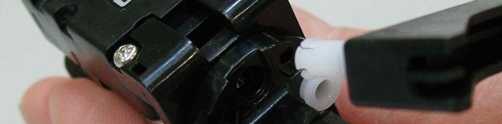
. Before insert front horn to smart servo, check the chase mark as the below.")
19 2.3 Right LEG Assembly Foot Frame Smart Servo * 4 (ID 06, 07, 08, 09) W Cable * 1 Knee Frame * 1 Front Horn * 1 Joint Frame * 2 U Frame * 1 Screw (P6) * 1, Bolt (B12) * 1 Bolt(B27)*4, Bolt (B35) *5, NUT * 10 3s rivet * 2 2s rivet * 8 STEP1. Insert front horn to smart servo ID09, then fix it with screw (P6). Before insert front horn to smart servo, check the chase mark as the below. Front horn chase mark should be in center position (12 o clock direction) Be careful that smart servo initial position should not be rotated when you put screw into front 19


20 STEP2. Insert 2s rivet to the Joint Frame to connect with Front Horn. STEP3. Connect W Cable into smart servo ID09 first, then connect foot frame by using Bolt and Nut. (Left) Foot Frame and (Right) Foot Frame is same. 20


21 STEP4. Connect W Cable (that is already connected with ID09) with smart servo ID08 and ID07. STEP5. Connect ID09 and ID08 by using 3s rivet. Rotate W Cable one time and fix it. 21

 and")


22 STEP6. Use the Bolt (B35) and Nut to connect ID08 and ID07 with Knee Frame. STEP7. Twist cable 3~4 times between ID08 and ID07 and put into empty space. 22


23 STEP8. Connect ID06 and U frame by using Bolt (B27) and Nut. Then use the 2s rivet to fix with Joint Frame. NUT Be careful JOINT frame direction STEP9. Connect ID07 with Joint Frame by using 3s rivet. Rotate W cable two times and connect to ID06. 23
 *5, NUT * 10 3s rivet * 2 2s rivet * 8 STEP1. Connect Front Horn to smart servo ID04 by using screw (P6).")
24 2.4 LEFT LEG Assembly Foot Frame Smart Servo * 4 (ID 01, 02, 03, 04) W Cable * 1 Knee Frame * 1 Front Horn * 1 Joint Frame * 2 U Frame * 1 Screw (P6) * 1, Bolt (B12) * 1 Bolt(B27)*4, Bolt (B35) *5, NUT * 10 3s rivet * 2 2s rivet * 8 STEP1. Connect Front Horn to smart servo ID04 by using screw (P6). Front horn chase mark should be in center position (12 o clock direction) 24


 and Nut.")
25 STEP2. Connect Front Horn and Joint Frame by using 2s rivets. Be careful with Joint Frame direction. STEP3. Insert W Cable with ID04, then connect Foot Frame by using Bolt(B12, B27) and Nut. W Cable connection to ID04 NUT connect position 25
26 STEP4. Connect W Cable with ID03 and ID02. STEP5. Connect Joint Frame with ID03 by using 3s rivet. Then, rotate W Cable1~2 times and fix it. 26
. Then use the 2s rivet to fix with Joint Frame.")
27 STEP6. Connect ID03 and ID02 with Knee Frame by using Bolt (B35) and Nut. Then, rotate the W Cable 3~4 times and put into empty space. STEP7. Connect ID01 and U frame by using Bolt (B27). Then use the 2s rivet to fix with Joint Frame. NUT Be careful JOINT frame direction 27


28 STEP8. Connect ID02 and Joint Frame by using 3s rivet. Then, rotate W Cable two times and connect with ID01. 28
29 2.5 RIGHT ARM Assembly 3*6 L type Frameⅹ2 Smart Servoⅹ2(ID14, ID15) U Frame x 2 Joint Frameⅹ1 3s rivetⅹ1 2s rivetⅹ12 Bolt (B27) x 4, NUT x 4 STEP1. Make Hand part by using the two 3*6 L type Frame and 2s rivets as shown in the below. Becareful with 3*6 L type Frame part direction because the both sides are not same. 29


30 STEP2. Connect ID15 and U Frame by using Bolt (B27) and Nut, then connect with Hand part by using 2s rivets. STEP3. Connect ID14 and U Frame by using Bolt (B27) and Nut, then, connect with Joint Frame. Be careful of Joint Frame direction when you connect with smart servo. 30


31 STEP4. Connect Joint Frame that connected with ID14 and ID15 by using 3s rivet. 31


 U Frame x 2")

 x 4, NUT x")


32 2.6 LEFT ARM Assembly 3*6 L type Frameⅹ2 Smart Servoⅹ2(ID11, ID12) U Frame x 2 Joint Frameⅹ1 3s rivetⅹ1 2s rivetⅹ12 Bolt (B27) x 4, NUT x 4 STEP1. Make Hand part by using the two 3*6 L type Frame and 2s rivets as shown in the below. Becareful with 3*6 L type Frame part direction because the both sides are not same. 32


33 STEP2. Connect ID12 and U Frame by using Bolt (B27) and Nut, then connect with Hand part by using 2s rivets. STEP3. Connect ID11 and U Frame by using Bolt (B27) and Nut, then, connect with Joint Frame. Be careful of Joint Frame direction when you connect with smart servo. 33


34 STEP4. Connect Joint Frame that connected with ID14 and ID15 by using 3s rivet. 34


35 2.7 BODY Assembly Body Frameⅹ1 Smart Servoⅹ4(ID00, ID05, ID10, ID13) W Cable x 2 3*6 L type Frameⅹ2 Front Hornⅹ4 Joint Frameⅹ4 U Frameⅹ2 3*3 Frameⅹ1 3s rivetⅹ8 2s rivetⅹ20 double rivetⅹ10 IRⅹ1 Smart Controllerⅹ1 Li-Poly Batteryⅹ1 Charging Board*1 Screw(P6)ⅹ4, Bolt (B6)ⅹ2, Bolt (B27)ⅹ4, Bolt (B30)ⅹ4, Nutⅹ10 STEP1. Connect Front Horn to ID05 by using screw (P6). Front horn chase mark should be in center position (12 o clock direction) 35


36 STEP2. Connect Front Horn and Joint Frame by using 2s rivet as the below. STEP3. Connect Front Horn and Joint Frame with ID00 same as the ID05 connection. Front horn chase mark should be in center position (12 o clock direction) 36


37 STEP4. Connect ID00 and ID05 with Body Frame by using Bolt (B27) and Nut. Check the ID05 and ID00 connect position well as shown in the below. 37


38 STEP5. Connect Front Horn with ID10. Check the Front Horn and ID00 mark position. - Smart servo mark position is 11 o clock while Front Horn mark position is 12 o clock as shown in the below. STEP6. Connect Joint Frame with Front Horn by using 2s rivets as shown in the below. 38


39 STEP7. Connect Front Horn with ID13. Check the Front Horn and ID00 mark position. - Smart servo mark position is 1 o clock while Front Horn mark position is 12 o clock as shown in the below. STEP8. Connect Joint Frame with Front Horn by using 2s rivets as shown in the below. 39


.")


40 STEP9. Connect U Frame with ID10 as shown in the below and connect with Body Frame by using Bolt (B30). STEP10. Connect U Frame with ID13 as shown in the above and finish the RQ HUNO shoulder. 40


")


 into")
41 STEP11. Assemble Head part. Connect 3*3 frame with Body Frame by using Bolt (B6) and Nut. 3*3 frame STEP12. Connect IR (Infrared Sensor) into 3*3 frame by using double rivets.. 41


42 STEP13. Connect 3*6 L type frame onto chest part. STEP14. Connect ID00 with ID01 and ID05 with ID06 by using 3s rivet, respectively. Then, pull the Cable outside from inside as shown in the below. 42
43 STEP15. Connect ID10 with ID11, and ID13 with ID14 by using 3s rivet, respectively. STEP16. Put the first connector of W Cable into ID12, and rotate W Cable 1~2 times then put the second connector of W Cable into ID 11 as shown in the below. 43
44 STEP17. Then, put the third connector of W Cable into ID 10. Put the fourth connector of W Cable Inside, then connect with ID00. STEP18. Put the first connector of W Cable into ID15, and rotate W Cable 1~2 times then put the second connector of W Cable into ID 14 as shown in the below. 44


45 STEP19. Put the third connector of W Cable into ID13, and put the fourth connector of W Cable into ID05. STEP20. Arrange the W Cabe as shown in the below, and pull out the W Cable from the bottom side of Body Frame to upside. 45


46 STEP21. Insert four 3s rivets to Body frame to fix Smart Controller as shown in the below. STEP22. Insert two double rivets to Body frame to fix Battery as shown in the below. 46


47 STEP23. Put Battery to Body Frame as shown in the below. STEP24. Connect W Cable and fix Smart Controller with Body Frame as shown in the below. 47


48 STEP25. Connect battery connector, then also connect power cable of charing board to the Smart Controller power connector as shown in the below. STEP26. Assembly completed. 48


")


49 2.8 Check Assembled Robot <Basic Posture> Let s find out how Robot works after assembly. Firstly, power on (press button P ) in smart controller. Then, press stop button of IR remote controller towards IR remote controller receiver. IR remote controller receiver Then Robot will take the basic posture as shown in the below. 49


50 <Attention Posture> Robot will take the Attention! posture if you press button 1 in IR remote controller. l Please check the assembly guide from the STEP1 again if robot posture is not the same as shown in the above. 50


 Prepare zero position tool.")
 Put FrontHorn into smart servo to be adjusted.")

51 3. Zero Position Adjustment Zero position is robot standard posture information in order to know the difference of each robot basic posture. Every robot basic posture would be different a little because every smart servo has own tolerance. For instance, A robot motion would play a little bit different in B robot because of smart servo tolerance. This difference can be reduced as you ajdust zero position adjustment. <RQ-HUNO zero position adjustment? FrontHorn mark i) Prepare zero position tool. ii) Fix Front Horn with zero position tool by using 2s rivets. standard line iii) Put FrontHorn into smart servo to be adjusted. Stand line and FrontHorn mark should be matched as the below. L mark zero position tool is to adjust robot left arm and left leg. R mark zero position tool is to adjust robot right arm and right leg. iv) Make power-off the smart controller. v) Press button P while button 1 pressed. ð LED 1 blue and red LED lights, also, smart servo ID00 blue LED lights. (Zero position adjustment starts from smart servo ID00.) 51


 Press button P to save the zero position. TIP. => Each smart servo is to be adjusted to conform with zero position adjustment line.")
52 vi) Press button 1 for selecting smart servo ID, then press button 2 or button 3 for smart servo rotating direction. Button 1 Button 2 Button 3 Every time you press button 1, smart servo is selected in order. ID01, ID02, ID03. ID15, ID00. Smart servo moves counter clockwise direction. Smart servo moves clockwise direction. For example, smart servo ID01 blue LED lighs when ID01 zero position adjustment is started. ð Make sure that 01 adjustment line is matched with smart servo ID means smart servo ID01. Adjust smart servo ID01 to fit with 01 number. vii) Press button P to save the zero position. TIP. => Each smart servo is to be adjusted to conform with zero position adjustment line. But for ID02, ID03, ID07, ID08 is to conform with Knee Frame, not a smart servo. => RQ-HUNO Body Frame should be conform with the rear side of Foot after zero position. 52


53 4. Download Cable (UART) driver Installation You need to install the download cable driver in order to use robot programming software, such as MotionBuilder, ActionBuilder, Diagnostic Tool and Firmware Upgrade Tool. 1) Download USB Download Cable Driver from and click to start installation. 2) Click I accept the terms of license agreement, then click Next. 53


54 3) Click Next and finish the installation as shown in the below.. 54

55 5. Download Tool 5.1 Introduction Download Tool is used for downloading a number of Motion files (*.rbm) or Action files (*.rba) at one time. Users can designate the download positions in remote controller. Layout description PC Port Connection Part. COM Port : Designate available COM port for connection of RoboBuilder.. BaudRate : It shows data transferring speed.. OpenPort : Open PC COM port in order to connect a RoboBuilder.. ScanPort : Find available COM port and opens it automatically. 55
56 5.2 Download File In RoboBuilder Download Tool, it shows the folders and downloaded (made) motion files. Click Delete All in order to delete the previous downloaded files in the list. In order to insert into Download File List section, select the file then, click > button. Users can use Drag & Drop function. 56


57 If you click a file in the Download File List, it shows file name, file size, robot platform, scene number, performance time. If registered files are more than one in the Download File List, users can change the downloading sequence by clicking Up or Down button. Users can do this function by using Keyboard. Up button = + Key Down button = - Key Delete button = Delete Key Connect RQ-HUNO and Download (UART) Cable as shown in the below. 57


58 Click ScanPort button in order to find available COM Port. RBC serial code and Firmware Version will be shown if connected properly. And ClosePort button will be shown as well. Click Download button, in order to all files in the Download File List. Then it starts downloading into RBC Box. Following message box will shown after downloaded completely. 58
 : A project file contains the information such as the robot s type and more. It is used to manage multiple motion files of a robot efficiently.")
59 6. MotionBuilder 6.1 Introduction This document explains how to use MotionBuilder the motion building tool for RQ-HUNO. What are project file, motion file, scene, frame, transition time? Project file(*.prj) : A project file contains the information such as the robot s type and more. It is used to manage multiple motion files of a robot efficiently. Therefore, one project file includes one or more motion files. Motion file(*.rbm) : A motion file contains the complete data to execute its movement. One motion file consists of multiple scenes. Scene : A scene is a smaller motion unit that constitutes a complete motion file. A scene consists of start position and destination position. Except the first scene, the start position of a scene is the destination position of its previous scene. When a scene is executed, the frame data is generated automatically according to the predefiend number of frames and delivered to each actuator modules. Frame : A frame is the smallest motion unit that constitutes a scene. Each frame can be considered as the still image that is actually sent to robot actuators. The more frames you define, the smoother the motion becomes. One scene can have from 1 up to 100 frames. Transition Time : Transition time is the time duration that is taken to execute a scene. Transition time is closely related with the number of frames. It can have value from 20msec up to 6000msec. The minimum transition time that can be allocated for a frame is 20msec. e.g) If scene A has 10 frames, the transition time can be selected from 200 up to

60 Screen Layout This is the screen layout of the MotionBuilder. 60


61 61
 Run MotionBuilder and click New. Input greeting in Project Name, then select Robot Platform RQ-HUNO.")
62 6.2 Motion Programming #1 Let s try one simple motion programming for RQ-HUNO. 1) Run MotionBuilder and click New. Input greeting in Project Name, then select Robot Platform RQ-HUNO. 2) Click OK, then it shows as below. 62
 4) Click Scan Port to search correct COM Port, or you can")

63 3) Connect RQ-HUNO with PC by using Down Cable (UART) then, power on smart controller (Button P) 4) Click Scan Port to search correct COM Port, or you can click Open Port if you know the COM Port No. 5) Click New Motion. Then input hi in Motion Name. If you want to use smart servo LED, check the Enable External Port, then, click OK. 63


64 6) If you see the New Scene window, click OK. You can adjust Frames, and Motion Run Time (ms). - Frames : If you increase the Frames, robot moves smoothly. -Motion Run Time : Each frame run time range is 20~1000msec. TIP. It is recommended that first scene and last scene is for robot basic posture for stable motion movement Therefore, do not revise the Frames and Run Time value of Scene0 7) In order to move up and shake the arm, add the second scene. For adding new scene, you should select next empty scene before click New Scene. 8) In order to move up and shake the arm, add the second scene. For adding new scene, you should select next empty scene before click New Scene. Move the Jog Dial of ID10. 64


65 9) Move the Jog Dial of ID11. 10) For the next movement, add the third scene. 11) Move the Jog Dial of ID12. 65

 Paste the Scene 1 and Scene 2 to")

66 12) Then, let s make the arm shaking motion like saying Hi. Copy the Scene 1 and Scene 2. 13) Paste the Scene 1 and Scene 2 to the next empty scene space, and do the paste again. Lastly, copy the Scene 0 and paste to the last scene. 66


67 14) Save the Motion file, Click select All and then click Test button. 15) Completed Hi.rbm motion movement is as follows.. 67
 in the previous motion 1) If you look at the scene part, you can see all the frame value is 30")

68 6.3 Change Motion Speed Let s find out about frame and motion run time. We have applied basic frame and motion run time (30 frames, 1000 msec) in the previous motion 1) If you look at the scene part, you can see all the frame value is 30 and time value is you can change the frames and time as you double-click related scene. 2) Minimum motion run time is 20msec for each frame. Therefore, time value should be at least 600 msec if frames are 30. Change the frame value first, then input proper time value. 3) Try to change the frame value to 15, and time value is 300msec then click Test as shown below. 4) You can see that motion speed is faster than before. 68

 Click New Motion, then input")
69 6.4 Motion Programming #2 In this section, we will make a deep bow HUNO motion. 1) Click New Motion, then input motion name as a deep_bow. 69
 Click Get Pose, you can see Motor Enable window, then")
70 2) Click New Scene to add new scene. 3) Click Get Pose, you can see Motor Enable window, then check Check All. 70
 as shown in the below.")
71 4) Then, you can make the RQ-HUNO posture by using your hand (Not by Jog Dial) as shown in the below. 5) Then, click Capture to complete the above scene. 71
 Click Get Pose, you can see Motor Enable window, then")
72 6) Click New Scene to add new scene. 7) Click Get Pose, you can see Motor Enable window, then check Check All. 72


73 8) Then, you can make the RQ-HUNO posture by using your hand (Not by Jog Dial) as shown in the below. 9) Then, click Capture to complete the above scene. 10) Now, Copy the Scene_1 to ready get up. 73

 Copy the Scene_0 to take a basic")
 Mouse right click, then space")
74 11) Mouse right click, then paste-insert to the next empty scene space after Scene_2. 12) Copy the Scene_0 to take a basic posture. 13) Mouse right click, then paste-insert to the next empty scene space after Scene_1 74


75 14) Now, click Select All and then click Test. 15) Click Save to save a deep_bow.rbm file. 16) deep_bow.rbm motion is downloaded successfully. 75
 Press button 1 of IR")
 Completed Hi.")
76 17) Click Close Port to control RQ-HUNO by IR remote controller 18) Press button 1 of IR remote controller, deep_bow.rbm motion is played. 19) Completed Hi.rbm motion movement is as follows. 76

77 7. ActionBuilder 7.1 Introduction ActionBuilder is the robot action programming software that uses various sensors of robot. Layout. 1 Menu Bar - New File : Create new action file. - Open : Load existed action file. - Save : Save action file. - Save As : Save action file with new name. - Config : Revise action file information. - Download : Download action file to RQ smart controller 2 PC COM Port - COM Port : Choose correct COM Port. - Baudrate : Display data communication speed. - OpenPort : Open COM Port connect PC with RQ HUNO. - ScanPort : Scan correct COM Port automatically. - Config : Revise action file information. 3 Action Information - Action Name : Display action file name. - Robot Platform : Display action file robot platform. - Total Statements : Display action file line numbers. 77
78 4 Action list - Index : Display action line index. - St. Name : Display statement name. - Condition : Display condition data. - Execution : Display execution data. - Description : Display description of statement. 5 Action Information - Statement Name : Display statement name and user can revise it. - Description : Display description of statement. - Add : Add action statement from list - Delete : Delete action statement from list. - Update : Update action statement from list. 6 CONDITIONS [If] - None : No condition - Distance : Distance condition (unit : cm, 10~50cm) - Sound : Sound condition (0~255, General clapping sound value is 10~15) - Touch, IR : Input from button - Remocon : Input from IR / Joystick remote controller - Accel : Input X,Y,Z acceleration value 7 EXECUTIONS [Then] - None : No execution - Motion Out : Run motion - Sound Out : Run sound - Wait Time : Wait for designated time. - Jump Index : Jump to designated index. 78


79 7.2 Action Programming #1 (Continuous Motions) - Robot Action : Basic Posture => Go => Back => Left => Right. 1) Click New to create new action file, then input Action Name, File Name and select RQ-HUNO platform as the below. 2) Connect RQ-HUNO with PC by using Down Cable (UART) then, power on smart controller. 3) Click Open Port. 79
 by number to add robot basic")
 Click as the below procedures")
80 4) Click as the below procedures (1,2,3,4,5) by number to add robot basic posture motion.. 5) Click as the below procedures (1,2,3,4,5) by number to add robot go motion. 80
 by number to add robot back")
 For Left and Right motion, it is same")
 Click below procedures (1,2,3) to save")
81 6) Click as the below procedures (1,2,3,4,5) by number to add robot back motion. 7) For Left and Right motion, it is same procedures except Motion Play section. 8) Click below procedures (1,2,3) to save action file and download to RO smart controller. 81
 7.3 Action Programming #1 (Using Sound Sensor) - Robot Action : Ready => If applause detected, move forward 82")
82 9) Press # + 1 of IR remote controller, then robot moves Basic Posture => Go forward=> Backwards => Move Left => Move Right) 7.3 Action Programming #1 (Using Sound Sensor) - Robot Action : Ready => If applause detected, move forward 82
 Click as the below procedures (1,2,3,4,5) to add basic posture motion.")
83 1) Click New to create new action file, then input Action Name, File Name and select RQ-HUNO platform as the below. 2) Click as the below procedures (1,2,3,4,5) to add basic posture motion. 83
 to detect applause sound and")
 Click as the below procedures")
84 3) Click as the below procedures (1,2,3,4,5) to detect applause sound and add go forward motion. 4) Click as the below procedures (1,2,3,4,5) to be in infinite loop state. 84

85 5) Click below procedures (1,2,3) to save action file and download to RO smart controller. 6) Press # + 2 of IR remote controller, then clap near RQ smart controller. 85
 Power-off the smart controller. 2) Press button 3 and then, press button P concurrently. LED3 \"Green, Blue and Red\" light up. 3) You can adjust the power-saving entry time as shown in the below.")
86 8. Appendix 8.1 Auto power-saving mode If there is no input or movement during certain time, RQ-HUNO goes into power-saving mode automatically. You can set the entry time as below. 1) Power-off the smart controller. 2) Press button 3 and then, press button P concurrently. LED3 "Green, Blue and Red" light up. 3) You can adjust the power-saving entry time as shown in the below. 4) Press Button P to save current setting after selecting power-saving entry time. 86
 Connect single smart servo")
 Make sure that Smart Controller")
87 8.2 How to change Smart Servo ID Number 1) Connect single smart servo cable as shown in the below. 2) Make sure that Smart Controller power is OFF state. 87


88 3) Press Button P as Button 1 and Button 3 are pressed together. You can see LED 1 is BLUE light. LED2 and LED3 indicates current Smart Servo ID. Yo You can change Smart Servo ID by pressing Button 1 or Button 3. - Button 1 is to increase Smart Servo ID number. - Button 2 is to cancel Smart Servo ID changes. - Button 3 is to decrease Smart Servo ID number. 4) Press Button P to save current Smart Servo ID after change ID number. 88


89 8.3 How to charge 89
Warning : If user does not follow the instructions in this book properly, a serious injury, harm,
 Safety Instructions Warning : If user does not follow the instructions in this book properly, a serious injury, harm, or death may occur to user. Caution : If user does not follow the instructions in this
Action Builder Manual
 Action Builder Manual July 31 st, 2008 ROBOBUILDER < T I T L E > 1. What is the Action Builder? 1 2. Screen Layout 1 3. Creating a New Action File (example: Creator HUNO) 3 4. Transferring an Action File
SCRATCH BUILDER R Q R O B O T C O D I N G G U I D E
 SCRATCH BUILDER R Q R O B O T C O D I N G G U I D E Scratch is developed by the Lifelong Kindergarten Group at the MIT Media Lab. See http://scratch.mit.edu1 W W W. R O B O B U I L D E R. N E T 01 INSTRALLATION
Motion Builder Tutorial
 Motion Builder Tutorial 2008.07.07 RoboBuilder MotionBuilder Tutorial 2/57 1. Before beginning 3 1.1. Document purpose 3 1.2. Things to prepare 3 1.3. What are project file, motion file, scene,
EQUIPMENT OPERATION MANUAL
 EQUIPMENT OPERATION MANUAL Loctite S440 Series SCARA Robots Book 2 of 4: Quick Start A Company FOR SAFE USE Safety Notes Read the following Warnings and Cautions thoroughly for the safe use of the Scara
Appbot RILEY. APPBOT Riley User Manual. IN THE BOX. Appbot RILEY. Charging Station Adapter USB Cable Manual
 Appbot RILEY www.rileyrobot.com APPBOT Riley User Manual IN THE BOX Appbot RILEY Charging Station Adapter USB Cable Manual [Caution] Be sure to use the supplied adapter and cable. 1) Install Application
Instruction Manual
 Waterproof Bluetooth USB Rechargeable Water Sport and Swimming Headphones PSWBT7 www.pyleaudio.com Instruction Manual READ THIS MANUAL CAREFULLY BEFORE USING THE BLUETOOTH HEADSET. Congratulations on purchasing
EQUIPMENT OPERATION MANUAL
 EQUIPMENT OPERATION MANUAL Loctite 200, 300, and 400 Series Benchtop Robots Book 1 of 4: A Company FOR SAFE USE Safety Notes Read the following Warnings and Cautions thoroughly for the safe use of the
User Manual. GUARD STATION(Gate View System) CDS-4GS
 CDS-4GS") User Manual GUARD STATION(Gate View System) CDS-4GS Thank you for purchasing COMMAX products. Please carefully read this User s Guide (in particular, precautions for safety) before using a product and
User Manual GUARD STATION(Gate View System) CDS-4GS Thank you for purchasing COMMAX products. Please carefully read this User s Guide (in particular, precautions for safety) before using a product and
YOOSTAR Owner s manual
 YOOSTAR Owner s manual Everything YOO need to know about your YOOSTAR ENTERTAINMENT SYSTEM Yoostar Owners Manual booklet.indd 1 4/16/09 9:22:15 AM Contents Getting Started... What s included... Unpack
THE BULLET. Bluetooth Speaker with NFC Technology. Instruction Manual
 Bluetooth Speaker with NFC Technology Instruction Manual Dear Customer, Thank you for purchasing an IRC product. We are pleased that you have chosen one of our products. At the same time, we are confident
Operation Manual WARNING. Be sure to read this Operation Manual before use. Universal Space Amusement Equipment Ltd.
 WARNING Be sure to read this Operation Manual before use. Universal Space Amusement Equipment Ltd. CONTENTS 1. The company..2 2. Specifications.. 3 3. Package Contents..5 4. Installation, Fix and Transport..6
Technical @Makeblock D1.2.11_
 Technical support: tec-support@makeblock.com www.makeblock.com @Makeblock @Makeblock @Makeblock D1.2.11_7.40.4600 The Modular & Programmable Drone USER MANUAL Table of Contents P02 Downloading the Software
OV1001 Part No OV1001 HEIGHT ADJUSTABLE TABLE USER GUIDE
 OV1001 Part No. 23620 OV1001 HEIGHT ADJUSTABLE TABLE USER GUIDE PRODUCT OVERVIEW User Guide: OV1001 OV1001 HEIGHT ADJUSTABLE TABLE A healthier work environment starts with the option to sit or stand throughout
aframe electrorganic percussion Quick Start Guide
 aframe electrorganic percussion EN JA Quick Start Guide Important safety information Failure to observe the following safety directives may result in fire, electric shock, injury, or damage to the aframe
User Manual VIDEO DOOR PHONE
 User Manual VIDEO DOOR PHONE CAV-35GN Thank you for purchasing COMMAX products. Please carefully read this User s Guide (in particular, precautions for safety) before using a product and follow instructions
OV1000 Part No OV1000 HEIGHT ADJUSTABLE TABLE USER GUIDE
 OV1000 Part No. 23624 OV1000 HEIGHT ADJUSTABLE TABLE USER GUIDE PRODUCT OVERVIEW User Guide: OV1000 OV1000 HEIGHT ADJUSTABLE TABLE A healthier work environment starts with the option to sit or stand throughout
Kogan Bluetooth Karaoke System with Dual Microphones KAKAR2MICA
 Kogan Bluetooth Karaoke System with Dual Microphones KAKAR2MICA K TABLE OF CONTENTS SAFETY & WARNINGS...1 IMPORTANT SAFETY INSTRUCTIONS...1 AC CONNECTION...2 LOCATION OF CONTROLS...3 ASSEMBLY AND CONNECTIONS...4
Auto-Cutter (JM98901) User's Manual
 User's Manual") Auto-Cutter (JM98901) User's Manual -2- Contents Notice 3 SAFETY SIGNS that must be strictly observed! 5 1. Function 7 2. Main specifications of auto-cutter 7 3. Checking items inside the accessory box
Auto-Cutter (JM98901) User's Manual -2- Contents Notice 3 SAFETY SIGNS that must be strictly observed! 5 1. Function 7 2. Main specifications of auto-cutter 7 3. Checking items inside the accessory box
V 1.0 ISSUE DATE : Feb.17, 2011
 V 1.0 ISSUE DATE : Feb.17, 2011 The following safety precautions are given throughout this manual. They must be strictly followed to protect those who install, use or maintain this product as well as to
To Purchase This Game, Visit BMI Gaming Or Contact International Sales at (USA)
") The following safety precautions are given throughout this manual. They must be strictly followed to protect those who install, use or maintain this product as well as to protect players, visitors and
The following safety precautions are given throughout this manual. They must be strictly followed to protect those who install, use or maintain this product as well as to protect players, visitors and
COLOR VIDEO DOOR PHONE
 www.commax.in.ua COLOR VIDEO DOOR PHONE.in.ua Model No. CDV-72BE a513-11, Sangdaewon-dong, Jungwon-gu, Seongnam-si, Gyeonggi-do, Korea Int l Business Dept. Tel.; : +82-31-7393-540~550 Fax.; +82-31-745-2133
PRECAUTIONS FOR USE. Be sure to use indoor wiring within the specified voltage requirements. For extension cord, use the specified rating or more.
 PRECAUTIONS FOR USE WARNING Be sure to consult an industry specialist when setting up, moving or transporting this product. This product should not be set up, moved or transported by any one other than
CHAPTER 2: USING MANAGER PREFERENCE. 2.1 Using Manager Mode Using CSAFE Console (back side) Access Layout...
 Access Layout...") S3x_OM_090507.indd 1 S3x_OM_090507.indd 2 CHAPTER 1: IMPORTANT SAFETY INSTRUCTIONS PAGES 1.1 Read and Save These Instructions... 01 1.2 Setting up the Stepper... 01 1.3 Installation Requirements... 01
S3x_OM_090507.indd 1 S3x_OM_090507.indd 2 CHAPTER 1: IMPORTANT SAFETY INSTRUCTIONS PAGES 1.1 Read and Save These Instructions... 01 1.2 Setting up the Stepper... 01 1.3 Installation Requirements... 01
Removal and Installation8
 8 Screw Types 8-4 Top Cover Assembly 8-5 Left Hand Cover 8-6 Right Hand Cover 8-10 Front Panel Assembly 8-14 Left Rear Cover 8-15 Right Rear Cover 8-16 Extension Cover (60" Model only) 8-17 Media Lever
Home Network. .in.ua. User Manual. Video Door Phone CDV-40N.
 Home Network User Manual Video Door Phone CDV-40N Thank Thank you you for for purchasing purchasing COMMAX COMMAX products. products. Please Please carefully carefully read read this this Userʼs Userʼs
For Sales + Purchasing Info, Click Page To Visit BMI Gaming (800)
") For Sales + Purchasing Info, Click Page To Visit BMI Gaming www.bmigaming.com + 561-391-7200 (800) 746-2255 The following safety precautions are given throughout this manual. They must be strictly followed
For Sales + Purchasing Info, Click Page To Visit BMI Gaming www.bmigaming.com + 561-391-7200 (800) 746-2255 The following safety precautions are given throughout this manual. They must be strictly followed
7 Digital Photo Frame
 7 Digital Photo Frame Instruction manual L7DPF17 12 month manufacturer's warranty -------------------------------------------------------------------------- --------------------------------------------------------------------------
JANOME DESKTOP ROBOT JR2000N Series. Operation Manual. <Setup> For Qualified Installer ONLY
 JANOME DESKTOP ROBOT JR2000N Series Operation Manual For Qualified Installer ONLY Thank you for purchasing the Janome Robot. *Read this manual thoroughly in order to properly use this robot. Be sure
Motorized Curtain Tracks Progress 50 Motor Set
 Troubleshooting Before you decide that the trouble is a malfunction, perform the following check. Condition Not operating Unstable operation Moves adversely and in opposite direction Operation speed is
Please read this guide before using the printer
 PD-450/450W/480/480W User Guide Please read this guide before using the printer Safety Precautions Safety Precautions Denotes the possibility of serious injury or death Use only recommended power sources.
SERVICE MANUAL Yhu#614 pzz lgkh{laz UG\SGYWX]
![SERVICE MANUAL Yhu#614 pzz lgkh{laz UG\SGYWX]](/thumbs/90/101197437.jpg "SERVICE MANUAL Yhu#614 pzz lgkh{laz UG\SGYWX]") SERVICE MANUAL The following safety precautions are given throughout this manual. They must be strictly followed to protect those who install, use or maintain this product as well as to protect players,
SERVICE MANUAL The following safety precautions are given throughout this manual. They must be strictly followed to protect those who install, use or maintain this product as well as to protect players,
Available in 2.0MP, 4.0MP, 6.0MP and 8.0MP, with 2.8mm and 3.6mm lenses.
 Camera Quick Install Guide VDMINIIRCB Series Available in 2.0MP, 4.0MP, 6.0MP and 8.0MP, with 2.8mm and 3.6mm lenses. Thank you for purchasing a VDMINIIRCB Series CCTV Surveillance Camera. This Quick Install
To connect the AC adapter:
 Replacing the AC Adapter Replacing the AC Adapter 3 Plug the power cord into a wall outlet. The power indicator turns on. To connect the AC adapter: Connect the power cord to the AC adapter. Power indicator
INSTRUCTION MANUAL. Tel. Fax. +49 (0) 4154 / (0) 4154 / Internet.
 4154 / (0) 4154 / Internet.") INSTRUCTION MANUAL Tel. Fax. E-mail Internet Address +49 (0) 4154 / 80 83-0 +49 (0) 4154 / 80 83-20 info@camos-multimedia.com www.camos-multimedia.com CAMOS Europe GmbH Carl-Zeiss-Str. 3 D-22946 Trittau
INSTRUCTION MANUAL Tel. Fax. E-mail Internet Address +49 (0) 4154 / 80 83-0 +49 (0) 4154 / 80 83-20 info@camos-multimedia.com www.camos-multimedia.com CAMOS Europe GmbH Carl-Zeiss-Str. 3 D-22946 Trittau
INSTRUCTION MANUAL. * Design and Specifications are subject to change without notice. ver. 1.0 PRINTED IN KOREA
 INSTRUCTION MANUAL * Design and Specifications are subject to change without notice. ver. 1.0 PRINTED IN KOREA INSTRUCTION MANUAL Thank you for purchasing this product. For proper usage and application,
ZYX User Manual V Revision
 ZYX User Manual V.00 206.07.26 Revision Contents Warning and Disclaimer... 3 I. Product Introduction... 4 II. Product List... 5. Package Contents... 5 III. Mounting & Configuration... 6. Gimbal Controller
User manual. BookDrive. Automatic Page-turning Scanner
 User manual BookDrive Automatic Page-turning Scanner BookDrive User s Guide All rights reserved. 2005 Atiz Innovation Co., Ltd. Under the copyright laws, this manual may not be copied, in whole or in part,
Ctdigi.com. Instruction manual. Production by S & W Technology Labs
 Ctdigi.com Instruction manual Production by S & W Technology Labs I. Install app II. Guard camera Guard camera Introduction Accessory Sensor Scenario Guard 360 Introduction - Catalog - Install app Scenario
Smartphone Photo Printer Item No
 Smartphone Photo Printer Item No. 205984 Safety Precautions Safety Precautions Denotes the possibility of serious injury or death Please keep you away at least 20cm distance from printer when printing.
Available in 2.0MP, 4.0MP and 8.0MP variants
 Camera Quick Install Guide FBMINIIR Series Available in 2.0MP, 4.0MP and 8.0MP variants Thank you for purchasing a FBMINIIR Series CCTV Surveillance Camera. This Quick Install Guide covers basic setup,
User Manual COMMAX LOBBY PHONE
 User Manual COMMAX LOBBY PHONE DRC-703S Thank you for purchasing COMMAX products. Please carefully read this User s Guide (in particular, precautions for safety) before using a product and follow instructions
Model No. ET-JPF200BE
 Operating Instructions Floor Stand Kit Commercial Use Model No. ET-JPF200BE ET-JPF200WE ENGLISH FRANÇAIS ESPAÑOL DEUTSCH ITALIANO * The above illustration is of this product mounted to an optional projector.
Smartphone Photo Printer
 Smartphone Photo Printer Safety Precautions Safety Precautions Denotes the possibility of serious injury or death Please keep you away at least 20cm distance from printer when printing. Use only recommended
Installation Manual. 65 Interactive LED/LCD. Model: HILF65101 (64.56 )
") Installation Manual 65 (64.56 ) Model: HILF65101 65 Interactive LED/LCD QUICK SETUP GUIDE For further information, see the user manual. Please contact directly if you have questions on the use of the touch
Installation Manual 65 (64.56 ) Model: HILF65101 65 Interactive LED/LCD QUICK SETUP GUIDE For further information, see the user manual. Please contact directly if you have questions on the use of the touch
USER MANUAL INCLUDED IN THE BOX
 USER MANUAL INCLUDED IN THE BOX Steering Motor Motor Cables Electronic Control Box Emergency Stop Button 3m USB cable Power Cord (UK, EU or US plug end) Additional Extras GT Steering Wheel - 6 x M5x16
3700 SERIES USER MANUAL
 SAFETY GUIDE This manual contains the precautions necessary to ensure your personal safety as well as for protection for the products and the connected equipment. These precautions are highlighted with
USERS GUIDE MCX-VTH. VGA to HDMI Converter. Manual Number:
 USERS GUIDE MCX-VTH VGA to HDMI Converter i Manual Number: 151226 SAFETY INSTRUCTIONS Please review the following safety precautions. If this is the first time using this model, then read this manual before
MOBILE CONNECTOR - GEN 2 OWNER'S MANUAL
 MOBILE CONNECTOR - GEN 2 OWNER'S MANUAL UNITED STATES Contents Safety Information... 2 Save These Important Safety Instructions... 2 Warnings...2 Cautions...3 General Information... 4 Mobile Connector
Table of contents 2 / 19
 User manual ADT-48 Table of contents 1. Safety instructions... 3 1.1. FOR SAFE AND EFFICIENT OPERATION... 3 2. Introduction... 4 3. Key Features... 4 4. Control Panel and Functions... 5 5. Connector Configuration...
Table of Contents. 01 Handbook Overview Unboxing Pepper Preparing Pepper Operating Pepper Choosing Pepper ' s Location 19
 PEPPER HANDBOOK Table of Contents 01 Handbook Overview 04 1.1. Pepper Features 05 1.2. Postures and Pins 06 02 Unboxing Pepper 07 2.1. Removing Pepper from Box 08 2.2. Pins and Packaging 09 03 Preparing
Table of Contents. Federal Communications Commission (FCC) Statement...2
 Statement...2") Contents Table of Contents Federal Communications Commission (FCC) Statement...2 Important Safety Instructions...3 Chapter 1 Introduction Features...6 Package Contents...7 Front View and Controls...8 Installing
Contents Table of Contents Federal Communications Commission (FCC) Statement...2 Important Safety Instructions...3 Chapter 1 Introduction Features...6 Package Contents...7 Front View and Controls...8 Installing
If you have questions about your KCD-2000 and its operation, please contact technical support at
 This manual contains important information on safety measures and operational features of the KCD-2000 4-way counterfeit detector. Please read it carefully before operating your machine and keep it for
Wired Cycle Computer Instruction Manual
 Wired Cycle Computer Instruction Manual Contents: 1. Supply 2. Assembly / Instructions 3. Keys & Functions 4. Modes 5. LCD Display 6. Basic Operations 7. Wheel Size 8. General Settings 9. Reset 10. Battery
USERS GUIDE MCX-STH. 3G SDI to HDMI Converter. Manual Number:
 USERS GUIDE MCX-STH 3G SDI to HDMI Converter i Manual Number: 151226 SAFETY INSTRUCTIONS Please review the following safety precautions. If this is the first time using this model, then read this manual
FREEWAVE STRYKER LIGHTNING/MOTION TRIGGER. User Manual
 FREEWAVE STRYKER LIGHTNING/MOTION TRIGGER User Manual THANK YOU FOR CHOOSING VELLO The Vello FreeWave Stryker for Canon and Nikon is a 2-in-1 solution for intense light and infrared (IR) image triggering.
LED Commander 16/2 DMX controller. user manual
 LED Commander 16/2 DMX controller user manual Musikhaus Thomann Thomann GmbH Hans-Thomann-Strasse 1 96138 Burgebrach Germany Telephone: +49 (0) 9546 9223-0 E-mail: info@thomann.de Internet: www.thomann.de
Fixed Wireless Phone. User Manual
 Fixed Wireless Phone User Manual V1.0 Content 1. Introduction... 1 2. Important Information... 2 3. Dos & Don ts... 2 4. Views... 4 5 Key board Introduction... 4 6. Installation... 5 6.1 SIM card installation...
Taurus Super-S3 LCM. Dual-Bay RAID Storage Enclosure for two 3.5-inch Serial ATA Hard Drives. User Manual March 31, 2014 v1.2
 Dual-Bay RAID Storage Enclosure for two 3.5-inch Serial ATA Hard Drives User Manual March 31, 2014 v1.2 www.inxtron.com EN Table of Contents Table of Contents 1 Introduction... 1 1.1 Technical Specifications...
U S B T H R O T T L E Q U A D R A N T D E S K TO P C O N S O L E
 THE ULTIMATE FLYING MACHINE TM U S B T H R O T T L E Q U A D R A N T D E S K TO P C O N S O L E CONTENTS PRECAUTIONS AND WARNINGS 2 INTRODUCTION 3 HARDWARE INSTALLATION 4 SWITCHING QUADRANTS 5 CONFIGURE
TOP - 1. Instruction Manual. Version 1.0 Produced in Jan. 2004
 Version 1.0 Produced in Jan. 2004 Instruction Manual LCD monitor IV-08MP Thank you for purchasing the SHARP IV-08MP LCD monitor. Read this introductory instruction manual carefully to thoroughly familiarize
Handheld Video Magnifier
 Zoomax TM Snow Handheld Video Magnifier V1.1 1 Contents Description...3 Accessories...3 Compositions:...4 Operation...5 Battery installation...5 Charging the battery...6 Install short strap...6 Operation
User's Manual. Metapace L-22D. Label Printer Rev. 1.00
 User's Manual Metapace L-22D Label Printer Rev. 1.00 Table of Contents MANUAL INFORMATION & USAGE PRECAUTIONS... 3 1. CONTENT CONFIRMATION... 6 2. PRODUCT PARTS... 7 3. INSTALLATION & USAGE... 9 3-1 POWER
1 Quickstart Guide 1
 1 Quickstart Guide 1 Honey, I m Home! 2 Nucleus at a Glance Instant Video & Audio Calling Privacy & Security Connect with all your loved ones with ease, so home is just The Privacy Camera Shutter, Do Not
Two-door Access Controller
 Two-door Access Controller Quick Start Guide V1.0.0 Preface Overview This document elaborates on structure, installation, interface and wiring of two-door access controller. Symbol Definition The following
INSEBO2IRF 2.1MP 1080P IP Eyeball Camera with IR
 INSEBO2IRF 2.1MP 1080P IP Eyeball Camera with IR Quick Start Guide Version 1.0.0 Welcome Thank you for purchasing our Network camera! This user s manual is designed to be a reference tool for your system.
PL1500M LCD Monitor USER'S GUIDE.
 PL1500M LCD Monitor USER'S GUIDE www.planar.com Content Operation Instructions...1 Safety Precautions...2 First Setup...3 Front View of the Product...4 Rear View of the Product...5 Quick Installation...6
Installation Manual. Model: HILU Ultra HD Interactive Flat Panel Display
 Installation Manual Model: HILU750 '' Ultra HD Interactive Flat Panel Display QUICK SETUP GUIDE For further information, see the User Manual. Please contact HITACHI directly if you have questions on the
Robot Light V2. User Manual
 Robot Light V2 User Manual 2 Please read over this manual before operating the light. Introduction Unpacking: Thank you for purchasing the Robot Light V2. Every Robot Light V2 has been thoroughly tested
DECT CLIP UC-01 USER GUIDE
 DECT CLIP UC-01 USER GUIDE CONTENT GENERAL INFORMATION 1 ABOUT YOUR EASY CLIP UC-01 2 GETTING STARTED 3 HEADSET FEATURES 5-6 VOICE GUIDE MEMU 6-7 HOW TO SAVE NUM. TO QUICK MEMORY 7 WHAT THE LIGTHS MEAN
Single Kernel Grain Moisture Tester PQ-520. (type PQ ) Operating Instructions
 Operating Instructions") Single Kernel Grain Moisture Tester PQ-520 (type PQ-5205-1) Operating Instructions Single Kernel Grain Moisture Tester Safety Precautions Not following the safety precautions could cause an accident resulting
Single Kernel Grain Moisture Tester PQ-520 (type PQ-5205-1) Operating Instructions Single Kernel Grain Moisture Tester Safety Precautions Not following the safety precautions could cause an accident resulting
PA Series. Available in 6.0MP and 8.0MP
 Camera Quick Install Guide PA Series Available in 6.0MP and 8.0MP Thank you for purchasing a PA Series CCTV Surveillance Camera. This Quick Install Guide covers basic setup, installation and use of your
Digital Overhead Stirrer
 A Geno Technology, Inc. (USA) brand name Digital Overhead Stirrer Cat. No. BT1021 1-800-628-7730 1-314-991-6034 info@btlabsystems.com Thanks for choosing BT1021 Digital Overhead Stirrer. This operation
CONTENTS. 1. Preface Features Technical Specifications Application of Dummy Plate Usage of Connector & Roller...
 2 CONTENTS - RW-2601P Series Caution... 4 1. Introduction... 5 2. Features... 7 3. Technical Specifications... 7 4. Explanation of Frontal Aspect... 9 5. Test Mode...11 6. Set Mode... 14 7. Calibration
DP-152. Digital Picture Viewer. Instruction Manual. Please read this manual carefully before operation 152SX
 DP-152 Digital Picture Viewer Instruction Manual Please read this manual carefully before operation 152SX Precautions For Customer Use: Enter below the serial number that is located on the bottom of the
Angel Carousel. Operation Manual. Be Sure to. Read the Operation. Universal Space Amusement Equipment Ltd. Manual before Use
 Angel Carousel Operation Manual Be Sure to Universal Space Amusement Equipment Ltd. Read the Operation Manual before Use CONTENTS 1. The company 2 2. Specifications...3 3. Package Contents...4 4. Installation,
Prestigio P371 Users manual
 Prestigio P371 Users manual 1. IMPORTANT INFORMATION WARNING: TO PREVENT FIRE OR SHOCK HAZARD, DO NOT EXPOSE THIS MONITOR TO LIQUIDS OR MOISTURE. HIGH VOLTAGE EXISTS ON THIS MONITOR. DO NOT REMOVE THE
Thanks for shopping with Improvements! Lighted Canterbury Christmas Greenery Doorway Arch Item #548443
 Thanks for shopping with Improvements! Lighted Canterbury Christmas Greenery Doorway Arch Item #548443 IMPORTANT, RETAIN FOR FUTURE REFERENCE: READ CAREFULLY. PARTS LIST: 2 Metal Plate Stands 5 Greenery
Revo 120. User Manual
 Revo 120 User Manual GENERAL INFORMATION Congratulations, you have just purchased one of the most innovative and reliable lighting fixtures on the market today! The Revo 120 has been designed to perform
FengMi Wemax One Laser Projection TV
 FengMi Wemax One Laser Projection TV User`s Manual About electrical ground Transportation Use this device only with a compulsory grounding condition. It is recommended that you use the original packaging
HDCVI Compact Mobile Camera User s Manual
 HDCVI Compact Mobile Camera User s Manual Version 1.0.0 Table of Contents 1 General Introduction... 1 1.1 Overview... 1 1.2 Features... 1 2 Device Framework... 2 2.1 Structure Dimension... 2 2.2 Cable
1M23N RBT-1 Operation Manual
 1M23N19904 RBT-1 Operation Manual 1 Contents of RBT-1 Operation Manual 1. Introduction...7 1.1. When You Think It Is Operating Incorrectly 7 2. For Safe Use...8 3. List of Goods...10 4. Part Names and
Please refer to Page 3.
 C. Insert the accessory CD into computer and open the following path: CD-ROM drive Chinese SH and ST port software SundooPor t SundooPor t. exe; This software need not be installed, and you only have to
JanusRAID SA-6692J Hardware User Manual
 JanusRAID SA-6692J Hardware User Manual 42-30000-5067 SATA II JBOD enclosure Version 1.1 SA-6692J SATA II JBOD enclosure Hardware User Manual Table of Contents Preface... i Chapter 1 System Requirements
BAS H Series Programmer
 BAS H Series Programmer INSTRUCTION MANUAL Please read this manual before using the machine. Please keep this manual within easy reach for quick reference. Thank you very much for buying a BROTHER sewing
Users Manual OPN Pocket Memory Scanner
 Users Manual OPN 2001 Pocket Memory Scanner CAUTION: This user s manual may be revised or withdrawn at any time without prior notice. Copyright 2006 Opticon Sensors Europe B.V. All rights reserved. This
Auto-leveling Rotating Laser (RL430G)
") Auto-leveling Rotating Laser (RL430G) Congratulations on your choice of this Auto-leveling Rotating Laser. For the purpose of long-term use of this instrument, we suggest you to read this instruction manual
Auto-leveling Rotating Laser (RL430G) Congratulations on your choice of this Auto-leveling Rotating Laser. For the purpose of long-term use of this instrument, we suggest you to read this instruction manual
ROBOBUILDER MSRDS KIT
 ROBOBUILDER MSRDS KIT TITLE 1. RoboBuilder-MSRDS Kit Features 2. Main Components 3. Robot Kit Specification 4. MSRDS (Microsoft Robotics Developer Studio 2008) 5. VPL (Visual Programming Language) 6. RoboBuilder
Startup Guide C01
 Startup Guide 4012988-00 C01 Startup Guide English Where to Find Information........................ 2 Safety Instructions.............................. 4 Important Safety Instructions...........................
TA0139 USER MANUAL ARDUINO 2 WHEEL DRIVE WIRELESS BLUETOOTH ROBOT KIT
 TA0139 USER MANUAL ARDUINO 2 WHEEL DRIVE WIRELESS BLUETOOTH ROBOT KIT I Contents Overview TA0139... 1 Getting started: Arduino 2 Wheel Drive Wireless Bluetooth Robot Kit using Arduino UNO... 1 2.1. What
650/1000 Fresnel 650/1000 PC 300/500 Antihalo 300/500 Fresnel theatre spotlight. user manual
 650/1000 Fresnel 650/1000 PC 300/500 Antihalo 300/500 Fresnel theatre spotlight user manual Musikhaus Thomann Thomann GmbH Hans-Thomann-Straße 1 96138 Burgebrach Germany Telephone: +49 (0) 9546 9223-0
Operator s Manual. 3-D Scanning Probe. Warranty Safety Features Setup Operation. Please save this manual for future reference.
 Operator s Manual 3-D Scanning Probe Please save this manual for future reference. CAUTION: Read and follow all Safety Rules and Operating Instructions before using this product. LHR Technologies Inc.,
User Manual. 1U LCD Keyboard Drawer. KwikDraw - A Series. Manual. IT and Instrumentation for industry. - With KVM options - 15", 17, 19 screen size
 User Manual 1U LCD Keyboard Drawer KwikDraw - A Series - With KVM options - 15", 17, 19 screen size 1.1 Important Safeguards Please read all of these instructions carefully before you use the device. Save
CENTRALDS CDS-5D USER GUIDE!!!!!! CDS-5D User Guide. Version 1.2 June 2014!!!!!
 CDS-5D User Guide Version 1.2 June 2014 PAGE 1 / 13 Contents Introduction 3 Camera usages 3 Package contents 4 Camera operation and responsibility 5 Handling precaution 5 Nomenclature 6 Before start using
SLIMLINE DASH CAM Audio & Video Recorder
 SLIMLINE DASH CAM Audio & Video Recorder 1 EK142CAM INSTRUCTION MANUAL PLEASE READ ALL INSTRUCTIONS CAREFULLY AND RETAIN FOR FUTURE USE Getting Started Remove the Car Digital Video Recorder from the box.
i-reader User manual
 i-reader User manual Table of contents 1. Introduction...1 2. General description i-reader...1 3. Intended use...1 4. Safety and maintenance...1 5. Installing the i-reader...2 5.1 Power supply...2 5.2
Product parameters: Body size: 49x19x10mm Wristband size: 252mm Weight: 17,8g Screen: OLED Battery: Built-in rechargeable lithium battery Battery
 i7 HR Manual Product parameters: Body size: 49x19x10mm Wristband size: 252mm Weight: 17,8g Screen: OLED Battery: Built-in rechargeable lithium battery Battery capacity : 75 mah Data synchronization: Bluetooth
Thank you for purchasing the CHP Assembly Tool. In order to ensure maximum performance and
 Power Supply Instruction Manual Applicable Models: APS-301A, APS-351B, APM-301A, APM-301C Thank you for purchasing the CHP Assembly Tool. In order to ensure maximum performance and product life, please
SAFETY WARNINGS AND GUIDELINES
 1 SAFETY WARNINGS AND GUIDELINES Please read this entire manual before using this device, paying extra attention to these safety warnings and guidelines. Please keep this manual in a safe place for future
Turntable player with USB/SD/PC recording function. Model no: TT620 User s Manual
 Turntable player with USB/SD/PC recording function Model no: TT620 User s Manual READ THIS INSTRUCTION CAREFULLY BEFORE USE AND STORE IN A SAFE PLACE FOR FUTURE REFERENCE 1 Features Two-built-in stereo