MACHINEMATE. Product Guide
|
|
|
- Ashley Blake
- 6 years ago
- Views:
Transcription
1 MACHINEMATE Product Guide 0408
2 Table of Contents Capabilities Specifications Standard Features CNC Engines Accessories
3 MACHINEMATE
4 MACHINEMATE CNC Architecture All Software Runs on the Main PC Processor (Celeron 1 GHz+, Pentium 4 1.7Ghz+) Via Shared Memory D D E S M S o f t w a r e Third- Party Win2K Software Windows 2000 BIOS CAM Package CNC MMI Task C O M Win2K Real Time Scheduler DDE PLC Priority 1 IEC1131 DDE PLC Priority 2 IEC1131 COM SM COM SM COM SM COM SM CNC Interpreter Task1 CNC Interpolator Task 1 CNC Position Loop Task 1 CNC 8 CNC CNC 2 CNC 1 Real Time Tick H a r d w a r e VGA HDD LP Keybd FDD etc. PC Interfaces and Peripherals = Software Hook Digital Inputs and Outputs Analog Inputs and Outputs Third-Party PC Interface Cards Machine Interface, Sensors, and Actuators Analog and/or SERCOS Interface(s) Motors and Drives
5 MACHINEMATE - A CNC That is Truly Open CNC Functions Software Hardware MMI and COM CNC Kernel PLC MMI & CAM or Third-Party S/W Compile Cycles Ethernet CNC Kernel DDE Interface or Applications through Compile Cycles (C ++ ) Software PLC (IEC ) or Other Soft PLC or C ++ PC hardware PC Motherboard, Third-Party PC PCI Boards Third-Party PC PCI Boards Discrete I/O InterBus-S, Profibus, CAN Bus, DeviceNet via PCI Board Open Standards or Third-Party Standards Proprietary Components Provided by MACHINEMATE, INC. Drives SERCOS Protocol or Analog Drives SERCOS Board, Analog ± 10 V, Third-Party Drives (S or A)
6 MACHINEMATE CNC Series Application Technologies o HSC Drilling o 2½D Milling o 2½D Machining Center o 2½D HSC Milling o Multi-Station CNC Milling o Two-Axis Turning (Standard and Sub-Micron) o High Precision Turning o Diamond Turning (Nanometer) o Multi-Spindle Turning o Combined Milling/Turning o High-Precision Measuring Machines (3D-Probe or 3D Laser Scanner) o 2D Laser Cutting o 2D Laser Welding o 2D Plasma Cutting o Electrical Die Sinking o Electrical Wire Cutting o Glass Cutting o Glass Grinding o High Precision Aspherical Glass Grinding o Gear Hobbing o Electron Beam Welding o Five-Axis Milling (Includes Gantry Machines) o Five-Axis HSC Milling o Five-Axis Turbine Blade Milling o Five-Axis Laser Cutting o Five-Axis Laser Welding o Five-Axis Surface Treatment o Five-Axis Grinding o Five-Axis Wood Milling
7 MACHINEMATE CNC Series PERFORMANCE DATA Blocks per Second (ISO) Typical Position Loop Gain CNC Stations (standard/max.) Standard Number of Axes Maximum Number of Axes Dynamic Block Buffer [Blocks] NC Program Memory [KB/MB] (on CNC / on hard disk) PLC Memory [KB] Inputs/Outputs Base Max. Base Max. Base Max. Base Max. MACHINEMATE Windows 2000 CNC Model L2 or ecnc H L2 or ecnc MM3 HS ecnc HSB /2 L2: 1/2, ecnc: 1/2 1/4 1/8 4(A)/8(S) 4(A)/8(S) 4(A)/8(S) L2:12(8S),eCNC:16 L2: 12(8S), 8(A)/8(S) ecnc: 32 64/64(A)/32(S) / / / / / / / L2S:24/16 else 48/32 L2S:24/16 24/16 else 48/32 48/32 792/ / /528 Note: A Analog Axes; S SERCOS Axes
8 MACHINEMATE CNC Series PERFORMANCE DATA Blocks per Second (ISO) Typical Position Loop Gain CNC Stations (standard/max) Standard Number of Axes Maximum Number of Axes Dynamic Block Buffer [Blocks] NC Program Memory [KB/MB] (on CNC / on hard disk) PLC Memory [KB] Inputs/Outputs Base Max. Base Max. Base Max. Base Max. MACHINEMATE Windows NT CNC Model MM1 MM3 MM5 MM /2 1/2 1/4 1/8 4(A)/8(S) 4(A)/8(S) 4(A)/8(S) 4(A)/8(S) 8(A)/8(S) 8(A)/8(S) 16(A)/32(S) 16(A)/32(S) / / / / / / / / /16 24/16 48/32 48/32 792/ / / /528 Note: A Analog Axes; S SERCOS Axes
9 MACHINEMATE CNC Series FACTS = Fast & ACcuraTe & Smooth - Components Geometry Look-Ahead Checks for violations of the established tolerance band during direction changes of the contour. Velocity and acceleration will be adjusted such that the tolerance band will not be exceeded. Dynamic Look-Ahead Checks during interpolation whether velocity or acceleration are exceeding the respective maximum values for the machine. The path velocity will be adjusted accordingly. Adaptive ART A self-adapting algorithm, which enables the feed forward function to achieve zero lag operation even in case of velocity changes on arcs, helix and spline. (ART=Advanced Regulation Technology) Adaptive Path Filter Checks for critical frequency ranges during the control process; limits resonances within the control loop in context with the path. Cubic Spline Interpolator Located between interpolator and position controller. Is based on cubic spline and introduces smooth acceleration transitions between points of interpolator and position controller. Ramp Function Linear ramps (for maximum productivity) are combined with smoothing through exponential behavior. This method yields highest productivity together with smooth acceleration.
10 Overview MACHINEMATE Functions (I) G 000 Rapid Traverse G 001 Linear Interpolation G 002 Circular Interpolation (clockwise) (circle center) G 003 Circular Interpolation (counterclockwise) G 012 Circular Interpolation (clockwise) (radius) G 013 Circular Interpolation (counterclockwise) G2/G3 Helical Interpolation G 004 Dwell in Milliseconds G 005 Spline Type G 006 Spline Interpolation (Refer to Specification, p. 29) G 007 Tangent Circle Interpolation Helical Interpolation Polygonial Interpolation Feedrate Interpolation G 008 Ramp at Block Transition Look Ahead Off G 009 No Ramp at Block Transition Look Ahead (23 Blocks) G 010 Stop Dynamic Block Pre-Processing G 011 Stop Interpolation During Block Pre-Processing G 014 Polar Coordinate Programming absolute G 015 Polar Coordinate Programming incremental G 016 Definition of Pole G 017 Plane Selection X, Y G 018 Plane Selection Z, X G 019 Plane Selection Y, Z G 020 Plane Selection, Programmable G 021 Parallel Axes On G 022 Parallel Axes Off G 024 Programmable Work Area, Lower Limits G 025 G 026 G 027 G 033 G 034 G 035 G 038 G 039 G 040 G 041 G 042 G 043 G 044 G 050 G 051 G 052 G 053 G 054 G 055 G 056 G 057 G 058 G 059 G 063 G 066 G 070 G 071 G 072 Programmable Work Area, Upper Limits Programmable Work Area Off Programmable Work Area On Programmable Thread Cutting, Constant Lead Thread Cutting, Variable Lead Prepare Oscillation Programmable Mirror Image On Programmable Mirror Image Off Tool Radius Compensation Off Tool Radius Compensation Left of Path/Intersection Tool Radius Compensation Right of Path/Intersection Tool Radius Compensation Left of Path/Perpendicular Tool Radius Compensation Right of Path/Perpendicular Scaling Part Rotation; Programming in Degrees Part Rotation; Programming in Radians Zero Offset Cancel Zero Offset 1, Per Axis Zero Offset 2, Per Axis Zero Offset 3, Per Axis Zero Offset 4, Per Axis Zero Offset 5, Per Axis Zero Offset 6, Per Axis Feedrate/Spindle Override Deactivated Feedrate/Spindle Override Activated Inch Format Metric Format Interpolation with In-Position-Tolerance Off
11 Overview MACHINEMATE Functions (II) G 073 G 074 G 075 G 078 G 079 G 080 G 081 G 082 G 083 G 084 G 085 G 086 G 087 G 088 G 089 G 090 G 091 G 092 G 093 G 094 G 095 G 096 G 097 G 098 G 100 G 101 G 102 G 103 G 104 Interpolation with In-Position-Tolerance On Programmable Referencing Curvature Approach to Contour On (With Rotary Axis Orientation) Approach to Contour Off Canned Cycle Off Canned Cycle Drilling Canned Cycle Facing with Dwell Canned Cycle Deep Hole Drilling Canned Cycle Tapping with Floating Holder Canned Cycle Reaming Canned Cycle Boring Canned Cycle Reaming with Stop for Gauging Canned Cycle Boring with Spindle Stop Canned Cycle Boring with Intermediate Stop Absolute Programming Incremental Programming Programmable Zero Shift Constant Circumference Speed On (Grinding Wheel) Feedrate Programming in mm/min Feedrate Programming mm/spindle Revolution Constant Cutting Speed On Constant Cutting Speed Off Positioning Axis Signal to PLC Polar Transformation Off Polar Transformation On, Cartesian Axis Letters Cylinder Transformation On, Cart. Coordinate System Cylinder Transformation On, w/real Time Radius Comp.(RRC) Cylinder Transformation w/profile Offset (PO) and RRC G 105 Polar Transformation On, Polar Axis Letters G 106 Cylinder Transformation On, Polar/Cylindrical Coordinates G 107 Cylinder Transformation On, Polar/Cyl. Coord. with RRC G 108 Cylinder Transformation On, Polar/Cyl. Coord. w/po & RRC G 109 Axis Transf., Programming of Tool Cutting Depth G 110 Power Control, Axis Selection/Channel 1 G 111 Power Control, Pre-Selection V1, F1, T1/Channel 1 G 112 Power Control, Pre-Selection V2, F2, T2/Channel 1 G 113 Power Control, Pre-Selection V3, F3, T3/Channel 1 G 114 Power Control, Pre-Selection T4/Channel 1 G 115 Power Control, Pre-Selection T5/Channel 1 G 116 Power Control, Pre-Selection T6/Pulsing Output G 117 Power Control, Pre-Selection T7/Pulsing Output G 120 Axis Transf.; Change Orient. of Rotary Axis for Linear Intpl. G 121 Axis Transf.; Change Orientation In One Plane G 125 Electronic Gearbox; Straight Teeth G 126 Electronic Gearbox; Slant Teeth, Axial G 127 Electronic Gearbox; Slant Teeth, Tangential G 128 Electronic Gearbox; Slant Teeth, Diagonal G 130 Axis Transf.; Progr. Mode of Orientation Change G 131 Axis Transf.; Progr. Mode of Orientation Change G 132 Axis Transf.; Progr. Mode of Orientation Change G 133 Learning Mode Threading without Lag On G 134 Learning Mode Threading without Lag Off G 135 Distance Control, Axis Selection G 140 Axis Transformation; Work piece Coordinates G 141 Axis Transformation; Active Coordinates
12 Overview MACHINEMATE Functions (III) G 160 Activate ART G 210 Power Control, Axis Selection/Channel 2 G 161 ART Learning Function for Velocity Parameters On G 211 Power Control, Pre-Selection V1, F1, T1/Channel 2 G 162 ART Learning Function Off G 212 Power Control, Pre-Selection V2, F2, T2/Channel 2 G 163 ART Learning Function for Acceleration Parameters On G 213 Power Control, Pre-Selection V3, F3, T3/Channel 2 G 164 ART Learning Function for Acceleration Changes On G 214 Power Control, Pre-Selection T4/Channel 2 G 165 Path Filter On G 215 Power Control, Pre-Selection T5/Channel 2 G 166 Path Filter Off G 270 Turning Finish Cycle G 170 Digital Probing Signals; Block Transfer with Hard Stop - G 271 Stock Removal in Turning (Stops and Backs Up) G 272 Stock Removal in Facing G 171 Digital Probing Signals; Block Transfer without Hard Stop - G 310 Power Control, Axis Selection/Channel 3 (Measures on Fly) G 311 Power Control, Pre-Selection V1, F1, T1/Channel 3 G 172 Digital Probing Signals; Block Transfer with Soft Stop G 312 Power Control, Pre-Selection V2, F2, T2/Channel 3 G 175 SERCOS Ident Number Write G 313 Power Control, Pre-Selection V3, F3, T3/Channel 3 G 176 SERCOS Ident Number Read G 314 Power Control, Pre-Selection T4/Channel 3 G 180 Axis Transformation Off G 315 Power Control, Pre-Selection T5/Channel G 181 Axis Transf. With Non-Rotated Coordinate System G 182 Axis Transf. With Rotated/Translated Coordinate System G 183 Axis Transf.; Definition of Coordinate System G 184 Axis Transf.; Programming Tool Dimensions G 186 Look Ahead; Corner Acceleration, Tolerance on Arc G 188 Activate Positioning Axes G 190 Diameter Programming Off G 191 Diameter Programming On and Display Tangent Point G 192 Diameter Programming Display Tangent Point Diameter G 193 Diameter Programming Display Tangent Point to Center Line G 200 Corner Rounding Off G 201 Corner Rounding On with Defined Radius G 202 Corner Rounding On with Defined Corner Deviation G 203 Corner Rounding On with Defined Radius up to Maximum Deviation
13 Overview MACHINEMATE Functions (IV) M 000 M 001 M 002 M 003 M 004 M 005 M 006 M 019 M 020 M 021 M 030 Unconditional stop Conditional stop End of program Spindle clockwise Spindle counterclockwise Spindle stop Spindle orientation M 040 Automatic spindle gear selection M 041 Spindle gear transmission step 1 M 042 Spindle gear transmission step 2 M 043 Spindle gear transmission step 3 M 044 Spindle gear transmission step 4 M 045 Spindle gear transmission step 5 M 046 Spindle gear transmission step 6 M 080 Tool change (see Note below) Oscillation On Oscillation Off End of program M 070 Spline, beginning and end curve 0 M 071 Spline, beginning tangential and end curve 0 M 072 Spline, beginning curve 0 and end tangential M 073 Spline, beginning and end tangential Delete the rest of distance using probe function Note: The M-code values for the machine-specific functions, for such features as coolant control, are specified in the PLC application. Their values are not defined by the CNC.
14 MACHINEMATE CNC SERIES SYSTEM SPECIFICATION
15
16 CONTENTS Page 1. INTRODUCTION MACHINEMATE ILLUSTRATION OPERATIONAL COMPONENTS OPERATION DISPLAY / DIAGNOSTICS AXES / AXIS FUNCTIONS MEMORY COMPENSATIONS PROGRAMMING INTEGRATED IEC SOFT PLC INTERNAL MACHINEMATE I/O ON SERCOS MODULE INTEGRATED PC COMMUNICATION SAFETY FUNCTIONS SYSTEM ACCESS MACHINEMATE FEATURES MECHANICAL OUTLINE OPERATING CONDITIONS MACHINEMATE, INC. reserves the right to change the specification or the performance without notice. Some features and options are future enhancements.
17
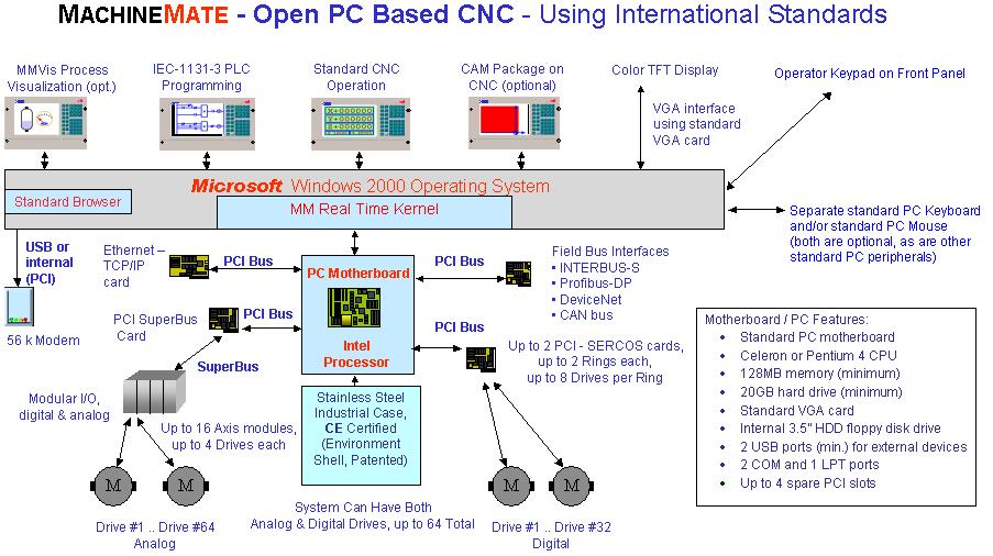
18 1. INTRODUCTION Superior Capability in Technology and Productivity The MACHINEMATE CNC provides you with innovative high-performance technology to handle the ever-increasing demands of today s automation industry. MACHINEMATE s modern and fully open CNC architecture, using a single, powerful Pentium CPU, gives you leading-edge CNC performance and flexibility. With MACHINEMATE, you do not sacrifice openness for CNC performance. There are good open architecture controls and good CNC controls on the market; but until MACHINEMATE, both did not exist in one single processor control. Modularity The MACHINEMATE CNC fulfills all technical requirements from standard to hightech applications. A variety of performance levels and technology functions is available. A high-performance CNC control does not have to be high-priced anymore. The compact and modular MACHINEMATE CNC provides you with the performance you need at an excellent price / performance ratio. Now you can have the openness of a PC in an industrial package that is enclosed in stainless steel with an IP65 rated front panel. To match the MACHINEMATE CNC to your requirements, four different performance levels are available as the economy version, the traditional version, the standard version and the plus version. A variety of hardware components such as a 10.4 or 12.1 TFT-display, different I/O components, ASCII drawer keyboard, and Teach-In Panel allow various customized configurations. Digital drives (SERCOS) or standard analog drives can be interfaced to MACHINEMATE. PC Technology The MACHINEMATE CNC is based on standard PC technology, integrated on an industrial level. Through the standard PC motherboard, with the powerful Pentium processor running the standard Windows 2000 operating system, plus our Real Time Kernel, the MACHINEMATE CNC is open to the PC components manufactured world wide. This way, a modern Windows 2000-based human machine interface was readily incorporated. As an option, a touch screen of 15 TFT color on the 19 rack mount front panel is available. Third party displays can be interfaced also since the front panel display cable is for the standard VGA. Moreover, there is the possibility to have 2 GB or more of NC program memory by means of PC hard disk technology. All types of communications ranging from Page 1/ 33
19 simple serial interfaces to a complex network environment are available. Aided by the standard PC operating system, you can integrate your own PC software such as NC programming tools, statistical programs, and visual programs in your control. A CNC That is Truly OPEN Based on a truly open architecture (including the CNC kernel), you can integrate, in a very secure and efficient manner, your application-specific knowledge and proprietary software routines written in C++ into the CNC. Your unique CNC functionality can be integrated into the CNC operating system with highly efficient software tools called Compile Cycles. In addition to such unique software, third-party PC-based hardware and software can be integrated due to the standard bus system (PCI) used. Application Experience and Know-how From two-axes turning, three-axes laser cutting to complex five-axes milling machines, the MACHINEMATE CNC fulfills a wide range of application requirements. A long list of standard functionality, including compensations, as well as high-tech functions such as five-axis transformation, make the MACHINEMATE an extremely versatile CNC. High-Speed Machining An important factor in machine tool productivity is the feedrate. New machine concepts and new tooling technologies require accurate and responsive controls with continuously increasing feedrates. Extremely short block cycle times (up to 2000 blocks/sec.) and specific control algorithms and communication functions are required for high-speed machining. Adaptive Look Ahead analyzes multiples of up to 1000 NC blocks ahead in real-time and calculates the maximum achievable feedrate for complex machining requirements staying within the programmed parameters and constraints. Accuracy The demands for increased productivity, higher accuracy, and better surface finish are continuously increasing. For higher accuracy and better part finish, the productivity of the machine tool should not be sacrificed. The MACHINEMATE CNC provides a solution to compensate for the machine kinematics, environmental conditions, and various other factors that cause errors in the machining process. With the MACHINEMATE and its software tool FACTS (Fast, ACcuraTe, and Smooth), you can achieve an optimum in accuracy, execution speed, and surface finish. ART (Advanced Regulation Technology) assists you in compensating path errors in real-time and reduces machine resonance when the feedrate is changed. During installation, ART automatically acquires the optimum parameters for each axis and compensates those parameters during the machining process as required. Page 2/ 33

20 Human Machine Interface Using six clearly defined modes of operation and a simple and clean-cut menudriven operation via soft keys, the machine operator will find the operation of the MACHINEMATE easy to learn and use. By means of the common window technology, the information is presented where it is needed on the screen. 2. MACHINEMATE ILLUSTRATION The picture shows the MACHINEMATE CNC package, including the CE-rated industrial PC (at the left), the 19 rack-mount IP65-rated front panel (in the middle), the front panel cables (at the lower left), remote IO boxes (at the right) and the complete software package. Page 3/ 33
21 3. OPERATIONAL COMPONENTS Operator s module Color flat TFT screen display 10.4 or 12.1" (See Figure 2.0) VGA (640 x 480, 10.4 ), SVGA (800 x 600, 12.1 ) Membrane keypad with short stroke keys Mode selection keys Soft keys Alphanumeric keypad 15 flat TFT touch screen in 19 rack mount panel (optional) Touch add-on to 12.1 display (optional) 9 monochrome CRT (optional) 4. OPERATION The MACHINEMATE CNC has six different operating modes that are selected by means of soft keys. Alternatively they may be selected through a pointing device, i.e., a cursor, a mouse, or alternative means. MANUAL Jog Continuously Traverse to Reference Point Auxiliary Functions AUTOMATIC Program Selection Program Test Path Graphics Backward DATA Selection Load Save Jog Incrementally Retreat (return to path) Jog with Hand Wheel Program Process 1 (Sequential, Single Block, MDI) Program Process 2 (Block Skip /, Optional Halt M01, Initial State) Edit Modify Manage INFORMATION Interface Display, CNC / PLC Version Page 4/ 33
22 Status Treatment Path Graphic of program in simulation (offline test) SYSTEM Display Functions Station (Channel) Selection Exit SETUP PLC Machine Parameters SERCOS Monitor I/O Configuration Log Book Operations Settings Minimize Drive Configuration Pitch Error Comp Gantry Initialize Logic Analyzer 5. DISPLAY/DIAGNOSTICS Display Languages Two display languages are selectable: English German Other Languages on Request NC Axis Information Position Direction Output Voltage Distance To Go Active Offsets Stored Data Information NC Programs Radius Compensation File Attributes Velocity Lag (Following Error) Position Loop Gain End Position Offset Values PLC Programs Tool Length Offsets Zero Offsets Status Information Auxiliary Functions Active Block Page 5/ 33
23 Active G Codes PLC Interface Active NC Program Status System Memory Memory Size for Both CNC and Windows System Memory Space Available Interfaces/Data Ports CNC PLC Interface Serial Interfaces* External Device Definition *May require additional software. User Information Box Error Messages in Legible Text Machine Parameters Legible Machine Parameters Edit Machine Parameters Active Subprogram Program Repetition Number of Part Programs Program Size PLC Machine Interface Serial Interface Setup* Time and Date Display Help Messages in Legible Text Input/Output of Machine Parameters Page 6/ 33
24 6. AXES/AXIS FUNCTIONS 4 Axes Simultaneous Interpolation is standard Choice of Analog Interface or Digital Interface (SERCOS) Analog SERCOS Measurement Input frequency 1 MHz (Internal 4 MHz) Depends on Drive Measurement Resolution Freely Selectable Freely Selectable Maximum Feedrate Resolution of 10 µm : 2,400 m/min Resolution of 1 µm : 240 m/min Resolution of 0.1 µm : 24 m/min Depends on Drive Output Signal ±10V DC, 5 ma Digital via Optical Fiber Cable 6.1 Axis Types Parallel axis logic Gantry axis logic Oscillation axis logic Rotary axis reset Spindle/rotary axis switchable PLC-driven axis 6.2 Transformations Five-axis transformation including helical-interpolation Four-axis transformation including helical-interpolation Three-axis transformation including helical-interpolation Polar transformation Barrel cam transformation Angled wheel transformation 6.3 Distance Control 3D distance control 6.4 Path Tracking 2D path tracking Page 7 / 33
25 6.5 Axis Control Velocity override via external analog signal Block processing control via external digital probe signals Adaptive Look Ahead 2½D and 3D Adaptive ART II 2½D and 3D 6.6 Axis Dependent Analog Output 3D Power control via axis channel 6.7 Electronic Gearbox 6.8 Positioning Axis Logic (for PLC-driven axis not a part program axis) Positioning axis logic for 200 NC blocks Positioning axis logic for 600 NC blocks 6.9 Spindle Control Without feedback With feedback Automatic gear step selection 6.10 Measurement Functions Probe logic (Probing routine available as an option) Software for distance encoded feedback 6.11 CNC Stations Up to 8 CNC stations with a maximum of 8 axes in each station 7. MEMORY NC Program Memory NC memory (buffered CMOS-RAM) 128 KB up to 872 KB NC programs 200 Program number Hard Disk Memory Hard disk memory NC programs Program number Page 8 / 33 6 Digits 800 MB Minimum Unlimited 6 Digits
26 Dynamic block buffer 50 Expandable to 1000 blocks PLC program memory 64 KB Expandable to 256 KB Cycle parameters 1000 Expandable to COMPENSATIONS Tool compensation Tool length compensation 128 sets Tool radius compensation 128 sets 3D cutter compensation Lead screw error compensation 4000, up to points Backlash compensation Zero offsets (or part offsets) External compensation via PLC Access to compensations via cycle programming 9. PROGRAMMING Subprograms (up to four levels) Automatic syntax checking Decimal point programming Compensation programming Programming simultaneous during program execution Teach-In function 9.1 NC Programming G codes G 000 G 001 G 002 G 003 G 012 G 013 G2/G3 G 004 Rapid traverse Linear interpolation with feedrate Circular interpolation (cw) Circular interpolation (ccw) Circular interpolation (cw) with radius Circular interpolation (ccw) with radius Helical interpolation Dwell time in millisecond Page 9 / 33
27 G 005 G 006 G 007 Spline definition Spline interpolation Tangential circular interpolation Helix interpolation Polygon interpolation Feedrate interpolation G 008 Ramping function at block transition Look ahead off G 009 No ramping function at block transition Look ahead on (23 blocks) G 010 G 011 G 014 G 015 G 016 G 017 G 018 G 019 G 020 G 021 G 022 G 024 G 025 G 026 G 027 G 033 G 034 G 035 G 038 G 039 G 040 G 041 G 042 G 043 G 044 Stop dynamic block preprocessing Stop interpolation during block preprocessing Polar coordinate programming, absolute Polar coordinate programming, relative Definition of the pole point Selection of the X, Y - plane Selection of the Z, X - plane Selection of the Y, Z plane Selection of a freely definable plane Parallel axes on Parallel axes off Safe zone programming; lower limit values Safe zone programming; upper limit values Safe zone programming off Safe zone programming on Thread cutting with constant pitch Thread cutting with dynamical pitch Oscillation activating Mirror imaging on Mirror imaging off Path compensations off Path compensation left of the work piece contour Path compensation right of the work piece contour Path compensation left of the work piece contour with altered approach Path compensation right of the work piece contour with altered approach Page 10 / 33
28 G 050 Scaling G 051 Part rotation; programming in degrees G 052 Part rotation; programming in radians G 053 Zero offset off (also called part offset or fixture offset) G 054 Zero offset #1 G 055 Zero offset #2 G 056 Zero offset #3 G 057 Zero offset #4 G 058 Zero offset #5 G 059 Zero offset #6 G 063 Feed / spindle override not active G 066 Feed / spindle override active G 070 Inch format active G 071 Metric format active G 072 Interpolation with precision stop off G 073 Interpolation with precision stop on G 074 Home position G 075 Curvature G 078 Normalcy function on (rotational axis orientation) G 079 Normalcy function off G 080 Drilling cycle off G 081 Drilling to final depth G 082 Spot facing with dwell time G 083 Deep hole drilling G 084 Thread cutting with balanced chuck G 085 Reaming G 086 Boring G 087 Reaming with measuring stop G 088 Boring with spindle stop G 089 Boring with intermediate stop G 090 Absolute programming G 091 Incremental programming G 092 Position register preset G 093 Constant tool circumference velocity on (grinding wheel) G 094 Feed in mm / min (or inch / min) Page 11 / 33
29 G 095 Feed per revolution G 096 Constant cutting speed on G 097 Constant cutting speed off G 098 Positioning axis signal to PLC G 100 Polar transformation off G 101 Polar transformation on G 102 Cylinder barrel transformation on ; cartesian coordinate system G 103 Cylinder barrel transformation on, with real-time-radius compensation (RRC) G 104 Cylinder barrel transformation with center line migration (CLM) and RRC G 105 Polar transformation on with polar axis characters G 106 Cylinder barrel transformation on polar-/cylinder-coordinates G 107 Cylinder barrel transformation on polar-/cylinder-coordinates with RRC G 108 Cylinder barrel transformation polar-/cylinder-coordinates with CLM and RRC G 109 Axis transformation programming of the tool depth G 110 Power control axis selection/channel G 111 Power control pre-selection V1, F1, T1/channel 1 G 112 Power control pre-selection V2, F2, T2/channel 1 G 113 Power control pre-selection V3, F3, T3/channel 1 G 114 Power control pre-selection T4/channel 1 G 115 Power control pre-selection T5/channel 1 G 116 Power control pre-selection T6/pulsing output G 117 Power control pre-selection T7/pulsing output G 120 Axis transformation; orientation changing of the linear interpolation rotary axis G 121 Axis transformation; orientation change in a plane G 125 Electronic gear box; plain teeth G 126 Electronic gear box; helical gearing, axial G 127 Electronic gear box; helical gearing, tangential G 128 Electronic gear box; helical gearing, diagonal G 130 Axis transformation; programming of the type of the orientation change G 131 Axis transformation; programming of the type of the orientation change G 132 Axis transformation; programming of the type of the orientation change G 133 Zero lag thread cutting on G 134 Zero lag thread cutting off Page 12 / 33
30 G 135 Distance control - axis selection G 140 Axis transformation; orientation designation work piece fixed coordinates G 141 Axis transformation; orientation designation active coordinates G 160 ART activation G 161 ART learning function for velocity factors on G 162 ART learning function deactivation G 163 ART learning function for acceleration factors G 164 ART learning function for acceleration changing G 165 Command filter on G 166 Command filter off G 170 Digital measuring signals; block transfer with hard stop G 171 Digital measuring signals; block transfer without hard stop G 172 Digital measuring signals; block transfer with smooth stop G 175 SERCOS-identification number write G 176 SERCOS-identification number read G 180 Axis transformation off G 181 Axis transformation on with not rotated coordinate system G 182 Axis transformation on with rotated / displaced coordinate system G 183 Axis transformation; definition of the coordinate system G 184 Axis transformation; programming tool dimensions G 186 Look ahead; corner acceleration; circle tolerance G 188 Activation of the positioning axes G 190 Diameter programming deactivation G 191 Diameter programming on and display of the contact point G 192 Diameter programming; only display contact point diameter G 193 Diameter programming; only display contact point actual axes center point G 200 Corner smoothing off G 201 Corner smoothing on with defined radius G 202 Corner smoothing on with defined corner tolerance G 203 Corner smoothing with defined radius up to max. tolerance G 210 Power control axis selection/channel 2 G 211 Power control pre-selection V1, F1, T1/Channel 2 G 212 Power control pre-selection V2, F2, T2/Channel 2 G 213 Power control pre-selection V3, F3, T3/Channel 2 G 214 Power control pre-selection T4/Channel 2 Page 13 / 33
31 G 215 Power control pre-selection T5/Channel 2 G 216 Power control pre-selection T6/pulsing output/channel 2 G 217 Power control pre-selection T7/pulsing output/channel 2 G 265 Distance regulation axis selection G 270 Turning finishing cycle G 271 Stock removal in turning G 272 G 274 G 275 G 276 Stock removal in facing Peck finishing cycle Outer diameter / inner diameter turning cycle Multiple pass threading cycle G 310 Power control axes selection /channel 3 G 311 Power control pre-selection V1, F1, T1/channel 3 G 312 Power control pre-selection V2, F2, T2/channel 3 G 313 Power control pre-selection V3, F3, T3/channel 3 G 314 Power control pre-selection T4/channel 3 G 315 Power control pre-selection T5/channel 3 G 316 Power control pre-selection T6/pulsing output/channel 3 G 317 Power control pre-selection T7/pulsing output/channel 3 M codes M 000 Unconditional stop M 001 Conditional stop M 002 End of program M 003 Spindle clockwise M 004 Spindle counterclockwise M 005 M 006 Spindle stop Tool change (see Note below) M 019 Spindle orientation M 020 Oscillation on M 021 Oscillation off M 030 End of program M 040 Automatic spindle gear selection M 041 Spindle gear transmission step 1 M 042 Spindle gear transmission step 2 M 043 Spindle gear transmission step 3 M 044 Spindle gear transmission step 4 Page 14 / 33
32 M 045 Spindle gear transmission step 5 M 046 Spindle gear transmission step 6 M 080 Delete rest of distance using probe function M 140 Distance regulation on (configured by G265) M 141 Distance regulation off Note: Other machine functions, like coolant control, have their M-code value specified by the PLC application, not by the CNC software. Programmable acceleration Tool management 9.2 Cycle Programming Programming tool with 1000 (up to 9999) parameters Allocation of parameters values with NC addresses Execution control of the NC program Output signal programming Verification of input signals Arithmetic and trigonometric functions Boolean programming functions Jump commands Repeat commands 9.3 CAM Software Capability Several CAM packages (and their post processors) are already configured to work with MACHINEMATE. The part program format follows the standard RS274D (with each field in the NC statement being a letter followed by a number; typical G-code and M-code part programming). Page 15 / 33
33 10. INTEGRATED IEC SOFT PLC Programming Languages Structured Text (included in basic) Ladder Diagram (included in basic) Function Block Diagram (optional) Instruction List (optional) Sequential Flow Chart (optional) Inputs Outputs PLC Memory Data Memory (non-retentive) Data Memory (retentive) Data type definitions C++ Routines Up to 792 MACHINEMATE Inputs Up to 528 MACHINEMATE Outputs 64 KB (expandable to 256 KB equiv. to 40,000 lines) 64 KB (expandable to 256 KB) Real, Integer, Timer, Boolean Variables 4 KB (expandable to 32 KB) Bit, Byte, Word, DWord, Real, LReal, SInt, USInt, Int, UInt, DInt, UDInt, String, Time, TOD, Date, DT, Arrays, enumeration, structures Custom Routines Written in C++ May Be Integrated Page 16 / 33
34 I/O Components The basic OEM MACHINEMATE system comes with a number of 24 volt inputs and 24 volt outputs of external I/O. The standard I/O supplied is MACHINEMATE Modular I/O, but external PLC I/O (Omron PLC IO but without a PLC processor) can be furnished as an option. With the MM1 and MM3 models, the control comes with 24 inputs and 16 outputs (i.e., one input module). With the MM5 and MM7 models, the control comes with 48 inputs and 32 outputs (i.e., two input modules). Field bus I/O (Profibus-DP or Interbus-S) can be used in conjunction with Modular I/O or PLC I/O or can be used exclusively. Either field bus is available as an option. External MACHINEMATE Modular I/O System Module Box: 24V Discrete Module: Relay Module: Analog Module: Encoder Module: Holds one or two modules, can be stacked laterally to each other and/or daisy-chained with cables, snaps on DIN rail 24 inputs, 16 outputs (1A) 24V DC 16 relay outputs (N.O.), 24V DC or 110VAC (3A) 4 analog in 12 bit, 4 analog out 14 bit 4 encoder inputs, 4 analog outputs, 4 analog inputs Each encoder input and analog output pair constitutes an analog drive interface (servo axis or spindle). The analog inputs are general purpose. Modular I/O system has built in line drivers and receivers for a remote arrangement, up to 115 ft.* (35 m) from the CNC. *Between control and last I/O module. Page 17 / 33
 When using SERCOS drives, an additional 24 DC inputs and 16 DC outputs @ 0.5 amps are available.")
35 MACHINEMATE Module Box 4.84 (123) H X 3.95 (100.4) W X 7.1 (181) D Dimensions: inches (mm) Dimensions do not include connectors. (a single 2416 IO module is shown above). 11. INTERNAL MACHINEMATE I/O ON SERCOS MODULE (does not apply to analog servo CNC model) When using SERCOS drives, an additional 24 DC inputs and 16 DC 0.5 amps are available. This I/O capability is in addition to the Modular I/O unit(s) included with the basic MACHINEMATE CNC. 12. INTEGRATED PC Industrial PC package (IPC) Intel processor (speed depends on model; is either Celeron or Pentium 4) 1.44 MB, 3.5" system floppy drive (in IPC) System hard disk, 2 GB minimum Windows 2000 MACHINEMATE Real Time Kernel Page 18 / 33
36 13. COMMUNICATION Interface Ports USB (at least 2) COM 1 and COM 2 (serial ports) Printer or LPT (parallel port) PS/2 Mouse Keyboard CD ROM (IDE) is available internally in the IPC Many standard PC devices could be connected externally via USB Data I/O Simultaneously with Program Execution LAN-Network (Ethernet) (optional) Standard PC network card (PCI) is optional Bus Interfaces (options) InterBus-S Profibus-DP DeviceNet CAN-bus 14. SAFETY FUNCTIONS Integrated Diagnostic Functions: Internal CNC voltage monitoring Processor activity Battery voltage monitoring for CMOS backup Electric noise monitoring Processor watchdog timer monitoring CMOS memory RAM memory Hard disk and floppy disk drives Bus systems Power supply voltage monitoring Temperature monitoring Operator guidance through soft keys Page 19 / 33
37 Syntax check during NC program inputs Checksum test Comprehensive CNC status and machine status display via PLC Read, write, and clear protection for NC programs Protected programs Password protection (up to ten levels) Software limit switches 15. SYSTEM ACCESS Via DDE technology All PLC variables (that can also include references to the CNC variables) can be referenced via a DDE (Dynamic Data Exchange). Any program using DDE technology, including many operator interface development applications or even spreadsheet applications such as Microsoft Excel, can access data with the MACHINEMATE. A visualizer program is also available, called MMVis. Graphical operator displays or windows can be created that access the PLC data in the MACHINEMATE using the DDE connection. Via MACHINEMATE Compile Cycles in C++ Basic software tools required (standard products from Microsoft, to be purchased by the customer): MS C++ Compiler, Visual C Development set: Compile cycle interface definitions Page 20 / 33
38 16. MACHINEMATE Features Representation of the Interface to Compile Cycles. Compile Cycles are dlls that are written by the customer; the dll is called by the CNC at specified events to work with the internal CNC data to adapt special algorithms or support special applications. Note: Basis represents the handling of the input NC blocks (i.e., the basis for the subsequent processing) IPO represents the CNC kernel s interpolator Position is the CNC position loop. PLC is the PLC application. Page 21 / 33
39 Five-Axis Transformation (Option) C Z Y A X Y-Wrist Offset Properties of the Five-AxisTransformation Definition of tool center point Definition of a speed limitation point on the tool Programming based on machine coordinate system Programming based on user-defined coordinate system TCP programming in the original coordinate system TCP programming in a rotated and shifted coordinate system Linear interpolation A, B, C axes Rotation of the tool vector in a plane Programming of the tool orientation by rotary axis positions or by vectors Page 22 / 33
40 3D DISTANCE CONTROL (Option) Laser Head Sensor Workpiece Distance Laser Tip / TCP Representation of Distance Control feature for Laser applications Page 23 / 33
41 ADAPTIVE LOOK AHEAD Adaptive Look Ahead F3 G09 F2 F1 G08 NC block sequence Adaptive Look Ahead results: Error-free block transitions. Adaptive Look Ahead analyzes up to several hundred subsequent NC blocks. Adaptive Look Ahead monitors the acceleration and deceleration values set for each axis. Adaptive Look Ahead assures that the dynamic limits of the machine will never be exceeded. Adaptive Look Ahead recognizes peaks in the velocity profile caused by geometry and F word changes. Acceleration and deceleration over multiple NC blocks. Continuous axis movement. Adaptive Look Ahead calculates the maximum path velocity with consideration of the programmed F word, the programmed accuracy, and the dynamic machine limits. Page 24 / 33
42 ADVANCED REGULATION TECHNOLOGY 1. Even with the most sophisticated feed-forward functions like the one of Machine Mate, Zero Following Error cannot be achieved completely, leaving a minute path error. Using the self-adapting ART function, this error can even be more reduced by automatic fine-tuning of the relevant control parameters. ART is included with all controls as a standard feature. 2. Below is the results of a machined and measured part that was completed on a Swiss Jig Grinder using circular interpolation. Excellent accuracies at high speed and small curvature were achieved. Part dia.:.984 (25 mm) Contouring velocity: 236 in./min. (5000 mm/min) Results (see figure below) Without ART: deviation from programmed circle:.0004 (0.01 mm) With ART: deviation from programmed circle: (0.002 mm, five times less error) Results Actual Path w/o ART Programmed Path Actual Path with ART Grid:.0002" (.005mm) With "Adaptive ART" Contouring without Servo Lag Adaptive ART learns the characteristics of all axes. Adaptive ART learns continuously. Adaptive ART supports the gain for movement in both directions. Adaptive ART compensates different gains of motors. Page 25 / 33
43 Adaptive ART uses: feedrate acceleration/deceleration acceleration/deceleration changes (jerk) Adaptive ART is active during: acceleration constant speed deceleration Page 26 / 33
44 LASER POWER CONTROL U(V) 10 V2 U(V) V2 V3 V1 V1 U1 U2 U3 U10 U0 F1 F2 U(V) Constant Velocity V3 V3 V2 V3 V1 Vakt L1 L2 L3 Position U0 U30 T1 T4 T2 T5 T3 Time ms Parameters = U Constant; F Velocity; L Position; T Time; V Power The figure represents different NC programs that select the different types of laser voltage output. Page 27 / 33
45 3D SPLINE INTERPOLATION Z Y X Real time spline interpolation NC data reduction by factor of 3 to 10 Tangential Smooth transitions In combination with five-axis transformation In combination with five-axis cutter compensation Page 28 / 33
46 17. MECHANICAL OUTLINES ecnc IPC All dimensions in inches (mm). The ecnc IPC weighs approximately 18.5 lb (8.4 kg). Page 29 / 33
47 L2 IPC The L2 IPC weighs approximately 24.5 lb (11.1 kg). Page 30 / 33
48 19 rack mount front panel with 12.1 TFT color display This front panel weighs approximately 11.0 lb (5.0 kg). The 19 rack mount front panel with the 15 color TFT touch display has the same outer dimensions and hole positions. It weighs 16.0 lb (7.3 kg). Page 31 / 33
49 Slim-line operator panel (two piece) This front panel weighs approximately 8.0 lb (4.0 kg). Page 32 / 33
50 18. OPERATING CONDITIONS Space Requirements Minimum installation free space is: left 3.2 (80), right 1.2 (30) Power Requirement 104V AC -132V AC; V AC - 244V AC 47Hz - 63 Hz Maximum Power Required 150 Watts Temperature Storage temperature -4 F to 140 F (-20 C to +60 C) Operating temperature 41 F to 113 F (5 C to 45 C) Test Conditions All MACHINEMATE controls are run-in tested for 48 hours by cycling between 41 F and 113 F (5 C and 45 C). Protection Operator s panel IP 65 Weight 29.5 lb (13.4 Kg) Basic OEM MACHINEMATE L2 with 12.1" TFT display in 19 rack-mount front panel Page 33 / 33
51 MACHINEMATE SERIES CNC STANDARD FEATURES INCLUDED IN THE BASIC OEM PACKAGE
52 MACHINEMATE BASIC CONFIGURATION 1. OPERATION The MACHINEMATE CNC has six different operating modes that are selected by means of soft keys. Alternatively they may be selected through a pointing device, i.e., a cursor, a mouse, or alternative means. MANUAL Move Continuously Traverse to Reference Point Auxiliary Functions AUTOMATIC Program Selection Program Test Path Graphics Backward DATA Selection Load Save Move Incrementally Retreat Hand Wheel Function Playback Program Process 1 (Sequential, Single Block, MDI) Program Process 2 (Block Skip /, Optional Halt M01, Initial State) Edit Modify Manage INFORMATION Interface Display Version Status Treatment Log Book SYSTEM Display Functions Station (Channel) Selection Exit Operations Settings Minimize MachineMate, Inc. reserves the right to change the specification or the performance without notice. Some features and options are future enhancements. Page 2 of 14
53 SETUP PLC Machine Parameters SERCOS Monitor I/O Configuration Drive Configuration Pitch Error Comp Gantry Initialize Logic Analyzer ZOOM Axis positions only are displayed, in much larger characters 2. DISPLAY/DIAGNOSTICS Display Languages Two display languages are selectable: English German NC Axis Information Position Direction Output Voltage Distance To Go Active Offsets Stored Data Information NC Programs NT/DOS Programs Radius Compensation File Attributes Status Information Auxiliary Functions Active Block Other Languages on Request Velocity Lag (Following Error) Position Loop Gain End Position Offset Values PLC Programs Tool Length Offsets Zero Offsets Active G Codes PLC Interface Page 3 of 14
54 Active NC Program Status Active Subprogram System Memory Memory Size for Both CNC and Windows System Memory Space Available Interfaces/Data Ports CNC PLC Interface Serial Interfaces* External Device Definition *May require additional software. User Information Box Error Messages in Legible Text Machine Parameters Legible Machine Parameters Edit Machine Parameters Program Repetition Number of Part Programs Program Size PLC Machine Interface Serial Interface Setup* Time and Date Display Help Messages in Legible Text Input/Output of Machine Parameters Page 4 of 14
55 3. AXES/AXIS FUNCTIONS 4 Axes Simultaneous Choice of Analog Interface or Digital Interface (SERCOS) Analog 4x SERCOS 8x Measurement Input frequency 1 MHz (Internal 4 MHz) Depends on Drive Measurement Resolution Freely Selectable Freely Selectable Maximum Feedrate Resolution of 10 µm : 2,400 m/min Resolution of 1 µm : 240 m/min Resolution of 0.1 µm : 24 m/min Depends on Drive Output Signal ±10V DC, 5 ma Digital via Optical Fiber Cable 4. COMPENSATIONS Tool Compensation Radius Compensations Length Compensations - Tool table for management of tool data Backlash Compensation Zero Offsets (G54 to G59) External Compensation via PLC Access to Compensations via Cycle Programming 5. SPINDLE CONTROL Through SERCOS or Analog CNC engine Analog Spindle Control via PLC is also possible (option - analog module) Page 5 of 14
56 6. COMMUNICATION Interfaces COM 1 Port COM 2 Port LPT 1 Port USB (at least 2 available) VGA external Display Port Keyboard Port CD ROM (IDE) Connector Mouse Port NC Format ISO (DIN 66025) (standard G-code, M-code programming) Data I/O Simultaneously with Program Execution File Load Main- and Subprograms Executable From Hard Disk 7. MEMORY Hard Disk - Number of NC Programs unlimited (to disk capacity) - Program Number 6 digits NC Program Memory 128 KB CMOS RAM - Number of NC Programs Program Number 6 digits (option increases to 224KB, 400KB or 872KB) Dynamic Block Buffer 50 blocks (option increases to 200 or 1000 blocks) PLC Program Memory 64 KB (option increases to 128KB or 256KB) Cycle Parameter Memory 1000 parameters (option increases in increments of 1000) Page 6 of 14
57 8. PROGRAMMING NC Programming as per ISO (DIN 66025) - G00 Rapid traverse - G01 Linear interpolation - G02/G03 Circular interpolation - G04 Dwell - G07 Tangential circle interpolation - G08/G09 Path control mode (ramp at block transitions) "Adaptive Look ahead" function - G10/G11 Block pre-processing control - G12/G13 Circular interpolation with radius input - G17-G20 Plane selection - G33 Thread cutting/rigid tapping - G38/G39 Mirror image - G40-G44 Tool radius compensation - G50 Scaling - G51/G52 Part rotation - G53-G59 Zero offsets - G63/G66 Programmable feed rate/spindle speed override - G70/G71 Inch/metric switching - G72/G73 Interpolation with in position stop - G74 Home position - G80-G89 Canned cycles - G90/G91 Absolute/incremental programming - G92 Position register preset (part reference) - G94/G95 Feedrate programming - G186 Programmable tolerance band - M00 Program stop - M01 Optional stop - M02/M30 End of program - M03/M04/M05 Spindle control - M06 Tool change - M19 Spindle orientation (programming options: see Product Guide section 2 for complete G-code list) Cycle Programming - Programming tool with 1000 parameters - Use of parameter values within NC addresses - Execution control of the NC program - Programmable man-machine interface - Input/output signal programming - Monitoring of input signals - Arithmetic and trigonometric functions - Boolean operators - Jump commands - Repeat commands Page 7 of 14
58 Subroutines (4 Levels) Automatic Syntax Check Decimal Point Programming Compensation Programming Programming Parallel to Program Execution Probing function - Automatic Position Value Acquisition 9. INTEGRATED SOFT PLC AS PER IEC Languages: PLC Memory Internal Flags Timers I/O Definition C Routines Structured Text (Standard) Ladder Diagram (Standard) 64 KB (expandable to 256KB, equiv. to 40,000 instr.) 256 (expandable to 1000) non retentive 256 (expandable to 1000) retentive 256 (expandable to 1000) non retentive 256 (expandable to 1000) retentive bit/byte, word, double word Custom routines written in C can be integrated via an external object library 10. INTEGRATED PERSONAL COMPUTER Integrated Personal Computer - Intel processor (varies with CNC model Celeron or Pentium 4) MB, 3½"-system floppy drive - TFT display graphics board - System hard disk - Microsoft Windows 200 operating system - MACHINEMATE real time kernel Page 8 of 14
59 11. SAFETY FUNCTIONS Following checks are integrated: - CNC voltage monitoring - Processor activity - Battery voltage monitoring for CMOS backup - Electrical noise monitoring - Processor watchdog timer monitoring - CMOS Memory - Feedback supervision - Feedback signal (incremental encoder) (broken wire detection) - RAM memory - Hard disk / floppy drive - Bus systems - Temperature monitoring Operator Guidance Through Soft Keys Syntax Check During NC Program Input Software Limit Switches CNC Status and Machine Status Display via PLC Read, Write, Delete and Execution Protection for NC Programs Protected Programs Password Protection (up to 10 levels) Page 9 of 14
60 The MACHINEMATE Milling or Turning application software must be specified at the time of purchase. Abbreviations in the following list are as follows: Package: item: M Milling package i included T Turning package o optional When an item is indicated as included for a major group, there is usually at least one option for that category. CNC STANDARD FEATURES DESCRIPTION M T COMMENTS 1. OPERATION Handwheel Interface i i 250 pulses per rev.; maximum of 3 handwheels (options include operator hardware) 2. DISPLAY / DIAGNOSTICS The color displays available are selected through the choice of the basic control type. The 10.4 color (VGA 800x600) flat panel display is standard in the slim line (2-piece front panel), whereas the 12.1 color (VGA 800x600) is standard in the 19 rack mount front panel. 9 monochrome CRT is optional replacement for 10.4 color in slim line front panel. 15 color touch display is optional in the 19 rack mount front panel. Flat TFT touch screen is available as an option in 12.1 size. 3. AXES / AXIS FUNCTIONS The basic control comes with 8-axes SERCOS or 4-axes analog (not both). Please specify which drive control interface is desired. Select Digital SERCOS Drive Interface (8 axes) i i SERCOS or Analog Axis Interface (4 axes) i i Analog (options include more axes and/or more stations or program paths) Page 10 of 14
61 DESCRIPTION M T COMMENTS Axis Types Parallel Axes Logic i i (options include gantry axes and other axis variations) Adaptive Look Ahead; 2½ D i i Adaptive ART II i i including Command Filter 2½ D Automatic Drift Compensation (analog) i i (options include other transformations, such as full 5-axis, polar, barrel cam, angled wheel; also electronic gear box for gear hobbers) 4. COMPENSATIONS Lead Screw Error Compensation 1,000 Internal Points i i (options include more points, up to 16000) 5. SPINDLE CONTROL Spindle Control (with or without feedback) i i Automatic Gear Step Selection (analog) i i (options include more spindles) 6. COMMUNICATION Floppy Disk Drive (A:), Front Access i i (options include external floppy drive or network card) 7. MEMORY EXTENSION NC Memory Extension (buffered CMOS RAM) i i (options include more memory) Page 11 of 14
62 DESCRIPTION M T COMMENTS 8. PROGRAMMING Cycle Programming Extension to 1000 Parameters i i (options: more available in increments of 1000) NC programming Helical Interpolation i o Spline Interpolation i o Feedrate Interpolation i o Diameter Programming o i Thread Cutting G33/G34 o i Rigid Tapping i o Constant Surface Speed o i Feed Per Revolution i i Polar Coordinate Programming i o Programmable Acceleration i o Safe Zone Programming i i Corner Rounding i i Tool Management i i Extended PLC Interface i i (options in most cases above: the optional item is usually associated with either a Milling or Turning application so it does not apply to the other application making it optional for that type) (other options include: software for non-servo clutch/brake machines, software for two-axes collinear tracking) Page 12 of 14
63 DESCRIPTION M T COMMENTS 9. PROBING FUNCTIONS Probing Logic (Probing routine is an option.) i i 10. MACHINEMATE MODULAR I/O* Module Box (for two I/O Modules) i i I/O Module 24-Input/16-Output (1A) 24 VDC i i (qty: see below) (for the L2 for analog drives, two modules are built-in; for all other models these are IO modules are optional) (SERCOS models come with additional 24i/16o connector) (options: Relay Module: 16 relays (N.O. contacts) Analog Module: 4 input channels/4 output channels; Axis Encoder Module: 4 analog axis channels) READY-TO-USE CABLES FOR MODULAR I/O Interconnect Cable ft. (2 m) i i (option: longer cables are available, up to 35m) (option, since the ecnc can be mounted on the back of the 19 rack mount front panel, a short 0.6m cable is available for that arrangement) (options: Fieldbus I/O can be supported as an option in place of or in addition to the Modular IO; available fieldbus PCI cards are: Interbus, Profibus, Canbus and DeviceNet; no Fieldbus IO devices are available other than the interface bus master card for the CNC) 11. PLC DEVELOPMENT ENVIRONMENT PLC IEC1131 Language i i (Ladder Diagram and Structured Text) PLC Development System on CNC i i (options: the other IEC-1131 standard languages: Instruction List (IL), Function Block (FB), and Sequential Flow Chart (SFC), individually) Page 13 of 14
64 12. DOCUMENTATION Installation Kit i i (includes MACHINEMATE Manuals on CD) (options: the printed manuals are available individually or as a set) Page 14 of 14
65 MACHINEMATE SERCOS CNC-ENGINE The SERCOS CNC-ENGINE board is specially designed to complement the powerful MACHINEMATE SERCOS software with the following features: G PCI Interface, 33 MHz G One or two independent SERCOS interfaces (i.e., 1 or 2 fiber-optic rings and 8 drives per ring, so either 8 or 16 drives per board) G Easy installation G SUPERBUS I/O Interface to MACHINEMATE Modular I/O pack(s) G 24 DC Inputs G 16 DC Outputs G RAM on board (battery buffered) G Watchdog (64ms) G Voltage Monitor G Temperature Supervisor G Ready relay G Power - OK relay G Diagnostic LEDs G Real-time clock generator G High flexibility through FPGA technology 1

66 SERCOS controller 1 CNC ready relay Battery RAM Temperature & ± 12V supervisor 2 diagnostic LEDs +5V monitor 24 x 24V DC inputs Fiber optical SERCOS 1 24V input/ output connector Connector for Power OK and CNC ready relay Real-Time clock generator Fiber optical SERCOS 2 16 x 24V DC outputs PCI connector SERCOS controller 2 Power OK relay SUPERBUS connector to I/O Serial Prom for FPGA FPGA with PCI interface PCI Interface SERCOS interface(s) Real - Time clock generator Easy installation SUPERBUS interface 32-bit bus with 33 MHz clock. The PCI interface complies with revision 2.1 of the specification. One or two independent SERCOS interfaces. Single chip controller for each SERCOS interface. Dual port RAM with 2048 bytes. Maximum transmission rate of 4 MBaud. Data communication via optical fiber ring. Power modulation of optical transmitter diode. Data transmission is synchronous to on board real-time clock. Special hardware for real-time kernel. Needed for absolute clock synchronous axis control. The software automatically configures interrupts and the integrated memory. I/O bus interface with a transfer rate of 4Mbit/s up to a maximum extension of 115 (35m). This interface is to the MachineMate Modular I/O devices. 24V DC inputs 24V DC outputs Memory Battery Watchdog Voltage monitor Power OK relay CNC ready relay Relay connector Hardware diagnostic LEDs FPGA technology Temperature supervisor Dimensions All inputs are opto-isolated. All outputs are opto-isolated source outputs. Output current can be 1A per channel (8A max. for all 16 outputs). Shorted load and over temperature protections. Under voltage shut down. 256 Kbyte (1 Mbyte opt.) battery buffered static RAM. On board Li, high capacity. Digital watchdog, programmable up to 64ms. + 5V and ± 12V supervisor for under- and over-voltage monitoring. Battery supervisor for under-voltage monitoring. One 24V / 1A relay, which switches on if both the power and temperature are OK. One 24V / 1A relay, which switches on if the control is in the ready state. The two relays are connected to the CNC electrical circuits via this 15-pin connector. Two LEDs show the ready and the power OK status. Third generation Field-Programmable Gate Array. The speed grade is fully PCI compliant. Linear PCI - Local bus interface, no address gaps. FPGA configuration via serial prom. 131 F (55 C) / 140 F (60 C) supervisor for temperature monitoring (135 mm) x 4.21 (107 mm) 2
67 MACHINEMATE SUPERBUS IO CNC-ENGINE The Superbus IO CNC-ENGINE board is specially designed to complement the powerful MACHINEMATE software with the following features: G PCI Interface, 33 MHz G Easy installation G SUPERBUS I/O Interface to MACHINEMATE Modular I/O pack(s), including the 4ENC4A module for the analog-controlled servo drives G RAM on board (battery buffered) G Watchdog (64ms) G Voltage Monitor G Temperature Supervisor G Ready relay G Power - OK relay G Diagnostic LEDs G Real-time clock generator G High flexibility through FPGA technology This card is similar to the SERCOS Engine card except it has no fiber-optic ring support and no 24in/16out IO connector. The drives are handled via the MIO 4ENC4A modules and the IO points in the system are handled via the MIO 2416 modules. 3

68 2 diagnostic LEDs Relays for Power OK and CNC Ready Battery Connector for Power OK and CNC Ready relays SUPERBUS connector to I/O FPGA with PCI interface PCI connector PCI Interface Real - Time clock generator Easy installation SUPERBUS interface Memory Battery Watchdog Voltage monitor Power OK relay CNC ready relay Relay connector Hardware diagnostic LEDs FPGA technology Temperature supervisor Dimensions 32-bit bus with 33 MHz clock. The PCI interface complies with revision 2.1 of the specification. Special hardware for real-time kernel. Needed for absolute clock synchronous axis control. The software automatically configures interrupts and the integrated memory. I/O bus interface with a transfer rate of 4Mbit/s up to a maximum extension of 115 (35m). This interface is to the MachineMate Modular I/O devices. The 4ENC4A axis interface module provides the CNC access to the analog-controlled servo drives. 256 Kbyte (1 Mbyte opt.) battery buffered static RAM. On board Li, high capacity. Digital watchdog, programmable up to 64ms. + 5V and ± 12V supervisor for under- and over-voltage monitoring. Battery supervisor for under-voltage monitoring. One 24V / 1A relay, which switches on if both the power and temperature are OK. One 24V / 1A relay, which switches on if the control is in the ready state. The two relays are connected to the CNC electrical circuits via this 6-pin connector. Two LEDs show the CNC ready and the power OK status. Third generation Field - Programmable Gate Array. The speed grade is fully PCI compliant. Linear PCI - Local bus interface, no address gaps. FPGA configuration via serial prom. 131 F (55 C) / 140 F (60 C) supervisor for temperature monitoring (135 mm) x 4.21 (107 mm) 4
 is included, with a 26-pin round connector G Emergency stop push button (push in to lock, twist out")
69 MACHINEMATE Accessories - MPG The Handheld Operator Station with handwheel (or MPG) from MACHINEMATE INC is specially designed to complement the MACHINEMATE control with the following features: G Dust and waterproof pendant G 3-meter flexible cable (polypropylene insulated, polyurethane jacket) is included, with a 26-pin round connector G Emergency stop push button (push in to lock, twist out to release) G Handwheel (manual pulse generator or MPG) with 100 counts per revolution, in either a 5V encoder model or a 24V input (signal pair) model G Axis selection switch (six positions: X, Y, Z, 4, 5, 6) G Feed selection switch (three position: X1, X10, X100) G Two general purpose push buttons (illuminated) G PLC application template for this MPG available from MACHINEMATE INC or from its web site There are four versions. There are two handwheels (either 5V encoder or a 24VDC signal pair). There are two cable lengths available. One version has a 4.26-foot cord, that extends to about 21-feet. The other version has a 5.9-foot cord, that extends to about 34- feet. 1
SYSTEM SPECIFICATION
 SYSTEM SPECIFICATION CNC Series PA 8000e PA Power Automation AG Tel.: ++49-(0) 7144-899-0 Gottlieb-Daimler-Straße 17/2 Fax: ++49-(0) 7144-899-299 D-74385 Pleidelsheim www.powerautomation.com Germany sales@powerautomation.com
Part Programming Manual MACHINEMATE
 MACHINEMATE NOTE Progress is an ongoing commitment at MACHINEMATE INC. We continually strive to offer the most advanced products in the industry. Therefore, information in this document is subject to change
List of ISO supported G-Codes and M-functions
 ARISTOTLE G-Codes List of ISO supported G-Codes and M-functions G-code Function G00 Travers motion and positioning G01 Linear interpolation G02 Circular interpolation CW G03 Circular interpolation CCW
MAIN TECHNICAL SPECIFICATIONS
 S4045P S4045P The S4045PD is suited for highspeed machines destined to mill complex surfaces. It is extremely fast and powerful and is equipped with the Intel PC CPU for the operator interface and also
ADVANCED TECHNIQUES APPENDIX A
 A P CONTENTS þ Anilam þ Bridgeport þ Fanuc þ Yasnac þ Haas þ Fadal þ Okuma P E N D I X A ADVANCED TECHNIQUES APPENDIX A - 1 APPENDIX A - 2 ADVANCED TECHNIQUES ANILAM CODES The following is a list of Machinist
9000 CNC 9000 CNC: THE NEW STANDARD OF CONTROL. INTUITIVE EFFICIENT PRODUCTIVE
 3D Solid Model Graphics Solid Model with Tool Path Overlay 9000 CNC 9000 CNC: THE NEW STANDARD OF CONTROL. At Milltronics we are constantly refining our controls to simplify operation, shorten setup times
Mach4 CNC Controller Mill Programming Guide Version 1.0
 Mach4 CNC Controller Mill Programming Guide Version 1.0 1 Copyright 2014 Newfangled Solutions, Artsoft USA, All Rights Reserved The following are registered trademarks of Microsoft Corporation: Microsoft,
Century Star Turning CNC System. Programming Guide
 Century Star Turning CNC System Programming Guide V3.5 April, 2015 Wuhan Huazhong Numerical Control Co., Ltd 2015 Wuhan Huazhong Numerical Control Co., Ltd Preface Preface Organization of documentation
Series 0ί -MD Mate CNC STANDARD FEATURES
 STANDARD FEATURES Axis Control Digital Servo Function 1 Controlled Path Simultaneously controlled axes: Up to maximum of 3 Serial Encoder Interface Axis Name Selected from X,Y,Z and U,V,W,A,B,C Spindle
Lesson 4 Introduction To Programming Words
 Lesson 4 Introduction To Programming Words All CNC words include a letter address and a numerical value. The letter address identifies the word type. The numerical value (number) specifies the value of
Our thanks go to: Puppy Linux, RTAI, EMC, axis, all the kernel developers and big mama thornton.
 CoolCNC Linux First Steps This manual is a step by step introduction for the installation of the CoolCNC Linux Live CD. Its intent is to lead to a better understanding of the current processes. This document
Mach4 CNC Controller Mill Programming Guide Version 1.1 Build 3775
 Mach4 CNC Controller Mill Programming Guide Version 1.1 Build 3775 Copyright 2014 Newfangled Solutions, Artsoft USA, All Rights Reserved The following are registered trademarks of Microsoft Corporation:
G & M Code REFERENCE MANUAL. Specializing in CNC Automation and Motion Control
 REFERENCE MANUAL Specializing in CNC Automation and Motion Control 2 P a g e 11/8/16 R0163 This manual covers definition and use of G & M codes. Formatting Overview: Menus, options, icons, fields, and
CNC Knee Type Milling Machines with USA CENTROID M-400S CNC control
 CNC Knee Type Milling Machines with USA CENTROID M-400S CNC control GMM-949-CNC, 9 x49 table, R8, vari-speed, 3 axis CNC... GMM-949F-CNC, 9 x49 table, R8, inverter drive, 5,000 rpm, 3 axis CNC.. Note:
Touch Control Panels. Precision Built Solutions
 Touch 2200 Control Panels Precision Built Solutions The Touch 2200 provides world class technology and advanced features not available in other controls proving that east-to-use does not have to mean compromising
CHAPTER 12. CNC Program Codes. Miscellaneous CNC Program Symbols. D - Tool Diameter Offset Number. E - Select Work Coordinate System.
 General CHAPTER 12 CNC Program Codes The next three chapters contain a description of the CNC program codes and parameters supported by the M-Series Control. The M-Series Control has some G codes and parameters
Up to 4-axis plus closed-loop spindle Conversational and G-Code programming in one control Systems for knee mills, bed mills and VMC s USB interface
 Up to 4-axis plus closed-loop spindle Conversational and G-Code programming in one control Systems for knee mills, bed mills and VMC s USB interface Acu-Rite 3500i boosts efficiency, versatility, touch
Mach4 CNC Controller Lathe Programming Guide Version 1.0
 Mach4 CNC Controller Lathe Programming Guide Version 1.0 1 Copyright 2014 Newfangled Solutions, Artsoft USA, All Rights Reserved The following are registered trademarks of Microsoft Corporation: Microsoft,
GE FANUC 21 CONCEPT 55 MILL ATC TEACHER GUIDE
 GE FANUC 21 CONCEPT 55 MILL ATC TEACHER GUIDE 11/1/07 Version 2 Made by EMCO Authored by Chad Hawk Training Index Control Keyboard Pg 1 Fanuc 21 Control Machine Control Fanuc 21 Screen. Pg 2 Fanuc 21 Keys.
Conversational Programming for 6000i CNC
 Conversational Programming for 6000i CNC www.anilam.com P/N 634 755-22 - Contents Section 1 - Introduction Section 2 - Conversational Mode Programming Hot Keys Programming Hot Keys... 2-1 Editing Keys...
MELDAS, MELDASMAGIC, and MELSEC are registered trademarks of Mitsubishi Electric Corporation. The other company names and product names are
 MELDAS, MELDASMAGIC, and MELSEC are registered trademarks of Mitsubishi Electric Corporation. The other company names and product names are trademarks or registered trademarks of the respective companies.
LabCenter 260. LabCenter 260. CNC Milling Machine. Compact Machine for Training Purposes and Small Batch Production - with Siemens control
 CNC Milling Machine Compact Machine for Training Purposes and Small Batch Production - with Siemens control Travel X-axis Y-axis Z-axis Spindle speed max. Tool changer 251 mm 152 mm 168 mm 5000 rpm 4 stations
GSK218M Milling Machine CNC System
 GSK218M Milling Machine CNC System GSK218M is widespread CNC system (matched with machining center and general milling machine) employed with 32-bit high performance CPU and super-large-scale programmable
Software designed to work seamlessly with your CNC Masters machine. Made to work with Windows PC. Works with standard USB
 Software designed to work seamlessly with your CNC Masters machine Made to work with Windows PC Works with standard USB Clutter free interface. The software is engineered for the machine so you don t have
SOFTWARE. CAD/CAM software. Interpreter software. Programming software. Software and control organization isy-cam 2.5 PLUS...
 SOFTWARE Software and control organization... 4-2 CAD/CAM isy-cam 2.5 PLUS... 4-4 Interpreter Remote... 4-5 Programming... 4-6 PAL-PC 2.1... 4-7 Software and controller organisation Software and controller
Welcome to. the workshop on the CNC 8055 MC
 Welcome to the workshop on the CNC 8055 MC Sales Dpt-Training: 2009-sept-25 FAGOR CNC 8055MC seminar 1 Sales Dpt-Training: 2009-sept-25 FAGOR CNC 8055MC seminar 2 This manual is part of the course for
CNC Machining Center. X.mill 640. with Touch-Screen Technology. Travel distances X axis 640 mm Y axis 400 mm Z axis 500 mm. X.
 CNC Machining Center with Touch-Screen Technology Travel distances X axis 640 mm Y axis 400 mm Z axis 500 mm The Power Package = compact, powerful, precise and very cost-effective! state-of-the-art GPlus
Conversational Programming for 6000M, 5000M CNC
 Conversational Programming for 6000M, 5000M CNC www.anilam.com P/N 70000486F - Contents Section 1 - Introduction Section 2 - Conversational Mode Programming Hot Keys Programming Hot Keys... 2-1 Editing
SOFTWARE. CAD / CAM software. Interpreter software. Programming software. Software and control organization... D-2
 SOFTWARE Software and control organization... D-2 CAD / CAM isy-cam 2.8... D-4 OneCNC... D-5 Mastercam... D-5 Interpreter Remote... D-6 Programming PAL-PC 2.1... D-7 ProNC... D-8 CAD/CAM OneCNC milling
software isy-cam 2.8 and 3.6 CAD/CAM software Features isy-cam 2.8 Features isy-cam 3.6 D-4 CAD functionality (without volume modeller)
") CAD/CAM isy-cam 2.8 and 3.6 isy-cam 2.8 CAD functionality (without volume modeller) works with Win XP, Windows 7 and 8, 32-/64-bit version Import: DXF / EPS / AI / 3D STL data Export: NCP format proven
CAD/CAM isy-cam 2.8 and 3.6 isy-cam 2.8 CAD functionality (without volume modeller) works with Win XP, Windows 7 and 8, 32-/64-bit version Import: DXF / EPS / AI / 3D STL data Export: NCP format proven
2LIST OF SPECIFICATIONS
 B 63522EN/02 GENERAL 2. LIST OF SPECIFICATIONS 2LIST OF SPECIFICATIONS : Standard : Standard option : Option : Function included in another option Note) The use of some combinations of options is restricted.
GE Fanuc Automation. Series 15 / 150 Model B for Machining Center. Computer Numerical Control Products. Descriptions Manual
 GE Fanuc Automation Computer Numerical Control Products Series 15 / 150 Model B for Machining Center Descriptions Manual GFZ-62082E/04 April 1997 Warnings, Cautions, and Notes as Used in this Publication
HAAS AUTOMATION, INC.
 PROGRAMMING WORKBOOK HAAS AUTOMATION, INC. 2800 Sturgis Rd. Oxnard, CA 93030 JUNE 1, 2000 JUNE 2000 PROGRAMMING CONTENTS INTRODUCTION... 1 THE COORDINATE SYSTEM... 2 MACHINE HOME... 5 ABSOLUTE AND INCREMENTAL
Polar coordinate interpolation function G12.1
 Polar coordinate interpolation function G12.1 On a Turning Center that is equipped with a rotary axis (C-axis), interpolation between the linear axis X and the rotary axis C is possible by use of the G12.1-function.
COPYCAT NEW FANGLED SOLUTIONS 2/6/2009
 1.0 INTRODUCTION 1.1 CopyCat is a unique wizard used with MACH3. It is not a stand alone program. This wizard will allow you to jog a machine around and create a Gcode file from the movement. 2.0 REQUIREMENTS
Programming Features PERFORMANCE & SPECIFICATIONS
 PERFORMANCE & SPECIFICATIONS Essentials Processor Intel Pentium Instruction Set 32-bit Performance Number of Cores 1 Processor Base Frequency 1.8 GHz Memory Data Storage 1 GB System Memory Installed 2
2. INTRODUCTION TO CNC
 Q. Define NC Machines. 2. INTRODUCTION TO CNC A method of automation, in which various functions and processing of machine tools are controlled by letters and symbols. The general objective of NC technology
X.mill 1100 L. X.mill 1100 L. CNC Machining Center. Control GPlus 450 with touch-screen technology or Siemens Sinumerik 828 D
 CNC Machining Center Control GPlus 450 with touch-screen technology or Siemens Sinumerik 828 D description specifications GPlus 450 siemens 828 D www. k n u t h -u s a. c o m Travel distances X axis 43
Product Information. POSITIP PT 8016 Digital Readout for Manually Operated Machine Tools
 Product Information POSITIP PT 816 Digital Readout for Manually Operated Machine Tools 11/218 POSITIP PT 816, PT 816 Active The convenient digital readout for milling, drilling, and boring machines, and
TF5xxx TwinCAT 3 Motion Control
 TF5xxx Motion Control TC3 NC PTP 10 Axes TC3 NC PTP Axes Pack 25 TC3 NC PTP Axes Pack unlimited Technical data TF5000-00pp TF5010-00pp TF5020-00pp TC3 NC PTP 10 Axes implements Motion Control for pointto-point
Turning ISO Dialect T
 SINUMERIK 802D Short Guide 09.2001 Edition Turning ISO Dialect T User Documentation SINUMERIK 802D Turning ISO Dialect T Short Guide 09.2001 Edition Valid for Control Software Version SINUMERIK 802D 1
Automation 3200-OEM/Nservo-OEM
 Automation 3200-OEM/Nservo-OEM Motion Controllers Automation 3200-OEM/Nservo-OEM 32-Axis Motion, Vision, Robotics, and I/O Platform Complete motion capabilities include: point-topoint; linear, circular,
527F CNC. Retrofit controller for machines made by Fadal Machining Centers. Installation and set-up manual Calmotion LLC
 527F CNC Retrofit controller for machines made by Fadal Machining Centers Installation and set-up manual 2008-2018 Calmotion LLC Calmotion LLC 7536 San Fernando Road Sun Valley, CA 91352 www.calmotion.com
KA3-6VS 300mm KA3-6VS 400mm Vertical Spindle
 Vertical KA3-6VS 300mm KA3-6VS 400mm Vertical Spindle The Kira KA3- Series of traveling column (3) Axis CNC Machining Modules are an excellent choice for special application machine builders. These modules
527F CNC. Retrofit controller for machines made by Fadal Machining Centers. Installation and set-up manual Calmotion LLC
 527F CNC Retrofit controller for machines made by Fadal Machining Centers Installation and set-up manual 2008-2018 Calmotion LLC Calmotion LLC 7536 San Fernando Road Sun Valley, CA 91352 www.calmotion.com
CNC. Modular, 64 axes IndraMotion MTX performance, IndraMotion MTX advanced
 Modular, 64 axes IndraMotion MTX performance, IndraMotion 2 Bosch Rexroth AG Electric Drives and Controls Documentation Broschures Software IndraMotion MTX performance & advanced the high-performance controls
ELECTRONICS. Controllers... C-2
 ... C-2 Overview Overview CNC control units C-3 iop 19-TFT iop 19-CPU Step controller Single axis controller C-4 IT 116 Flash Step controller Multiple axis controller C-5 imc-s8 Servo controller Single
CNC Programming Simplified. EZ-Turn Tutorial.
 CNC Programming Simplified EZ-Turn Tutorial www.ezcam.com Copyright Notice This manual describes software that contains published and unpublished works of authorship proprietary to EZCAM Solutions, Inc.
Chapter 1 Introduction to Numerically Controlled Machines
 Chapter 1 Introduction to Numerically Controlled Machines The primary building blocks of flexible manufacturing and computer integrated manufacturing systems are numerically controlled (CNC) machine tools.
Southwestern Industries, Inc. DPM RX7 Bed Mill Specifications with the ProtoTRAK RMX Control
 Southwestern Industries, Inc. DPM RX7 Bed Mill Specifications with the ProtoTRAK RMX Control Machine Specifications Table size 76 x 14 T-slots (number x width x pitch) 3 x 16mm x 63.5mm Travel (X, Y, Z
Operating Manual. CNC Programming. XCx and ProNumeric. CNC Programming Version 03/15 Article No. R ( )
") Operating Manual CNC Programming XCx and ProNumeric CNC Programming Version 03/15 Article No. R4.322.2080.0 (322 381 62) Target Group These programming instructions have been written for trained personnel
Operating Manual CNC Programming XCx and ProNumeric CNC Programming Version 03/15 Article No. R4.322.2080.0 (322 381 62) Target Group These programming instructions have been written for trained personnel
Preface. GSK983Ma User Manual divides into three parts, that is, Programming, Operation and Appendix.
 This user manual describes all proceedings concerning the operations of this CNC system in detail as much as possible. However, it is impractical to give particular descriptions for all unnecessary or
CNC PART PROGRAMMING
 CNC PART PROGRAMMING (1) Programming fundamentals Machining involves an important aspect of relative movement between cutting tool and workpiece. In machine tools this is accomplished by either moving
X.mill 700 HS. Premium CNC Machining Center.
 CUSTOMIZED X.mill 700 HS Premium CNC Machining Center cutter spindle with direct drive cutter spindle speed 15.000 rpm (24.000 and 30.000 rpm optional) preloaded ball screws with inside cooling rapid feed
Computer Aided Engineering Applications 3. Advanced Manufacturing 3.5 NC programming 3.6 Automated Manufacturing systems 3.7 Rapid prototyping
 Computer Aided Engineering Applications 3. Advanced Manufacturing 3.5 NC programming 3.6 Automated Manufacturing systems 3.7 Rapid prototyping Engi 6928 - Fall 2014 3.5 Part programming Structure of an
FANUC Series 30+-MODEL B FANUC Series 31+-MODEL B FANUC Series 32+-MODEL B. For Machining Center System OPERATOR'S MANUAL B-64484EN-2/03
 FANUC Series 30+-MODEL B FANUC Series 31+-MODEL B FANUC Series 32+-MODEL B For Machining Center System OPERATOR'S MANUAL B-64484EN-2/03 No part of this manual may be reproduced in any form. All specifications
CNC AFFOLTER. 4Powerful. 4Universal. 4User-friendly
 CNC Numerical Controls 4 4Powerful 4Universal 4User-friendly AFFOLTER CNC LESTE General description The CNC controls of the Leste series provide powerful processing, universal functionalities, simple commissioning
CNC 8055 T. Error solution. Ref.1705
 CNC 8055 T Error solution All rights reserved. No part of this documentation may be transmitted, transcribed, stored in a backup device or translated into another language without Fagor Automation s consent.
CNC. Compact, 6 axes IndraMotion MTX micro
 Compact, 6 axes IndraMotion MTX micro 2 Bosch Rexroth AG Electric Drives and Controls Documentation Broschures Easy startup Software Hardware IndraMotion MTX micro efficiency with a full scope of functions
Conversational Programming for 6000i CNC
 Conversational Programming for 6000i CNC January 2008 Ve 01 634755-21 1/2008 VPS Printed in USA Subject to change without notice www.anilam.com P/N 634755-21 - Warranty Warranty ANILAM warrants its products
CNC C6/C64/C64T PROGRAMMING MANUAL (LATHE TYPE) BNP-B2264D(ENG)
 BNP-B2264D(ENG)") CNC C6/C64/C64T PROGRAMMING MANUAL (LATHE TYPE) BNP-B2264D(ENG) MELDAS is a registered trademark of Mitsubishi Electric Corporation. Other company and product names that appear in this manual are trademarks
CNC C6/C64/C64T PROGRAMMING MANUAL (LATHE TYPE) BNP-B2264D(ENG) MELDAS is a registered trademark of Mitsubishi Electric Corporation. Other company and product names that appear in this manual are trademarks
DUNS #: Established Since 1985/Veteran Owned
 RAAR Enterprises, Inc. S. California Sales ffice P Box 3476 Redondo Beach, CA 90277 USA Ph: 310-487-3800 Fx: 702-947-6320 Director: Rick Schotts Email: rick.raargroup@gmail.com DUNS #: 079-275-790 Established
(Cat. No HS1) System Overview
 System Overview") (Cat. No. 1771-HS1) System Overview The Allen-Bradley IMC 121 Servo Control System is high-performance Servo control in a module with a additional programmable analog output. The IMC 121 also uses a high-level
(Cat. No. 1771-HS1) System Overview The Allen-Bradley IMC 121 Servo Control System is high-performance Servo control in a module with a additional programmable analog output. The IMC 121 also uses a high-level
3000M CNC Programming and Operations Manual for Two-Axis Systems
 3000M CNC Programming and Operations Manual for Two-Axis Systems www.anilam.com P/N 70000496G - Contents Section 1 - CNC Programming Concepts Programs... 1-1 Axis Descriptions... 1-1 X Axis... 1-2 Y Axis...
Epsilon EP. Compact and Economical. 16 Amp Drive. RoHS approved option! Position Tracker. Epsilon EP.
 Compact and Economical The Series is the most compact digital servo drive in the Control Techniques lineup. Designed to fit in cabinets as small as six inches (152 mm) deep, with cables attached. The drives
Conversational Programming for 6000M, 5000M CNC
 Conversational Programming for 6000M, 5000M CNC www.anilam.com P/N 70000486E - Warranty Warranty ANILAM warrants its products to be free from defects in material and workmanship for one (1) year from date
NC CODE REFERENCE MANUAL
 NC CODE REFERENCE MANUAL Thank you very much for purchasing this product. To ensure correct and safe usage with a full understanding of this product's performance, please be sure to read through this manual
Mach4 Lathe G-Code and M-Code Reference
 Mach4 Lathe G-Code and M-Code Reference Chapter 1: Introduction G-Code is a special programming language that is interpreted by Computer Numerical Control (CNC) machines to create motion and other tasks.
Machine Tool Products. Siemens SINUMERIK 828 CNC Kit. for. Knee Mills
 Machine Tool Products Siemens SINUMERIK 828 CNC Kit for Knee Mills Revised: 08/22/2018 For more information or to request a quote please contact: MTP Support Email: support@machinetoolproducts.com Cell:
CNC MACHINE CONTROLLER
 CNC MACHINE CONTROLLER PERFECT CNC SOLUTION FOR MACHINE TOOLS INDUSTRY USB AC MAIN SUPPLY RS485 COMMUNICATION RS232 COMMUNICATION EMG SMPS I/O Module MPG XYZ Structure Spindle Encoder Spindle System TURNING
IEEM 215. Manufacturing Processes I Introduction to the ARIX CNC milling machine
 IEEM 215. Manufacturing Processes I Introduction to the ARIX CNC milling machine The image below is our ARIX Milling machine. The machine is controlled by the controller. The control panel has several
6000i CNC User s Manual
 6000i CNC User s Manual January 2008 Ve 02 627785-21 1/2008 VPS Printed in USA Subject to change without notice www.anilam.com P/N 627785-21 - Warranty Warranty ANILAM warrants its products to be free
FANUC Series 30+-MODEL B FANUC Series 31+-MODEL B FANUC Series 32+-MODEL B. For Lathe System OPERATOR'S MANUAL B-64484EN-1/02
 FANUC Series 30+-MODEL B FANUC Series 31+-MODEL B FANUC Series 32+-MODEL B For Lathe System OPERATOR'S MANUAL B-64484EN-1/02 No part of this manual may be reproduced in any form. All specifications and
Milling, plotting, engraving, drilling, grinding, plasma cutting, laser cutting, dispensing, 3D printing, and much more with...
 Milling, plotting, engraving, drilling, grinding, plasma cutting, laser cutting, dispensing, 3D printing, and much more with... WinPC-NC... Software that turns your PC into a universal NC controller WinPC-NC
ND 1202 T. Axes 2 (XZ) Encoder inputs* » 1 V PP or «TTL (other interfaces upon request) Subdivision factor* 10-fold (only for 1 V PP ) Display step 1)
 Encoder inputs* » 1 V PP or «TTL (other interfaces upon request) Subdivision factor* 10-fold (only for 1 V PP ) Display step 1)") ND 1202 T Axes Encoder inputs* 2 (XZ)» 1 V PP or «TTL (other interfaces upon request) Subdivision factor* 10-fold (only for 1 V PP ) Display step 1) Display Functions Error compensation Data interface
ND 1202 T Axes Encoder inputs* 2 (XZ)» 1 V PP or «TTL (other interfaces upon request) Subdivision factor* 10-fold (only for 1 V PP ) Display step 1) Display Functions Error compensation Data interface
CNC 8055 M. Error solution. Ref.1705
 CNC 8055 M Error solution All rights reserved. No part of this documentation may be transmitted, transcribed, stored in a backup device or translated into another language without Fagor Automation s consent.
Warranty. Student Workbook for Three-Axis Systems
 www.anilam.com P/N 70000505 - Warranty Warranty ANILAM warrants its products to be free from defects in material and workmanship for one (1) year from date of installation. At our option, we will repair
2. (05. 10) CNC TURNING CENTER
 CNC TURNING CENTER") 2. (05. 10) CNC TURNING CENTER World Top Class Quality HYUNDAI-KIA Machine High Speed, High Accuracy, High Rigidity CNC Turning Center High Productivity, Versatile & Integrated Lathe High Speed, High Accuracy
2. (05. 10) CNC TURNING CENTER World Top Class Quality HYUNDAI-KIA Machine High Speed, High Accuracy, High Rigidity CNC Turning Center High Productivity, Versatile & Integrated Lathe High Speed, High Accuracy
3300M/MK CNC Programming and Operations Manual
 3300M/MK CNC Programming and Operations Manual www.anilam.com P/N 70000381C - Contents Section 1 - CNC Programming Concepts Programs... 1-1 Axis Descriptions... 1-1 X Axis... 1-2 Y Axis... 1-2 Z Axis...
DIFFERENCES FROM SERIES 0i-C
 B DIFFERENCES FROM SERIES 0i-C Appendix B, "Differences from Series 0i-C", consists of the following sections: B.1 SETTING UNIT...247 B.2 AUTOMATIC TOOL OFFSET...247 B.3 CIRCULAR INTERPOLATION...249 B.4
501, , 1052, , 1602, 1604 EXCEL EXCEL 1602UC EXCEL 1052UC EXCEL 501HC. Micro-Vu Corporation. Precision Measurement Systems
 501, 502 1051, 1052, 1054 1601, 1602, 1604 1602UC 1052UC 501HC Precision Measurement Systems 501, 502 1051, 1052, 1054 1601, 1602, 1604 Excel 501 HM/HC Excel 502 HM/HC Excel 501 Excel 502 Scale Resolution
GE FANUC 21 CONCEPT 55 TURN TEACHER GUIDE
 GE FANUC 21 CONCEPT 55 TURN TEACHER GUIDE 2/13/08 Version 2 Made by EMCO Authored by Chad Hawk Training Index Control Keyboard Pg 1 Fanuc 21 Control Machine Control Fanuc 21 Screen Pg 2 Fanuc 21 Keys Pg
Servo-conventional milling machine
 Universal Milling Machine Servo-conventional milling machine Control developed and built in Germany Positioning control for traveling pre-selected paths on all axes Constant cutting speed, whereby the
31i-B5M 2/11/2016 Page 1
 STANDARD FEATURES Axis Control Digital Servo Function 1 Controlled Path 3 (up to maximum of 5) Simultaneously Controllable Axes (J801) (J803) Serial Encoder Interface Axis Names Selected from X,Y,Z,U,V,W,A,B,C
Motion Controller. MXC Series Multi-Axis Motion Controller Compact Motion Controller with up to 6 Axes of Control
 MXC Series Multi-Axis Motion Controller Compact Motion Controller with up to 6 Axes of Control Allied Motion s MXC motion controller is a very compact, multi-axis servo and/or step motor motion controller,
4.10 INVOLUTE INTERPOLATION (G02.2, G03.2)
") B 63014EN/02 POGAMMNG 4. NTEPOLATON FUNCTONS 4.10 NVOLUTE NTEPOLATON (G02.2, G03.2) nvolute curve machining can be performed by using involute interpolation. nvolute interpolation ensures continuous pulse
B 63014EN/02 POGAMMNG 4. NTEPOLATON FUNCTONS 4.10 NVOLUTE NTEPOLATON (G02.2, G03.2) nvolute curve machining can be performed by using involute interpolation. nvolute interpolation ensures continuous pulse
CNC 8055 MC EXAMPLES MANUAL REF Ref. 0601
 EXAMPLES MANUAL Ref. 0601 All rights reserved. No part of this documentation may be copied, transcribed, stored in a data backup system or translated into any language without Fagor Automation's explicit
FAGOR 800T CNC OPERATING MANUAL. Ref (in)
") FAGOR 800T CNC OPERATING MANUAL Ref. 9701 (in) ABOUT THE INFORMATION IN THIS MANUAL This manual is addressed to the machine operator. It includes the necessary information for new users as well as advanced
FAGOR 800T CNC OPERATING MANUAL Ref. 9701 (in) ABOUT THE INFORMATION IN THIS MANUAL This manual is addressed to the machine operator. It includes the necessary information for new users as well as advanced
THE FACTORY AUTOMATION COMPANY. Power Motion i. CNC + PLC technology for high-performance motion applications. 60 years of CNC experience
 THE FACTORY AUTOMATION COMPANY Power Motion i CNC + PLC technology for high-performance motion applications 60 years of CNC experience 100% FANUC experience FANUC is the leading global manufacturer of
TNC 410 TNC 426 TNC 430
 TNC 410 TNC 426 TNC 430 NC Software 286 060-xx 286 080-xx 280 472-xx 280 473-xx 280 474-xx 280 475-xx User's Manual ISO Programming 4/99 Controls on the TNC Controls on the visual display unit Split screen
CONTENTS I GENERAL GENERAL CONTROLLED AXES PREPARATORY FUNCTION (G FUNCTION) INTERPOLATION FUNCTIONS 4-1
 INTERPOLATION FUNCTIONS 4-1") CONTENTS I GENERAL 1-0 1. GENERAL 1-1 1.1 GENERAL FLOW OF OPERATION OF CNC MACHINE TOOL 1-1 1.2 NOTES ON READING THIS MANUAL 1-2 II PROGRAMMING 1-0 1. GENERAL 1-1 1.1 TOOL MOVEMENT ALONG WORKPIECE PARTS
CONTENTS I GENERAL 1-0 1. GENERAL 1-1 1.1 GENERAL FLOW OF OPERATION OF CNC MACHINE TOOL 1-1 1.2 NOTES ON READING THIS MANUAL 1-2 II PROGRAMMING 1-0 1. GENERAL 1-1 1.1 TOOL MOVEMENT ALONG WORKPIECE PARTS
Introduction CAUTION. Details described in this manual
 Introduction This manual is a guide for using the MELDAS 60/60S Series, MELDASMAGIC64. Programming is described in this manual, so read this manual thoroughly before starting programming. Thoroughly study
COMPUTER NUMERICAL CONTROL OF MACHINE TOOLS
 COMPUTER NUMERICAL CONTROL OF MACHINE TOOLS Department of Mechanical Engineering and Aeronautics University of Patras, Greece Dr. Dimitris Mourtzis Associate professor Patras, 2017 1/52 Chapter 8: Two
GE Fanuc Automation. Series 16i / 18i / 21i Model TA Manual Guide. Computer Numerical Control Products. Operator's Manual
 GE Fanuc Automation Computer Numerical Control Products Series 16i / 18i / 21i Model TA Manual Guide Operator's Manual B-63344EN/01 July 1998 Warnings, Cautions, and Notes as Used in this Publication GFL-001
SPHINX-5X/30. Five Axis Machining Center SPHINX-5X/30. NAMSUN Machinery Corporation 1. With Hidenhain i TNC 530. Five Axis Machining Center
 Five Axis Machining Center With Hidenhain i TNC 530 The external color and design may be modified for improvements NAMSUN Machinery Corporation 1 High Speed, High Precision Spindle Because we adopt high
130Series. CNC Horizontal Boring & Milling Machines SNK AMERICA, INC. MACHINE TOOL GROUP
 130Series CNC Horizontal Boring & Milling Machines SNK AMERICA, INC. MACHINE TOOL GROUP 100 Howard Street Elk Grove, IL 60007 Tel: 47.364.001 Fax: 47.364.4363 www.snkamerica.com PRINTED IN USA 0/0 CNC
Section 20: Graphics
 Section 20: Graphics CNC 88HS Graphics Graphics Menu The graphics menu of the page editor has been designed to allow the user to view the part path of the current program in memory. The graphics can be
EML 2322L -- MAE Design and Manufacturing Laboratory. CNC Machining
 EML 2322L -- MAE Design and Manufacturing Laboratory CNC Machining Intro to CNC Machining CNC stands for computer numeric controlled. It refers to any machine tool (i.e. mill, lathe, drill press, etc.)
Laser-Jet Laser Cutting Systems Laser-Jet / Faserlaser
 Laser Cutting Systems Laser-Jet 1512 2512 / Faserlaser Equipped with fiber lasers with various beam powers. Lowest operating cost due to highest efficiency. Laser Cutting Systems with extremely small foot-print
TopMill TopTurn. Jobshop Programming & Simulation for Multi-Side & Complete Mill-Turn Machining for every CNC Control
 MEKAMS MillTurnSim TopCAM TopCAT Jobshop Programming & Simulation for Multi-Side & Complete Mill-Turn Machining for every CNC Control 2 Jobshop Programming for Multi-Side and Complete Mill-Turn Machining