* * Agilent Power Distribution Unit (PDU) Installation Guide
|
|
|
- Lawrence Simon
- 5 years ago
- Views:
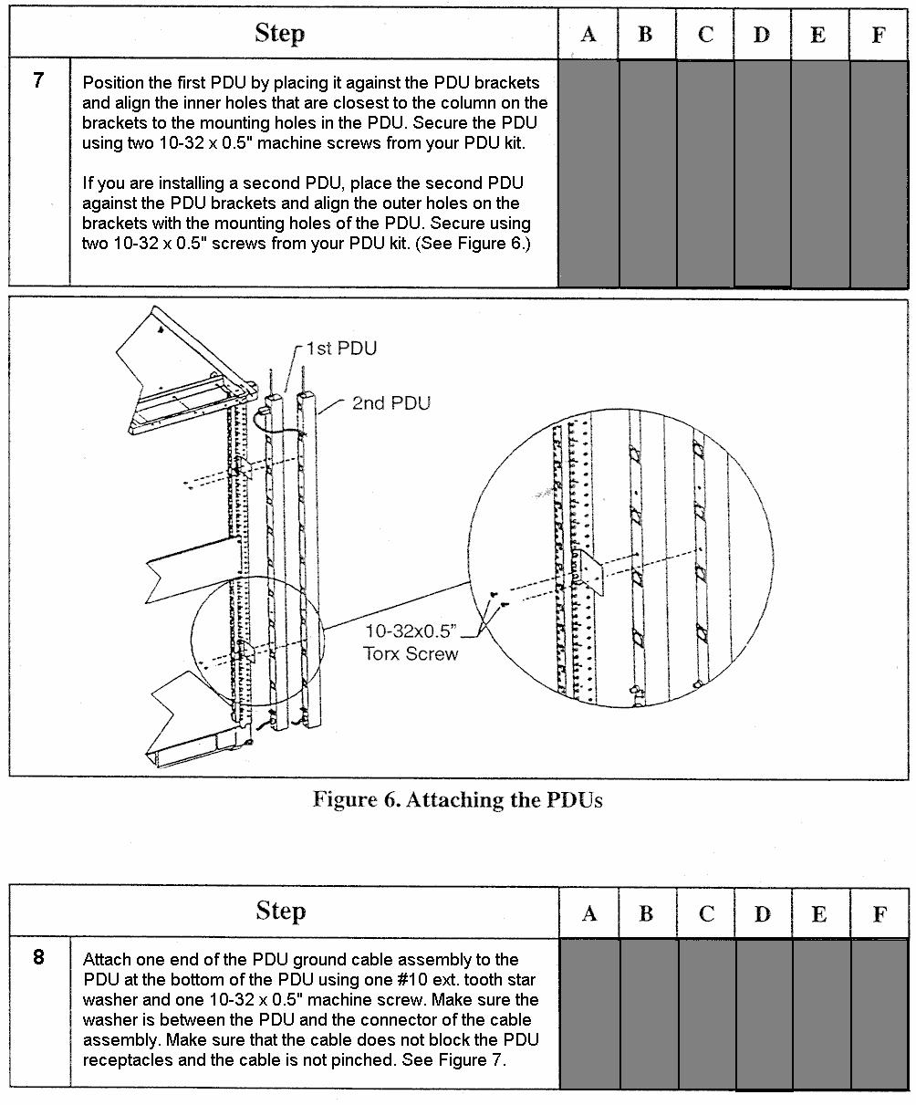
Transcription
1 Agilent Power Distribution Unit (PDU) Installation Guide For use with Agilent PDU kits and PDU installation kits for Agilent instrument racks June 2008 Edition 7 E0608 * *
2 Notice The information contained in this document is subject to change without notice. AGILENT TECHNOLOGIES MAKES NO WARRANTY OF ANY KIND WITH REGARD TO THIS MATERIAL, INCLUDING, BUT NOT LIMITED TO, THE IMPLIED WARRANTIES OF MERCHANTABILITY AND FITNESS FOR A PARTICULAR PURPOSE. Agilent Technologies shall not be liable for errors contained herein or for incidental or consequential damages in connection with the furnishing, performance, or use of this material. This document contains proprietary information, which is protected by copyright. All rights are reserved. No part of this document may be photocopied, reproduced, or translated into another language without the prior written consent of Agilent Technologies. Copyright , 1995, 2001, 2007, 2008 AGILENT TECHNOLOGIES, Inc. Agilent Technologies, Inc Stevens Creek Blvd. Santa Clara, CA USA
3 Safety and Regulatory Information For your protection, this product has been tested for conformance to various national and international regulations and standards. The scope of this regulatory testing includes electrical and mechanical safety, electromagnetic emissions, immunity, ESD, acoustics, and hazardous materials. Where required, certifications are obtained from third party test agencies. Certification marks appear on the product label. In addition, various regulatory bodies require information under the headings below. Please refer to the Safety Information guide provided with the Power Distribution Unit (PDU) for additional important information. This product and related documentation must be reviewed for familiarization with safety markings and instructions before operation. WARNING The WARNING sign denotes a hazard. It calls attention to a procedure, practice, or situation which, if not done correctly or adhered to, could result in injury. Do not proceed beyond a WARNING sign until the indicated conditions are fully understood and met. CAUTION The CAUTION sign denotes a hazard. It calls attention to an operating procedure, practice, or situation which, if not done correctly or adhered to, could damage or destroy part or the entire product. Do not proceed beyond a CAUTION sign until the indicated conditions are fully understood and met. Safety Warnings The following warnings and cautions are applicable to all Agilent PDUs. Please observe all safety precautions and warnings. This product has not been evaluated for connection to an IT power system, an AC distribution system having no direct connection to earth (ground), according to EN Grounding WARNING This is a safety class I product and has a protective earthing (grounding) terminal. There must be an uninterruptible safety earth ground from the main power source to the product's input wiring terminals, power cord, or supplied cord set. Whenever it is likely that the protection has been impaired, disconnect the power cord until the ground has been restored. Leakage Current WARNING Due to types of products that can be connected to the PDU, there is a risk of high leakage current (3.5 ma). Reliable ground circuit continuity is vital for safe operation of this product. To reduce the risk of electric shock, earth (ground) connection is essential before connecting the power supply. Never operate the PDU with the ground conductor disconnected. 3
4 No Replaceable Parts WARNING Do not attempt to open or repair the Power Distribution Unit (PDU). There are no replaceable parts inside the PDU. If the power cord or switch cord is frayed, cut, or damaged, replace the entire PDU. Power Limitations CAUTION To reduce the risk of overload, do not load any single PDU with more than a maximum of 16 Amperes. In addition, do not load a single NEMA 5-15 or IEC-320 receptacle with more than 15 Amperes. Intended Use of Equipment The Agilent Power Distribution Units (PDU) described in this manual are intended to be installed and used in the Agilent E3661B, E3662B, and E7590A Instrument Racks in accordance with the procedures in this manual. NOTE The Agilent PDUs are designed to be installed in the current Agilent E3661B, E3662B, and E7690A products, as well as previous versions of the Agilent EIA 19-inch Instrument Rack System products. For information about rack accessories compatibility, see the Web page and Agilent Enclosures Solutions Product Catalog at or contact your Agilent Sales Representative. Cleaning Disconnect the power from the PDU before cleaning. Use only a damp cloth to clean the surfaces of the PDU. 4
5 General Information The Agilent E7685A PDU Installation Kit enables you to mount an Agilent Power Distribution Unit (PDU) in an Agilent instrument rack. This kit is required if the rack is not already equipped with a PDU, or if you want to install a switched PDU in a rack containing an unswitched PDU. Each PDU installation kit allows the installation of up to two PDU kits. Instrument racks are designed to house two PDU kits only. The voltage of a second PDU must match that of the installed PDU for correct operation of the illuminated switch. To support worldwide power requirements, four Agilent PDU kits are available. The Agilent E7685A PDU Installation Kit allows the installation of any of the following PDU kits: Kit Number Description E PDU - 1.3m, North America ( V) (NEMA receptacles) E PDU - 1.3m, International ( V) (IEC receptacles) E PDU - 1.6m/2.0m, North America ( V) (NEMA receptacles) E PDU - 1.6m/2.0m, International ( V) (IEC receptacles) The above-listed PDU kits are intended to be used only in the following Agilent rack enclosures: E3661B, E3662B, and E7590A. E7685A PDU Installation Kit Contents The Agilent E7685A PDU Installation Kit contains the following: Item Quantity Description Part Number 1 1 Forehead Assembly - with switch cutout PDU Support Bracket C Sheet Metal Nuts (10-32) Machine Screw, Torx T x0.5inch NOTE The installation of a first PDU requires the purchase of the Agilent E7685A PDU Installation Kit. This kit provides hardware and rack components required to complete the installation. The installation of a second PDU does not require an additional kit. However, you will need the kit s switch and hardware if the first PDU was not switched, and you are adding a switched PDU. The voltage of a second PDU must match that of the installed PDU for correct operation of the illuminated switch. When the remote switch is not utilized, the plug is considered to be the disconnect device. When the plug is the disconnect device the socket-outlet shall be installed near the equipment and shall be readily accessible. 5
6 Tools Required To install the PDU kit, you will need the following tools: T25 Torx driver. Wrench or nut driver to fit 3/8 inch hex nut. PDU Kit Contents The four Agilent PDU kits contain the following: PDU Kit Number 1.3m Kit: E E Item Number Quantity Description 1 1 PDU 1.3m PDU: V North American (NEMA receptacles) V International (IEC receptacles) 1.6m Kit: E E m PDU: V North American (NEMA receptacles) V International (IEC receptacles) All 2 3 Machine Screw, Torx T25, 10-32x0.5 inch (p/n ) All 3 2 Washer-external tooth, #10 (p/n ) All 4 1 Nut-Hex w/ext. tooth lock washer, (p/n ) All 5 1 Cable assembly, ground (p/n C ) 6
7 PDU Specifications The specifications for the customer orderable PDUs are given in the following table: Model Number E E E E Input V, 50/60 Hz V, 50/60 Hz V, 50/60 Hz V, 50/60 Hz Output V, 50/60 Hz, 16A V, 50/60 Hz, 16A V, 50/60 Hz, 16A V, 50/60 Hz, 16A 1-IEC 320 C13 Receptacle 5-NEMA 5-15R Receptacles 6-IEC 320 C13 Receptacles 1-IEC 320 C13 Receptacle 9-NEMA 5-15R Receptacles 1-IEC 320 C19 Receptacle 10-IEC 320 C13 Receptacles Operating Temperature 0 C to 55 C 0 C to 55 C 0 C to 55 C 0 C to 55 C Operating Humidity 5% to 80% RH, non-condensing 5% to 80% RH, non-condensing 5% to 80% RH, non-condensing 5% to 80% RH, non-condensing Operating Environment Indoor Location Indoor Location Indoor Location Indoor Location NOTE V, 50/60 Hz PDUs (E and E ) are supplied with a power cord terminated with a NEMA 5-20P plug to fit a 20A receptacle V, 50/60 Hz PDUs (E and E ) are supplied without a power plug the PDU power cord is un-terminated. The installer must install the correct plug for the country of installation. All PDUs ( V or V) must be connected to a dedicated 20A circuit. The following table gives the specifications for the E PDU. This PDU is not customer orderable and is used in Agilent-integrated systems only. Customers should order part number E instead. Model Number E Input Output Operating Temperature Operating Humidity Operating Environment V, 50/60 Hz V, 50/60 Hz, 16A 1-IEC 320 C19 Receptacle 10-IEC 320 C13 Receptacles 0 C to 55 C 5% to 80% RH, non-condensing Indoor Location 7
8 Note: When the remote switch is not utilized, the plug is considered to be the disconnect device. When the plug is the disconnect device the socket-outlet shall be installed near the equipment and shall be readily accessible. 8
9 9
10 10
11 11
12 12
13 13
14 14
15 15
16 Forehead Bezel, (supplied as part of E7685A PDU Installation Kit) WHITE WIRE (PIN 3A) I TOP O 5B 1A BLACK WIRE (PIN 5B) 4B RED WIRE (PIN 4B) GREEN LED THIS SIDE 3A 2A PDU Switch Cable Harness Cable Clip Note: When the remote switch is not utilized, the plug is considered to be the disconnect device. When the plug is the disconnect device the socket-outlet shall be installed near the equipment and shall be readily accessible. Figure 8. Configuring the Forehead Assembly 16
 position. This completes the installation of the Power Distribution Unit (PDU). Place this Guide with your rack documentation.")
17 Figure 9. Main Power Switch Connection (new-style switch)* Verify that the PDU is functioning correctly. The LED lamp on the rocker switch should light up when the switch is in the On (1) position. The lamp should remain unlit when the switch is in the Off (0) position. This completes the installation of the Power Distribution Unit (PDU). Place this Guide with your rack documentation. * The power switch supplied is black, and has five terminals. If you have an older installation with a white, six terminal switch, see Connecting the Old Style Switch on page
18 Connecting the Old Style Switch The PDU Installation Kit and current-production instrument racks contain a black switch with five terminals on the back. This switch has a green LED indicator that should appear on the left when the switch is installed (see figure 8). However, if you are installing a new PDU in an older rack installation, it may have the older, white switch with six terminals on the back. This switch has the indicator light on the right side when installed. If your system has this older, white six-terminal switch, the correct wiring connections are as shown in figure 10 below. Figure 10. Main Power Switch Connection (old-style switch) Note: If you replace the old six-terminal switch in your rack installation with the new five-terminal switch provided in the PDU Installation Kit, you must of course wire the PDU(s) as shown in figure 9. 18
Agilent N2739A 1000 Series Oscilloscope Rack Mount Kit
 Agilent N2739A 1000 Series Oscilloscope Rack Mount Kit Installation Guide Agilent Technologies Notices Agilent Technologies, Inc. 2008 No part of this manual may be reproduced in any form or by any means
Agilent Technologies E5385A 100-Pin Probe
 Agilent Technologies E5385A 100-Pin Probe Installation Note The Agilent Technologies E5385A 100-pin probe provides a convenient way to connect two Agilent Technologies logic analyzer probe cables to a
Agilent Technologies E5346A 38-Pin Probe and E5351A 38-Pin Adapter Cable
 Agilent Technologies E5346A 38-Pin Probe and E5351A 38-Pin Adapter Cable Installation Note The 38-pin probe and adapter cable provide a convenient way to connect two Agilent Technologies logic analyzer
Agilent N2916B 6000 and 5000 Series Oscilloscope Rack Mount Kit
 Agilent N2916B 6000 and 5000 Series Oscilloscope Rack Mount Kit Installation Guide Agilent Technologies Notices Agilent Technologies, Inc. 2005, 2007 No part of this manual may be reproduced in any form
Firmware Guide. Keysight PXIe Chassis Family
 Firmware Guide Keysight PXIe Chassis Family Notices Keysight Technologies, Inc. 2018 No part of this manual may be reproduced in any form or by any means (including electronic storage and retrieval or
Agilent OBSAI Protocol Tester
 Agilent OBSAI Protocol Tester Hardware Reference Guide Agilent Technologies Notices Agilent Technologies, Inc. 2008 No part of this manual may be reproduced in any form or by any means (including electronic
87421/22A Power Supply. Operating and Service Manual
 87421/22A Power Supply Operating and Service Manual Agilent Part Number: 87421-90001 Printed in USA April 2001 Supersedes: September 1998 Notice The information contained in this document is subject to
Agilent 70612B K18 Switch Matrix
 Agilent 70612B K18 Switch Matrix Hardware Reference Manual Agilent Technologies COPYRIGHT 2000 AGILENT TECHNOLOGIES, INC. ALL RIGHTS RESERVED. NO PART OF THIS DOCUMENT MAY BE REPRODUCED IN ANY FORM OR
G5 PDU Installation Guide
 G5 PDU Installation Guide 1 Contents Before You Begin... 3 Overview... 3 Important Safety Information... 3 Required Tools... 5 Section 1 Introduction... 6 Classification Overview... 6 Features... 7 Form
Agilent U2941A Parametric Test Fixture
 Agilent U2941A Parametric Test Fixture Operating Guide Agilent Technologies Notices Agilent Technologies, Inc. 2008 No part of this manual may be reproduced in any form or by any means (including electronic
HP UPS R/T3000 G2. Overview. Precautions. Kit contents. Installation Instructions
 HP UPS R/T3000 G2 Installation Instructions Overview The HP UPS R/T3000 G2 features a 2U rack-mount with convertible tower design and offers power protection for loads up to a maximum of 3300 VA/3000 W
HP UPS R/T3000 ERM. Overview. Precautions. Installation Instructions
 HP UPS R/T3000 ERM Installation Instructions Overview The ERM consists of two battery packs in a 2U chassis. The ERM connects directly to a UPS R/T3000 or to another ERM. Up to two ERM units can be connected.
Agilent Technologies E5339A 38-Pin Low-Voltage Probe
 Agilent Technologies E5339A 38-Pin Low-Voltage Probe Installation Note The 38-pin low-voltage probe provides a convenient way to connect two Agilent Technologies logic analyzer probe cables to a small
Model 2460-KIT. Screw Terminal Connector Kit. Description / September 2014 *P * 1
 Keithley Instruments 28775 Aurora Road Cleveland, Ohio 44139 1-800-935-5595 http://www.keithley.com Model 2460-KIT Screw Terminal Connector Kit Description The Model 2460-KIT Screw Terminal Connector Kit
Installation Note. Removable Hard Disk Drive Upgrade Kit. For All PNA Series RF Network Analyzers. Network Analyzer Model Number
 Installation Note Removable Hard Disk Drive Upgrade Kit For All PNA Series RF Network Analyzers Network Analyzer Model Number E8356A, E8357A, E8358A E8801A, E8802A, E8803A N3381A, N3382A, N3383A Upgrade
RZ2 BioAmp Processor. Operator s Manual
 RZ2 BioAmp Processor Operator s Manual RZ2 BioAmp Processor Operator s Manual Copyright 2008-2013 Tucker-Davis Technologies, Inc. (TDT). All rights reserved. No part of this manual may be reproduced or
Agilent 85130C NMD 3.5 mm to Type-N Adapter Kit
 Agilent 85130C NMD 3.5 mm to Type-N Adapter Kit Operating and Service Manual Agilent Technologies Notices Agilent Technologies, Inc. 1987, 2004, 2008 No part of this manual may be reproduced in any form
Agilent E4418/19A Power Meter Hardware Upgrade Kit
 Agilent E4418/19A Power Meter Hardware Upgrade Kit (E9300 Compatible) Installation Guide Agilent Technologies Notices Agilent Technologies, Inc. 2009 No part of this manual may be reproduced in any form
Keysight E5864A Removable Hard Drive for Series Logic Analyzers. Installation Guide
 Keysight E5864A Removable Hard Drive for 16850-Series Logic Analyzers Installation Guide Notices Keysight Technologies 2013-2014 No part of this manual may be reproduced in any form or by any means (including
The power behind competitiveness. Delta Infrasuite Power Management. Power Distribution Unit. User Manual.
 The power behind competitiveness Delta Infrasuite Power Management Power Distribution Unit User Manual www.deltapowersolutions.com Save This Manual This manual contains important instructions and warnings
RZ5/RZ5D/RZ6 Processor. Operator s Manual
 RZ5/RZ5D/RZ6 Processor Operator s Manual RZ5/RZ5D/RZ6 Processor Operator s Manual Copyright 2010-2013 Tucker-Davis Technologies, Inc. (TDT). All rights reserved. No part of this manual may be reproduced
Agilent 34826A BenchLink Data Logger for 34980A. Getting Started Guide. Agilent Technologies
 Agilent 34826A BenchLink Data Logger for 34980A Getting Started Guide Agilent Technologies Notices Agilent Technologies, Inc. 2006 No part of this manual may be reproduced in any form or by any means (including
Keysight Add Source and Receiver Attenuators Upgrade Kit
 Keysight Add Source and Receiver Attenuators Upgrade Kit To Upgrade PNA N5221A or N5222A Option 401 to Option 417 Upgrade Kit Order Numbers: N5221AU-417 or N5222AU-417 Keysight Kit Number: N5222-60107
Keysight Second Source, Combiner, and Mechanical Switches Upgrade Kit
 Keysight Second Source, Combiner, and Mechanical Switches Upgrade Kit To Upgrade PNA-X N5241A, N5242A, or N5249A Option 419 to Option 423 Upgrade Kit Order Number: N5241AU- 927, N5242AU- 927, and N5249AU-
HP R/T2200 UPS. Overview. Precautions. Installation Instructions. The HP UPS R/T2200 features power protection for loads up to 2200 VA/1600 W.
 HP R/T2200 UPS Installation Instructions Overview The HP UPS R/T2200 features power protection for loads up to 2200 VA/1600 W. For more information about any of the topics covered in this document, see
Installation Note. Source Attenuators and Bias Tees Upgrade Kit. For E8362B/C PNA Series Microwave Network Analyzers. Network Analyzer Model Number
 Installation Note Source Attenuators and Bias Tees Upgrade Kit For E8362B/C PNA Series Microwave Network Analyzers Network Analyzer Model Number Upgrade Kit Part Number E8362B/C E8362-60115 Agilent Part
Installation RA5112-C-16A-C20. Basic Rack Power Distribution Unit
 Installation RA5112-C-16A-C20 Basic Rack Power Distribution Unit Contents Before You Begin........................1 Safety and grounding information..........1 How to Install the Rack PDU...............2
E1135C PDU and Pod Upgrade Procedure
 E4030-90010 Rev. B 12/2003 In this Document... Tools Needed, 2 Contents of the Upgrade Kits, 2 Installation Procedures, 4 Verifying the Power Option of the New PDU, 4 Removing the PDU from the Support
Errata. Agilent References in this manual. About this manual. Support for your product
 Errata Agilent References in this manual NOTICE: This document contains references to Agilent Technologies. Agilent s former Test and Measurement business has become Keysight Technologies. For more information,
Agilent Protocol Analyzer and Jammer for USB. Quick Start Guide
 Agilent Protocol Analyzer and Jammer for USB Quick Start Guide Notices Agilent Technologies, Inc. 2011 No part of this manual may be reproduced in any form or by any means (including electronic storage
Panduit Basic Rack PDU
 Panduit Basic Rack PDU User Manual Release 1.0 Issue 1.0 Copyright 2014 Panduit Corp. All rights reserved. No part of this book shall be reproduced, stored in a retrieval system, or transmitted by any
Keysight 11878A 50 Ohm 3.5 mm Adapter Kit
 Keysight 11878A 50 Ohm 3.5 mm Adapter Kit Operating and Service Manual Notices Keysight Technologies 1989, 2004, 2013, 2014 No part of this manual may be reproduced in any form or by any means (including
This 4200-RM Rack Mount Kit is for installation in 4200-CAB series cabinets only.
 Keithley Instruments, Inc. 28775 Aurora Road Cleveland, Ohio 44139 (440) 248-0400 Fax: (440) 248-6168 www.keithley.com Model 4200-RM Rack Mount Kit Packing List Introduction NOTE This 4200-RM Rack Mount
Keysight Second Source, Combiner, and Mechanical Switches Upgrade Kit
 Keysight Second Source, Combiner, and Mechanical Switches Upgrade Kit To Upgrade PNA-X N5241A or N5242A Option 219 to Option 224 For Analyzers with Serial Numbers Prefixed MY/SG/ US5201 and Above Upgrade
±15 V Current-Limited Power Supply
 USER S GUIDE ±15 V Current-Limited Power Supply Model 0901 Newport Corporation 3635 Peterson Way Santa Clara, CA 95054 www.newport.com/newfocus EU Declaration of Conformity We declare that the accompanying
RM3100 Rackmount Kit for the AFG3000 and AFG3000C Series Arbitrary Function Generators
 xx RM3100 Rackmount Kit for the AFG3000 and AFG3000C Series Arbitrary Function Generators ZZZ Instructions Register now! Click the following link to protect your product. www.tektronix.com/register www.tektronix.com
2260B-RMK-Series Rack Mount Kit
 Keithley Instruments, Inc. 28775 Aurora Road Cleveland, Ohio 44139 1-888-KEITHLEY http://www.keithley.com Assembly and Mounting Instructions Introduction The 2260B-RMK-Series Rack Mount Kit is suited for
Quick Start/Installation Guide
 Agilent Technologies E5850A Time Correlation Fixture Quick Start/Installation Guide The Agilent E5850A time correlation fixture allows you to make time-correlated measurements between a 1680/90 or 16700
Panduit Basic Rack PDU with Local Meter
 Panduit Basic Rack PDU with Local Meter User Manual Release 1.0 Issue 1.0 Copyright 2014 Panduit Corp. All rights reserved. No part of this book shall be reproduced, stored in a retrieval system, or transmitted
Keysight 11636B APC-3.5 mm Power Divider DC to 26.5 GHz
 Keysight 11636B APC-3.5 mm Power Divider DC to 26.5 GHz Operating and Service Manual Notices Keysight Technologies 1985, 2013, 2014 No part of this manual may be reproduced in any form or by any means
Model 2380 Rack-Mount Kit
 Keithley Instruments 28775 Aurora Road Cleveland, Ohio 44139 1-800-935-5595 http://www.tek.com/keithley Model 2380 Rack-Mount Kit Installation Instructions Introduction The Model 2380 Fixed Rack-Mount
Agilent InfiniiMax II 1168A/1169A Probes
 Agilent InfiniiMax II 1168A/1169A Probes Handling Guide Agilent Technologies Notices Agilent Technologies, Inc. 2008 No part of this manual may be reproduced in any form or by any means (including electronic
DS-1H05 Ethernet-over-Coax Extender. User Manual
 DS-1H05 Ethernet-over-Coax Extender User Manual Thank you for purchasing our product. If there is any question or request, please do not hesitate to contact dealer. This manual is applicable to DS-1H05-T,
hp uninterruptible power system r12000 xr models installation instructions
 hp uninterruptible power system r000 xr models installation instructions Overview These instructions show how to install an uninterruptible power system (UPS). For detailed information about the UPS, refer
Model 8020-KHV. Kelvin Keithley Triaxial Connector Card. Description / October 2014 *P * 1
 Keithley Instruments 28775 Aurora Road Cleveland, Ohio 44139 1-800-935-5595 http://www.keithley.com Model 8020-KHV Kelvin Keithley Triaxial Connector Card Description The Model 8020-KHV Keithley HV Connector
Agilent N4219B Packet Analysis Probe for Serial ATA. User s Guide
 Agilent N4219B Packet Analysis Probe for Serial ATA User s Guide A Notices Agilent Technologies, Inc. 2002-2005 No part of this manual may be reproduced in any form or by any means (including electronic
Agilent CSV Export Utility
 Agilent CSV Export Utility User Guide Agilent Technologies Notices Agilent Technologies, Inc. 2011 No part of this manual may be reproduced in any form or by any means (including electronic storage and
Adapter Kit for PanelView 1200/1200e Touch Screen Terminal Cutout
 Installation Instructions Adapter Kit for PanelView 1200/1200e Touch Screen Terminal Cutout Catalog Numbers 2711-NR5T, 2711P-RAT12E2 Topic Page About This Publication 1 Important User Information 2 About
VFI RTG PDU 6-10K. Installation and user manual. Service and support: Call your local service representative
 VFI RTG PDU 6-10K Installation and user manual Service and support: Call your local service representative SAFETY INSTRUCTIONS SAVE THESE INSTRUCTIONS. This manual contains important instructions that
BenchCel Workstations Software
 BenchCel Workstations Software User Guide For Research Use Only. Not for use in diagnostic procedures. Original Instructions Notices Agilent Technologies, Inc. 2017 No part of this manual may be reproduced
Model 2380 Rack-Mount Kit
 Keithley Instruments 28775 Aurora Road Cleveland, Ohio 44139 1-800-935-5595 http://www.tek.com/keithley Model 2380 Rack-Mount Kit Installation Instructions Introduction The Model 2380 Fixed Rack-Mount
Agilent E2943A/E2944A ATCA Probes for Advanced Switching Interconnect
 Agilent E2943A/E2944A ATCA Probes for Advanced Switching Interconnect Hardware Setup Guide Agilent Technologies Notices Agilent Technologies, Inc. 2005 No part of this manual may be reproduced in any form
Cisco CRS 3-Phase AC Power Distribution Unit Installation Guide 2. Cisco CRS 3-Phase AC Power Distribution Unit 2
 Cisco CRS 3-Phase AC Power Distribution Unit Installation Guide Cisco CRS 3-Phase AC Power Distribution Unit Installation Guide 2 Cisco CRS 3-Phase AC Power Distribution Unit 2 Revised: November 18, 2016,
Installation and Getting Started Guide. HP ProCurve 600/610 External Power Supplies. PoE. Power over Ethernet Devices
 Installation and Getting Started Guide HP ProCurve 600/610 External Supplies www.hp.com/go/hpprocurve PoE over Ethernet Devices HP ProCurve 600/610 External Supplies Installation and Getting Started Guide
Agilent N1022A Active Probe Adapter User Guide
 Agilent N1022A Active Probe Adapter User Guide Notices Agilent Technologies, Inc. 2003 No part of this manual may be reproduced in any form or by any means (including electronic storage and retrieval or
Agilent 16442B. User s Guide. Agilent Technologies
 Agilent 16442B Test Fixture User s Guide Agilent Technologies Notices Agilent Technologies 2002, 2006 No part of this manual may be reproduced in any form or by any means (including electronic storage
User's Guide. Phase Sequence and Motor Rotation Tester Model
 User's Guide Phase Sequence and Motor Rotation Tester Model 480403 Introduction Congratulations on your purchase of the Extech Model 408403 Motor and Phase Rotation Indicator. This handheld instrument
86100 Series Infiniium DCA Oscilloscope
 86100 Series Infiniium DCA Oscilloscope This manual provides the documentation for the following instruments 86100D 86100C User s Manual Notices Keysight Technologies, Inc. 20xx-2014 No part of this manual
User s Manual Power Supply IM E. 5th Edition
 User s Manual 701934 Power Supply 5th Edition Thank you for purchasing the 701934 Power Supply. This user s manual contains useful information about the functions and operating procedures of the 701934
Agilent E5072A Network Analyzer
 Agilent E5072A Network Analyzer Installation Guide Agilent Technologies Notices Agilent Technologies, Inc. 2011 No part of this manual may be reproduced in any form or by any means (including electronic
Contents. HP E1586A Rack Mount Terminal Panel User s Manual
 Contents HP E1586A Rack Mount Terminal Panel User s Manual Description... 5 Connecting to VXIbus Instruments... 5 Interconnect Cables... 5 Terminal Block Connections... 6 Using the Terminal Panel for Reference
Cary 50. Pre-Installation Manual
 Cary 50 Pre-Installation Manual Notices Agilent Technologies, Inc. 1999, 2006 and 2011 No part of this manual may be reproduced in any form or by any means (including electronic storage and retrieval or
Agilent Gb/s Serial BERT
 Agilent 3.125 Gb/s Serial BERT N5980A Programming Guide Notices Agilent Technologies, Inc. 2007 No part of this manual may be reproduced in any form or by any means (including electronic storage and retrieval
Installation Note. IF Access Upgrade Kit. For PNA Series Microwave Network Analyzers. Network Analyzer Model Number. Upgrade Kit Part Number
 Installation Note IF Access Upgrade Kit For PNA Series Microwave Network Analyzers Network Analyzer Model Number E8361A/C, E8362B/C, E8363B/C, E8364B/C Upgrade Kit Part Number E8362-60116 Agilent Part
MC 11 EB-2 Power supply cabinet with external bus, AC version
 MC 11 EB-2 Power supply cabinet with external bus, AC version USER/MAINTENANCE MANUAL 1 SLOT 0 SLOT 1 SLOT 2 SLOT 3 SLOT 4 SLOT 5 SLOT 6 SLOT 7 SLOT 8 SLOT 9 SLOT 10 SLOT 11 EB-2 (a) MC11 (b) (c) Figures
Installation Note. Agilent Technologies 85105A Option 50 Installation Instructions for RF Switch Replacement Kit
 Installation Note Agilent Technologies 85105A Option 50 Installation Instructions for RF Switch Replacement Kit 85105-60047 Part Number 85105-90023 Printed in USA August 2002 Notice. The information contained
CVU-200-KIT. 200 V Bias Tee Kit. Description. Parts list / October 2014 *P A* 1
 Keithley Instruments 28775 Aurora Road Cleveland, Ohio 44139 1-800-935-5595 http://www.keithley.com CVU-200-KIT 200 V Bias Tee Kit Description The CVU-200-KIT Bias Tee Kit consists of three 2600-RBT-200
PanelView Plus/VersaView CE Terminals and Display Modules
 Installation Instructions PanelView Plus/VersaView CE Terminals and Display Modules (Catalog Numbers 2711P-xxxxxx, 6182H-xxxxxx) English Inside: Overview...2 For More Information...2 Modular Components...3
BIT-3000 Dynamic Sequencing Generator and Analyzer. Datasheet 1.11
 BIT-3000 Dynamic Sequencing Generator and Analyzer Datasheet 1.11 BitifEye Digital Test Solutions GmbH Herrenberger Strasse 130 71034 Boeblingen, Germany info@bitifeye.com www.bitifeye.com Notices BitifEye
B63/ NS MS. EtherNet/IP LINK
 3 609 929 B63/ IMenip 2008-09 NS MS EtherNet/IP LINK 3 609 929 B63/2008-09 IMenip Bosch Rexroth AG 15/76 Table of Contents About this document................. 16 General safety instructions............
HypotULTRA. Quick Start Guide SAFETY CHECKLIST. Survey the test station. Make sure it is safe & orderly.
 EN 61010-1 EN 61010-31 Quick Start Guide HypotULTRA for the following models: 7800, 7820, 7850 SAFETY CHECKLIST Survey the test station. Make sure it is safe & orderly. Always keep unqualified/unauthorized
Agilent G6011A Quiet Cover MS
 Agilent G6011A Quiet Cover MS Service Manual Agilent Technologies Notices Agilent Technologies, Inc. 2013 No part of this manual may be reproduced in any form or by any means (including electronic storage
Extended Frequency Range Upgrade Kit (50 GHz to 67 GHz)
") Installation Note Extended Frequency Range Upgrade Kit (50 GHz to 67 GHz) Upgrade Kit Number: E8364-60105 For E8364B/C Microwave Network Analyzers WITHOUT the Configurable Test Set Option (Option 014)
Installation Note Extended Frequency Range Upgrade Kit (50 GHz to 67 GHz) Upgrade Kit Number: E8364-60105 For E8364B/C Microwave Network Analyzers WITHOUT the Configurable Test Set Option (Option 014)
CVU-3K-KIT. 3 kv Bias Tee Kit. Description. Parts list / October 2014 *P * 1
 Keithley Instruments 28775 Aurora Road Cleveland, Ohio 44139 1-800-935-5595 http://www.keithley.com CVU-3K-KIT 3 kv Bias Tee Kit Description The CVU-3K-KIT Bias Tee Kit consists of three bias tees for
MODEL 805 USER MANUAL
 MODEL 805 USER MANUAL All Rights Reserved Page 1 of 12 UNPACKING & INSPECTION Save all packing materials they are required for returns and warranty service. Inspect the 805 and packing materials for any
SmartZone Gateway- Enabled M Series Rack PDU
 SmartZone Gateway- Enabled M Series Rack PDU User Manual Release 1.0 Issue 1.0 Copyright 2014 Panduit Corp. All rights reserved. No part of this book shall be reproduced, stored in a retrieval system,
Wall-Mounting your HP TouchSmart. User Guide
 Wall-Mounting your HP TouchSmart User Guide The only warranties for Hewlett-Packard products and services are set forth in the express statements accompanying such products and services. Nothing herein
Avanti HP Series Centrifuges Preinstallation
 J3HP-TB-001AC May 2009 Avanti HP Series Centrifuges Preinstallation INTRODUCTION Purchase of an Avanti HP series high performance centrifuge includes installation and Basic Instrument Training for two
HV-CS kv Edge Mount Triaxial Jack
 Keithley Instruments 28775 Aurora Road Cleveland, Ohio 44139 1-800-935-5595 http://www.tek.com/keithley HV-CS-1589 3 kv Edge Mount Triaxial Jack Installation Information Description The Keithley Instruments
Model 8020-STC. Kelvin Standard Triaxial Connector Card. Description / October 2014 *P * 1
 Keithley Instruments 28775 Aurora Road Cleveland, Ohio 44139 1-800-935-5595 http://www.keithley.com Model 8020-STC Kelvin Standard Triaxial Connector Card Description The Model 8020-STC Kelvin Standard
A1. Multilin EPM 4600 Meter Displays DIS3500/DIS5700. Quick Start Guide. GE Digital Energy
 GE Digital Energy Multilin EPM 4600 Meter Displays DIS3500/DIS5700 Quick Start Guide Product version: 1.0x GE publication code: 1601-0500-A1 (GEK-119644) 1601-0500-A1 Copyright 2014 GE Multilin Inc. All
User's Guide. Extech AM A AC Analog Clamp Meter
 User's Guide Extech AM300 300A AC Analog Clamp Meter Introduction Congratulations on your purchase of the Extech AM300 Analog Clamp Meter. This device measure AC Voltage and Current, DC Voltage, and Resistance.
iconverter 2-Module Power Chassis
 iconverter 2-Module Power Chassis User Manual 38 Tesla, Irvine, CA 92618 USA Phone: (949) 250-6510; Fax: (949) 250-6514 Page 1 Warning The operating description in this Instruction Manual is for use by
Metered Rack PDU Rack PDU, Metered, Zero U, 5.7kW,208V,(36)C13& (6)C19; 10' Cord
C13& (6)C19; 10' Cord") Metered Rack PDU Rack PDU, Metered, Zero U, 5.7kW,208V,(36)C13& (6)C19; 10' Cord APC Metered Rack PDU, Input: 208V 3PH, Input Connections: NEMA L21-20P, Cord Length: 10 feet ( 3.05 meters ), Output: 208V,
Metered Rack PDU Rack PDU, Metered, Zero U, 5.7kW,208V,(36)C13& (6)C19; 10' Cord APC Metered Rack PDU, Input: 208V 3PH, Input Connections: NEMA L21-20P, Cord Length: 10 feet ( 3.05 meters ), Output: 208V,
Model 2600B-PM V Protection Module with 1 A Clamp. Description / April 2015 *PPA * 1
 Keithley Instruments 28775 Aurora Road Cleveland, Ohio 44139 1-800-935-5595 http://www.keithley.com Model 2600B-PM-1 200 V Protection Module with 1 A Clamp Description The Model 2600B-PM-1 200 V Protection
CrystalView DVI Multi INSTALLATION AND OPERATIONS MANUAL Stancliff Road Phone: (281)
") CrystalView DVI Multi INSTALLATION AND OPERATIONS MANUAL 10707 Stancliff Road Phone: (281) 933-7673 Houston, Texas 77099 WWW.ROSE.COM LIMITED WARRANTY Rose Electronics warrants the CrystalView Multi to
CrystalView DVI Multi INSTALLATION AND OPERATIONS MANUAL 10707 Stancliff Road Phone: (281) 933-7673 Houston, Texas 77099 WWW.ROSE.COM LIMITED WARRANTY Rose Electronics warrants the CrystalView Multi to
Model 7705 Control Module
 www.keithley.com Model 7705 Control Module User s Guide PA-696 Rev. D / October 2006 A G R E A T E R M E A S U R E O F C O N F I D E N C E Safety Precautions The following safety precautions should be
BS 287 DUAL CHANNEL POWER SUPPLY. User Manual. January 2017 V1.0
 BS 287 DUAL CHANNEL POWER SUPPLY User Manual January 2017 V1.0 Table of contents 1.0 SAFETY INSTRUCTIONS... 3 2.0 GENERAL DESCRIPTION PS 289... 4 3.0 MECHANICAL INSTALLATION... 5 4.0 MAINS POWER & SAFETY
Part No. Z , IA Nov OPERATION MANUAL. High Voltage Digitalmeter A
 Part No. Z1-109-920, IA001723 Nov. 2005 OPERATION MANUAL High Voltage Digitalmeter 149-30A Use of Operation Manual Please read through and understand this Operation Manual before operating the product.
TRC-190 User s Manual
 First Edition, November 2008 www.moxa.com/product 2008 Moxa Inc. All rights reserved. Reproduction without permission is prohibited. The software described in this manual is furnished under a license agreement
USER GUIDE. AXIS T8120 Midspan 15 W 1-port ENGLISH
 USER GUIDE AXIS T8120 Midspan 15 W 1-port ENGLISH Legal Considerations Video and audio surveillance can be prohibited by laws that vary from country to country. Check the laws in your local region before
Installation, Testing, and Operating Procedures 30 AMP PORTABLE AND PERMANENT SERIES GFCI SINGLE and MULTIPHASE
 IMPORTANT! Please read all the information on this sheet. SAVE THESE INSTRUCTIONS! NOTICE BEFORE USING READ INSTRUCTIONS COMPLETELY. TO BE INSTALLED BY A QUALIFIED ELECTRICIAN IN ACCORDANCE WITH NATIONAL
Model 2657A-LIM-3 LO Interconnect Module
 Keithley Instruments, Inc. 28775 Aurora Road Cleveland, Ohio 44139 1-888-KEITHLEY http://www.keithley.com Model 2657A-LIM-3 LO Interconnect Module User's Guide Description The Model 2657A-LIM-3 LO Interconnect
Line Impedance Stabilization Network (LISN)
") Model 3816/2 Line Impedance Stabilization Network (LISN) User Manual ETS-Lindgren Inc. reserves the right to make changes to any product described herein in order to improve function, design, or for any
Model 3816/2 Line Impedance Stabilization Network (LISN) User Manual ETS-Lindgren Inc. reserves the right to make changes to any product described herein in order to improve function, design, or for any
TRC-190 User s Manual
 User s Manual Edition 3.2, May 2017 www.moxa.com/product 2017 Moxa Inc. All rights reserved. User s Manual The software described in this manual is furnished under a license agreement and may be used only
LINE VOLTAGE TESTER CT101 USER S MANUAL. Please read this manual carefully and thoroughly before using this product.
 LINE VOLTAGE TESTER USER S MANUAL CT101 Please read this manual carefully and thoroughly before using this product. KEY FEATURES Visual indication of AC or DC voltage Easy to use approved Safe for CAT
Operating Instructions
 Bracken Hill South West Industrial Estate Peterlee Co Durham SR8 2SW ENGLAND Tel: +44(0)191 5863511 www.seaward.co.uk sales@seaward.co.uk service@seaward.co.uk Part Number 344A550 Revision 1 2006 Seaward
Automated Tuner System Power Distribution Hub
 User Guide Automated Tuner System Power Distribution Hub Model MT1020B MT1020-340 (Rev B) 12/11 User Guide Automated Tuner System Power Distribution Hub Model MT1020B 2900 Inland Empire Boulevard Ontario,
Installation and Operations Manual
 Xtensys User Station Installation and Operations Manual XTR-11 / XTR-12 / XTR-14 10707 Stancliff Road Houston, Texas 77099 800-333-9343 www.rose.com LIMITED WARRANTY Rose Electronics warrants Xtensys
User Guide Automatic Transfer Switch (ATS)
") User Guide Automatic Transfer Switch (ATS) V.1.0 Table of Contents 1. Introduction... 2 2. Product Overview... 2 3. Important Safety Warnings... 3 4. Operation Indicators & Status... 3 5. Installation...
User Guide Automatic Transfer Switch (ATS) V.1.0 Table of Contents 1. Introduction... 2 2. Product Overview... 2 3. Important Safety Warnings... 3 4. Operation Indicators & Status... 3 5. Installation...