Middle East Technical University Department of Computer Engineering RECOMMENDER SYSTEM. Software Design Description Document V1.1.
|
|
|
- Antonia Erica Harvey
- 5 years ago
- Views:
Transcription


1 Middle East Technical University Department of Computer Engineering RECOMMENDER SYSTEM Software Design Description Document V1.1 Dcengo Unchained DuyguKabakcı Işınsu Katırcıoğlu Sıla Kaya Mehmet KorayKocakaya November 24, 2013
2 Change History Date Revision Comment Created Context ViewPoint is updated 5.3. Composition ViewPoint is updated Class Design Concern is updated Class Design Elements is updated 5.5. Interaction ViewPoint is updated 5.6. Interface ViewPoint is updated 5.7. State Dynamics ViewPoint is updated 6. Planning is updated 1
3 Contents 1. Overview Scope Purpose Intended Audience References Definitions Conceptual Model for Software Design Descriptions Software Design In Context Software Design Descriptions Within Life Cycle Influences on SDD Preparation Influences on Software Life Cycle Products Design Verification and Design Role in Validation Design Description Information Content Introduction SDD Identification Design Stakeholders and Their Concerns Design Views Design Viewpoints Design Elements Design Overlays Design Rationale Design Languages Design Viewpoints Introduction Context Viewpoint Design Concerns Design Elements Composition Viewpoint Design Concerns Design Elements Logical Viewpoint Design Concerns
4 Data Design Concern Class Design Concern Design Elements Data Design Elements Class Design Elements Interaction ViewPoint Design Concerns Design Elements Interface Viewpoint Design Concerns Design Elements State Dynamics Viewpoint Design Concerns DesignElements Planning Conclusion
5 Preface This document includes the Software Design Description (SDD) of the Recommender System. This document is prepared according to the IEEE Standart for Information Technology Systems Design Software Design Descriptions IEEE Std Main purpose of this documentation is to provide a complete description of all the system design and views of the project. The Recommender System aims to enhance the existing recommendation tools served to music streaming and downloading tools. In this project, the challenge is to overcome about data design, modules and design viewpoints. The target audience, who wants to make use of this system, can find all related design descriptions information in this document. It assists the software developer team, the stakeholders and the end users. The first section of this document includes the conceptual model for SDD. The role and influences of this document are specified. The following sections include design description information content and design viewpoints of the system. Design viewpoints are indicated along with their related diagrams. They, as a whole, provide the details of the system modeling and architectural design concerns. 4
6 1. Overview 1.1. Scope This document gives the design description for the Recommender System. A set of design elements and viewpoints will be presented in order to specify the design and development process of the software product. Each design concern is expressed in the context of one design view and each design view is given with the corresponding design elements. The document provides a clear understanding of the basic structure of the project and how the implementation process will be carried out Purpose The software design document provides the system modeling and architectural design for the Recommender System. The purpose is to give a general description of the design elements, their interactions, the system s components and behaviour prior to the code development phase. This document verifies whether the design issues conform to the requirements of the Recommender System SRS Document. SDD serves as the primary reference for the code development Intended Audience As stated in section 1.2. Purpose of Recommender System SRS Document, the intended audience are project managers, developers, testers and end users. The design document gives detailed explanation of data, architecture (design viewpoints) and procedural design for project managers, developers and testers. The end users can also be guided by system boundaries and services description in this document References [1] IEEE. (2009). IEEE Standard for Information Technology-Systems Design-Software Design Descriptions.IEEE Computer Society. [2] Recommender System Software Specification Requirements (SRS) Document. (2013). [3] StarUML 5.0 User Guide. (2005). Retrieved from 5
7 [4] Neo4j. (2010). Modeling Categories in a Graph Database. Retrieved from 2. Definitions Term API Cypher Eclipse IEEE Neo4j SDD SRS UML Weka Definition Application Programming Interface A graph query language Multi-language integrated development environment Institute of Electrical and Electronics Engineers Open-source graph database implemented in Java Software Design Description Software Requirements Specification Unified Modeling Language A popular suite of machine learning software written in Java, developed at the University of Waikato, New Zealand 3. Conceptual Model for Software Design Descriptions This section includes basic project terms, concepts and context of SDD in which the documentation is prepared. The conceptual model aims to give a better understanding of the project terminology, software life cycle and frameworks that the project resides on Software Design In Context The software product will be designed in an object-oriented and modular fashion. This project will be implemented with Java using Eclipse as IDE. The software product is planned to be a RESTful web service. The portability is an important issue since the system will be integrated to a separate stand-alone web application. But the opportunity of using a web service 6
8 makes the product platform independent. However, the entire project is context dependent. Since the project mainly relies on the user data type, the product can not be integrated to different contexts such as movie data. Big data and performance are two important issues in recommendation field. The project must be able to support large number of end user data. This case contradicts the performance issue most of the time. Therefore, it is needed to prioritise one of these issues. Big data induce the use of graph database which is an important context in terms of designing and storing data. In this project, graph database will be generated by Neo4j. The Cypher language, which is a query language for Neo4j graph database, will be used. In order to implement the recommendation algorithm and mapreduce algorithm, Weka, a machine learning library implemented in Java, is chosen. It works together with Neo4j graph database Software Design Descriptions Within Life Cycle Influences on SDD Preparation The primary influence on software design process is the Recommender System SRS Document. The product perspective, functional and nonfunctional requirements determine the outline of the architectural design. The additional specifications of the stakeholders related to the frameworks or data affect the SDD preparation period Influences on Software Life Cycle Products The agile method is adopted for the software process model and the software product will reach to a final stage after a series of iterations. The first part of the software cycle is to construct a simple recommendation model by using the existing open-source implementations. The next part is to customize the algorithms according to the partial data and collaborative approach. After the first iteration a prototype will be presented to the stakeholders. The iterations and additional/changing requirements of the stakeholders have influence on software life cycle products. After the first demo, the model will be scaled to big data which is the main concern in this project. 7
9 Design Verification and Design Role in Validation Software design description is the primary reference for the verification and validation of whether the software product designed fulfills the specified requirements in Recommender System SRS Document. The requirements for each specific intended use of the software product are modeled in the design view parts of the document. The verification and validation of the design view models are carried out based on this document. SDD influences test plans and test cases in further stages. The testing process will be handled after the code development. 4. Design Description Information Content 4.1. Introduction The SDD is prepared to identify the architectural design of the Recommender System. This document specifies how the Recommender System will be designed and implemented according to some chief design views SDD Identification The system model identified in this document will be used for each product iteration during the development and implementation periods. After the initial iterations, the prototype will be demonstrated on January 27, The software product will be released by the end of May, Tentative date for the date of issue is May 22, Dcengo Unchained team will be responsible for issuing the Recommender System in association with the issuing organization ARGEDOR. All rights of the end product are reserved. Due to the exclusive rights property, only the copyright holders, Dcengo Unchained and ARGEDOR will be free to modify and distribute the product. However, due to the copyright of the user data received from ARGEDOR, user logs and track information can not be distributed. Scope, references, context and summary can be found in section 1. Overview. Glossary and necessary terminology can be found in section 2. Definitions Design Stakeholders and Their Concerns Stakeholders include Dcengo Unchained team developers, R&D developers of ARGEDOR, testers and end users. Stakeholder s main concerns are accuracy and performance for big user data. The end product is expected to enhance the existing systems at least in one of 8
10 these concerns. This project is based on enhancing the accuracy of recommendations. Further requirements are specified in the SRS document of the Recommender System Design Views This Project will be implemented as web service application with simple web service interface. Therefore, stakeholders can integrate to their web application or they can easily use with web service interface. In this document contextual, composition, interface, logical, interaction and state dynamics view will be explained in next sections. Detailed description and diagrams about these views will clarify them. Each view is given with its corresponding viewpoint Design Viewpoints Software design description identifies context, composition, interface, logical, interaction and state dynamics viewpoints. Context viewpoint specifies the system boundaries and actors interacting with the system. Composition viewpoint identifies the system modules, components, frameworks and system repositories. Interface viewpoint explains the interaction between different software interfaces. Logical viewpoint includes the detailed description of data design and class diagrams. Interaction viewpoint gives the sequence of events in the system and the state dynamics viewpoint models the system as a state machine and shows the state transitions and conditions on these transitions Design Elements All the design elements of this software design description are described in the following sections. Design elements, their attributes, relationships and constraints are explained together with the viewpoints which they belong to. 9
11 4.7. Design Overlays The interface viewpoint includes the user interface. This user interface should not be confused with the web application user interface. The UI component in this project references to the interface of the web service. Its main purpose is receiving inputs and displaying results to the external system Design Rationale The project is planned as a web service. This allows the operations to be software independent and makes the product integrable to stand-alone projects. The project is designed to be able to communicate with different frameworks through separate interfaces. The Recommender System is completely a data-oriented system. Thus, the motivation behind the design choices is the size and format of the user data. The format of the data reinforces the use of separate classes for each item in the dataset; user, track, album and artist. Because each of them has its unique attributes and relations. This modular way can be seen in the logical viewpoint. Big data is the challenging part of this project. The algorithm and software frameworks must support big data concept. That is why Neo4j graph database is preferred over other data storing and processing frameworks. Data storage in graphs allows the items (users, tracks, albums or artists) to be represented as nodes and their relationships can be designed as edges between these nodes. In this representation, the similarity between two users or tracks is marked with weights on the edges and this is completely compatible with graph concept. The similarity is found by graph traversal which is a key function in this project. Neo4j comes with a callback based traversal API which allows to specify traversal rules. Since the data size will increase as new logs are received, insertion of new nodes to a graph database is easier in this system mode. Neo4j also supports distributed file systems, therefore the expanding data can be processed in parallel on several different machines. In the component viewpoint, the deployment on several machines can be seen. The overall system architecture is based on the idea that the database component works in association with a machine learning library component. Weka is chosen as the machine learning library. It provides predictive models and evaluates the quality of the chosen model. It can be 10
12 used as a recommendation engine and combined with the Neo4j graph database. These ready-touse implementations speed up the agile process. Therefore, in the interface viewpoint, the system is in connection with these software libraries Design Languages Unified Modeling Language (UML) and ER diagram are used for the design viewpoint specification. 5. Design Viewpoints 5.1. Introduction Design viewpoints determine the conventions for a system including the architectural models, languages and notations. They are used in the realization part of the design descriptions and constraints of the Recommender System. Several design viewpoints are defined in the following subsections. UML is used as the design language Context Viewpoint This section provides the system boundaries and the actor interactions of the Recommender System. The relationship between the external systems and the Recommender system are displayed within the system environment. The roles of actors and stakeholders are illustrated through UML Use Case diagram Design Concerns Our project will evolve in two ways. One of them is developing a web service which stakeholders integrate into their web applications. The other one is making a web service application. This application has a simple user interface for uploading the dataset or getting recommendation. Interagent gets recommendation via using the web service application or integrating the web service into their web application. The latter one means giving recommendations to end users. The Recommender System is planned to be a RESTful web service that generates reliable track recommendations when integrated into an existing music downloading and streaming web applications. The system processes the ready-to-use data including user logs, track and album 11
13 information. User logs give detailed records relating users to the tracks played at certain times. The system is designed to process the user-track logs of ArgedorMüzik web application. The system is provided with this information, therefore there is no direct interaction with ArgedorMüzik application. The user profile, user feedback, music lists, user comments and the music downloading and streaming services are out of the scope of this software product. It works in association with ArgedorMüzik in terms of data flow. However, the process is restricted to combining the user data and suggesting a track to a specific user. The result is displayed by means of the external system. The end product will be a web service and it can be integrated to other related external systems. But the entire work is context dependent.therefore, the software product only renders service for music applications. Moreover, the Recommender System is aiming to make a web service application which includes a simple user interface for getting recommendation even if it is not integrated to a web application. The interagent can upload/update datasets and get recommendation via this simple application. Figure 5.1 illustrates the configuration of the Recommender system among external systems and Figure 5.2 shows the use case diagram for this system. Figure 5.1: System Context Diagram 12

14 Figure 5.2: Use Case Diagram Design Elements One of the major design entities is the group of stakeholders. The Recommender System is a software project conducted in association with ARGEDOR company and Prof. Dr. İsmail HakkıToroslu. The stakeholders are the recommender systems project management team and R&D team of ARGEDOR. Another group of design entities is the actors of the Recommender System which are end users and interagents. The end users of the Recommender System can be anyone who downloads or plays a track through the music downloading and streaming application. The system is not an online user interactive system. Therefore the user gets the output of the system through the interagent application. This is an expected outcome of a web service. However, the user actions are important because their listening, searching and rating activities generate the user logs. The user logs are delivered by ARGEDOR. Apart from the two 13
15 functionalities of users,recommender system gives recommendation to the external systems. The interagent stands for the R&D team of ARGEDOR.They provide and update dataset for the integrated web service. These functionalities can be seen in Figure 5.2. In Figure 5.1, the external system inputs to the Recommender System which outputs back to the external system. The result is then presented to the users Composition Viewpoint This section provides information about Recommender System components and their connections with each other. The correlation between large system and the Recommender System as a web service is also shown within the overall system environment Design Concerns The aim of this viewpoint is providing information to stakeholders and programmers for planning and controlling the system. This kind of subsystem level illustration can be used for assembling components, cost estimation and schedules in terms of development effort. System components such as libraries, packages, files and their interconnections are illustrated in UML Component diagram. Recommender System is integrated to larger web based music application as a web service. Larger system is a music streaming and downloading application which collects and provides user logs to recommender web service and its graph database. Graph Traversal Algorithms are used for searching through graph database by Recommender component. Machine learning algorithms component uses Weka library which is a part of recommendation generation. After getting recommendation from web service's Recommender component, recommendations can be shown via the user interface of web service. After the integration of music web application and Recommender System, recommendations can also be shown via larger system s user interface. Users can use downloading and streaming music application via PC which can be compatible with Windows/Unix operating systems. Server interacts with REST API of web service which connects to computer cluster. Our recommender web service deals with big data but the earlier prototype do not use big data. Therefore, only single master device is enough for communicating with the database. Figure 5.3 illustrates the subcomponents of the Recommender 14

16 System and interconnections between components. Figure 5.4 and 5.5 shows the hardwarecomponents used to deploy software components for this system. Figure 5.3: System Component and Package Diagram 15


17 Figure 5.4: System Deployment Diagram Figure 5.5: Distributed Systems Deployment Diagram 16
18 Design Elements Web application Functional attribute: Web application provides users with music downloading and streaming. Moreover, it generates data that is used by the web service. Web Application already exists. So, application functions are not our concern except the data flow to our recommender web service. Subordinates attribute: Web application is composed of Music application and data generator. Music application allows users to listen and download tracks. Data generator provides user logs (comes from music application) to Recommender System. Web Service Functional attribute: Web service is used to serve requested recommendation by web application. It communicates the external world such as UI component or web application module. Subordinates attribute: Web service is composed of evaluator and recommender component. Recommender component traverses data via graph traversal algorithms to make recommendations using machine learning algorithms. Evaluator checks the quality of recommendations in offline mode. Evaluator uses approximately 10% of data set as the test cases to control whether a recommendation is suitable or not. Algorithms Functional attribute: This component is used by recommender for traversing data and applying machine learning recommendation algorithms. Subordinates attribute: Algorithms package is composed of graph traversal algorithms component and machine learning algorithms component. Graph traversal algorithms make transactions on Neo4j graph database via Neo4j api. Machine learning algorithms help recommender to generate recommendations. The implementations of the algorithms comes from Weka library. Database Functional attribute: Neo4j graph database stores data about user transactions on tracks. Subordinates attribute: Neo4j api connects database to other components. UI Functional attribute: User interface of recommender web service controls and displays recommendations coming from web service. 17
19 Subordinates attribute: UI is composed of view and controller components. Controller checks whether recommendations exist or not. View component displays recommendations Logical Viewpoint Design Concerns Data Design Concern Recommender System is a highly data dependable system. The size and the organization of the data designate the project stages. Figure 5.6 illustrates the ER diagram of the data entities, relationships and their attributes. It should be noted that the data entities are not organized according to the relational data model. However, Neo4j graph database community declares that they use the same ER diagram notation as in the case of relational database models. The entities, relationships and their attributes conform to the content of the dataset delivered by ARGEDOR. Song, album, performer and user are the data entities whose unique attributes are provided with the dataset. The necessary correlations connecting a song to an album and a performer are also included in the ARGEDOR dataset. There are also user logs that match users to the songs, their performers and albums along with additional information on the listening action. 18
20 Figure 5.6: ER Diagram Class Design Concern This section provides the organization of system classes. They are designed according to the previous section which covers the data organization. System classes also include some specific classes governing database actions and similarity detection methods. They, as a whole, operate to return an accurate recommendation instance to the external system. It should be noted that class design concerns the implementation and development part of the project. During the code development, there can be changes in the class design. They will be provided as an update. 19

21 Figure 5.7: Class Diagram Design Elements Data Design Elements ER diagram in Figure 5.6 shows that there are four data entities; song, performer, album and user. Song entity represents the tracks that can be either played or downloaded through the music downloading and streaming application. This entity has the following attributes: ID: This attribute gives the unique identifier of a song. It is the indexing attribute (the primary key in relational models) of the song entity. PROVIDERID: It is the id of the provider of the song. GENREID: It is the identifier of the group or type of the song. CREATETIME: This attribute specifies the time that the song instance is created. ORIGIN: It states whether the song instance is a Turkish song or not. NAME: It is the name of the song. 20
22 ALLOWEDWEBSTREAM: It indicates whether the song can be played instantly through the web application. ALLOWEDWEBDOWNLOAD: It indicates whether the song can be downloaded. ALLOWEDWEBVIDEOSTREAM: It indicates whether the video of the song can be played instantly before the entire file is transmitted. ALLOWEDMOBILESTREAM: It indicates whether the song can be played instantly through the mobile application. ALLOWEDWAPSTREAM: It indicates whether the song can be played instantly via mobile wireless network. Performer entity represents the author of songs. It has the following attributes: ID: This attribute gives the unique identifier of a performer. It is the indexing attribute (the primary key in relational models) of the performer entity. PROVIDERID: It is the id of the provider of the performer information. NAME: It is the name of the performer. Album entity represents the collection of songs and it has the following attributes: ID: This attribute gives the unique identifier of an album. It is the indexing attribute (the primary key in relational models) of the album entity. PROVIDERID: It is the id of the provider of the album information. CREATETIME: This attribute specifies the time that the album instance is created. ALBUMNAME: It is the name of the album. User entity represents the end users who make use of the music downloading and streaming application. It has the following attribute: ID: This attribute gives the unique identifier of a user. It is the indexing attribute (the primary key in relational models) of the user entity. Map relationship matches the songs to their corresponding performers and albums. In this relation, each song instance must appear once and only once while the performer and album instances can appear at least one time. 21
23 Listen relationship matches the users to the songs played or downloaded. Although the mapping of performer and album information is redundant in this case, the delivered dataset includes this mapping as well. This relationship has three attributes: TIMEOFACTION: It indicates the time of playing or downloading a song. RATINGVALUE: This attribute is a metric evaluated by ARGEDOR and its content is not shared. CHANNEL: It identifies whether the user played the song from his/her own account or from the web browser Class Design Elements User: This class represents the user entity and it keeps a unique id. Song: This class represents the song entity and it has the fields defined in the previous section. It has an aggregation association with Album and Performer classes. It contains AlbumInfo and PerformerInfo fields. An Album instance or a Performer instance can be mapped to one or more Song instances. Album: This class represents the album entity and it has the fields defined in the previous section. Performer: This class represents the performer entity and it has the fields defined in the previous section. Listen: This class is a group of instances that represent listening action. Each time a new log is processed, an instance of this class is created. Its fields are defined in the previous section. This class has composition association with User and Song classes. It contains user and song fields. Network: This class encapsulates database related methods and it keep a GraphDatabaseService object which is the Neo4j database object. It has some specific methods such as createdatabase, registershutdownhook,cleardb, createnode, createrelationshipmethods to construct/remove a database and add/delete nodes. The similarity construction requires the traversal of the graph database which is done via depthfirst, breadthfirst and shortestpath methods. The similar user and recommended songs are determined via findneighbor method. 22
24 Recommendation: This class represents the recommendation object to be returned to the external system. It contains either a cluster of users that are found similar or a cluster of songs. The user to which this recommendation will be given is kept inside target field. This class has a composition association with the Song class and contains recommendedsongfield. It also has an aggregation association with RecommendationList class. Whenever an instance of RecommendationList is deleted, the corresponding instances of Recommendation class still exist. RecommendationList: This class represents the group of recommendations given to a specific user. It has a unique id. This class has a composition association with User class Interaction ViewPoint Interaction viewpoint is provided through UML Sequence diagram, to explain the main functionality of the Recommendation System Design Concerns The aim of this view is showing the flow of application running system. Recommendation System project has one main sequence because its major purpose is making accurate recommendations. The UML Sequence diagram illustrates the behavior of the system and classes which take part in the sequence and their transition to each other. The relation among classes and function calls while generating the recommended object are shown. Our project depends on user and Argedor Web Service indirectly which means those parts are out of concern. However, stakeholders provide the dataset that combines user logs to the system. Therefore, user and Argedor web application should be incorporated in our sequence diagram. Figure 5.8 illustrates the flow of sequence of Recommender System in integrated web service case. 23
25 Figure 5.8: Sequence Diagram -1 *Argedor Web Application is not an object of an existing class. It is used to increase the understandability of the diagram. On the other hand, Argedor web application is used in the real project. As soon as the project shows progress, web service interface will be added for uploading datasets and displaying the recommendations. In this case, Web Service Interface will be shown instead of Argedor Web Application. Figure 5.9 illustrates the flow of sequence of Recommender System when web service interface is used. 24
26 Figure 5.9: Sequence Diagram -2 *Web Service Interface is not an object of an existing class. It is used to increase the understandability of the diagram Design Elements The system starts with user actions because it is the source of collecting data. Our project is based on collecting and processing data. Therefore, when user is playing, downloading or searching track, Argedor Web Service collects all information about user track profile. Then, it sends request to our web service to upload data. Our network class is dealing with the connection with database, uploading data and converting database to graph database. It requests Recommendation class with findneighbour(userid) method to find most similar objects between tracks or users for accurate recommendation. Finally, Recommendation class generates recommended object, sends it to Servlet which displays recommendation to user via Argedor Web Application. In other case, recommended objects are displayed via Web Service Interface. 25

27 5.6. Interface Viewpoint This part of the project is provided to show user and external interfaces, hardware and software libraries and tools and relationship between them. UML Component diagram is used for this section of the document Design Concerns Interface Viewpoint is used to indicate the relationship between libraries, tools and interfaces. The Recommender System application starts with user action. User interface is provided by company Argedor. When a user action is provided, Argedor generates and classifies data which they send to Recommender System. Programmers get involved in this part of the project. They put this data to the graph database Neo4j. After that, recommendation is generated by using this data set and algorithms applied to the dataset. These algorithms can be graph algorithms and machine learning algorithms (these are provided by WekaApi). Before this Recommender System is integrated into web application, Dcengo Unchained team creates Web Service Interface and this interface is used by testers to test the Recommender System. Web service is integrated into the application by Argedor programmers and application can be served to the users. When a customer listens or downloads a track, this process starts again. For this process, programmers, designers and testers should work collaboratively. Figure 5.10: Component Diagram 26
28 Design Elements Interface Viewpoint consists of six components. Argedor Interface is the first one. Argedor serves to users by using User Interface. Argedor takes the dataset from the user and classifies them according to their information (user, song, album, artist, time of action, channel). After that, they change the name of the user, song, album and artist with id for security. In addition to this, they add a new attribute; rating value which is a value obtained by a formula depending on user s action (listened, downloaded etc.). After this process data is transmitted to graph database Neo4j. Graph database is 1000 times faster for many queries than relational database. It consists of nodes, edges(relationships) and properties. These relationships allow to find similar items easily. A series of algorithms are applied to data in order to get recommendation. These are provided by Weka API. Weka(Waikato Environment for Knowledge Analysis) is a data mining tool and a collection of machine learning algorithms. Weka has many preprocessing tools (named as filters) and algorithms for clustering, regression, classification and finding association rules. To get some recommendation, the system gets dataset from database and applies them graph algorithms and machine learning algorithms of Weka API. Before the system is integrated into the web application, an interface will be developed to show the work and to test it. Web Service Interface is as follows: 27

29 Figure 5.11: Web Service Interface In Web Service Interface, there are four pages Home, Add Data, Get Started and Contact (Figure 5.11). This page (Get Started)contains a text field and a button. The user of the system who want to get recommendation fill the text field with proper user id. After s/he fill the text field and click the submit button, new page(figure 5.12) is opened and recommendations are shown in this page. It contains a table with three columns which are Song Name, Performer Name and Album Name. Recommendations are listed in the table according to their song, performer and album names. The row number of the table can change according to how many recommendations are given to the user. 28
 matches these three items.")
30 Figure 5.12: Web Service Interface In Add Data page (Figure 5.13), there are five segments. The user of the page should fill these five segments with text file. Song, Performer and Album document include information about them. Map document (relationship between song,performer and album) matches these three items. User Logs Document contains all of the information about played or downloaded songs. These five documents must be formed according to dataset provided by Argedor. When Submit button is pressed, database is updated with information in these text files. This page is created to update data and add new information when new log, song, album, performer and map data is created. 29

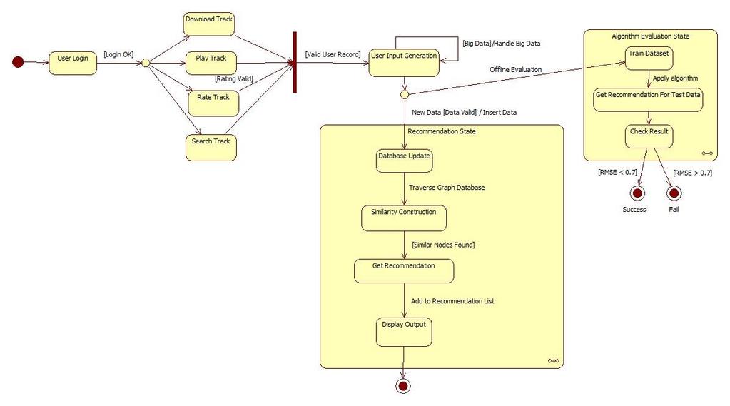
31 Figure 5.13: Web Service Interface This interface can be used by testers. After testing, recommender system will be served as a web service to Argedor State Dynamics Viewpoint This section includes the system behaviour and states of the Recommender System. The states and transitions are illustrated through UML State Machine diagram Design Concerns The statechart in figure illustrates the behaviour of the Recommender System within a larger system. The larger system is a stand-alone music application that our software product is going to be integrated to. The recommender and algorithm evaluation systems are shown as independent substates. The states that remain outside the recommendation and algorithm evaluation states are out of the scope of this project. However, these states and related events are necessary for our software product to proceed. The pre states and post states of the recommender state are assumed to be completely encountered. The host application takes user input through the downloaded, played, rated and search track information. Records for each user are formed and they are supplied to our Web Service. After that point, the state machine either proceeds to 30
32 the recommender state or to the algorithm evaluation state. In the recommender state, the behavior of the web service mainly resides on database transactions. Since the project team uses graph database, the system traverses the large graph, which is actually a storage and notation method for the big user data, to find out the closest match to a user or to a track. In the evaluation state, the algorithm is tested on the user data in offline mode. Some part of the data is used for training while the rest is used for testing. RMSE (Root mean square error) is used in order to evaluate the accuracy of the system. It is a measure of how accurate the recommended songs are according to the actual logs. The threshold value for RMSE is currently fixed as 0.7. If the error gets higher, the system fails. 31
33 32
34 DesignElements The state chart diagram in figure shows all the states, triggers and conditions for each transition and related events. The trigger induces a state change given that the condition is satisfied. The conditions are written inside the square brackets. As soon as the larger system is initialized, User Login state is triggered. It is followed by the login action. If the login information is valid, the user is directed to the actions involving tracks. The user can either download a track, play a track, rate a track or search a track. These states are the main sources for user data. The transition from these states is a synchronized action in order to obtain a complete user data. If the user data is valid, User Input Generation state is initiated. This state has a self-transition due to the big data condition. The project relies on the assumption that the project model is consistent with big data. It is indicated by the Handle Big Data event. As long as there are millions of users and tracks in the system, this state is instantiated again. When the dataset is completed, either the actual recommendation sub state or the algorithm evaluation sub state is triggered. In the recommender sub state, the arrival of new data triggers the database update on the condition that the new data are valid. The insertion event occurs at this point. New data are inserted into the graph database. New nodes and edges are formed inside the huge graph. The next state is Similarity Construction. The event related to this transition is the traversal of graph database. Instead of writing queries in a relational database, the recommender system requires traversing the graph nodes to find the most similar users and tracks. From that point on, if Similar Nodes Found guard is satisfied, the recommendation is generated and displayed to the external system. The algorithm evaluation sub state is triggered on the condition that offline evaluation is demanded. In the first state of this sub state, some part of the user data is trained to the system s recommendation algorithm. Then the rest of the data is used as the test data to check if the recommendations to these test data comply with the actual matches. If expected results are received then the state machine halts successfully. Otherwise, the algorithm fails. 33


35 6. Planning The distribution of tasks among the team members is as follows: Task Graph Traversal Algorithm Component Neo4j Database Component Neo4j API Component Machine Learning Algorithm Component UI Component Weka API Component Evaluator Component Recommender Component Members DuyguKabakcı, Işınsu Katırcıoğlu DuyguKabakcı, Işınsu Katırcıoğlu DuyguKabakcı, Işınsu Katırcıoğlu Sıla Kaya, Mehmet KorayKocakaya Sıla Kaya, DuyguKabakcı Sıla Kaya, Mehmet KorayKocakaya Mehmet KorayKocakaya, Işınsu Katırcıoğlu Sıla Kaya, Mehmet KorayKocakaya The Gantt chart below illustrates the long term planning of the project stages. The dark and light blue regions represent team work whereas other colors represent the workload ofdistinct members or subgroups of the team. Figure 6.1: Gantt chart


36 Figure 6.2: Gantt chart - 2 Figure 6.3: Gantt chart - 3 Figure 6.4: Gantt chart - 4 Figure 6.5: Gantt chart 5 35
37 7. Conclusion This Software Design Description Document includes the system architecture and implementation details of the Recommender System project. In this document, basics of data design, modules and design viewpoints of the system are described respectively. The software tools, frameworks and libraries that will be used while designing and developing the system are also identified. The design issues are specified along with the related design viewpoints. The Gantt chart that covers the project stages of this semester and next semester is provided in order to indicate the major milestones and schema of the project. 36
38 This page intentionally left blank 37
Middle East Technical University Department of Computer Engineering RECOMMENDER SYSTEM. Software Requirements Specification Document V1.
 Middle East Technical University Department of Computer Engineering RECOMMENDER SYSTEM Software Requirements Specification Document V1.1 Dcengo Unchained Duygu Kabakcı 1746064 Işınsu Katırcıoğlu 1819432
SOFTWARE DESIGN DESCRIPTION OF MUSIC RECOMMENDATION SYSTEM
 SOFTWARE DESIGN DESCRIPTION OF MUSIC RECOMMENDATION SYSTEM CENG HISTORY X HACER NİHAL TARKAN AYŞE AYBÜKE TAŞDİREK ASENA OK BİRANT ALTINEL 1 PREFACE This document contains the system design information
Software Design Description Report
 2015 Software Design Description Report CodeBenders Haldun Yıldız 1819663 Onur Aydınay 1819002 Deniz Can Yüksel 1819697 Ali Şihab Akcan 1818871 TABLE OF CONTENTS 1 Overview... 3 1.1 Scope... 3 1.2 Purpose...
SOFTWARE DESIGN DESCRIPTION
 MUSINS-PRO SOFTWARE DESIGN DESCRIPTION CENG490 Yağmur ERTAŞ - 1819333 Duygu ABADAN - 1818863 Baler İLHAN - 1819853 Anıl ARPACI 1818954 1/4/2015 Table of Contents 1. Overview... 3 1.1 Scope... 3 1.2 Purpose...
MIDDLE EAST TECHNICAL UNIVERSITY ENGINEERING FACULTY DEPARTMENT OF COMPUTER ENGINEERING. Vitriol. Software Design Document GROUP MALLORN
 MIDDLE EAST TECHNICAL UNIVERSITY ENGINEERING FACULTY DEPARTMENT OF COMPUTER ENGINEERING Software Design Document GROUP MALLORN Merve Bozo Yaşar Berk Arı Sertaç Kağan Aydın Mustafa Orkun Acar Team Leader:
TETRIS TEAM SMART DRIVER ASSISTANT SOFTWARE DESIGN DESCRIPTIONS. METU-Computer Engineering. 0 P a g e
 METU-Computer Engineering TETRIS TEAM SMART DRIVER ASSISTANT SOFTWARE DESIGN DESCRIPTIONS Team Members: Seymur Mammadli Shkelim Memmola Nail Ibrahimli Mehmet Kurhan 0 P a g e PREFACE This Document contains
SOFTWARE DESIGN DESCRIPTIONS DOCUMENT
 1.12.2013 CENG 490 SOFTWARE DESIGN DESCRIPTIONS DOCUMENT Group 10 The Cereal Killers Members and Signatures Member Signature Date Yaşar Barış ULU 1.12.2013 Kemal Çağın GÜLŞEN 1.12.2013 Mert ERGUN 1.12.2013
SOFTWARE DESIGN DESCRIPTION
 MIDDLE EAST TECHNICAL UNIVERSITY COMPUTER ENGINEERING DEPARTMENT SOFTWARE DESIGN DESCRIPTION Group Name : Smeshers Group Members : Uğur Yanıkoğlu Furkan Odluyurt Dicle Ayzit Emre Barış Advisors : Yusuf
Middle East Technical University. Department of Computer Engineering
 Middle East Technical University Department of Computer Engineering TurkHITs Software Requirements Specifications v1.1 Group fourbytes Safa Öz - 1679463 Mert Bahadır - 1745785 Özge Çevik - 1679414 Sema
HUMAN BODY TRACKING SYSTEM
 HUMAN BODY TRACKING SYSTEM Software Design Description Document V1.1 Mindless Rookies Zehra Deniz Çelik Burak Araz Cem Aydın Yalçın Savrun Revision History Date Revision Comment 03.01.2015 1.0 Created
Middle East Technical University
 ! Middle East Technical University Department of Computer Engineering CONVEYOR Software Design Description Document V1.1 Arctic Donkeys Zeynep Miray Mazlumoğlu - 1819481 Arda Aslan - 1881010 Göksucan Akın
Software Design Description
 Drogba Inc. Software Design Description Ali Hopyar 1746056 Fatih Hafızoğlu 1746049 Halim Kaya 1746148 Volkan Gümüş 1746007 Table of Contents 1 Overview... 3 1.1 Scope... 3 1.2 Purpose... 3 1.3 Intended
SOFTWARE DESIGN DOCUMENT GROUP SUCH CARPOOL SYSTEM
 SOFTWARE DESIGN DOCUMENT GROUP SUCH CARPOOL SYSTEM OVERVIEW TABLE OF CONTENT 1. OVERVIEW... 7 1.1. SCOPE... 7 1.2. PURPOSE... 7 1.3. INTENDED AUDIENCE... 7 2. DEFINITIONS... 8 3. CONCEPTUAL MODEL FOR SOFTWARE
ArchiMate 2.0. Structural Concepts Behavioral Concepts Informational Concepts. Business. Application. Technology
 ArchiMate Core Structural Concepts Behavioral Concepts Informational Concepts interaction Technology Application Layer Concept Description Notation Concept Description Notation Actor An organizational
Software Design Report
 Software design is a process by which the software requirements are translated into a representation of software components, interfaces, and data necessary for the implementation phase. The SDD shows how
SOFTWARE DESIGN DOCUMENT
 SOFTWARE DESIGN DOCUMENT Version: 1.1 Date: 22.12.2013 MobileLibrary Project Prepared By: HebeleGubeleGom Team Ali Sahin Ali Cinar Yunus Emre Avci Upol Ryskulova 1 Preface This document contains the system
Senior Project: Calendar
 Senior Project: Calendar By Jason Chin June 2, 2017 Contents 1 Introduction 1 2 Vision and Scope 2 2.1 Business Requirements...................... 2 2.1.1 Background........................ 2 2.1.2 Business
 iserver Free Archimate ArchiMate 1.0 Template Stencil: Getting from Started Orbus Guide Software Thanks for Downloading the Free ArchiMate Template! Orbus Software have created a set of Visio ArchiMate
SOFTWARE ENGINEERING UML FUNDAMENTALS. Saulius Ragaišis.
 SOFTWARE ENGINEERING UML FUNDAMENTALS Saulius Ragaišis saulius.ragaisis@mif.vu.lt Information source Slides are prepared on the basis of Bernd Oestereich, Developing Software with UML: Object- Oriented
SRI VENKATESWARA COLLEGE OF ENGINERRING AND TECHNOLOGY THIRUPACHUR,THIRUVALLUR UNIT I OOAD PART A
 SRI VENKATESWARA COLLEGE OF ENGINERRING AND TECHNOLOGY THIRUPACHUR,THIRUVALLUR UNIT I OOAD PART A 1. What is an object? An object is a combination of data and logic; the representation of some realworld
Software Engineering Lab Manual
 Kingdom of Saudi Arabia Ministry Education Prince Sattam Bin Abdulaziz University College of Computer Engineering and Sciences Department of Computer Science Software Engineering Lab Manual 1 Background:-
*ANSWERS * **********************************
 CS/183/17/SS07 UNIVERSITY OF SURREY BSc Programmes in Computing Level 1 Examination CS183: Systems Analysis and Design Time allowed: 2 hours Spring Semester 2007 Answer ALL questions in Section A and TWO
Architectural Blueprint
 IMPORTANT NOTICE TO STUDENTS These slides are NOT to be used as a replacement for student notes. These slides are sometimes vague and incomplete on purpose to spark a class discussion Architectural Blueprint
Achieving Right Automation Balance in Agile Projects
 Achieving Right Automation Balance in Agile Projects Vijayagopal Narayanan Vijayagopal.n@cognizant.com Abstract When is testing complete and How much testing is sufficient is a fundamental questions that
LABORATORY 1 REVISION
 UTCN Computer Science Department Software Design 2012/2013 LABORATORY 1 REVISION ================================================================== I. UML Revision This section focuses on reviewing the
Oral Questions. Unit-1 Concepts. Oral Question/Assignment/Gate Question with Answer
 Unit-1 Concepts Oral Question/Assignment/Gate Question with Answer The Meta-Object Facility (MOF) is an Object Management Group (OMG) standard for model-driven engineering Object Management Group (OMG)
Alignment of Business and IT - ArchiMate. Dr. Barbara Re
 Alignment of Business and IT - ArchiMate Dr. Barbara Re What is ArchiMate? ArchiMate is a modelling technique ("language") for describing enterprise architectures. It presents a clear set of concepts within
Fundamentals to Creating Architectures using ISO/IEC/IEEE Standards
 Fundamentals to Creating Architectures using ISO/IEC/IEEE Standards What to Architect? How to Architect? IEEE Goals and Objectives Chartered by IEEE Software Engineering Standards Committee to: Define
Smart Driver Assistant Software Requirements Specifications
 2016 Software Requirements Specifications SEYMUR MAMMADLI SHKELQIM MEMOLLA NAIL IBRAHIMLI MEHMET KURHAN MIDDLE EAST TECHNICAL UNIVERSITY Department Of Computer Engineering Preface This document contains
Passport Automation System
 1.Objective: To develop the passport automation system software using UML language. It is the interface between applicant and authority responsible for issue the passport. It aims at improving efficiency
SOFTWARE MODELING AND DESIGN. UML, Use Cases, Patterns, and. Software Architectures. Ki Cambridge UNIVERSITY PRESS. Hassan Gomaa
 SOFTWARE MODELING AND DESIGN UML, Use Cases, Patterns, and Software Architectures Hassan Gomaa George Mason University, Fairfax, Virginia Ki Cambridge UNIVERSITY PRESS Contents Preface P"U
Software Service Engineering
 Software Service Engineering Lecture 4: Unified Modeling Language Doctor Guangyu Gao Some contents and notes selected from Fowler, M. UML Distilled, 3rd edition. Addison-Wesley Unified Modeling Language
Guideal SOFTWARE TEST DOCUMENT. (In accordance with IEEE ) v1.0
 v1.0") Guideal SOFTWARE TEST DOCUMENT (In accordance with IEEE 829-2008 ) v1.0 Malum Emre Külah 1881358 Arif Görkem Özer 1881747 Yusuf Mücahit Çetinkaya 1881705 Semih Aktaş 1880913 Version Control History: Version
Guideal SOFTWARE TEST DOCUMENT (In accordance with IEEE 829-2008 ) v1.0 Malum Emre Külah 1881358 Arif Görkem Özer 1881747 Yusuf Mücahit Çetinkaya 1881705 Semih Aktaş 1880913 Version Control History: Version
Unit Wise Questions. Unit-1 Concepts
 Unit Wise Questions Unit-1 Concepts Q1. What is UML? Ans. Unified Modelling Language. It is a Industry standard graphical language for modelling and hence visualizing a blue print of all the aspects of
Presenter: Dong hyun Park
 Presenter: 200412325 Dong hyun Park Design as a life cycle activity bonds the requirements to construction Process of breaking down the system into components, defining interfaces and defining components
Practical UML : A Hands-On Introduction for Developers
 Borland.com Borland Developer Network Borland Support Center Borland University Worldwide Sites Login My Account Help Search Practical UML : A Hands-On Introduction for Developers - by Randy Miller Rating:
3rd Lecture Languages for information modeling
 3rd Lecture Languages for information modeling Agenda Languages for information modeling UML UML basic concepts Modeling by UML diagrams CASE tools: concepts, features and objectives CASE toolset architecture
Proposed Revisions to ebxml Technical. Architecture Specification v1.04
 Proposed Revisions to ebxml Technical Architecture Specification v1.04 Business Process Team 11 May 2001 (This document is the non-normative version formatted for printing, July 2001) Copyright UN/CEFACT
UNIT-I Introduction of Object Oriented Modeling
 UNIT-I Introduction of Object Oriented Modeling - Prasad Mahale Object Oriented Modeling and Reference Books: Design 1. Grady Booch, James Rumbaugh, Ivar Jacobson Unified Modeling Language User Guide,
<Company Name> <Project Name> Software Requirements Specification For <Subsystem or Feature> Version <1.0>
 For Version [Note: The following template is provided for use with the Rational Unified Process. Text enclosed in square brackets and displayed
Implementation Architecture
 Implementation Architecture Software Architecture VO/KU (707023/707024) Roman Kern ISDS, TU Graz 2017-11-15 Roman Kern (ISDS, TU Graz) Implementation Architecture 2017-11-15 1 / 54 Outline 1 Definition
Rational Software White paper
 Unifying Enterprise Development Teams with the UML Grady Booch Rational Software White paper 1 There is a fundamental paradox at play in contemporary software development. On the one hand, organizations
Software Design Document (SDD) Template (summarized from IEEE STD 1016)
 Template (summarized from IEEE STD 1016)") Software Design Document (SDD) Template (summarized from IEEE STD 1016) Software design is a process by which the software requirements are translated into a representation of software components, interfaces,
Software Design Document (SDD) Template (summarized from IEEE STD 1016) Software design is a process by which the software requirements are translated into a representation of software components, interfaces,
Lecture 8 Requirements Engineering
 Lecture 8 Requirements Engineering Software Engineering ITCS 3155 Fall 2008 Dr. Jamie Payton Department of Computer Science University of North Carolina at Charlotte September 18, 2008 Lecture Overview
Examples. Object Orientated Analysis and Design. Benjamin Kenwright
 Examples Object Orientated Analysis and Design Benjamin Kenwright Outline Revision Questions Group Project Review Deliverables Example System Problem Case Studey Group Project Case-Study Example Vision
SYSTEM DESIGN DOCUMENT
 2013 Leş Koding Baran KÜÇÜKGÜZEL Batuhan TAŞDÖVEN Ali Barış UZUNER Bekir ÖZTÜRK SYSTEM DESIGN DOCUMENT This document is prepared by Leş Koding s members; the document is about system design description
Software Requirements Specification (IEEE Std )[1] V1.0. NoNET. Prepared by FixIT
![Software Requirements Specification (IEEE Std )[1] V1.0. NoNET. Prepared by FixIT](/thumbs/85/92094470.jpg "Software Requirements Specification (IEEE Std )[1] V1.0. NoNET. Prepared by FixIT") Software Requirements Specification (IEEE Std 830-1998)[1] V1.0 NoNET Prepared by FixIT Ceyda Tosun-1819580 Gülşah Sabırsız-1881424 Gulnaz Shaidolda-1784578 METU - Department of Computer Engineering CENG
Software Requirements Specification (IEEE Std 830-1998)[1] V1.0 NoNET Prepared by FixIT Ceyda Tosun-1819580 Gülşah Sabırsız-1881424 Gulnaz Shaidolda-1784578 METU - Department of Computer Engineering CENG
COMPUTER/INFORMATION FLOOD STANDARDS
 COMPUTER/INFORMATION FLOOD STANDARDS CIF-1 Flood Model Documentation A. Flood model functionality and technical descriptions shall be documented formally in an archival format separate from the use of
ISO/IEC/ IEEE INTERNATIONAL STANDARD. Systems and software engineering Architecture description
 INTERNATIONAL STANDARD ISO/IEC/ IEEE 42010 First edition 2011-12-01 Systems and software engineering Architecture description Ingénierie des systèmes et des logiciels Description de l'architecture Reference
SOFTWARE REQUIREMENT SPECIFICATION OF MUSIC RECOMMENDATION SYSTEM CENG HISTORY X HACER NİHAL TARKAN AYŞE AYBÜKE TAŞDİREK ASENA OK BİRANT ALTINEL
 SOFTWARE REQUIREMENT SPECIFICATION OF MUSIC RECOMMENDATION SYSTEM CENG HISTORY X HACER NİHAL TARKAN AYŞE AYBÜKE TAŞDİREK ASENA OK BİRANT ALTINEL 1 TABLE OF CONTENTS 1. Introduction...4 1.1 Problem Definition...4
4.2.2 Usability. 4 Medical software from the idea to the finished product. Figure 4.3 Verification/validation of the usability, SW = software
 4.2.2 Usability Intended purpose, Market Validation Usability Usability Risk analysis and measures Specification of the overall system SW SW architecture/ of SW SW design Software design & integration
Lecture 13 Introduction to Software Architecture
 Lecture 13 Introduction to Software Architecture Software Systems Design and Implementation ITCS/ITIS 6112/8112 Fall 2008 Dr. Jamie Payton Department of Computer Science University of North Carolina at
COMPUTER FLOOD STANDARDS
 COMPUTER FLOOD STANDARDS CF-1 Flood Model Documentation A. Flood model functionality and technical descriptions shall be documented formally in an archival format separate from the use of letters, slides,
SOFTWARE DESIGN DESCRIPTION
 2013 Leş Koding Baran KÜÇÜKGÜZEL Batuhan TAŞDÖVEN Ali Barış UZUNER Bekir ÖZTÜRK SOFTWARE DESIGN DESCRIPTION This document is prepared by Leş Koding s members; the document is about software design description
System and Software Architecture Description (SSAD)
") System and Software Architecture Description (SSAD) Tipsure.com Team# 09 Member Name Jonathan Tuse Raymond Feng David Brenn-Cogen Aayushi Birla Tej Trivedi Nirupama Vaidyanathan Linkun Li Primary Role
System and Software Architecture Description (SSAD) Tipsure.com Team# 09 Member Name Jonathan Tuse Raymond Feng David Brenn-Cogen Aayushi Birla Tej Trivedi Nirupama Vaidyanathan Linkun Li Primary Role
Project Requirements
 Project Requirements Version 4.0 2 May, 2016 2015-2016 Computer Science Department, Texas Christian University Revision Signatures By signing the following document, the team member is acknowledging that
UNIT 5 - UML STATE DIAGRAMS AND MODELING
 UNIT 5 - UML STATE DIAGRAMS AND MODELING UML state diagrams and modeling - Operation contracts- Mapping design to code UML deployment and component diagrams UML state diagrams: State diagrams are used
BUILDING MICROSERVICES ON AZURE. ~ Vaibhav
 BUILDING MICROSERVICES ON AZURE ~ Vaibhav Gujral @vabgujral About Me Over 11 years of experience Working with Assurant Inc. Microsoft Certified Azure Architect MCSD, MCP, Microsoft Specialist Aspiring
HPE Enterprise Maps Data Model, ArchiMate, TOGAF. HPE Software, Cloud and Automation
 HPE Enterprise Maps Data Model, ArchiMate, TOGAF HPE Software, Cloud and Automation Data Model Enterprise Maps ArchiMate Overview Modeling language for EA 2002-2004 - NL university + government + industry
Enterprise Architect Training Courses
 On-site training from as little as 135 per delegate per day! Enterprise Architect Training Courses Tassc trainers are expert practitioners in Enterprise Architect with over 10 years experience in object
DLV02.01 Business processes. Study on functional, technical and semantic interoperability requirements for the Single Digital Gateway implementation
 Study on functional, technical and semantic interoperability requirements for the Single Digital Gateway implementation 18/06/2018 Table of Contents 1. INTRODUCTION... 7 2. METHODOLOGY... 8 2.1. DOCUMENT
SOFTWARE DESIGN COSC 4353 / Dr. Raj Singh
 SOFTWARE DESIGN COSC 4353 / 6353 Dr. Raj Singh UML - History 2 The Unified Modeling Language (UML) is a general purpose modeling language designed to provide a standard way to visualize the design of a
Lab Manual. Object Oriented Analysis And Design. TE(Computer) VI semester
 VI semester") Lab Manual Object Oriented Analysis And Design TE(Computer) VI semester Index Sr. No. Title of Programming Assignment Page No. 1 2 3 4 5 6 7 8 9 10 Study of Use Case Diagram Study of Activity Diagram Study
Lab Manual Object Oriented Analysis And Design TE(Computer) VI semester Index Sr. No. Title of Programming Assignment Page No. 1 2 3 4 5 6 7 8 9 10 Study of Use Case Diagram Study of Activity Diagram Study
(Team Name) (Project Title) Software Design Document. Student Name (s):
 (Project Title) Software Design Document. Student Name (s):") (Team Name) (Project Title) Software Design Document Student Name (s): TABLE OF CONTENTS 1. INTRODUCTION 2 1.1Purpose 2 1.2Scope 2 1.3Overview 2 1.4Reference Material 2 1.5Definitions and Acronyms 2 2.
(Team Name) (Project Title) Software Design Document Student Name (s): TABLE OF CONTENTS 1. INTRODUCTION 2 1.1Purpose 2 1.2Scope 2 1.3Overview 2 1.4Reference Material 2 1.5Definitions and Acronyms 2 2.
DoDAF 2.0 Viewpoint Definitions. DoDAF v2.0 Viewpoint Definitions
 DoDAF v2.0 Viewpoint Definitions i Copyright 2011-2016 Vitech Corporation. All rights reserved. No part of this document may be reproduced in any form, including, but not limited to, photocopying, translating
Implementation Architecture
 Implementation Architecture Software Architecture VO/KU (707023/707024) Roman Kern KTI, TU Graz 2014-11-19 Roman Kern (KTI, TU Graz) Implementation Architecture 2014-11-19 1 / 53 Outline 1 Definition 2
Avancier Methods (AM) CONCEPTS
 CONCEPTS") Methods (AM) CONCEPTS Mapping generic ArchiMate entities to and TOGAF meta model entities It is illegal to copy, share or show this document (or other document published at ) without the written permission
Methods (AM) CONCEPTS Mapping generic ArchiMate entities to and TOGAF meta model entities It is illegal to copy, share or show this document (or other document published at ) without the written permission
The Web Service Sample
 The Web Service Sample Catapulse Pacitic Bank The Rational Unified Process is a roadmap for engineering a piece of software. It is flexible and scalable enough to be applied to projects of varying sizes.
Proposed Revisions to ebxml Technical Architecture Specification v ebxml Business Process Project Team
 1 2 3 4 5 6 7 8 9 10 11 12 13 14 15 16 17 18 19 20 21 22 23 24 25 26 27 28 29 30 31 32 33 Proposed Revisions to ebxml Technical Architecture Specification v1.0.4 ebxml Business Process Project Team 11
Experiment no 4 Study of Class Diagram in Rational Rose
 Experiment no 4 Study of Class Diagram in Rational Rose Objective-: To studyclass Diagram in Rational Rose. References-: www.developer.com The Unified Modeling Language User Guide by Grady Booch Mastering
Practical Database Design Methodology and Use of UML Diagrams Design & Analysis of Database Systems
 Practical Database Design Methodology and Use of UML Diagrams 406.426 Design & Analysis of Database Systems Jonghun Park jonghun@snu.ac.kr Dept. of Industrial Engineering Seoul National University chapter
[Product] MTM Program Product Software Requirements Specification
![[Product] MTM Program Product Software Requirements Specification](/thumbs/89/98496075.jpg "[Product] MTM Program Product Software Requirements Specification") [Product] Software Requirements Specification [Version Number] [Version Date] [Product] MTM Program Product Software Requirements Specification [SRS Version Number] [SRS Version Date] [Applying MTM SRS
[Product] Software Requirements Specification [Version Number] [Version Date] [Product] MTM Program Product Software Requirements Specification [SRS Version Number] [SRS Version Date] [Applying MTM SRS
UML Unified Modeling Language
 UML Unified Modeling Language a standard language to analyze, design and document software intensive solutions Modeling with UML Building blocks When you model something, you create a simplification of
S1 Informatic Engineering
 S1 Informatic Engineering Advanced Software Engineering Web App. Process and Architecture By: Egia Rosi Subhiyakto, M.Kom, M.CS Informatic Engineering Department egia@dsn.dinus.ac.id +6285640392988 SYLLABUS
Software Design Document
 SCSJ2203: Software Engineering Software Design Document Project Title Version 1.0 Printing Date Department and Faculty Prepared by: Revision Page a. Overview Describe the content
Practical UML - A Hands-On Introduction for Developers
 Practical UML - A Hands-On Introduction for Developers By: Randy Miller (http://gp.codegear.com/authors/edit/661.aspx) Abstract: This tutorial provides a quick introduction to the Unified Modeling Language
CTI Short Learning Programme in Internet Development Specialist
 CTI Short Learning Programme in Internet Development Specialist Module Descriptions 2015 1 Short Learning Programme in Internet Development Specialist (10 months full-time, 25 months part-time) Computer
Building the User Interface: The Case for Continuous Development in an Iterative Project Environment
 Copyright Rational Software 2002 http://www.therationaledge.com/content/dec_02/m_uiiterativeenvironment_jc.jsp Building the User Interface: The Case for Continuous Development in an Iterative Project Environment
2.0.3 attributes: A named property of a class that describes the range of values that the class or its instances (i.e., objects) may hold.
 may hold.") T0/04-023 revision 2 Date: September 06, 2005 To: T0 Committee (SCSI) From: George Penokie (IBM/Tivoli) Subject: SAM-4: Converting to UML part Overview The current SCSI architecture follows no particular
T0/04-023 revision 2 Date: September 06, 2005 To: T0 Committee (SCSI) From: George Penokie (IBM/Tivoli) Subject: SAM-4: Converting to UML part Overview The current SCSI architecture follows no particular
Data Mining: STATISTICA
 Outline Data Mining: STATISTICA Prepare the data Classification and regression (C & R, ANN) Clustering Association rules Graphic user interface Prepare the Data Statistica can read from Excel,.txt and
Pattern for Structuring UML-Compatible Software Project Repositories
 Pattern for Structuring UML-Compatible Software Project Repositories Pavel Hruby Navision Software a/s Frydenlunds Allé 6 2950 Vedbaek, Denmark E-mail: ph@navision.com Web site: www.navision.com/services/methodology/default.asp
IS 0020 Program Design and Software Tools
 1 IS 0020 Program Design and Software Tools Unified Modeling Language Lecture 13 April 13, 2005 What is UML? 2 The Unified Modelling Language is a standard notation to model [object oriented] systems.
A Tutorial on Agent Based Software Engineering
 A tutorial report for SENG 609.22 Agent Based Software Engineering Course Instructor: Dr. Behrouz H. Far A Tutorial on Agent Based Software Engineering Qun Zhou December, 2002 Abstract Agent oriented software
Full Stack Developer with Java
 Full Stack Developer with Java Full Stack Developer (Java) MVC, Databases and ORMs, API Backend Frontend Fundamentals - HTML, CSS, JS Unit Testing Advanced Full Stack Developer (Java) UML, Distributed
Software Requirements Specification (SRS) Graphical Model Editing Framework (GMEF) Motorola 1
 Graphical Model Editing Framework (GMEF) Motorola 1") Software Requirements Specification (SRS) Graphical Model Editing Framework (GMEF) Motorola 1 Final Draft Due December 7, 2006 Authors: Greg Heil, Andrew Holder, Karli Lopez, Josh Detwiler Customer: Kabe
Software Requirements Specification (SRS) Graphical Model Editing Framework (GMEF) Motorola 1 Final Draft Due December 7, 2006 Authors: Greg Heil, Andrew Holder, Karli Lopez, Josh Detwiler Customer: Kabe
Chapter 1: Programming Principles
 Chapter 1: Programming Principles Object Oriented Analysis and Design Abstraction and information hiding Object oriented programming principles Unified Modeling Language Software life-cycle models Key
CTI Higher Certificate in Information Systems (Internet Development)
") CTI Higher Certificate in Information Systems (Internet Development) Module Descriptions 2015 1 Higher Certificate in Information Systems (Internet Development) (1 year full-time, 2½ years part-time) Computer
CTI Higher Certificate in Information Systems (Internet Development) Module Descriptions 2015 1 Higher Certificate in Information Systems (Internet Development) (1 year full-time, 2½ years part-time) Computer
Architectural Blueprint The 4+1 View Model of Software Architecture. Philippe Kruchten
 Architectural Blueprint The 4+1 View Model of Software Architecture Philippe Kruchten Model What is a model? simplified abstract representation information exchange standardization principals (involved)
Product Requirements for Data Dwarf. Revisions
 Product Requirements for Data Dwarf Prepared by Sean Spearman Cody Brown Ray Smets Aimee Galang Tim Shen Mercury Squad seanmspeaman@gmail.com codybrwn551@aol.com rayjsmets@gmail.com aimeegalang@gmail.com
Object-Oriented Analysis and Design Using UML
 Object-Oriented Analysis and Design Using UML Student Guide - Volume 1 OO-226 Rev C D61808GC10 Edition 1.0 D62408 Copyright 2003, 2009, Oracle and/or its affiliates. All rights reserved. Disclaimer This
Basic Structural Modeling. Copyright Joey Paquet,
 Basic Structural Modeling Copyright Joey Paquet, 2000 1 Part I Classes Copyright Joey Paquet, 2000 2 Classes Description of a set of objects sharing the same attributes, operations and semantics Abstraction
Recalling the definition of design as set of models let's consider the modeling of some real software.
 Software Design and Architectures SE-2 / SE426 / CS446 / ECE426 Lecture 3 : Modeling Software Software uniquely combines abstract, purely mathematical stuff with physical representation. There are numerous
Analysis and Design with UML
 Analysis and Design with UML Page 1 Agenda Benefits of Visual Modeling History of the UML Visual Modeling with UML The Rational Iterative Development Process Page 2 What is Visual Modeling? Item Order
Data Warehouse and Data Mining
 Data Warehouse and Data Mining Lecture No. 05 Data Modeling Naeem Ahmed Email: naeemmahoto@gmail.com Department of Software Engineering Mehran Univeristy of Engineering and Technology Jamshoro Data Modeling
SCOS-2000 Technical Note
 SCOS-2000 Technical Note MDA Study Prototyping Technical Note Document Reference: Document Status: Issue 1.0 Prepared By: Eugenio Zanatta MDA Study Prototyping Page: 2 Action Name Date Signature Prepared
UML-Based Conceptual Modeling of Pattern-Bases
 UML-Based Conceptual Modeling of Pattern-Bases Stefano Rizzi DEIS - University of Bologna Viale Risorgimento, 2 40136 Bologna - Italy srizzi@deis.unibo.it Abstract. The concept of pattern, meant as an
2.0.3 attributes: A named property of a class that describes the range of values that the class or its instances (i.e., objects) may hold.
 may hold.") T0/06-6 revision 0 Date: March 0, 2006 To: T0 Committee (SCSI) From: George Penokie (IBM/Tivoli) Subject: SAM-4: Converting to UML part Overview The current SCSI architecture follows no particular documentation
T0/06-6 revision 0 Date: March 0, 2006 To: T0 Committee (SCSI) From: George Penokie (IBM/Tivoli) Subject: SAM-4: Converting to UML part Overview The current SCSI architecture follows no particular documentation
Sofware Requirements Engineeing
 Sofware Requirements Engineeing Three main tasks in RE: 1 Elicit find out what the customers really want. Identify stakeholders, their goals and viewpoints. 2 Document write it down (Requirements Specification).
Creating and Analyzing Software Architecture
 Creating and Analyzing Software Architecture Dr. Igor Ivkovic iivkovic@uwaterloo.ca [with material from Software Architecture: Foundations, Theory, and Practice, by Taylor, Medvidovic, and Dashofy, published
Chapter 4 Objectives
 Chapter 4 Objectives Eliciting requirements from the customers Modeling requirements Reviewing requirements to ensure their quality Documenting requirements for use by the design and test teams 4.1 The