Network Camera Operation Manual K-EF235L01E
|
|
|
- Gervase Hunter
- 5 years ago
- Views:
Transcription
1 Network Camera Operation Manual Model No. K-EW215L01E K-EF235L01E Version 1.0.0
2 Table of Contents 1 Network Connection Main Interface Introduction Log in Live Interface Encode Setup Image Adjustment System Menu Video Window Function Option Zoom and Focus Setup Basic Image adjust Image Conditions Profile Management Network TCP/IP Connection PPPoE DDNS SMTP ( ) UPnP Bonjour Multicast x QoS HTTPS Event Video Detection Abnormity Storage Schedule Destination Record Control System Account (User mng.) Safety(IP Filter) Default reset Import/Export Auto Maintenance Upgrade Information i
3 3.7.1 Version Log Online User Playback Playback Function of Play Playback File Playback Cut Record Type Progress Bar Assistant Function Picture Playback Play Playback File Snapshot Type Alarm Log out ii
4 Welcome Thank you for purchasing our network camera! This operation manual is designed to be a reference tool for your system. Please open the accessory bag to check the items one by one. Depending on the model used, the screens shown in the explanations may differ to the actual camera screens. iii
5 1 Network Connection These series network camera products support the Web access and management via PC. Web includes several modules: monitor channel preview, system configuration, alarm and etc. Please follow the steps listed below for network connection. Make sure the network camera has connected to the network properly. Network camera IP address and PC IP address shall be in the same network segment. If there is router, please set the corresponding gateway and subnet mask. Use order ping ***.***.***.***(* network camera address) to check connection is OK or not. 1
6 2 Main Interface Introduction 2.1 Log in Open IE and input network camera address in the address bar. For example, if your camera IP is , then please input in IE address bar. See Figure 2-1. Input your IP address here Figure 2-1 The Device Initialization interface is shown as below. See Figure 2-2. Set the password of admin account. Password/confirm password: The password ranges from 8 to 32 digitals. It can contain letters, numbers and special characters (excluding ', ", ;, :, & ). The password shall contain at least three categories. Usually we recommend the strong password. Note: To ensure device safety, please keep the password properly after initialization and change the password regularly. 2

7 Figure 2-2 3

8 If it is your first time to login in, you may see the interface shown as in Figure 2-3. Figure 2-3 Click on Please click here to download and install the plug-in. The system pops up warning information to ask you whether run or save this plug-in. See Figure 2-4. Figure 2-4 You must either run or save the file to local and install it. Follow the following steps. See Figure 2-5. Note: The displayed screens are different by the security settings on the PC. 4

9 Figure 2-5 When plug-in installation completes, the installation page closes automatically. The web-end will refresh automatically, and then you can view video captured by the camera. 5

10 2.2 Live Interface After you logged in, you can see the live monitor window. See Figure Figure 2-6 There are three sections: Section 1: Encode setup bar Section 2: System menu Section 3: Window function option bar 6
 and (Sub) 2 Protocol You can select stream media protocol from the dropdown list.")
11 2.3 Encode Setup The encode setup interface is shown as in Figure Figure 2-7 Please refer to the following sheet for detailed information. SN Parameter Function 1 Stream You can switch Stream(Main) and (Sub) 2 Protocol You can select stream media protocol from the dropdown list. There are three options: TCP/UDP/Multicast 3 Digital Zoom When the video is in the original status, click it you can select any zone to zoom in. In the non-original status, you can drag the zoom-in zone in specified range. Right click mouse to restore previous status. Click it; you can use the middle button of the mouse to zoom in/out the video size. 7


12 4 Image Adjustment You can adjust image quality. 5 Alarm It moves to an alarm setting screen. 6 Playback It moves to a playback screen. 7 Logout Click Logout button, system goes back to log in interface Image Adjustment Click Image Adjustment button to open picture setup interface. See Figure 2-8. This interface is displayed under a display of Image Adjustment. Figure 2-8 Please refer to the following sheet for detailed information. Parameter Function Video setup It is to adjust monitor video brightness. It is to adjust monitor video contrast. It is to adjust monitor video hue. It is to adjust monitor video saturation. Note: All the operations here apply to WEB end only. Please go to Setup -> Image -> Image adjust to adjust corresponding items. 8

13 Reset Restore brightness, contrast saturation and hue to system default setup. 2.4 System Menu System menu is a click Setup as in Figure 2-9. Please refer to chapter 3.1 Basic, chapter 3.2 Image adjust, chapter 3.3 Network, chapter 3.4 Event, chapter 3.5 Storage, chapter 3.6 System, and chapter 3.7 Information for detailed information. Figure 2-9 9
14 2.5 Video Window Function Option The interface is shown as below. See Figure Figure 2-10 Please refer to the following sheet for detailed information. SN Parameter Function 1 Original Click this button to go to original size. It is to display the actual Size size of the video stream. It depends on the resolution of the bit stream. 2 Full Screen Click it to go to full-screen mode. Double click the mouse or 3 Width and Height ratio 4 Fluency Adjustment 5 Zoom and Focus click the Esc button to exit the full screen. Click it to restore original ratio or suitable window. There are three levels of fluency for you to select. The default is real-time with minimum delay. You may select fluent mode in case connection is slow. Click this button and the zoom and focus interface appears on encode setup bar 6 Snapshot You can snapshot important video by clicking on this button. All images are memorized in system folder: \ picture download (default). You can go to Setup -> Image adjust-> image -> Path to modify the local record save path. 7 Triple Snapshot Click it, system can snap at 1 fps. All images are memorized in system storage folder. 8 Record For manual record. All records are memorized in Setup -> Image Adjust -> Image -> Path. 10


15 9 Easy focus Click the icon, the AF Peak (focus eigenvalue) and AF Max (max focus eigenvalue) display on the video. AF Peak: the eigenvalue of image resolution, the realtime value displays when focusing. AF Max: the best eigenvalue of image resolution. The closer AF peak value and AF Max value are, the better the focus is. Easy focus closes automatically after five minutes Zoom and Focus Click this button and the zoom and focus interface appears on the encode setup bar, as shown in Figure 2-11, please refer to the following sheet for detail information to adjust zoom and focus configuration. Note: Auto-focus after zoom focus adjustment. Disable the operation till finishing zoom and focus adjustment. Figure
16 Parameter Zoom Focus Auto Focus Restore All Refresh Function Adjust the focal length of the lens by clicking or long pressing + - buttons or moving the slider. Step length (Speed) is used to adjust the length of one step with one click. Adjust the sharpness length of the lens by clicking or long pressing + - buttons or moving the slider. Step length (Speed) is used to adjust the length of one step with one click. Click to adjust the image definition automatically. Note: Other lens operations are not allowed during the process of auto-focus. Reset the lens to zero position to eliminate the accumulative error of lens. Note: Please reset when the image adjustment is not clear or operating zoom focus many times. Synchronize the location of drag slider of lens and zoom focus after hardware zoom focusing. 12
17 3 Setup 3.1 Basic The basic interface includes the local host setup and the date/time setup. The date and time interface is shown as in Figure 3-1. Figure 3-1 Please refer to the following sheet for detailed information. Parameter Name Current time Time format Date format Time zone DST Type Function It is to set device name. Set date and time. Click Sync PC to set PC time to camera. There are two options: 24-H and 12-H. Here you can select date format from the dropdown list. The time zone of the device. Here you can set daylight saving time begin time and end time. You can set according to the date format or according to the week format. 13
18 Camera title/time on screen Language Video Standard NTP Setup NTP Server NTP Port Update period Link Overlay ( Image adjust -> Image -> Overlay) You can select the language from the dropdown list. This is to display video standard such as NTSC. You can check the box to enable NTP function. You can set the time server address. It is to set the time server port. It is to set the sync periods between the device and the time server. 14
 encode and H.265 encode. H.264H : High Profile encode mode. H.265 : Main Profile Encode Mode Enable smart codec to improve video compressibility and save storage space.")
19 3.2 Image adjust Image Image The video bit stream interface is shown as below. See Figure 3-2. Figure 3-2 Please refer to the following sheet for detailed information. Parameter Main Stream Encode Mode Smart Codec Function There are two options: H.264H (high profile standard) encode and H.265 encode. H.264H : High Profile encode mode. H.265 : Main Profile Encode Mode Enable smart codec to improve video compressibility and save storage space. Note: After smart codec is enabled, the device would stop supporting ROI and smart event detection, and the actual interface shall prevail. Resolution There are multiple resolutions. You can select from the dropdown list. For each resolution, the recommended bit stream value is different. 15
20 Parameter Function Frame rate(fps) Bite Rate Type Reference Bit Rate NTSC: 1-30fps. The frame rate may vary due to different resolutions. There are two options: VBR and CBR. Please note, you can set video quality in VBR mode. Reference bit rate value according to the resolution and frame rate you have set. Bit Rate In VBR, the bit rate here is the max value. In CBR, it is a fixed value. See reference bit stream for recommended value. Sub Stream I Frame interval Watermark Settings / Watermark Character Enable Compression Resolution Frame rate(fps) Bit Rate Type Here you can set the P frame amount between two I frames. The value ranges from 1 to 150. Default value is 60. Recommended value is frame rate. Select the check box to enable watermark function. You can verify the watermark to check if the video has been tampered. Default character is DigitalCCTV. The character can only include number, character and underline. Please check the box here to enable Sub stream function. This function is enabled by default. There are three options: H.264H (high profile standard) encode, H.265 encode and MJPEG encode. H.264H : High Profile encode mode. H.265 : Main Profile Encode Mode MJPEG: In this encode mode, the video needs to large bit stream to guarantee the video definition. You can use the max bit stream value in the recommend bit to get the better video output effect. There are multiple resolutions. You can select from the dropdown list. For each resolution, the recommended bit stream value is different. NTSC: 1-30fps. The frame rate may vary due to different resolutions. There are two options: VBR and CBR. Please note, you can set video quality in VBR mode. 16
21 Parameter Function Reference Bit Rate Reference bit rate value according to the resolution and frame rate you have set. Bit Rate In CBR, the bit rate here is the max value. In dynamic video, system needs to low frame rate or video quality to guarantee the value. The value is null in VBR mode. Please refer to recommend bit rate for the detailed information. I Frame interval Here you can set the P frame amount between two I frames. The value ranges from 1 to 150. Default value is 60. Recommended value is frame rate. 17
 and Event (activation). It is the same with the resolution of the Main stream.")
22 Snapshot The snapshot interface is shown as in Figure 3-3. Figure 3-3 Please refer to the following sheet for detailed information. Parameter Snapshot Type Image size Quality Function There are two modes: general (schedule) and Event (activation). It is the same with the resolution of the Main stream. It is to set the image quality. There are six levels. Interval It is to set snapshot frequency. The value ranges from 1s to 7s. 18

23 Overlay The video overlay interface is shown as in Figure 3-4, 3-5, 3-6, 3-7. Figure 3-4 Figure

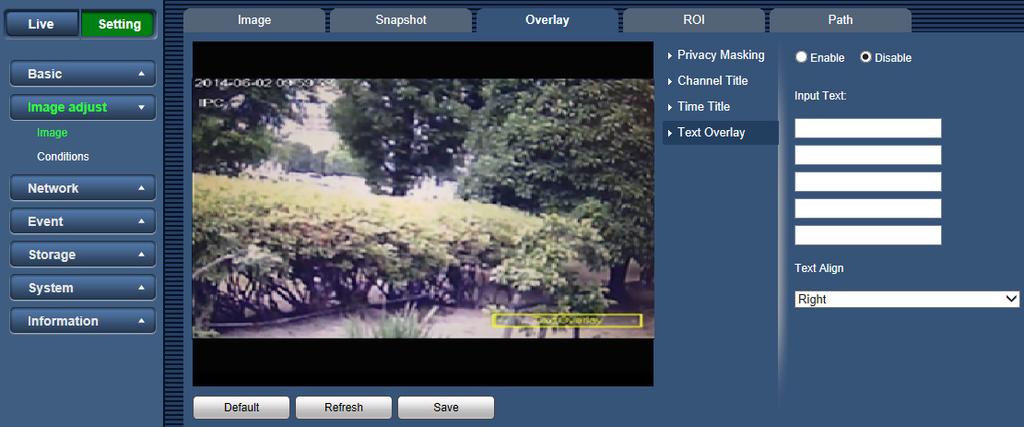
24 Figure 3-6 Figure
25 Please refer to the following sheet for detailed information. Parameter Privacy Masking Function Here you can privacy mask the specified video in the monitor video. System max supports 4 privacy mask zones. See Figure 3-4 Channel title You can enable this function so that system overlays channel information in video window. You can use the mouse to drag the channel tile position. See Figure 3-5 Time Title You can enable this function so that system overlays time information in video window. You can use the mouse to drag the time tile position. See Figure 3-6 Test Overlay You can enable this function so that system overlays location information in video window. To change text alignment, you can select by dropdown list. See Figure

26 ROI The ROI function can change the data size of images before sending them by performing operations such as increasing the resolution of important monitoring areas in the image and reducing the resolution of other areas. See Figure 3-8. Figure 3-8 Parameters Enable Image Quality Note Check Enable, then it will display the ROI in the video monitoring window. Set the image quality of ROI, ranging from 1~6(best), default is 6(best). Able to set area block, max 4 areas Path The storage path interface is shown as in Figure 3-9. You can set the storage path for live snapshot, live record, playback snapshot, playback download and video clips. Parameter live snapshot live record Playback Snapshot Description Live Snapshot refers to the snapshot of live interface. The default path is C:\Users\admin\WebDownload\LiveSnapshot. Live Record refers to the recorded video of live interface. The default path is C:\Users\admin\WebDownload\LiveRecord. Playback Snapshot refers to the snapshot of playback interface. The default path is C:\Users\admin\WebDownload\PlaybackSnapshot. 22

27 playback download video clips Playback Download refers to the downloaded video of playback interface. The default path is C:\Users\admin\WebDownload\PlaybackRecord. Video Clips refer to the clipped video of playback interface. The default path is C:\Users\admin\WebDownload\VideoClips. Note: admin means the account being used. Please click the Save button to save current setup. Figure Conditions Here you can view device property information. Slight differences may be found due to different network camera series. The setups become valid immediately after you set. See Figure Figure
28 Please refer to the following sheet for detailed information. Parameter Profile Style Picture/Brightness Picture/Contrast Picture/Saturation Picture/Sharpness Picture/Gamma Picture/Mirror Function You may select normal, day and night mode. Select picture style from soft, standard and vivid. It is to adjust monitor window bright. You can adjust this value if the video is too dark or too bright. The larger the number, the bright the video is. When you input the value here, the bright section and the dark section of the video will be adjusted accordingly. Please note the video may become hazy if the value is too high. The value ranges from 0 to 100. The recommended value ranges from 40 to 60. The default value is 50. It is to adjust monitor window contrast. The larger the number, the higher the contrast is. You can use this function when the whole video bright is OK but the contrast is not proper. Please note the video may become hazy if the value is too low. If this value is too high, the dark section may lack brightness while the bright section may over exposure. The value ranges from 0 to 100. The recommended value ranges from 40 to 60. The default value is 50. It is to adjust monitor window saturation. The larger the number, the strong the color is. This value has no effect on the general brightness of the whole video. The video color may become too strong if the value is too high. For the grey part of the video, the distortion may occur if the white balance is not accurate. Please note the video may not be attractive if the value is too low. The value ranges from 0 to 100. The recommended value ranges from 40 to 60. The default value is 50. The value here is to adjust the edge of the video. The larger the value is, the clear the edge is and vice versa. Please note there is noise if the value here is too high. The value ranges from 0 to 100. The recommended value ranges from 40 to 60. The default value is 50. The value here is to adjust the gamma value of the video. The value ranges from 0 to 100. The recommended value ranges from 40 to 60. The default value is 50. Select On, and the picture would display with left and right side reversed. 24
29 Picture/Flip Changes the display direction of the picture, see the options below. 0 : Normal display 90 : The picture rotates 90 clockwise. 180 : The picture rotates 90 counterclockwise. 270 : The picture would be upside down. Exposure/Anti-flicker Outdoor: In this mode, you can switch exposure mode to get the effect under the corresponding exposure mode. 50Hz: When the current is 50Hz, system can auto adjust the exposure according to the environment brightness in case there is any strip. 60Hz: When the current is 60Hz, system can auto adjust the exposure according to the environment brightness in case there is any strip. Exposure/Mode Device exposure modes, the options are: Note: When the Anti-flicker is set to Outdoor, you can select gain priority or shutter priority as the exposure mode. Exposure modes of different devices might vary, and the actual product shall prevail. Auto: adjusts the image brightness according to the actual condition automatically. Gain Priority: When the exposure range is normal, the system prefers the configured gain range when auto adjusting according to the ambient lighting condition. If the image brightness is not enough and the gain has reached upper or lower limit, the system adjusts shutter value automatically to ensure the image at ideal brightness. You can configure gain range to adjust gain level when using gain priority mode. Shutter priority: When the exposure range is normal, the system prefers the configured shutter range when auto adjusting according to the ambient lighting condition. If the image brightness is not enough and the shutter value has reached upper or lower limit, the system adjusts gain value automatically to ensure the image at ideal brightness. Manual: Configure gain and shutter value manually to adjust image brightness. 25
30 Exposure/3D NR Exposure/Grade Backlight/Mode Works with multi-frame (no less than 2 frames) images and reduces noise by using the interframe information between previous and latter frames. This configuration is available only when the 3D NR is enabled. The higher the NR level is, the better the result will be. Off: The system adjusts image brightness according to ambient lighting condition automatically to ensure image clarity. BLC: You can select default mode or customized mode. When in default mode, the system adjusts exposure according to ambient lighting condition automatically to ensure the clarity of the darkest area. When in customized mode, the system auto adjusts exposure only to the set area according to ambient lighting condition to ensure the image of the set area at ideal brightness. HLC: The system constrains bright areas and reduces halo size to dim the overall brightness. WDR: The system dims bright areas and compensates dark areas to ensure the clarity of all the area. Note: There might be a few seconds of video loss when the device is switching to WDR mode from other mode. 26
31 WB/Mode Auto: The system compensates WB according to color temperature to ensure color precision. Natural: The system auto compensates WB to environments without artificial light to ensure color precision. Street Lamp: The system compensates WB to outdoor night scene to ensure color precision. Outdoor: The system auto compensates WB to most outdoor environments with natural or artificial light to ensure color precision. Manual: Configure red and blue gain manually; the system auto compensates WB according to color temperature. Regional Custom: The system compensates WB only to the set area according to color temperature to ensure color precision. Day&Night/Mode You can select device display mode, from color or blackand-white mode, and the options are: Note: Day & Night configuration is independent from Profile Management configuration. Color: The system displays color image. Auto: The system switches between color and blackand-white display according to the actual condition. Black-and-white: The system displays Black-and-white image. Day&Night/Sensitivity Day&Night/Delay This configuration is available only when the Day & Night mode set as Auto. You can configure camera sensitivity in switching between color and black-and-white mode. This configuration is available only when the Day & Night mode set as Auto. You can configure the delay when camera switching between color and black-and-white mode. The lower the value is, the faster the camera switches between color and black-and-white mode. 27
32 IR Light/Mode Manual: Adjust the brightness of IR light manually, and then the system will supply IR light to the image accordingly. SmartIR: The system adjusts the IR light intensity according to the ambient lighting condition. Off : IR Light off Profile Management The profile management interface is shown as in Figure Figure 3-11 Profile management has three modes: normal, full time and schedule. If you select normal, the video will be configured as normal. If you select full time, you must select either day or night, and the video will be configured accordingly. If you select schedule, you can decide detained time interval. Important The setup becomes immediately after you set. 28
33 3.3 Network TCP/IP The TCP/IP and EZREMOTE interface is shown as in Figure You can use Mobile EMS to scan the QR code to login. 29

34 Figure 3-12 Please refer to the following sheet for detailed information. Parameter Host Name Ethernet Card Mode MAC address IP Version IP address Subnet Mask default gateway preferred DNS Description Enter host name, 15 characters most. Select the Ethernet Card you need to configure, the default one is Wire. Static Configure IP address, Subnet Mask and Gateway manually, and then click Save, the log in interface with the configured IP address is displayed. DHCP Acquires IP address automatically. When DHCP is enabled, the IP address, Subnet Mask and Gateway are not available for configure. You can view the current IP address whether the DHCP takes effect or not. Displays host MAC address Select IPv4 or IPv6 Enter the IP address and Subnet Mask you need. The system would run validity test for all the IPv4 and IPv6 addresses, to pass the test, please make sure a certain part of the subnet prefix in the IP address and default gateway are the same. Configure as needed, the default gateway must be in the same network segment with the IP address. IP address of the preferred DNS 30

35 Parameter alternate DNS Description IP address of the alternate DNS Select the check box, get the device MAC address, and then you can modify and configure the device IP address with ARP/ping command. This is enabled by default. During reboot, you will have no more than 2 minutes to configure the device IP address with a ping packet with certain length, the server will be turned off in 2 minutes, or it will be turned off immediately after IP address configuration. If this is not enabled, the IP address cannot be configured with ping packet. A demonstration of configuring IP address with ARP/Ping. 1. Keep the IPC you need to configure and the PC within the same local network, and then get a usable IP address. 2. Get the MAC address of the IPC from device label. 3. Open command editor on the PC and enter the following command. Enable ARP/Ping to set IP address service. 4. Reboot IPC through power or network. 5. Check the PC command line, if there are information such as Reply from are displayed, the configuration is succeed. Turn it off then. 6. Enter address) in the browser address bar to log in. 31
36 3.3.2 Connection Connection The connection interface is shown as in Figure Figure 3-13 Please refer to the following sheet for detailed information. Parameter Function Max Connection TCP Port UDP Port HTTP Port RTSP Port It is the max Web connection for the same device. The value ranges from 1 to 20. The max connection amount is 20. The default value is You can input the actual port number if necessary. The default value is You can input the actual port number if necessary. The default value is 80. You can input the actual port number if necessary. The default value is 554. RTSP stream query format is: Main stream: rtsp://username:password@ip:port/cam/realmonitor?channel=1&subtype=0 Sub stream: rtsp://username:password@ip:port/cam/realmonitor?channel=1&subtype=1 You need to input the following four items manually. username/password/ip and port. The IP is device IP and the port default value is 554. You can leave it in blank if it is the default value. 32
,this standard describes network video mode, interface, data type and data interaction mode.")
37 HTTPs Port The default value is 443. You can input the actual port number if necessary ONVIF ONVIF(Open Network Video Interface Forum),this standard describes network video mode, interface, data type and data interaction mode. ONVIF Standard s aim is to achieve a network video frame agreement and makes the network video products (including video front-end, video equipment, etc.) from different manufacturers completely compatible PPPoE The PPPoE interface is shown as in Figure Input the PPPoE user name and password you get from the IPS (internet service provider) and enable PPPoE function. Please save current setup and then reboot the device to get the setup activated. Device connects to the internet via PPPoE after reboot. You can get the IP address in the WAN from the IP address column. When PPPoE is on, please disable UPnP to avoid influence on dial-up. Please note, you need to go to the IP address item to via the device current device information. You can access the client-end via this address. Figure
38 3.3.4 DDNS The DDNS interface is shown as in Figure The DDNS is to set to connect the various servers so that you can access the system via the server. Please go to the corresponding service website to apply a domain name and then access the system via the domain. It works even your IP address has changed. Figure 3-15 Please refer to the following sheet for detailed information. Parameter Function Type Address Domain name Username Password You can select DDNS protocol from the dropdown list and then enable DDNS function. DDNS server IP address CN99 DDNS Server address: NO-IP DDNS Server address: dynupdate.no-ip.com Dyndns DDNS Server address: members.dyndns.org Your self-defined host name. The user name you input to log in the server. The password you input to log in the server. 34
39 Parameter Function Access interval Device sends out alive signal to the server regularly. You can set interval value between the device and DDNS server here SMTP ( ) The SMTP interface is shown as in Figure Figure 3-16 Please refer to the following sheet for detailed information. Parameter Function SMTP Server Input server address and then enable this function. Port Anonymity Username Password Sender Authentication (Encryption mode) Default value is 25. You can modify it if necessary. For the server supports the anonymity function. You can auto login anonymously. You do not need to input the user name, password and the sender information. The user name of the sender account. The password of sender account. Sender address. You can select SSL, TLS or None. 35
40 Parameter Title (Subject) Attachment Mail Receiver Interval Health Mail Update Period (interval) Test Function Input subject here. System can send out the of the snapshot picture once you check the box here. Input receiver address here. Max three addresses. The send interval ranges from 0 to 3600 seconds. 0 means there is no interval. Please note system will not send out the immediately when the alarm occurs. When the alarm, VMD or the abnormity event activates the , system sends out the according to the interval you specified here. This function is very useful when there are too many s activated by the abnormity events, which may result in heavy load for the server. Please check the box here to enable this function. This function allows the system to send out the test to check the connection is OK or not. Please check the box to enable this function and then set the corresponding interval. System can send out the regularly as you set here. The system will automatically sent out an once to test the connection is OK or not.before the test, please save the setup information. 36

41 3.3.6 UPnP It allows you to establish the mapping relationship between the LAN and the public network. Here you can also add, modify or remove UPnP item. For UPnP on different routers, you must disable UPnP function. See Figure In the Windows OS, From Start->Control Panel->Add or remove programs. Click the Add/Remove Windows Components and then select the Network Services from the Windows Components Wizard. Click the Details button and then check the Internet Gateway Device Discovery and Control client and UPnP User Interface. Please click OK to begin installation. Enable UPnP from the Web. If your UPnP is enabled in the Windows OS, the network camera can auto detect it via the My Network Places. Under manual mode, you can modify external port. Under auto mode, select idle port for auto port mapping without user modification. Figure
42 3.3.7 Bonjour The Bonjour interface is shown as below. See Figure Bonjour is based on the multicast DNS service from the Apple. The Bonjour device can automatically broadcast its service information and listen to the service information from other device. You can use the browse of the Bonjour service in the same LAN to search the network camera device and then access if you do not know the network camera information such as IP address. You can view the server name when the network camera is detected by the Bonjour. Please note the safari browse support this function. Click the Display All Bookmarks: and open the Bonjour, system can auto detect the network camera of the Bonjour function in the LAN. Figure
43 3.3.8 Multicast The multicast interface is shown as in Figure Multicast is a transmission mode of data packet. When there is multiple-host to receive the same data packet, multiple-cast is the best option to reduce the broad width and the CPU load. The source host can just send out one data to transit. This function also depends on the relationship of the group member and group of the outer. Here you can set multicast address and port. You also need to go to Live interface to set the protocol as Multicast. Figure 3-19 Please refer to the following sheet for detailed information. Parameter Enable Function Select to enable multicast function. Stream(1) and Stream(2) cannot be used at the same time. Multicast Address The range of multicast address of Stream(1) and Stream(2) is Multicast Port Multicast port. The range is
44 x 802.1X works standing for local and metropolitan area networks and port based network access control protocol. It supports manual operation of the client to choose means of authenticating by which to control it to access to the Local Area Networks or not. It supports the ability to authenticate, to calculate fee, to ensure security and to maintain requirements. See Figure Figure 3-20 Please refer to the following sheet for detailed information. Parameter Function Authentication Username Password PEAP (protected EAP protocol). It needs the username to login, which is authenticated by the server. Please input password here. 40

45 QoS The QoS interface is shown as below. See Figure QoS (Quality of Service) is network security mechanism. It is a technology to fix the network delay and jam problem and etc. For the network service, the quality of service includes the transmission bandwidth, delay, the packet loss and etc. We can guarantee the transmission bandwidth, lower the delay, reduce the loss of the data packet and anti-dither to enhance the quality. We can set the DSCP (Differentiated Services Code Point) of the IP to distinguish the data packet so that the router or the hub can provide different services for various data packets. It can select the different queues according to the priority of the packets and select the bandwidth of the each queue. It can also discard at the different ratio when the broad bandwidth is jam. Figure 3-21 Please refer to the following sheet for detailed information. Parameter Realtime Monitor Command Function The value ranges from 0 to 63. The router or the switcher can provide different service for various data packets. The value ranges from 0 to 63. The router or the switcher can provide different service for various data packets. 41
46 HTTPS Create certificate or upload the authenticated certificate, and then you can connect through HTTPS with your PC. The HTTPS can protect page authenticity on all types of websites; secure accounts; and keep user communications, identity, and web browsing private. Step1 Create certificate or upload the authenticated certificate. If you select Create certificate, follow the steps below. 1) Select setting > Network > HTTPS. The HTTPS interface is displayed, see Figure ) Click Create. Figure 3-22 The HTTPS dialog box is displayed, see Figure

47 Figure ) Enter the required information and then click Create. If the operation is correct, then the Create successful prompt is displayed. Note: The entered IP or domain name must be the same as the IP or domain name of the device. 4) Click Install, see Figure

48 Figure ) Click Download to download root certificate. The Save as dialog box is displayed, see Figure
 Click Install Certificate.")
49 Figure ) Select storage path, and then click save. 7) Double-click the RootCert.cer icon. The Certificate interface is displayed, see Figure Figure ) Click Install Certificate. The Certificate import wizard interface is displayed, see Figure


50 9) Click Next. Figure 3-27 Select Trusted Root Certification Authorities, see Figure Figure


51 10) Click Next. The Completing the Certificate Import Wizard interface is displayed, see Figure ) Click Finish. Figure 3-29 The Security Warning dialog box is displayed, see Figure ) Click Yes. Figure
 Select Setting > Network > HTTPS.")
 Click Browse to upload the signed certificate and certificate key, and then, click upload.")
52 Step2 The The import was successful dialog box is displayed, click OK to finish download, see Figure Figure 3-31 If you select install signed certificate, follow the steps below. 1) Select Setting > Network > HTTPS. The HTTPS interface is displayed, see Figure Figure ) Click Browse to upload the signed certificate and certificate key, and then, click upload. 3) To install the root certificate, see the 5) to 12) in Create certificate Step3 Click Enable HTTPS, and then click OK. The Reboot interface is displayed. See Figure

53 Figure 3-33 Open web browser, and enter in the address bar, the log in interface is displayed; if certificate is not installed, the certificate error notice is displayed, see Figure Note: Figure 3-34 The is your device IP address or domain name. 49
54 3.4 Event Video Detection VMD The VMD interface is shown as in Figure Figure 3-35 Please refer to the following sheet for detailed information. Parameter Function Enable Period Anti-Dither Area Record Record Delay Send Snapshot You need to check the box to enable VMD function. Here you can set arm/disarm period. Click on set button to open period setup menu. System only memorizes one event during the anti-dither period. The value ranges from 0s to 100s. Here you can set VMD region and its sensitivity and area. The default covers all regions. You must click on save before enabling your setup. When record is enabled, you can trigger VMD to activate record. System can delay the record for specified time after alarm ended. The value ranges from 10s to 300s. If you enabled this function, System can send out to alert you when alarm occurs and ends. You need to check the box here so that system can backup VMD snapshot file. 50

55 See Figure Figure 3-36 See Figure Figure 3-37 Please refer to the following sheet for detailed information. Different color represents different region, you can set different motion detection areas for each region. 51

56 Parameter Sensitivity Threshold Waveform Remove All Delete Function It is sensitivity of brightness as VMD is more possible to be trigger with high sensitivity. You can set up to four areas. The range is The recommenced value is The default is 60. It is to check target object area related to detection area. The lower the area threshold, the easier to trigger VMD. You can set up to four areas. The range is The recommenced value is Red means motion detect is triggered. Green means motion detect is not triggered. Clear all areas. Delete selected area Tamper The tampering interface is shown as in Figure 3-38 and Figure Figure

57 Figure 3-39 Please refer to the following sheet for detailed information. Parameter Enable Function You need to check the box to enable this function. Period Video masking function becomes activated in the specified periods. There are six periods in one day. Please draw a circle to enable corresponding period. Select date. If you do not select, current setup applies to today only. You can select all week column to apply to the whole week. Record After record is enabled, video masking can activate video. Record Delay Send Snapshot System can delay the record for specified time after alarm ended. The value ranges from 10s to 300s. If you enabled this function, System can send out to alert you when alarm occurs. After snapshot is enabled and alarm happens, the system will automatically snapshot and alarm. 53
58 3.4.2 Abnormity Abnormity includes No SD Card, SD Card Error, Capacity Warning, Disconnection, IP Conflict and Unauthorized Access. Please refer to the following sheet for detailed information. See Figure Parameter Event Type Enable Function It includes: No SD Card, SD Card Error and Capacity Warning Check to alarm when SD card is abnormal. Send SD Card Capacity Limit After you enabled this function, the system can send out to alarm the specified user. This function is invalid when network is offline or IP conflict occurs. User can set SD card capacity that is left free. When SD card space left is smaller than this limit, alarm occurs. Figure 3-40 When device is offline or IP conflicts, the abnormal alarm is similar with case of SD card error. See Figure Parameter Event Type Enable Function It includes: Disconnection, IP Conflict Check to alarm when network is abnormal. Record Record Delay System auto activates to record once alarm occurs. System can delay the record for specified time after alarm ended. The value ranges from 10s to 300s. 54
59 Figure 3-41 When login password keep been wrong for a few times, unauthorized access alarm occurs. This operation is similar to network error. Allow login error times as when it exceeds this limit, user account will be locked. Figure Figure
60 3.5 Storage Schedule Before schedule setup, user must set record mode is auto or manual. Note: If record mode in record control is off, then device will not snapshot according to schedule Record Schedule Record schedule steps: Step 1. Click on Record Schedule, see Figure Figure 3-43 Step 2. From Monday to Sunday select record time, click on setup on the right, see Figure Set period according to actual need. There are six periods available each day. By checking or unchecking, you can add or delete three types of record schedule: General, Motion, and Alarm. Note: Period setup can be done by dragging in record schedule interface while not releasing left mouse. 56
61 Figure 3-44 Step 3. Click on Save, return to record schedule interface. See Figure Green color stands for the general record/snapshot. Yellow color stands for the motion detect record/snapshot. Red color stands for the alarm record/snapshot. Figure 3-45 Step 4. In record schedule interface, click on Save. System prompts it is successfully saved. 57
62 Snapshot Schedule Snapshot setup as: Step 1. Click on Snapshot Schedule tab, see Figure Figure 3-46 Step 2. From Monday to Sunday select snapshot time, click on setup on the right. See Figure Set snapshot period according to actual need. There are six periods available each day. By checking or unchecking, user can add or delete three types of snapshot schedule: General, Motion and Alarm. Note: Period setup can be done by dragging in snapshot schedule interface while not releasing left mouse. Figure


63 Step 3. Click on Save, return to snapshot schedule interface. See Figure Green color stands for the general record/snapshot. Yellow color stands for the motion detect record/snapshot. Red color stands for the alarm record/snapshot. Figure 3-48 Step 4. In snapshot interface, click on Save. System prompts it is successfully saved Holiday Schedule Holiday schedule can set specific date as holiday. Step 1. Click on Holiday Schedule tab, see Figure Figure 3-49 Step 2. Select date to set as holiday. The selected date will be highlighted in green. Step 3. Check Record/Snapshot, click on Save. System prompts it is successfully saved. 59
64 Step 4. Check Record Schedule/Snapshot Schedule interface, click on setup next to Holiday, refer to setup of Monday to Sunday. Step 5. Complete setup of holiday, then it records/snapshots according to date in holiday schedule Destination Path The destination interface is shown as in Figure Path can config record and snapshot storage path. There are three options: Local, FTP and NAS. You can only select one mode. System can save according to the event types. It is corresponding to the three modes (General:Scheduled/Motion:Motion/alarm) in the Schedule interface. Please check the box to enable the save functions. Figure 3-50 Please refer to the following sheet for detailed information. Parameter Function Event Type Local FTP NAS It includes: scheduled, motion detect and alarm. It saved in the SD card. It saved in the FTP server. It saved in NAS disk. 60
65 Local The local interface is shown as in Figure Here you can view local Micro SD card or NAS disk information. You can also operate the read-only, write-only, hot swap and format operation. Figure FTP The FTP interface is shown as in Figure You need to check the box to enable the FTP function. When network disconnect occurred or there is malfunction. Emergency storage can save the record/snapshot picture to the local SD card. Figure

66 NAS You need to check the box to enable the NAS function. Select NAS storage, fill in NAS server address and corresponding store path, then you can store video file or pictorial information in the NAS server. Select NAS storage as to same file to NAS disk. See Figure Figure 3-53 Parameter Server Address Remote Directory Function Set IP address of NAS server. Set storage directory, videos and pictures can be stored in to corresponding server directory Record Control The record control interface is shown as in Figure Figure
67 Please refer to the following sheet for detailed information. Parameter Pack Duration Pre-event Record Disk Full Record Mode Record Stream Function Here you can select file size. Default setup is 8 minutes. Note: The limitation of file size is 2GB size. Please input pre-event record value here. For example, system can record the four seconds video in the buffer. The record begins from the fifth second. Note: Configure pre-record time, when alarm or motion detection occurs, if there is no record, system will record the preceding n seconds record. There are two options: stop recording or overwrite the previous files when HDD is full. Stop: Current working HDD is overwriting or current HDD is full, it will stop record. Overwrite: Current working HDD is full; it will overwrite the previous file. There are three modes: Auto/Manual/Off. There are two options: Main Stream and Sub Stream. Note: When recording to the SD card, the corresponding stream must be set to 15FPS or less. 63
68 3.6 System Note: Account (User mng.) For the character in the following user name or the user group name, system max supports 31- digits. The valid string includes: character, number, and underline. Password can be 0~32 characters in number and letter only. User can modify other user s password. The factory default setup includes two levels: user and admin. You can set the corresponding group and then set the rights for the respective user in the specified groups. User management adopts group/user modes. The user name and the group name shall be unique. One user shall be included in only one group. Currently logged in user cannot change his/her own right User Name In this interface you can enable anonymity login, add/remove user and modify user name. See Figure Figure 3-55 Enable anonymity login: Enable anonymity login, and input IP. No username or password is required, you can log in by anonymity (with limited rights). You can click logout to end your session. Add user: It is to add a name to group and set the user rights. See Figure Here you can input the user name and password and then select one group for current user. Please note the user rights shall not exceed the group right setup. For convenient setup, please make sure the general user has the lower rights setup than the admin. 64

69 Figure 3-56 Modify user It is to modify the user property, belonging group, password and rights. See Figure Modify password It is to modify the user password. You need to input the old password and then input the new password twice to confirm the new setup. Please click the Save button to save. Please note, the password ranges from 0-digit to 32-digit. It shall include the number and letter only. For the user who has the account rights, he can modify the password of other users. Figure
70 Group The group management interface can add/remove group, modify group password and etc. The interface is shown as in Figure Figure 3-58 Add Group: It is to add group and set its corresponding rights. See Figure Please input the group name and then check the box to select the corresponding rights. It includes: preview, playback, record control and etc. Figure
 that are allowed to visit the device, only the hosts in the trusted sites list can log in the web interface.")
71 Modify group Click the modify group button, you can see an interface is shown as in Figure Here you can modify group information such as remarks and rights. Figure Safety(IP Filter) You can configure IP filter. Configure the IP hosts (devices with IP address) that are allowed to visit the device, only the hosts in the trusted sites list can log in the web interface. This is to enhance network and data security. The IP filter interface is displayed, see Figure Figure

72 Click Add IP/MAC, and then the Add IP/MAC dialog box is displayed, configure the IP address as below table instructed. Parameter IP Address Description Enter the IP address of the target host. Support 64 addresses at most. IP segment Enter the start IP and end IP of the target IP segment. MAC Enter the MAC address of the target host. Select Trusted Sites, and then the Trusted Sites function is enabled. Click OK to finish configuration. Only the IP hosts in the trusted sites list can log in the web interface Default reset The default reset interface is shown as in Figure Restore the device to default configuration or factory settings. Please note system cannot restore some information such as network IP address. Figure 3-62 Click Default, and all the configurations except IP Address and Account are reset. Click Factory Default, and all the configurations are reset. 68
73 3.6.4 Import/Export The interface is shown as in Figure Figure 3-63 Please refer to the following sheet for detailed information. Parameter Function Import Export It is to import the local setup files to the system. It is to export the corresponding system setup to your local PC Auto Maintenance The auto maintenance interface is shown as in Figure Here you can select auto reboot and auto delete old files interval from the dropdown list. If you want to use the auto delete old files function, you need to set the file period. 69
74 Figure 3-64 Parameter Auto Reboot Auto Delete Old Files Function Check it and set auto reboot time. Check it and set period within 1~31 days Upgrade The upgrade interface is shown as in Figure Please select the upgrade file and then click the Upgrade button to begin firmware update. Important Improper upgrade program may result in device malfunction! Figure Information Version The version interface is shown as in Figure Here you can view system hardware features, software version, release date and etc. Please note the following information is for reference only. 70

75 Figure Log Here you can view system log. See Figure Select Remote Log tab, and then enter IP address, port and device number to enable remote log management. Figure 3-67 Please refer to the following sheet for log parameter information. Parameter Type Function Log types include: all, system operation, setting operation, data operation, event operation, record operation, account management, clear log. 71

76 Parameter Start Time End Time Search Detailed Information Backup Function Set the start time of the requested log. Set the end time of the requested log. You can select log type from the drop down list and then click search button to view the list. You can click the stop button to terminate current search operation. You can select one item in the list to view the detailed information. You can click this button to backup log files to current PC Online User The online user interface is shown as in Figure Here you can view current online user, group name, IP address and login time. Figure

77 4 Playback Web client playback supports video playback and picture playback. Note: Before playback, user shall set storage management as in Chapter Playback The playback interface is shown as in Figure Figure 4-1 There are six sections: Section 1: Function of play Section 2: Playback file Section 3: Play time cut Section 4: Record type Section 5: Progress bar Section 6: Assistant function 73
78 4.1.1 Function of Play The function of play is shown as in Figure Figure 4-2 Parameter 1. Play Function When you see this button, it means pause or not played record. Click on this button, switch to normal play status. 2. Stop Click this button to stop playing. 3. Play by Frame Click on this button to go to next frame. Note: You shall pause record when you use this function. 4. Slow Click on this button to play slowly. 5. Quick Click on this button to play quickly. 6. Silent When this button displays, it means audio is silent. Click on this button to switch back to normal. 7. Volume Click on left mouse to adjust volume. 74

79 4.1.2 Playback File In calendar, blue date represents data currently has video record or snapshot. See Figure Figure 4-3 Parameter File Type Data Source Function Select dav, as video playback. Select jpg as picture playback. Default is SD card. Step 1. Click on data in blue, time axis displays record file progress bar in color. While, green represents normal record, yellow represents motion detect record, red represents alarm record, and blue represents manual record. Step 2. Click on certain time on progress bar, playback starts from this time. See Figure 4-4. Figure 4-4 Step 3. Click on file list, select date file will be displayed in list. Step 4. Double click on file in list, playback this file and display file size, start time and end time. See Figure

80 Figure 4-5 Parameter Search Record Download Format Download Back Function Enter start time and end time, and click. Finds out all the video files between the entered start time and end time. There are two formats: dav, mp4. Select dav or mp4 as video format, and then click. The file will be downloaded to the set storage path. For the configuration of storage path, see Path. Downloading and playing video at the same time is not supported. Click on back button to go to calendar interface Note: Playback Cut Playback cut function will automatically pause playing record as playback cut and playback cannot be at the same time. 76
81 Step 1. Click on start time to cut on time axis. This time must be within progress bar range. Step 2. Move mouse to cut icon. You will be ask to select start time. Click on cut icon as finish cutting. Step 3. Click on playback cut end time on time axis. This time must be within progress bar range. Step 4. Move mouse to cut icon, you will be asked to select end time. Click on cut icon as finish cutting. Step 5. Click on Save button to save file cut to path in Chapter See Figure 4-6. Figure Record Type After checking record file type, only selected file will be displayed in progress bar and file list. Users can also select the record type to be displayed via the dropdown box which is above the file list. See Figure 4-7. Figure Progress Bar Figure 4-8 Parameter Function 24 hours Click on it, means video in past 24 hours. 2 hours Click on it, means video in past 2 hours. 1 hour Click on it, means video in past 1 hour. 30 min Click on it, means video in past 30 min. 77


82 4.1.6 Assistant Function Video playback assistant function is shown in Figure Figure 4-9 Parameter Zoom in Snapshot Function Click on it, video in playback status if is in original size, user can zoom in any area, If it is not in its original size, click on mouse to restore its original size. Click on this button, you can scroll to zoom in. Click on this button, you can snapshot video under playback status. Snapshot will be saved to path in Chapter Picture Playback Web client picture playback interface has the following three functions: Parameter Function Control. 1 Can Play or pause. Playback file list. 2 Can select file type and snapshot data. Snapshot type selection. 3 There are three types including General, Event and Alarm, you can select according to actual needs. See Figure Figure

83 4.2.1 Play Figure 4-11 Default icon is and it means pause or not played picture. Click on play button to switch to normal play status. Icon become Click on it to pause Playback File Figure 4-12 Step 1. Click on file list, select snapshot file of the date. Step 2. Double click on file in list, to play this snapshot. 79

84 Parameter Search Download Back Function It means all snapshot files within the start time and end time of selected date. Click on download button to download snapshot file to local. Click on back button to return to calendar interface and re-select time. Figure Snapshot Type After checking snapshot file type, in file list only display file of selected type. Users can also select the snapshot type to be displayed via the dropdown box above the file list. See Figure Figure
85 5 Alarm Click alarm function, you can see an interface is shown as in Figure 5-1. Here you can set device alarm type and alarm sound setup. Figure 5-1 Please refer to the following sheet for detailed information. Type Parameter Function Alarm VMD System alarms when VMD alarm occurs, Type Disk full System alarms when disk is full. Disk Error System records alarm info when disk error happens. Video Tamper System alarms when tampering alarm occurs. Illegal Access System alarms when illegal access occurs, Operation Prompt When alarm is triggered, there will be displayed Alarm Tone Play Alarm Tone Tone Path on the Alarm menu and system automatically records alarm info. The icon disappears when user click on alarm menu bar. Note: If alarm interface is displayed, when alarm is triggered, there will be no image prompt, but alarm record will be in list on the right. When alarm occurs, system auto generates alarm audio. The audio supports customized setup. Here you can specify alarm sound file. 81

86 6 Log out Click log out button, system goes back to log in interface. See Figure 6-1. Figure 6-1 Note: This manual is for reference only. Slight difference may be found in user interface. All the designs and software here are subject to change without prior written notice. All trademarks and registered trademarks mentioned are the properties of their respective owners. If there is any uncertainty or controversy, please refer to the final explanation of us. av PGQP2716ZA 82
Network Camera Operating Instructions
 Network Camera Operating Instructions Model No WV-V2530LK WV-V2530L1 WV-V1330LK WV-V1330L1 Version 1.0.2 Table of Contents 1. Network Connection 2 2. Main Interface Introduction 3 2.1 Log in 3 2.2 Live
Speed Dome Web Operation Manual. Version 3.0.0
 Speed Dome Web Operation Manual Version 3.0.0 Table of Contents 1 Network Connection...1 2 Main Interface Introduction...2 2.1 Log in...2 2.2 Live Interface...4 2.3 Encode Setup...4 2.4 System Menu...5
B0. Illustra Essentials Network Camera Web3.0 User Manual
 8200-1102-07 B0 Illustra Essentials Network Camera Web3.0 User Manual Notice Please read this manual thoroughly and save it for future use before attempting to connect or operate this unit. The information
Dahua IR Thermal Imaging Network Camera Web3.0
 Dahua IR Thermal Imaging Network Camera Web3.0 Operation Manual Version 1.0.0 i Table of Contents 1 Network Config... 1 1.1 Network Connection... 1 1.2 Log in... 1 2 Live... 6 2.1 Encode Setup... 6 2.2
E-37-FSW Dome Camera Operation Manual
 E-37-FSW Dome Camera Operation Manual i Table of Contents 1 Network Config... 1 1.1 Network Connection... 1 1.2 Log in... 1 2 Live... 6 2.1 Encode Setup... 6 2.2 System Menu... 7 2.3 Video Window Function
IPVDPT-EL3MP Web Operation Manual. Version 4.0.2
 IPVDPT-EL3MP Web Operation Manual Version 4.0.2 Table of Contents 1 Network Connection... 1 2 Main Interface Introduction... 2 2.1 Log in... 2 2.2 Live Interface... 7 2.3 Encode Setup... 8 2.4 System Menu...
Network Camera Web3.0 Operation Manual. Version 3.5.2
 Network Camera Web3.0 Operation Manual Version 3.5.2 Table of Contents 1 Network Connection...1 2 Main Interface Introduction...2 2.1 Log in...2 2.2 Live Interface...4 2.3 Encode Setup...4 2.4 System Menu...5
XL-ICA-306M1 User's manual
 XL-ICA-306M1 User's manual Version 3.0.0 Table of Contents 1 Network Connection...1 2 Main Interface Introduction...2 2.1 Log in...2 2.2 Live Interface...4 2.3 Encode Setup...4 2.4 System Menu...5 2.5
Network Camera Web3.0 Operation Manual
 Network Camera Web3.0 Operation Manual Version 4.0.2 Zhejiang Dahua Technology CO.,LTD Table of Contents 1 Network Connection... 1 2 Main Interface Introduction... 2 2.1 Log in... 2 2.2 Live Interface...
Network Camera Web3.0 Operation Manual
 Network Camera Web3.0 Operation Manual Version 1.0.0E i Table of Contents 1 Network Connection... 1 2 Main Interface Introduction... 2 2.1 Log in... 2 2.2 Live Interface... 6 2.3 Encode Setup... 6 2.4
Outdoor IPC Web Operation Manual Version1.0
 Outdoor IPC Web Operation Manual Version1.0 1 Table of Contents 1 Network Connection...4 2 Main Interface Introduction...5 2.1 Log in...5 2.2 Monitor Channel Menu Tree...8 2.3 System Menu...10 2.4 Monitor
1,3 Megapixel bullet camera with IR LED. User Manual
 391782 1,3 Megapixel bullet camera with IR LED LE05643AA-01CB-12W40 EN Indice 1 General Introduction...3 1.1 Accessories...3 1.2 Features...3 1.3 Specifications...4 1.3.1 Performance...4 1.3.2 Factory
EZ-IP Network Camera Web3.0 Operation Manual Version 1.0.0
 EZ-IP Network Camera Web3.0 Operation Manual Version 1.0.0 i Table of Contents 1 Product Overview... 1 2 Initial Config... 2 2.1 Device Initialization... 2 2.2 Login and Logout... 4 2.2.1 Log in WEB Interface...
Network Camera Web3.0 Operation Manual
 Network Camera Web3.0 Operation Manual Version 1.1.0F i Table of Contents 1 Network Config... 1 1.1 Network Connection... 1 1.2 Log in... 1 2 Live... 7 2.1 Encode Setup... 7 2.2 System Menu... 8 2.3 Video
K6 Series IP Camera Web Operation Manual
 K6 Series IP Camera Web Operation Manual Version1.3 1 Table of Contents 1 Network Connection...4 2 Main Interface Introduction...5 2.1 Log in...5 2.2 Monitor Channel Menu Tree...7 2.3 System Menu...10
Speed Dome Web3.0 Operation Manual. Version 4.2.0
 Speed Dome Web3.0 Operation Manual Version 4.2.0 Table of Contents 1 Network Connection...1 1.1 Preparation...1 1.2 Log in...1 1.3 Live Interface...3 1.4 Encode Setup...3 1.5 Video Window Setup...4 1.6
IP CAMERA User Manual 695h, 755h, 795h
 IP CAMERA User Manual 695h, 755h, 795h 1 Contents Chapter 1 - Login... 4 Chapter 2 - Main Interface... 6 2.1 Main Interface Display Status... 6 2.2 Operation of Live View Interface... 6 Chapter 3 - Setting
XIPLED Software User s Manual. For Firmware release V3.5.0.*
 XIPLED1080-36 Software User s Manual For Firmware release V3.5.0.* Product name: XIPLED1080-36 Release Date: 2014/10/02 Manual Revision: V02 Feature XIPLED1080-36 Live View All Series Camera/Video/Audio
Configuring and Managing the IP Camera
 CHAPTER 3 The Cisco Video Surveillance IP Camera provides configuration windows that you use to configure and manage the IP camera. This chapter explains how to access the configuration windows, describes
E-Series Management Software User s Manual
 E-Series Management Software User s Manual Version 1.12.1 Table of Contents 1 OVERVIEW AND ENVIRONMENT... 1 1.1 Overview... 1 1.2 Performance... 1 1.3 Environments... 1 2 INSTALLATION AND UPGRADE... 2
Dahua IR Thermal Imaging Speed Dome Web3.0 Operation Manual
 Dahua IR Thermal Imaging Speed Dome Web3.0 Operation Manual Version 1.0.0 Dahua Technology CO., LTD i Table of Contents 1 Network Config... 1 1.1 Network Connection... 1 1.2 Log in... 1 2 Live... 6 2.1
Speed Dome Web3.0 Operation Manual. Version 4.1.0
 Speed Dome Web3.0 Operation Manual Version 4.1.0 Table of Contents 1 Network Connection...1 1.1 Preparation...1 1.2 Log in...1 1.3 Live Interface...3 1.4 Encode Setup...3 1.5 Video Window Setup...4 1.6
1,3 Megapixel IP dome camera USER MANUAL
 1,3 Megapixel IP dome camera 4 306 32 USER MANUAL LE05639AA Sommaire 1 General Introduction...3 1.1 Accessories...3 1.2 Features...3 1.3 Specifications...4 1.3.1 Performance...4 1.3.2 Factory Default Settings...5
1,3 Megapixel IP dome camera. User Manual
 391771 1,3 Megapixel IP dome camera LE05638AA-01CB-12W40 EN Indice 1 General Introduction...3 1.1 Accessories...3 1.2 Features...3 1.3 Specifications...4 1.3.1 Performance...4 1.3.2 Factory Default Settings...5
HD IPCameras User's Mannual
 Thank you for purchasing our products, if you have any questions or need, please feel free to contact us. This manual applies to IPC-XXX series of network cameras. This manual may contain technical inaccuracies
Speed Dome Web3.0 Operation Manual. Version 4.3.0
 Speed Dome Web3.0 Operation Manual Version 4.3.0 Table of Contents 1 Network Connection...1 1.1 Preparation...1 1.2 Log in...1 1.3 Live Interface...3 1.4 Encode Setup...3 1.5 Video Window Setup...4 1.6
Instruction Manual FLIR IP Series. Firmware v2.210
 Instruction Manual FLIR IP Series Firmware v2.210 Table of contents 1 Overview...1 2 Web Configuration Setup...2 2.1 Supported Browsers...2 2.2 Internet Explorer Setup...2 2.3 Safari Setup...2 2.4 Firefox
Pro71600N3 NVR User Manual
 Pro71600N3 NVR User Manual User Information Admin User Name: Admin Password: IP Address: System Name: Table Of Contents 1. Menu Operation...4 1.1 Main Menu...4 2. Start & Shutdown System...5 2.1 Start
Network Cameras NVC-BM1 NVC-DF1 NVC-DT1 NVC-DM1. User Manual
 Network Cameras NVC-BM1 NVC-DF1 NVC-DT1 NVC-DM1 User Manual V1.0 0 For further information, including full user and installation manual, and technical support please visit: www.hills.com.au/videosecurity
VMS-A1 Client Software. User Manual
 VMS-A1 Client Software User Manual Contents Contents... 2 Chapter1. Overview... 4 1.1 Description... 4 1.2 Features & Functions... 4 Chapter2. Update Info... 6 Chapter3. Starting VMS-A1... 7 3.1 Installing
Standalone DVR User s Manual. Figure 4-81
 Figure 4-81 4.11.2 Network 4.11.2.1 TCP/IP The single network adapter interface is shown as in Figure 4-82 and the dual network adapters interface is shown as in Figure 4-83 Network Mode : Includes multiple
Pro7804N1 NVR User Manual
 Pro7804N1 NVR User Manual Pro7804N1 User Manual BW R6.indd 1 User Information Admin User Name: Admin Password: IP Address: System Name: Table Of Contents 1. Menu Operation...4 1.1 Main Menu...4 2. Start
NVMS1000. User Manual
 NVMS1000 User Manual Contents 1 Software Introduction... 1 1.1 Summary... 1 1.2 Operation Environment... 1 1.3 Install and Uninstall... 2 1.3.1 Install the Software... 2 1.3.2 Uninstall the Software...
Instruction Manual FLIR Network Camera Series
 Instruction Manual FLIR Network Camera Series Instruction Manual FLIR Network Camera Series #LX400073; r.46243/46243; en-us iii Table of contents 1 Overview...1 2 Web Configuration Setup...2 2.1 Internet
Pro7400H1 Hybrid DVR User Manual
 Pro7400H1 Hybrid DVR User Manual User Information Admin User Name: Admin Password: IP Address: System Name: Table Of Contents 1. Menu Operation... 4 1.1 Main Menu... 4 2. Start Up/Shutdown System... 5
Contents. Introduction Overview Range of Application Product Description Operation Environment...
 Contents Introduction... 3 1. Overview... 4 1.1 Range of Application... 4 1.2 Product Description... 4 1.3 Operation Environment... 5 2. Device Connection... 5 3. Device Operation Instructions... 6 3.1
NVMS1000. User Manual
 NVMS1000 User Manual Contents 1 Software Introduction... 1 1.1 Summary... 1 1.2 Operation Environment... 1 1.3 Install and Uninstall... 2 1.3.1 Install the Software... 2 1.3.2 Uninstall the Software...
Network Speed Dome Web3.0 Operation Manual
 Network Speed Dome Web3.0 Operation Manual Version 1.0.0 Table of Contents 1 Network Connection... 1 1.1 Preparation... 1 1.2 Log in... 1 1.3 Live Interface... 3 1.4 Encode Setup... 3 1.5 Video Window
TENVIS Technology Co., Ltd. User Manual. For H.264 Cameras. Version 1.0.0
 TENVIS Technology Co., Ltd User Manual For H.264 Cameras Version 1.0.0 Catalogue Basic Operation... 3 Hardware Installation... 3 Search Camera... 3 For Internet Explorer... 6 Playback Record Files... 9
CAMERAS IP START SERIES
 CAMERAS IP START SERIES Contents 1. Login Interface... 3 2. Preview... 4 2.1 Open/Close Preview... 5 2.2 Full-screen Preview... 5 2.3 Electronic Zoom-in... 5 2.3 PTZ Control... 6 3. File Management...
Dahua Panoramic + PTZ Network Camera Web3.0 Operation Manual
 Dahua Panoramic + PTZ Network Camera Web3.0 Operation Manual Version 1.0.0 ZHEJIANG DAHUA VISION TECHNOLOGY CO., LTD. Table of Contents 1 Product Introduction... 1 1.1 Product Overview... 1 1.2 Function
Dahua Speed Dome Web3.0 Operation Manual
 Dahua Speed Dome Web3.0 Operation Manual Version 1.0.0 Zhejiang Dahua Vision Technology Co., LTD i Table of Contents 1 Network Config... 1 1.1 Network Connection... 1 1.2 Log in WEB Interface... 2 2 Common
IP Camera user manual
 IP Camera user manual Product name:high definition IP Camera Document version:4.2 Editions suit for 1080P IP Camera Precautions Search and Login...1 Device searching...2 Install plugin...3 A. Real-time
PROVISION-ISR. User Manual. All S Series IP Cameras I1-390IPS36 DI-390IPS36 I1-330IPS36 DI-330IPS36. All rights reserved Provision-ISR
 (v4.0.2) PROVISION-ISR All S Series IP Cameras I1-390IPS36 DI-390IPS36 I1-330IPS36 DI-330IPS36 User Manual All rights reserved Provision-ISR Notes on Safety Please refer to the technical specs to choose
Dahua Network Camera Web3.0 Operation Manual
 Dahua Network Camera Web3.0 Operation Manual Version 1.0.1 Dahua Vision Technology CO., LTD i Table of Contents 1 Network Config... 1 1.1 Network Connection... 1 1.2 Log in... 1 2 Live... 6 2.1 Encode
1. PRODUCT FEATURES INSTALLATION...
 0 Contents 1. PRODUCT FEATURES... 2 2. INSTALLATION... 3 2.1 INSTALL CAMERA... 3 2.2 ASSIGN IP ADDRESS... 4 2.3 ACCESS FROM A BROWSER... 4 2.4 ACCESSING THE CAMERA FROM THE INTERNET... 5 2.5 ADJUSTING
QRT-502. IE Operation Manual
 QRT-502 IE Operation Manual Contents 1. Home.. 2 2. Replay.... 5 3. Media.... 6 3-1. Video.... 6 3-2. Audio.... 7 3-3. Image.... 8 3-4. OSD.... 9 3-5. PTZ (Not supported in QRT-501) 4. Parameters.... 10
AXIS M2025-LE Network Camera. User Manual
 User Manual Table of Contents System overview............................................ 3 Product overview........................................... 4 How to access the product....................................
Manual Version: V1.15. Device Management Software User Manual
 Manual Version: V1.15 Device Management Software User Manual Notice Thank you for purchasing our product Conventions The contents of this document are subject to change without prior notice. Best effort
Configuring and Managing the IP Camera
 CHAPTER 3 The Cisco Video Surveillance IP Camera provides configuration windows that you use to configure and manage the IP camera. This chapter explains how to access the configuration windows, describes
NVMS User Manual
 NVMS-1000 User Manual Contents 1 Software Introduction...1 1.1 Summary... 1 1.2 Operation Environment... 1 1.3 Install and Uninstall... 2 1.3.1 Install the Software... 2 1.3.2 Uninstall the Software...
Installation Instructions Fig. 3 Side View. No. Label Operation
 One-Camera IP Video Server In G Out G D+ D- Installation Instructions 1507280 Part Number: CM2002 - One-Camera IP Video Server CM2002 IP Video Server Features In G Out G D+ D- DO G DI G Out In Video In
UltraConnect Wi-Fi IP Camera Configuration Manual
 UltraConnect Wi-Fi IP Camera Configuration Manual P/N 1073065-EN REV A ISS 16SEP15 Copyright Trademarks and patents Manufacturer Contact information 2015 United Technologies Corporation. Interlogix is
IP WEB User Manual V2.0
 IP WEB User Manual V2.0 Please read carefully before installing or contacting your supplier. The information contained at the time of printing is correct, but is subject to change without notice. This
Installation and Operations Manual
 DLA-DNA Client Software Installation and Operations Manual Model Number: DLA and DNA Series Description: DVR and NVR Client Management Software Smart Professional Surveillance System User s Manual Version
F312A IP Camera. Firmware User Manual
 0 F312A User Manual F312A IP Camera F312A User Manual Firmware User Manual - Contents - CHAPTER 1. MINIMUM SYSTEM REQUIREMENT...2 CHAPTER 2. USING IP CAMERA VIA WEB BROWSER...3 2.1WINDOWS WEB BROWSER...3
IPC Online Operation Manual
 IPC Online Operation Manual 1 Overview An IP camera (hereinafter referred to as IPC) is a new product integrating network video technologies into a traditional camera. The IPC can realize simpler monitoring
TruVision Series 5 IP Camera Configuration Manual
 TruVision Series 5 IP Camera Configuration Manual P/N 1073340-EN REV A ISS 27JUN17 Copyright Trademarks and patents Manufacturer Certification 2017 United Technologies Corporation. Interlogix is part of
DS-2CD4B36FWD-IZ(S) 3 MP Low Light Smart Bullet Camera
 3 MP Low Light Smart Bullet Camera") DS-2CD4B36FWD-IZ(S) 3 MP Low Light Smart Bullet Camera The low light smart cameras are able to capture high quality colored images in dim light environment. DS-2CD4B36FWD-IZ(S) offers high resolution,
DS-2CD4B36FWD-IZ(S) 3 MP Low Light Smart Bullet Camera The low light smart cameras are able to capture high quality colored images in dim light environment. DS-2CD4B36FWD-IZ(S) offers high resolution,
2.01 N : D1 resolution 37x Zoom Outdoor Network Vandal-proof PTZ Security Camera
 PART 1 - NOT USED PART 2 - PRODUCTS 2.01 N5013-37: D1 resolution 37x Zoom Outdoor Network Vandal-proof PTZ Security Camera A. Functional Description The specified product shall be an all-in-one style outdoor
DS-2CD4C26FWD-(A)(P) 2 MP Ultra-Low Light Smart Box Camera
(P) 2 MP Ultra-Low Light Smart Box Camera") DS-2CD4C26FWD-(A)(P) 2 MP Ultra-Low Light Smart Box Camera The Darkfighter series ultra-low light smart cameras are able to capture high quality colored images in dim light environment. DS-2CD4C26FWD-(A)(P)
DS-2CD4C26FWD-(A)(P) 2 MP Ultra-Low Light Smart Box Camera The Darkfighter series ultra-low light smart cameras are able to capture high quality colored images in dim light environment. DS-2CD4C26FWD-(A)(P)
Montavue MNR800 Series NVR User Manual
 Montavue MNR800 Series NVR User Manual Table of Contents 1 Local Basic Operation...1 1.1 Boot up and Shutdown...1 1.1.1 Boot up...1 1.1.2 Shutdown...1 1.2 Change/Reset Password...1 1.2.1 Change Password...1
Amcrest Surveillance Pro User s Manual
 Amcrest Surveillance Pro User s Manual Version 1.0 Table of Contents 1 OVERVIEW AND ENVIRONMENT... 1 1.1 Overview... 1 1.2 Performance... 1 1.3 Environments... 1 2 INSTALLATION AND UPGRADE... 2 2.1 Installation...
DS-2CD4D36FWD-IZ(S) 3 MP Ultra-Low Light Smart Dome Camera
 3 MP Ultra-Low Light Smart Dome Camera") DS-2CD4D36FWD-IZ(S) 3 MP Ultra-Low Light Smart Dome Camera The ultra-low light smart cameras are able to capture high quality colored images in dim light environment. DS-2CD4D36FWD-IZ(S) offers high resolution,
DS-2CD4D36FWD-IZ(S) 3 MP Ultra-Low Light Smart Dome Camera The ultra-low light smart cameras are able to capture high quality colored images in dim light environment. DS-2CD4D36FWD-IZ(S) offers high resolution,
DS-2CD4A26FWD-IZ(H)(S) 2MP Low Light Smart Camera
(S) 2MP Low Light Smart Camera") DS-2CD4A26FWD-IZ(H)(S) 2MP Low Light Smart Camera DS-2CD4A26FWD-IZ(H)(S) is Hikvision Smart IPC and features complete Smart functions including: Smart Detection Intrusion Detection, Line Crossing Detection,
DS-2CD4A26FWD-IZ(H)(S) 2MP Low Light Smart Camera DS-2CD4A26FWD-IZ(H)(S) is Hikvision Smart IPC and features complete Smart functions including: Smart Detection Intrusion Detection, Line Crossing Detection,
Network Camera OWNER S MANUAL *5PKA00129Q* Please read this manual carefully before operating your set and retain it for future reference.
 OWNER S MANUAL Network Camera Please read this manual carefully before operating your set and retain it for future reference. MODELS RNDF-BP0A RNDF-BP01A RNUF-BP01A *5PKA0019Q* 17077 (V1.0) Getting Started
NVR Equipment WEB Operation Guide ISSUE V1.1 DATE
 NVR Equipment WEB Operation Guide ISSUE V1.1 DATE 2018-05-15 About This Document About This Document Purpose This document describes how to use the web management system for NVR and the cameras managed
DS-2CD4826FWD-IZ(H)(S) 2MP Low Light Smart Camera
(S) 2MP Low Light Smart Camera") DS-2CD4826FWD-IZ(H)(S) 2MP Low Light Smart Camera DS-2CD4826FWD-IZ(H)(S) is Hikvision Smart IPC and features complete Smart functions including: Smart Detection Intrusion Detection, Line Crossing Detection,
DS-2CD4826FWD-IZ(H)(S) 2MP Low Light Smart Camera DS-2CD4826FWD-IZ(H)(S) is Hikvision Smart IPC and features complete Smart functions including: Smart Detection Intrusion Detection, Line Crossing Detection,
User s Manual of DVR ULTIMAX. Remote Client Software V wersja 2.40
 User s Manual of DVR ULTIMAX Remote Client Software V 4.0.1 ULTIMAX-304 ULTIMAX-308 ULTIMAX-316 ULTIMAX-504 ULTIMAX-508 ULTIMAX-516 ULTIMAX-704 ULTIMAX-708 ULTIMAX-716 wersja 2.40 Index 1 Software Install,
TruVision Series 3 IP Camera FW3.0 Configuration Manual
 TruVision Series 3 IP Camera FW3.0 Configuration Manual P/N 1073187-EN REV A ISS 24JUN16 Copyright Trademarks and patents Manufacturer Contact information 2016 United Technologies Corporation. Interlogix
TruVision 11/31 Series IP Camera FW 5.1 Configuration Manual
 TruVision 11/31 Series IP Camera FW 5.1 Configuration Manual P/N 1072856D REV 1.0 ISS 04MAR15 Copyright Trademarks and patents Manufacturer Contact information 2015 United Technologies Corporation. Interlogix
Configuring and Managing the IP Camera
 CHAPTER 3 The Cisco Video Surveillance IP Camera provides configuration windows that you use to configure and manage the IP camera. This chapter explains how to access the configuration windows, describes
MobileView 9000 & 9100 Series Analog/IP Camera User Manual
 MobileView 9000 & 9100 Series Analog/IP Camera User Manual P/N 1072868 REV A ISS 05NOV14 Copyright Trademarks and patents Manufacturer Intended use Certification FCC compliance ACMA compliance European
Dual Output SDI+IP PTZ Camera
 1 Dual Output SDI+IP PTZ Camera USER MANUAL Part Two: Network Camera User Manual Version: SN-IP-07082017 2017 Bolin Technology 2 Contents PART TWO: NETWORK CAMERA USER MANUAL... 3 NETWORK CONNECTION...
TruVision Series 3 IP Camera FW3.1 Configuration Manual
 TruVision Series 3 IP Camera FW3.1 Configuration Manual P/N 1073187-EN REV D ISS 29SEP17 Copyright Trademarks and patents Manufacturer Contact information 2017 United Technologies Corporation. Interlogix
SAMSUNG ALL-IN-ONE SECURITY SYSTEM
 Quick Start Guide KIT MODEL SDH-B74041/SDH-B74081 DVR MODEL SDR-B74301 SAMSUNG ALL-IN-ONE SECURITY SYSTEM Thank you for purchasing the Samsung DVR Security System. Follow the simple steps in this guide
IP8M-2496E User Manual
 IP8M-2496E User Manual 1 Amcrest IP8M-2496E 2 Version 1.0.3 Revised March 6 th, 2018 Welcome... 5 Important Security Warning... 5 Important Safeguards and Warnings... 6 1 Features and Specifications...7
NVMS User Manual
 NVMS-1000 User Manual Contents 1 Software Introduction...1 1.1 Summary... 1 1.2 Operation Environment... 1 1.3 Install and Uninstall... 2 1.3.1 Install the Software... 2 1.3.2 Uninstall the Software...
Amcrest IP2M-852E. User Manual
 Amcrest IP2M-852E User Manual 1 Amcrest IP2M-852E 2 Version 1.0.2 Revised May 11th, 2017 Welcome... 5 Important Security Warning... 5 Important Safeguards and Warnings... 6 1 Features and Specifications...
NXL NVR User Manual V1.0
 NXL NVR User Manual V1.0 Table of Contents 1 Features and Specifications... 8 1.1 Overview... 8 1.2 Features... 8 1.3 Specifications... 9 1.3.1 NXL NVR... 9 2 Front Panel and Rear Panel... 11 2.1 Front
DS-2CD7126G0/L-IZS 2 MP VF Dome Network Camera
 DS-2CD7126G0/L-IZS 2 MP VF Dome Network Camera 1/1.8 Progressive Scan CMOS 1920 1080 @ 30fps 2.8 to 12 mm motor-driven lens Color: 0.002 Lux @ (F1.2, AGC ON) H.265, H.265+, H.264, H.264+ 140 db WDR IR
F510E BOX IP Camera. Firmware User Manual
 0 F510E User Manual F510E BOX IP Camera F510E User Manual Firmware User Manual - Contents - CHAPTER 1. MINIMUM SYSTEM REQUIREMENT... 2 CHAPTER 2. USING IP CAMERA VIA WEB BROWSER... 3 CHAPTER 3. USING IP
1.3MP POE Bullet (IPM-743ES) 2MP POE Bullet (IP2M-842E) 2MP POE Eyeball (IP2M-844E) 3MP POE Bullet (IP3M-954E) 4MP POE Bullet (IP4M-1025E) User
 2MP POE Bullet (IP2M-842E) 2MP POE Eyeball (IP2M-844E) 3MP POE Bullet (IP3M-954E) 4MP POE Bullet (IP4M-1025E) User") 1.3MP POE Bullet (IPM-743ES) 2MP POE Bullet (IP2M-842E) 2MP POE Eyeball (IP2M-844E) 3MP POE Bullet (IP3M-954E) 4MP POE Bullet (IP4M-1025E) User Manual Version 1.0.1 Revised October 28th, 2015 1 Welcome...
1.3MP POE Bullet (IPM-743ES) 2MP POE Bullet (IP2M-842E) 2MP POE Eyeball (IP2M-844E) 3MP POE Bullet (IP3M-954E) 4MP POE Bullet (IP4M-1025E) User Manual Version 1.0.1 Revised October 28th, 2015 1 Welcome...
User Manual Signature Series Network Cameras
 User Manual Signature Series Network Cameras Manual Version: V2.03 Thank you for purchasing our product. If there are any questions, or requests, please do not hesitate to contact the dealer. Trademark
DS-2CD2726G1-IZ(S) 2 MP IR Varifocal Dome Network Camera
 2 MP IR Varifocal Dome Network Camera") DS-2CD2726G1-IZ(S) 2 MP IR Varifocal Dome Network Camera Key Features Max. 1920 1080 @ 30fps H.265, H.264 120dB WDR Color: 0.005 Lux @ (F1.2, AGC ON),0.007 Lux @ (F1.4, AGC ON), 0 Lux with IR 12 VDC &
DS-2CD2726G1-IZ(S) 2 MP IR Varifocal Dome Network Camera Key Features Max. 1920 1080 @ 30fps H.265, H.264 120dB WDR Color: 0.005 Lux @ (F1.2, AGC ON),0.007 Lux @ (F1.4, AGC ON), 0 Lux with IR 12 VDC &
Smart Professional Surveillance System User s Manual Version
 Smart Professional Surveillance System User s Manual Version 1.12.1 Instrukcja pobrana ze sklepu www.ekocentrum24.pl Table of Contents 1. OVERVIEW AND ENVIRONMENT... 1 1.1 Overview... 1 1.2 Performance...
DS-2CD7026G0-(AP) 2 MP Box Network Camera
 2 MP Box Network Camera") DS-2CD7026G0-(AP) 2 MP Box Network Camera 1/1.8 Progressive Scan CMOS 1920 1080 @ 60fps Color: 0.002 Lux @ (F1.2, AGC ON) Auto-iris, DC drive and P-iris optional Auto back focus (ABF) optional H.265, H.265+,
DS-2CD7026G0-(AP) 2 MP Box Network Camera 1/1.8 Progressive Scan CMOS 1920 1080 @ 60fps Color: 0.002 Lux @ (F1.2, AGC ON) Auto-iris, DC drive and P-iris optional Auto back focus (ABF) optional H.265, H.265+,
Software Operations Admiral Line Cameras
 Software Operations Admiral Line Cameras Thank you for purchasing our product. If there are any questions, or requests, please do not hesitate to contact the dealer. Trademark Acknowledgement The trademarks,
errors, or places that do not match the product. If you have any unsolved please contact our technical support department.
 - 0 - Statement: This manual may contain several technical inaccuracies or typographical errors, or places that do not match the product. If you have any unsolved problems in the process of using product
User Manual of Network Camera. Network Camera. User Manual UD.6L0201D1919A01
 User Manual of Network Camera Network Camera User Manual UD.6L0201D1919A01 1 Table of Contents Chapter 1 System Requirement... 10 Chapter 2 Network Connection... 11 2.1 Setting the Network Camera over
DS-2CD6626B-IZH(R)S( mm )/(8 32 mm) 2 MP Anti-Corrosion Bullet Camera
S( mm )/(8 32 mm) 2 MP Anti-Corrosion Bullet Camera") DS-2CD6626B-IZH(R)S(2.8 12 mm )/(8 32 mm) 2 MP Anti-Corrosion Bullet Camera 1/1.8 Progressive Scan CMOS 1920 1080 @ 60fps Motorized zooming and auto focus H.265, H.265+, H.264, H.264+ Ultra-low light 120dB
DS-2CD6626B-IZH(R)S(2.8 12 mm )/(8 32 mm) 2 MP Anti-Corrosion Bullet Camera 1/1.8 Progressive Scan CMOS 1920 1080 @ 60fps Motorized zooming and auto focus H.265, H.265+, H.264, H.264+ Ultra-low light 120dB
Network Video Recorder User Manual
 Network Video Recorder User Manual Model: FN3104H / FN3109H Version: 1.6.1 Table of Contents Table of Contents...I Security Warning... III Preface...IV Important Safety Instructions... V 1 Overview...
NVMS-7000 Client Software User Manual Version 1.03
 NVMS-7000 Client Software User Manual Version 1.03 Contents Chapter 1. Overview... 3 1.1 Description... 3 1.2 Running Environment... 3 Chapter 2. Starting NVMS-7000... 4 2.1 User Registration... 4 2.2
VITEK OPERATION MANUAL. Virtuoso Series. Virtuoso Series 3.15 MegaPixel Network Cameras
 Virtuoso Series Virtuoso Series 3.15 MegaPixel Network Cameras OPERATION MANUAL VITEK FEATURES: Sony 1/2.8 Progressive Scan CMOS Sensor Up to 30fps live view @ 2048 x 1536 (3.15 MegaPixel) MegaPixel IR
User Manual Model: FN3104W-B4
 User Manual Model: FN3104W-B4 Version: 1.0.3 Table of Contents Table of Contents...I Security Warning... III Preface...IV Important Safety Instructions... V 1 Overview... 1 1.1 Product Introduction...
TruVision Panoramic Wi-Fi Wedge IP Camera Configuration Manual
 TruVision Panoramic Wi-Fi Wedge IP Camera Configuration Manual P/N 1073032-EN REV A ISS 29SEP15 Copyright Trademarks and patents Manufacturer Certification FCC compliance ACMA compliance European Union
DS-2CD7A26G0-IZ(H)S 2 MP VF Bullet Network Camera
S 2 MP VF Bullet Network Camera") DS-2CD7A26G0-IZ(H)S 2 MP VF Bullet Network Camera 1/1.8 Progressive Scan CMOS 1920 1080 @ 60fps 2.8 to 12 mm and 8 to 32 mm motor-driven lens optional Color: 0.002 Lux @ (F1.2, AGC ON) H.265, H.265+, H.264,
DS-2CD7A26G0-IZ(H)S 2 MP VF Bullet Network Camera 1/1.8 Progressive Scan CMOS 1920 1080 @ 60fps 2.8 to 12 mm and 8 to 32 mm motor-driven lens optional Color: 0.002 Lux @ (F1.2, AGC ON) H.265, H.265+, H.264,
DS-2CD5046G0-(AP) 4 MP Smart Network Box Camera
 4 MP Smart Network Box Camera") DS-2CD5046G0-(AP) 4 MP Smart Network Box Camera 1/1.8 Progressive Scan CMOS 2560 1440 @ 30 fps, MJPEG up to 1920 1080 @ 30 fps Color: 0.002 Lux @ (F1.2, AGC ON) H.265, H.265+, H.264+, H.264 140dB WDR Auto
DS-2CD5046G0-(AP) 4 MP Smart Network Box Camera 1/1.8 Progressive Scan CMOS 2560 1440 @ 30 fps, MJPEG up to 1920 1080 @ 30 fps Color: 0.002 Lux @ (F1.2, AGC ON) H.265, H.265+, H.264+, H.264 140dB WDR Auto
RM Series IP Cameras. Configuration manual. WiFi IP Cameras CONFIGURATION MANUAL RM SERIES - IP CAMERAS WIFI. How to configure camera options
 Page: 1 RM Series IP Cameras WiFi IP Cameras Configuration manual How to configure camera options Page: 2 Contents of this handbook The range of RM series cameras is a range of IP cameras for network connection