Wrenchman, Inc. 10K120 Interface for 2127 POS Printer Replacement. Installation and Setup Guide
|
|
|
- Emery O’Brien’
- 5 years ago
- Views:
Transcription
1 Wrenchman, Inc. 10K120 Interface for 2127 POS Printer Replacement Installation and Setup Guide November 13,
2 Introduction The Wrenchman 10K120 interface enables the use of an Axiohm A758 or A760 thermal printer with the NCR 2127 POS system. Advantages Electronic Journal 1 MICR capability 2 Print up to 4 Graphic Logos per receipt 2-Color Logos 3 USB port for future use Easier receipt paper loading Faster and quieter printing Lower maintenance costs Installation and Setup Setup of the Axiohm printer Unpack the printer and accessories. Locate the Setup Guide Chapter in the Owner s Guide 4 and follow the steps to setup and install the printer. 5 Verify that the settings on the Diagnostic Form are the same as below. 6 1 The 10K120 interface has Flash memory to support Electronic Journal, when using the A758 printer. 2 Enabled by the Dumac 2127 register user exit. 3 Available only on the A760 printer. 4 Axiohm s Owner's Guides are available online at 5 Power the printer and check that the printer s green light is ON. 6 See the Printer Configuration section in Using the Printer chapter, pages in the "Owner s Guide", January 2001, to change settings. Incorrect settings will result in unpredictable printing and operation. 2
3 *** A758 Diagnostics Form 7 *** Boot Firmware Revision : V3.10 CRC : 184C P/N : C Flash Firmware Revision : V4.20 CRC : 19AB P/N : E H/W parameters Flash Memory Size Flash Logos/Fonts Flash User Storage SRAM Size Knife MICR : 512 kbytes : 64 kbytes : 64 kbytes : 256 kbytes : Enabled : Enabled Comm. Interface Interface Type : RS232/USB Parameters Baud Rate : Data Bits : 8 Stop Bit : 1 Parity : None Flow Control : DTR/DSR Reception Errors : Ignore Alternate DTR/DSR : Disabled Resident Code Pages : 437, 850, etc. Diagnostics : OFF Printer Emulation : A758 Native Mode Printer ID Mode : A758 Native ID Default LPI : 7.52 Carriage Return : Used as Print Cmd. 7 See the A758 Owner s Guide, January 2001, page 32 to print a complete list of hardware and printer configuration parameters. 3
4 *** A760 Diagnostics Form 8 *** Boot Firmware Revision : V1.07 CRC : 7CBA P/N : B Flash Firmware Revision : V1.14 CRC : 9B4B P/N : C H/W parameters Flash Logos/Fonts : 64 kbytes 9 Flash User Storage : 64 kbytes 9 Flash Journal Size : > 0 kbytes 10 Knife : Enabled MICR : Enabled Comm. Interface Interface Type : RS232/USB Parameters Baud Rate : Data Bits : 8 Stop Bit : 1 Parity : None Flow Control : DTR/DSR Reception Errors : Ignore Alternate DTR/DSR : Disabled Resident Code Pages : 437, 850, etc. Diagnostics : OFF Default Font : Standard Printer Mode : A760 Native Mode Printer ID Mode : A760 Native ID Default LPI : 7.52 Carriage Return : Used as Print Cmd. Resident Font Size : Standard Slip Position Option Slip Eject Option Wait for slip paper : Disabled : Disabled : Forever 8 9 See the A760 User Guide, page to print a complete list of hardware and general printer parameters. Set by Axiohm to permit maximum Journal size. 10 Each 64 kbyte block provides approximately 1500 lines of Journal storage. 4
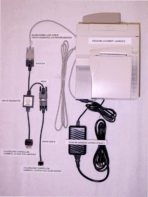
5 10K120 Interface Connections The 10K120 interface consists of electronics enclosed in a small plastic case with two cable assemblies. NCR 2127 register connection The connector 11 on the 10K120 interface single cable assembly plugs into a mating connector on NCR Connect to any of the six available mating sockets on the back panel of the register. See the attached 2127 Register Back View picture. Axiohm printer connection Screw the DB9-M connector on the 10K120 Y or dual cable assembly to the mating DB9-F connector on the supplied Axiohm printer cable. 12 Securely attach the DB9-F connector on the free end of the Axiohm cable to the printer s communications connector. See Axiohm s printer Setup or Owner s Guide. If the Axiohm cable is not available, a cable wired as below will work. 13 Cable 10K120 interface to Axiohm printer DB-9 Receptacle DB-9 Receptacle (female) (female) Pin No. Pin No. 1 & & N.C. N.C. 9 Shell Shell N.C. = No Connection 11 A Compu-shield, Series 31, 15 position plug is on the 10K120 interface single cable assembly. 12 Only one of the connectors, a DB9-M on this cable assembly will mate with the Axiohm cable. Axiohm cable P/N: This is the typical pin-out of a standard null modem cable sold at computer stores. 5
6 Optional MICR connection Connect the Wrenchman 10K96 MICR cable DB9-M connector to the DB9-F connector on the 10K120 Y or dual cable assembly. 14 Connect the other end of the 10K96 cable, a JAE dual row 14 position connector, to the mating connector on the 2127 register that the Welch Allyn MICR reader was using. If MICR was not in use, connect the 10K96 cable to either mating 14 position connector on the 2127 register s OCRS 1 board. See the attached photographs for illustrations of the proper connections to the 10K120 interface and the 2127 register. Setup the 2127 register to support the 10K120 interface Several of the 2127 configuration parameters and Machine Definition Codes must be set to specific values for the 10K120 interface to operate properly. The user should possess an understanding of the procedures to configure the 2127 register. The 2127 manuals, "Action Code Entries", "Parameter Entry", and "Machine Definition Codes" provide information to set 2127 register configuration parameters and describes their function. All numeric values are entered with the number keys for the steps below. Set the 2127 register to use a multifunction printer. Place the keylock in the Super position and hold down the P1 key 15 during power-up of the 2127 register. Type 2127 when prompted for the Access Number and press the Enter key. Type 3 to access Menu Data Type 2 to access the Peripheral Menu Scroll to menu items by pressing the P1 key. Set printer 1 to a "YES" and printers 2 and 3 to "NO" using the P2 key 16. Press the P3 key 17 to exit the Peripheral Menu. 14 The 10K96 cable will mate with only one of the connectors on the assembly. 15 The P1 key is the bottom key in the column of keys to the right of the numeric keypad. 16 The P2 key is the bottom key in the column of keys to the left of the numeric keypad. 6
7 Reset the 2127 register by pressing the "1" key twice. The display will show a line of "D"s with indicators. Changing Machine Definition Code Values Log out all cashiers. Turn the keylock to the "Prog" position. Enter your Secret Number when prompted, followed by the P2 key. At the Enter Program Number prompt, enter 1 and press the P1 key. Enter 89 when prompted for the Report or Address of the Machine Definition Code, followed by the P2 key. Changing the value for address 89 permits zero price PLU s required for configuring the 10K120 interface. Restore this setting to the original value after the 10K120 interface is configured by following the procedure in this section. Enter the value for the corresponding displayed address, given in the table below, followed by the P1 key. The address is automatically incremented. Press the P2 key several times to increment the address to 103. Follow the procedure in the step above to set the values for the addresses in the table below. After entering the new value for the addresses below, press the P1 key to finalize. The 2127 will return to the Enter Program Number prompt. The Machine Definition Codes and Values Machine Definition Code (Address) Value 89 xx1x xx xxx0 x = the value s digit remains the same, as shown on the display for the corresponding address. 17 The P3 key is directly to the left of the 7 key on the numeric keypad. 7
8 Adjust Receipt Format Changing Program 18 values will adjust the 2127 register receipt formatting options to match those needed by the Axiohm printer for proper printing. There are many settings in the 2127 register that can affect receipt appearance and print positioning. They allow the receipt appearance to be tailored to individual preferences. See the three 2127 register manuals mentioned above for more detail on receipt customization. At the Enter Program Number prompt, enter 18 and press the P1 key. Enter a 1 when prompted for the Report or Address, followed by the P2 key. Enter the value for Program 18 addresses in the table below, followed by the P1 key. The program address will increment by one. Repeat the above step until all values in the table below are entered. After all 18 values have been entered, press the P1 Key. The 2127 register will return to the Enter Program Number prompt. Program 18 Addresses and Values Address Value * 18 0 * Negative values are entered by pressing the P4 key before entering the value. The P4 key is located to the right of the 9 key on the numeric key pad. 8
9 Customize the 10K120 Interface The 10K120 interface is customized with special PLU items. The items are entered into the 2127 using a PLU maintenance file. There are two sets of maintenance files, one set for those 2127 systems set up for 20 character PLU descriptors and one set for those 2127 systems set up for 12 to 19 character PLU descriptors. Use only the set that matches your systems PLU descriptor length. The procedure to install either set is the same. The 2127 Add and Delete maintenance files along with the 10K120 interface PLU Configuration scan tags are available online at These PLU item UPC numbers were reserved by Wrenchman, Inc. from the Uniform Code Council and will never appear on any item in a store. If not already received on floppy disks, copy and unzip the add and delete PLU maintenance files onto separate PC formatted diskettes. Add Procedure Place the add disk into the drive on the 2127 register and turn the keylock to the "Super" position. Enter your Supervisor Number followed by the Enter key. At the Enter Action Code prompt enter 65 Enter file number 1 and press the Enter key. Enter selection code 1 and press the Enter key twice. At the Enter Action Code prompt enter 56. Enter file number 1 and press the Enter key. Enter device 1 followed by the Enter key. Press the Enter key again. The disk drive should go active and load the file into the Enter 60 when prompted for an action code. Enter a 1 for the file number and press the Enter key. Enter a 1 for the selection code followed by the Enter key. 9
10 Press the Enter key again. The 2127 should indicate MMM communications and the printer should print a message showing "27 applied 0 failed". Create Department 100 If Dept Not Found or a related message appeared when the last step above was performed or when the configuration labels are entered in the next section, then Department 100 will have to be temporarily created. Follow the next steps to do this: At the Enter Action Code prompt, enter 113. Enter 100 when prompted for the Department Number Press the Enter key twice to finalize the setting. A report should print indicating that a department was created. Delete Procedure The procedure to delete these PLU items from the 2127 follows the same procedure except the delete floppy is used instead of the add floppy. MICR Feature Option If the MICR feature is to be used, information about the MICR user exit configuration will need to be known before setting the 10K120 interface options. At the Enter Action Code prompt, enter 260. Scroll to address 14 by pressing the P1 key. Note the value of the first digit in the four digit number shown. If the first digit is 0, use the Format Dumac Short tag for the 10K120 configuration. If the first digit is 1, use the Format Dumac Long tag for the 10K120 configuration. Press the P2 key to exit Action Code 260 Turn the keylock back to the Reg position and log in a cashier allowing transaction items to be entered. 10
11 Set the 10K120 Interface Options See the options in the section below. The 10K120 options can now be set by scanning the supplied bar codes. If the 2127 register does not have a scanner, manually enter the bar code PLU numbers via the keyboard. Configure and Customize the 10K120 Interface There are 27 option and command items that can be set or controlled. See the following table. The normal procedures to ring up an item also apply to these configuration items. The configuration items are zero priced, so store totals will not be altered. Scanning a tag or entering the respective UPC item number will cause the 10K120 interface to perform the indicated action. The first five and last two configuration items in the table below are action items and do not set a configuration parameter. They perform the indicated action immediately. The remaining items set configuration parameters. They require the Save Configuration Tag to be entered directly after entering the configuration item tag(s). The Save Configuration Tag applies to items 106 through 119 in the Configuration Item Tag Table. The numbers are the last three digits of the item PLU number. If the save configuration tag is not used, the entered configuration parameter(s) will be valid only until the next power cycle at which point the cable will revert to the last saved settings. 11
12 10K120 Interface Configuration Item Tag Table Item PLU No. Description Print Config Report Prints a receipt with the current 10K120 interface saved settings.. Print EJ Report Prints a receipt with the electronic journal total capacity and the amount of that capacity that is used. Print EJ Data Prints the contents of the electronic journal and leaves the journal data intact. Print and Erase EJ Prints the contents of the electronic journal and then erase the journal data. Erase EJ Data This tag will erase the contents of the electronic journal without printing it. Once the data is erased, there is no way to recover it. EJ Data Storage ON Enables the electronic journal function. EJ data Storage OFF Disables the electronic journal function. J View Key ON Enables the journal view feature. J View Key OFF Disables the journal view feature. S Key Erase ON Enables the printing and erasing of journal data with the supervisor key. S Key Erase off Disables the printing and erasing of journal data with the supervisor key. P Key Erase ON Enables the printing and erasing of journal data with the programmers key. P Key Erase OFF Disables the printing and erasing of journal data with the programmers key. MICR Reader ON Enables the MICR functionality. This function also requires the Dumac MICR user exit be installed and configured for MICR to operate correctly. MICR Reader OFF Disables MICR functionality. Format Dumac Long Adjusts the MICR data sent to the register to match the Dumac user exit long format setting. Format Dumac Short Adjusts the MICR data sent to the register to match the Dumac user exit short format setting. Power up Message ON Enables the 10K85 firmware information printout when the 2127 register is powered on, the cable is inserted into a powered 2127 register, or when the printer power is cycled. 12
13 10K120 Interface Configuration Item Tag Table Continued Item PLU No. Description Power up Message OFF Disables the 10K120 firmware information printout when the 2127 register is powered on, the cable is inserted into a powered 2127 register, or when the printer power is cycled. Print Diagnostics Prints the Axiohm configuration page that shows the settings of the Axiohm printer. Load Configuration Loads the configuration values stored in the cable and activates them. Quickset Defaults Sets all the configuration parameters to their default settings. These settings are: Electronic Journal Disabled Power-up Report Enabled MICR Reader Disabled Quickset Sets all the configuration parameters to values for electronic journal but not MICR. These settings are: Electronic Journal Enabled S Key Journal Erase Disabled P Key Journal Erase Enabled Journal Report Key Enabled Power-up Report Enabled MICR Reader Disabled Quickset Sets all the configuration parameters to values for MICR but not electronic journal. These settings are: Electronic Journal Disabled Power-up Report Enabled MICR Reader Enabled MICR Data Format Long Quickset Sets all the configuration parameters to values for MICR and electronic journal. These settings are: Electronic Journal Enabled S Key Journal Erase Disabled P Key Journal Erase Enabled Journal Report Key Enabled Power-up Report Enabled MICR Reader Enabled MICR Data Format Long Save Configuration Saves all the currently set configuration parameters in permanent memory and resets the cable The Save Configuration Tag applies to configuration items 106 through 119 in the Configuration Item Tag Table. The numbers are the last three digits of the item. 13
14 10K120 Interface Configuration Item Tag Table Continued Item PLU No. Description View Journal Prints out the last transactions journal data. Each scan will print out one transaction previous to the last journal transaction printed. Electronic Journal Operation Print a Electronic Journal capacity report Scan or enter the PLU number of the "Print EJ Report" configuration tag. The EJ report will also print out at power-on and whenever the new settings are stored in the 10K120 interface. Print recent Electronic Journal transaction data If enabled via the J View Key ON function, make sure that the keylock is in the Reg position and press the journal feed key. The printer will print out a copy of the electronic journal data of the last transaction. If more data is needed, each press of the journal feed key will move back one transaction in the journal storage from the last journal transaction printed and print that transaction. To finalize the journal view printout, the receipt feed key can be pressed. Print and erase Journal data If enabled via the "S Key Erase ON" function, turn the keylock to the "Super" position and press the journal feed key. If set via the "P Key Erase ON" function, turn the keylock to the "Prog" position and press the journal feed key. Scan the "Print and Erase EJ" tag or enter the respective PLU number. If the above procedures do not work, verify that the associated function is enabled by looking at the report produced from scanning the "Print Config Report" tag or entering the associated PLU number. Erase the Journal data Scan the "Erase EJ Data" tag or enter the associated PLU number. 14
15 Print the Journal data without erasing Scan the "Print EJ Data" tag or enter the associated PLU number Read MICR data from a check Place the check in the printer and press the "Clear" key on the keyboard when the "Enter Acct. #" shows after ringing a transaction with a check tender. Electronic Journal Maintenance Printing The 10K120 interface will post a message when it s EJ capacity is full. Journal data will be lost if the Journal is not serviced at this time. If using the EJ memory in the A760 printer, it will beep when the EJ capacity is full and the EJ data is no longer being stored in the printer. It is recommended that the amount of EJ data in the 10K120 interface or in the printer be monitored on a regular basis so it doesn't reach capacity and lose EJ data. Printing the EJ data on a regular basis will lessen the time that the register is unavailable, due to printing large amounts of EJ data. Security Varying security levels to the EJ data can be accomplished in several ways. This permits different security configurations on each register. Disabling the configuration PLU's that erase or print and erase EJ from the PLU database or controlling possession of the configuration tags will prevent any cashier without a Supervisor or Program key from erasing the EJ data. Disabling the Supervisor key function with the S Key Erase OFF configuration tag will only allow someone with a program key (generally unavailable to anyone except management and technical personel) to erase EJ data. FAQ What if the Printer doesn't print at all or a W5244 or W5245 error shows on the register? 15
16 Check that the printer is powered. A green light, located on the top of the printer should be ON. Verify that the printer configuration settings are as outlined in the Setup of the Axiohm printer section above. Check that the Axiohm cable or compatible RS232 null modem cable is connected between the printer and the 10K120 interface. Check that the 10K120 interface is securely plugged into one of the mating ports on the back of the 2127 register. It should be latched into the receptacle connector. What if the printer line spacing, knife cut, or other print formatting is off? Verify the Machine Definition Codes and Program 18 settings are as outlined in the sections above. There are many settings in the 2127 register that can affect receipt appearance and print positioning and can be tailored to individual preferences. See the three 2127 manuals mentioned above for more detail on the possible customization that can be performed to alter the appearance of the receipt. What if MICR does not operate? Check that the 10K96 cable is connected to the 10K120 interface and is in the correct port on the 2127register. Try the other RS232 port on the 2127 OCRS board if the first is nonfunctional. Check the 10K120 MICR reader setting to verify that it is enabled and the Dumac Format setting is properly set for your system configuration. Contact Dumac at if you have questions concerning MICR settings on the 2127 register. What if the EJ function appears not to operate? If using an Axiohm A760 printer to store EJ data, verify that the printer has the firmware version, as shown on the A760 Diagnostic Form above, or newer. Check that the 10K120 EJ Data Storage setting is enabled and that the desired access method for printing and erasing the EJ data is enabled. 16
17 Verify that the memory setting for Flash Journal Size in the printer is set to a value other than 0. What if there is too much paper on the roll when the paper empty warning is issued? See the Axiohm printer Owners Guide or contact Axiohm for instructions on adjustment. 17
18 18

19 2127 Register Back View 19
Installation and Setup Guide
 Wrenchman, Inc. 10K122 Interface for 2127 POS Printer Replacement Installation and Setup Guide October 11, 2004 1 Introduction The Wrenchman 10K122 interface enables the use of an IBM 4610 thermal printer
RKAT Audit Trail Module RK-LINK TM Software For the Radio Key 600 Series
 RKAT Audit Trail Module RK-LINK TM Software For the Radio Key 600 Series INSTALLATION & OPERATING GUIDE Rev. B P/N 3321515 www.securakeystore.com (800) 878-7829 sales@securakeystore.com COPYRIGHT 2001
Programming Guide. HP Engage One Serial USB and Column Thermal Printers
 Programming Guide HP Engage One Serial USB and Column Thermal Printers Copyright 2017, 2018 HP Development Company, L.P. The information contained herein is subject to change without notice. The only warranties
NCR 7167 Two Station POS Printer Release 2.0. Ownerʹs Manual
 NCR 7167 owners Manual NCR 7167 Two Station POS Printer Release 2.0 Ownerʹs Manual B005-000-1406 Revision E 7167 Owner s Manual Contents Contents Quick Reference... v How to Use this Book... vi Who Should
Updating Reader Firmware
 SWH-xxxx Readers Updating Reader Firmware Version C0 Document Part Number UM-096 July 2012 OVERVIEW This document describes how to download new firmware to Software House SWH-4xxx readers. The procedure
medtester 5000C Automated Biomedical Equipment Test System
 medtester 5000C Automated Biomedical Equipment Test System Field Upgrade Installation Instructions PN 2245628 April 2005 2005 Fluke Corporation, All rights reserved. Printed in USA All product names are
Product Update. Overview. Table of Contents
 Product Update Overview This Product Update explains the changes to the products listed below. Microline 320/321 Turbo Microline 320/321 Turbo / n Microline 390/391 Turbo Microline 390/391 Turbo / n Microline
FASTMARK 4600 PLUS CONTROL PANEL OPERATION. Front Panel
 FASTMARK 4600 PLUS CONTROL PANEL OPERATION Front Panel The front panel includes - LCD display - 3 LED status indicators (READY, MEDIA and RIBBON) - 3 control buttons (FEED, PAUSE and CANCEL) LCD display
DUCM Hardware. Niobrara Research & Development Corporation P.O. Box 3418 Joplin, MO USA
 DUCM Hardware Manual DUCM Hardware Installation Manual This manual covers the DUCM hardware features and installation procedures. Effective: May 29, 2015 Niobrara Research & Development Corporation P.O.
Intelligent Devices IDI 1100 Series Technical Manual
 Intelligent Devices IDI 1100 Series 4411 Suwanee Dam Road, Suite 510 Suwanee, GA 30024 T: (770) 831-3370 support@intelligentdevicesinc.com Copyright 2011, Intelligent Devices, Inc. All Rights Reserved
Installation & Operation. P/N Edition 3 November EasyCoder C4 Keyboard Display Unit
 Installation & Operation P/N 1-960416-02 Edition 3 November 2001 EasyCoder C4 1. Keyboard/Display Unit Description The (KDU) is a terminal unit that provides Intermec EasyCoder C4 with a stand-alone capacity.
Programming Guide. HP Value Serial/USB Receipt Printer II
 Programming Guide HP Value Serial/USB Receipt Printer II Copyright 2016 HP Development Company, L.P. The information contained herein is subject to change without notice. The only warranties for HP products
Liquid Volume Dispenser
 Liquid Volume Dispenser Table of Contents 1. Introduction 3 2. Installation 3 3. Volume Accuracy 3 4. Operator Controls 4 5. Operating States 4 5.1 Ready 4 5.2 Dispensing 5 5.3 Manual Dispensing 5 5.4
Installation Instructions
 Installation Instructions Windows 7/XP Printer Driver USB (USB Printer Class only) / LAN Overview: The Windows Printer Driver for Windows 7 and XP Pro requires a new interface type, which is a true USB
Understanding printer messages
 The operator panel displays messages describing the current state of the printer and indicates possible printer problems you must resolve. This topic provides a list of all printer messages, explains what
Models: TD3000 Series. Table Displays. 2 by 20 character display USER MANUAL
 Models: TD3000 Series Table Displays 2 by 20 character display USER MANUAL i NOTICE The manufacturer of the POS table display makes no representations or warranties, either expressed or implied, by or
Summary of TTP 2100 Firmware Version 4.02 Changes
 Kiosk TTP 2100 Firmware Version 4.02 Summary of TTP 2100 Firmware Version 4.02 Changes Release date: 28 June 2014 Supported Printer Firmware This firmware release includes the features of the previous
Programming Guide. A798II Thermal Receipt Printer
 A798II Thermal Receipt Printer Programming Guide Made under one or more of the following U.S. patents: 4886381, 5579043, 5613787, 5651624, 5713678, 5752779, 5789916, 5800080, 5879090, 5887999, 5975776,
B Revision C November, NCR 7167 Two Station POS Printer Release 1.0 Owner's Manual
 B005-000-1406 Revision C November, 2002 NCR 7167 Two Station POS Printer Release 1.0 Owner's Manual The product described in this book is a licensed product of NCR Corporation. NCR is the registered trademark
Summary of TTP 2000 Firmware Version 4.01 Changes
 Kiosk TTP 2000 Firmware Version 4.01 Summary of TTP 2000 Firmware Version 4.01 Changes Release date: 29 July 2014 Supported Printer Firmware This firmware release includes the features of the previous
Model: KB1700. Programmable Keypad. 17 Programmable Keys USER MANUAL
 Model: KB1700 Programmable Keypad 17 Programmable Keys USER MANUAL NOTICE The manufacturer of the POS programmable keypad makes no representations or warranties, either expressed or implied, by or with
AccuPOS Hardware Setup Guide TABLE OF CONTENTS
 AccuPOS Hardware Setup Guide TABLE OF CONTENTS 1. Receipt Printer (TSP 100) a. Unpacking b. Parts Identification c. Hardware setup and Cable connection d. Software Setup e. Configuring Receipt Printer
User Guide. A760 Two-Color Thermal/Impact Hybrid Printer. New TPG, Inc. LogoEZ colorization utility information included.
 A760 Two-Color Thermal/Impact Hybrid Printer User Guide New TPG, Inc. LogoEZ colorization utility information included. Made under one or more of the following U.S. patents: 4886381, 5579043, 5613787,
Industrial 24-Port 10/100/1000Mbps Managed Gigabit. Switch (-40~75 degrees C) with 4 Shared SFP Ports IGSW-24040T. Quick Installation Guide
 with 4 Shared SFP Ports IGSW-24040T. Quick Installation Guide") Industrial 24-Port 10/100/1000Mbps Managed Gigabit Switch (-40~75 degrees C) with 4 Shared SFP Ports IGSW-24040T Quick Installation Guide Table of Contents 1. Package Contents... 3 2. Requirements... 4
Industrial 24-Port 10/100/1000Mbps Managed Gigabit Switch (-40~75 degrees C) with 4 Shared SFP Ports IGSW-24040T Quick Installation Guide Table of Contents 1. Package Contents... 3 2. Requirements... 4
PROGRAMMING AND USE INSTRUCTIONS FOR THE OVATION SYSTEM
 Doc. 6001012 Rev B PROGRAMMING AND USE INSTRUCTIONS FOR THE OVATION SYSTEM ALPHA COMMUNICATIONS 42 Central Drive Farmingdale NY 11735-1202 Phone: 631-777-5500 - Fax: 631-777-5599 IMPORTANT NOTICE If the
Industrial L2+ Multi-Port Full Gigabit. Managed Ethernet Switch IGS-10020MT / IGS-10020PT/HPT / IGS-10080MFT IGS-12040MT / IGS-20040MT / IGS-20160HPT
 Industrial L2+ Multi-Port Full Gigabit Managed Ethernet Switch IGS-10020MT / IGS-10020PT/HPT / IGS-10080MFT IGS-12040MT / IGS-20040MT / IGS-20160HPT Quick Installation Guide Table of Contents 1. Package
Installation / Set-up of Autoread Camera System to DS1000/DS1200 Inserters
 Installation / Set-up of Autoread Camera System to DS1000/DS1200 Inserters Written By: Colin Langridge Issue: Draft Date: 03 rd July 2008 1 Date: 29 th July 2008 Page 1 of 25 Installation Instructions
Quick Installation Guide Direct and Transfer Thermal Printer
 Quick Installation Guide Direct and Transfer Thermal Printer Overview The enclosed printer is currently comprised of two models: 203dpi (dots per inch) model 300dpi (dots per inch) model Unpacking 1. Remove
ADVANCED DRIVER PROGRAMMING. EVERset User Manual
 ADVANCED DRIVER PROGRAMMING EVERset User Manual User Manual Rev1.4 10/03/2018 Table of Contents 1. Introduction... 2 2. Computer System Requirements... 2 3. Definitions System Definitions... 3 Setting
Installation and Programming Manual
 IBSM Manual IBSM Installation and Programming Manual This Manual describes the IBSM InterBus-S Master, its uses and set up. It also describes the use of the IBSM configuration software. Effective: 12 June,
LBI Mobile Communications S825 FLASH PROGRAMMING. Programming Instructions
 LBI-38991 Mobile Communications S825 FLASH PROGRAMMING Programming Instructions TABLE OF CONTENTS INTRODUCTION...3 INSTALLATION...3 REQUIREMENTS...3 MAKING BACKUPS...3 SYSTEM HOOK-UP...4 S825 Control Unit...4
Industrial L2+ Multi-Port Full Gigabit. Managed Ethernet Switch IGS T2S/IGS UP1T2S IGS P2S/IGS P4S/IGS P2T2S
 Industrial L2+ Multi-Port Full Gigabit Managed Ethernet Switch IGS-5225-4T2S/IGS-5225-4UP1T2S IGS-5225-8P2S/IGS-5225-8P4S/IGS-5225-8P2T2S Quick Installation Guide Table of Contents 1. Package Contents...
Auper Electronic Controls Inc. Eclipse 784 B. Quick User Guide
 Auper Electronic Controls Inc Eclipse 784 B Quick User Guide 2 2010 Auper Electronic Controls Inc Edition E784BE 1.2 INSTALLATION 1. Mount your Eclipse system, away from areas where liquor spills could
MSOC Communication Commonality with DPU/TPU/GPU 2000R Protective Relays
 ABB Application Note MSOC AN-64A-00 Substation Automation and Protection Division MSOC Communication Commonality with DPU/TPU/GPU 2000R Protective Relays Introduction There seems to be some confusion with
Digital Bench Scale. Revision 1.2 September 14, 2000 Contents subject to change without notice.
 Digital Bench Scale Revision 1.2 September 14, 2000 Contents subject to change without notice. Salter Brecknell Weighing Products 1000 Armstrong Drive Fairmont, MN 56031 Tel (800) 637-0529 Tel (507) 238-8702
Programming Guide. A799II Two-Color Thermal Receipt Printer. Includes LogoEZ colorization utility and Receiptware marketing software information.
 A799II Two-Color Thermal Receipt Printer Programming Guide Includes LogoEZ colorization utility and Receiptware marketing software information. Made under one or more of the following U.S. patents: 4886381,
Initial Configuration on ML-Series Card
 CHAPTER 3 This chapter describes the initial configuration of the ML-Series card and contains the following major sections: Hardware Installation, page 3-1 Cisco IOS on the ML-Series Card, page 3-2 Startup
IBM SureMark Printers
 Fast, high-quality thermal receipt printing plus advanced electronic check processing IBM SureMark Printers Dual-station models Highlights Thermal printing delivers excellent speed and image quality Single-pass,
Installation / Set-up of WJPro / IJ-15K Frankers to DS1000 / DS 1200 Inserters
 Installation / Set-up of WJPro / IJ-15K Frankers to DS1000 / DS 1200 Inserters Written By: Colin Langridge Issue: Draft Date: 08 th May 2008 Issue: 1 Date: 23 rd May 2008 Issue: 2 Date: 06 th June 2008
Sentinel SmartTouch Instruction Manual
 Sentinel SmartTouch Instruction Manual 1. Introduction.. 2 2. Installing the Software... 2-6 3. Using Admin to setup SmartTouch.. 7-25 4. Using SmartTouch 26-28 5. Main Flags. 29-30 6. SmartTouch Upgrade
ACS-LCD-128x64. LCD Graphic Display Terminal. General Description. Features. Typical Applications. Specifications. 22-Feb-08
 6 2 3 3 E. S a w g ra s s R d S a ra s o ta, F L. 3 4 2 4 0 (9 4 1 )3 7 7-5 7 7 5 F A X(9 4 1 )3 7 8-4 2 2 6 www.acscontrol.com 22-Feb-08 ACS-LCD-128x64 LCD Graphic Display Terminal General Description
24-Port 100/1000X SFP + 4-Port 10G SFP+ Managed. Metro Ethernet Switch MGSW-28240F. Quick Installation Guide
 24-Port 100/1000X SFP + 4-Port 10G SFP+ Managed Metro Ethernet Switch MGSW-28240F Quick Installation Guide Table of Contents 1. Package Contents... 3 2. Requirements... 4 3. Wiring DC Power Inputs... 5
CncGcoder Models HD & HDx Manual
 CncGcoder Models HD & HDx Manual Table of Contents WELCOME... 3 IN THE BOX... 4 Optional Accessories...4 HANDHELD OVERVIEW... 5 Overview...5 Charging the Battery...6 Turning On and Off...6 Plugging in
IMPORTANT! GE Caddx panels cannot support PIN codes then end in zero over RS-232. See Common Mistakes for more information.
 Manufacturer: GE NetworX Integration Note Model Number(s): NX-4,6,8 Core Module Version: Document Revision Date: 01/09/2016 OVERVIEW AND SUPPORTED FEATURES The NetworX NX-4,6,8 security panels integrate
XS US/Mexico Software Release Notes
 Triton Systems of Delaware, INC. XS 2.4.0 US/Mexico Software Release Notes Affected products RL1600, RL2000, RL5000, FT5000, RT2000 December 3, 2009 Version 1.6 Triton Systems of Delaware, Inc. 21405 B
CA400S INSTALLATION INSTRUCTIONS
 Cumana Ltd., Pines Trading Estate, Broad Street, Guildford, Surrey, GU3 3BH. Tel: (0483) 503121 Telex: 859380 Fax No. 503326 CA400S INSTALLATION INSTRUCTIONS Introduction This document details the installation
Instructions for Installing FlashUpdate and Downloading Updates for Super Buddy Satellite Meter
 Instructions for Installing FlashUpdate and Downloading Updates for Super Buddy Satellite Meter Updates to the Field Guide and to the instrument firmware are available from the Applied Instruments website.
Phoenix Printer Tools Software
 Phoenix Printer Tools Software Installation and Operation System Requires Supported Operating System Windows Vista Windows 7 Windows 8.1 Windows 10 At least one USB 2.0 port (or newer) 512MB RAM 15MB Hard
Wireless laser barcode collector User's Guide DC8050= wireless barcode collector scanner & wireless data collector
 Wireless laser barcode collector User's Guide DC8050= wireless barcode collector scanner & wireless data collector First, product introduction 1, Functional characteristics Welcome to this new concept
NTI. KEEMUX Series. KEEMUX-P2 (2-Port PS/2 KVM Switch) INSTALLATION / USER GUIDE R NETWORK TECHNOLOGIES INCORPORATED
 INSTALLATION / USER GUIDE R NETWORK TECHNOLOGIES INCORPORATED") NTI R NETWORK TECHNOLOGIES INCORPORATED 1275 Danner Dr Aurora, OH 44202 Tel:330-562-7070 Fax:330-562-1999 www.nti1.com KEEMUX-P2 (2-Port PS/2 KVM Switch) INSTALLATION / USER GUIDE KEEMUX Series MAN049
NTI R NETWORK TECHNOLOGIES INCORPORATED 1275 Danner Dr Aurora, OH 44202 Tel:330-562-7070 Fax:330-562-1999 www.nti1.com KEEMUX-P2 (2-Port PS/2 KVM Switch) INSTALLATION / USER GUIDE KEEMUX Series MAN049
CR35(B) CASH REGISTER QUICK START MANUAL
 CASH REGISTER QUICK START MANUAL") CR35(B) CASH REGISTER QUICK START MANUAL 1 KEYBOARD 1.1 Keyboard Layout 1.2 Basic Key Functions -Use to feed the paper through the receipt printer. -Clerk login or change operation mode. -Use with a numerical
CR35(B) CASH REGISTER QUICK START MANUAL 1 KEYBOARD 1.1 Keyboard Layout 1.2 Basic Key Functions -Use to feed the paper through the receipt printer. -Clerk login or change operation mode. -Use with a numerical
Addmaster Corporation
 IJ-1000 Ink-Jet Validation Printer Specification Addmaster Corporation Address: 225 East Huntington Drive Monrovia, CA 91016 Web: www.addmaster.com Phone: (626) 358-2395 FAX: (626) 358-2784 Document: ij1w.doc
AM3517 experimenter Kit. QuickStart Guide O
 AM3517 :: :: O M QuickStart Guide www.logicpd.comz O QuickStart Guide We fast forward the evolution of new products. Table of Contents 1 Introduction 4 1.1 Scope of Document 4 1.2 Zoom AM3517 Contents
TALS 2. Torque Activated Logging System. Operating Instructions
 TALS 2 Torque Activated Logging System Operating Instructions Contents Page 1. The TALS-2 Primary system 3 Items comprising TALS Core System 2. System Setup 4 3. Connecting The Power 5 4. To learn a new
Industrial 8-Port 10/100/1000T 802.3af/at PoE + 2-Port 100/1000X SFP Managed Switch with Wide Operating Temperature
 Industrial 8-Port 10/100/1000T 802.3af/at PoE + 2-Port 100/1000X SFP Managed Switch with Wide Operating Temperature IGS-10020PT / IGS-10020HPT Quick Installation Guide Version 1.0 Table of Contents 1.
NCR 7197 Thermal Receipt Printer Release 1.0 Owner's Manual
 NCR 7197 Thermal Receipt Printer Release 1.0 Owner's Manual B005-000-1409 Revision C November, 2002 The product described in this book is a licensed product of NCR Corporation. NCR is the registered trademark
Data Broadcast Switch
 Data Broadcast TABLE OF CONTENTS SECTION 1 - DESCRIPTION... SECTION - SPECIFICATIONS... SECTION - INSTALLATION... SECTION - FRONT PANEL CONTROLS AND INDICATORS... SECTION - INTERFACE SIGNALS AND CABLING...
Magnetek Material Handling IMPULSE LINK 4.1 Basic Instruction Manual
 Magnetek Material Handling IMPULSE LINK 4.1 Basic Instruction Manual February 2006 Part Number: 140-10350 Copyright 2006 Magnetek Material Handling 2005 MAGNETEK MATERIAL HANDLING All rights reserved.
CR3000 Copy Reader. Installation Guide
 CR3000 Copy Reader Installation Guide CONTENTS CONTENTS 1 CR3000 Installation Guide 1 What you get: 2 Installation Overview 3 Install the Reader 4 Mount the Reader 4 Connect the Reader Cables 5 Connect
CPM Series. Control Port Manager. User's Guide. Models CPM-1600 and CPM-800
 WTI Part No. 12348 Rev. B CPM Series Control Port Manager Models CPM-1600 and CPM-800 User's Guide 5 Sterling Irvine California 92618 (949) 586-9950 Toll Free: 1-800-854-7226 Fax: (949) 583-9514 http://www.wti.com
5300 Series Printer Users Guide
 5300 Series Printer Users Guide Pertech Resources Inc. November 2005 220321A-01 Disclaimer Information in this document is subject to change without notice. Consult your Pertech sales representative for
Operating Manual. Sigma Counting Scale. CTG-9850 Series (AC Powered) Issue #9 3/ by Fairbanks Scales Inc. All rights reserved
 Issue #9 3/ by Fairbanks Scales Inc. All rights reserved") Operating Manual Sigma Counting Scale CTG-9850 Series (AC Powered) 2004 by Fairbanks Scales Inc. All rights reserved 50165 Issue #9 3/04 Amendment Record Sigma Counting Scale CTG-9850 Series 50165 Manufactured
Operating Manual Sigma Counting Scale CTG-9850 Series (AC Powered) 2004 by Fairbanks Scales Inc. All rights reserved 50165 Issue #9 3/04 Amendment Record Sigma Counting Scale CTG-9850 Series 50165 Manufactured
USER GUIDE. to the CP130. Thermal Printer
 USER GUIDE to the CP130 Thermal Printer Revision: 1.0 Filename: CP130 Users Guide v1 0.doc Date: 29 March 2011 1 TABLE OF CONTENTS 1 Table of Contents... 2 2 Introduction... 3 2.1 Notes on Printer Firmware
RM024 DVK USER GUIDE VERSION 1.2
 USER GUIDE VERSION 1.2 Americas: +1-800-492-2320 Asia: +852-2923-0610 REVISION HISTORY Version Revision Date Change Description Approved By 1.0 20 Dec 2012 Initial Release Chris Downey 1.1 15 Apr 2014
Initial Configuration
 3 CHAPTER This chapter describes the initial configuration of the ML-Series card and contains the following major sections: Hardware Installation, page 3-1 Cisco IOS on the ML-Series Card, page 3-2 Startup
PMEUCM Hardware. Niobrara Research & Development Corporation P.O. Box 3418 Joplin, MO USA
 PMEUCM Hardware Manual PMEUCM Hardware Installation Manual This manual covers the PMEUCM hardware features and installation procedures. Effective: August 10, 2017 Niobrara Research & Development Corporation
MAGUIRE PRODUCTS, INC. 11 Crozerville Road Aston, PA tel: fax:
 MAGUIRE PRODUCTS, INC. 11 Crozerville Road Aston, PA 1914 tel: 61-459-43 fax: 61-459-27 www.maguire.com BAR CODE DOCUMENTATION Communications Between Maguire MLAN equipment and a Bar Code Scanner BAR CODE
CF2SCSI Disk Bridge User Guide
 CF2SCSI Disk Bridge User Guide Overview The CF2SCSI bridge PCB is a general purpose SCSI bridge PCB for a Compact Flash (CF) Card. A regular CF card is plugged into the 3M CF socket at the end of the PCB
MPP6800 series - PANEL MOUNT PRINTERS. Options
 series - PANEL MOUNT PRINTERS Page 1 of 12 MPP6810 MPP6820 MPP6840 Introduction 5-8Vdc, 4A peak 5-8Vdc, 2A peak 10-35Vdc 24Vdc Features Easy load paper feature High resolution thermal printing 5-8Vdc standard,
USER-MANUAL EMIT MINI TIME RECORDER VERSION 3 AND THERMAL PRINTER
 USER-MANUAL EMIT MINI TIME RECORDER VERSION 3 AND THERMAL PRINTER (c) Emit 19.oct 2003, rev 3 Emit AS Tel: 22 91 03 00 Bank: 6011.05.80439 St. Halvards gt. 33 Fax: 22 91 03 01 WEB: www.emit.no 0192 OSLO
Management Security Switch SGSD-1022 / SGSD-1022P SGSW-2840 / SGSW-2840P. Quick Installation Guide
 Management Security Switch SGSD-1022 / SGSD-1022P SGSW-2840 / SGSW-2840P Quick Installation Guide Table of Contents 1. Package Content... 3 2. Requirements... 4 3. Terminal Setup... 5 4. Logon to the Console...
USER MANUAL EMIT MINI TIME RECORDER VERSION 4 AND THERMAL PRINTER
 USER MANUAL EMIT MINI TIME RECORDER VERSION 4 AND THERMAL PRINTER (c) Emit 28.sep 2004, rev 3 Emit AS Tel: +47 22 91 03 00 Bank: 6011.05.80439 St. Halvards gt. 33 Fax: +47 22 91 03 01 WEB: www.emit.no
Card Dispensing/Collecting Machine
 A 1 OF 36 2010. 03. 02. Card Dispensing/Collecting Machine Series. 3,,. http://www.securetech-corp.com E-mail : sales@securetech-corp.com A 2 OF 36 2010. 03. 02. REVISION HISTORY No DATE DESCRIPTION REV
RA Triage Procedure. Product: DM8050 & DM8600 series. 1.0 Useful Components & Accessories
 RA Triage Procedure Product: DM8050 & DM8600 series 1.0 Useful Components & Accessories 1.1 Cognex Single Port AC PoE Injector (Fig. 1) 1.2 USB cable (Fig. 2) 1.3 RS232 cable (Fig. 3) 1.4 WiFi or Bluetooth
Quick Start Installation Guide
 apc/l Quick Start Installation Guide Version A2 Document Part Number UM-201 May 2010 OVERVIEW The apc/l is an intelligent access control and alarm monitoring control panel which serves as a basic building
Longshine Technologie Europe GmbH LCS-MFP101-2 Multifunction Printserver
 Longshine Technologie Europe GmbH LCS-MFP101-2 Multifunction Printserver www.longshine.de TABLE OF CONTENTS COPYRIGHT...2 1. INTRODUCTION...3 PRODUCT OVERVIEW...3 COMPONENTS AND FEATURES...3 HARDWARE INSTALLATION...3
PIcon Console Controller
 Console Controller User Reference Manual 2422 Atlantic Avenue Raleigh, North Carolina 27604 Phone 919 821-1323 Fax 919 821-1325 www.pie-corp.com Copyright 2003 Progressive International Electronics, Inc.
Getting Started with your D3000M Series Module
 Getting Started with your D3000M Series Module This document contains step-by-step instructions to quickly connect and communicate with your D3000M modules. The modules require a one-time configuration
Programmable Keyboard SERIES 8031 S
 Programmable Keyboard SERIES 8031 S Operation Manual Version 1.0 This equipment has been tested and found to comply with the limits for Class A digital device. Pursuant to Part 15 of the FCC Rules. These
Monarch 939i Intelligent Keyboard
 Monarch 939i Intelligent Keyboard TC0939iOI Rev. AF 12/07 2004 Paxar Americas, Inc. a subsidiary of Avery Dennison Corp. All rights reserved. Each product and program carries a respective written warranty,
SB72EX User's Manual
 etburner SB72EX User's Manual Revision: 1.8 October 8, 2009 SB72EX User's Manual, 350030-001 Table of Contents Table of Contents...2 Overview of the SB72EX Dual-port Serial to Ethernet Device... 3 Overview
Select a Data Communication Interface
 Printer Setup and Operation Select a Data Communication Interface Select a Data Communication Interface You may connect your print engine to a computer using one or more of the available connections. The
L2+ Managed Metro Ethernet Switch MGSW / MGSD Series
 L2+ Managed Metro Ethernet Switch MGSW / MGSD Series Quick Installation Guide Table of Contents 1. Package Contents... 3 2. Requirements... 4 3. Wiring DC Power Inputs... 5 4. Terminal Setup... 6 5. Logon
7561-PSD Manual Portable Battery Powered Indicator
 7561-PSD Manual Portable Battery Powered Indicator Lebow Products Inc. 1728 Maplelawn Drive P.O. Box 1089 Troy, Michigan 48084-1089 (800) 803-1164 Phone: (248) 643-0220 FAX: (248) 643-0259 Visit our web
L2/L4 Managed Gigabit Ethernet Switch GS-4210 Ultra PoE Series
 L2/L4 Managed Gigabit Ethernet Switch GS-4210 Ultra PoE Series Quick Installation Guide Table of Contents 1. Introduction... 3 2. Package Contents... 4 3. Requirements... 5 4. Terminal Setup... 6 5. Logon
FERGUSON BEAUREGARD. RTU-5000 Configurator User Manual
 FERGUSON BEAUREGARD RTU-5000 Configurator User Manual FERGUSON BEAUREGARD RTU-5000 Configurator User Manual The Ferguson Beauregard RTU-5000 Configurator program and manuals are Copyright 1997-2004 by
Multi-port Coax + 2-port 10/100/1000T + 2-port. 100/1000X SFP Long Reach PoE over Coaxial. Managed Switch LRP-822CS / LRP-1622CS
 Multi-port Coax + 2-port 10/100/1000T + 2-port 100/1000X SFP Long Reach PoE over Coaxial Managed Switch LRP-822CS / LRP-1622CS Quick Installation Guide Table of Contents 1. Package Contents... 3 2. Requirements...
GENISYS MICROLOK-PLUS TM
 IUNION SWITCH & SIGNAL I [WI A member of the ANSALDO Group 5800 Corporate Drive Pittsburgh, PA 15237 SERVICE MANUAL 6301 -m~m111111m1 1 1 1mm111 II Installation Procedures - Hard and Dual-Floppy Disks
CUSTOM MANUFACTURED IN U.S.A. BY RADIO SHACK, A DIVISION OF TANDY CORPORATION CAT. NO
 CUSTOM MANUFACTURED IN U.S.A. BY RADIO SHACK, A DIVISION OF TANDY CORPORATION CAT. NO. 26-6050 TRS-80 DT-1 OWNER'S MANUAL Contents Introduction 1 1/ Description of the DT-1 3 2/ Setting Up the DT-1 5
Axxis Biometrics LLC. BioAxxis L113 Fingerprint Door Lock Programming Kit
 Axxis Biometrics LLC BioAxxis L113 Fingerprint Door Lock Programming Kit Revision 0.14 Dec 2005 Table of Contents 1. Introduction... 2 Product Overview... 2 Main Features... 2 Packing Lists... 3 2. Operation
Industrial L2/L4 Managed Gigabit Switch. With 4-Port 802.3at PoE+ IGS P4T/IGS P4T2S. Quick Installation Guide
 Industrial L2/L4 Managed Gigabit Switch With 4-Port 802.3at PoE+ IGS-4215-4P4T/IGS-4215-4P4T2S Quick Installation Guide Table of Contents 1. Package Contents... 3 2. Requirements... 4 3. Wiring the Power
Wi-Fi Configuration Guide
 Wi-Fi Configuration Guide NCR RealPOS 7197 Receipt Printer B005-0000-2375 Issue A The product described in this book is a licensed product of NCR Corporation. NCR is a registered trademark of NCR Corporation.
AX3000 Platine Terminal Ethernet TCP/IP
 AX3000 Platine Terminal Ethernet TCP/IP Model 75E Installation Guide January 003 - Ref: I75EE0303-1 Model AX3000/M75E The reproduction of this material, in part or whole, is strictly prohibited. For additional
Product Specification for CANbus to DeviceNet Transducer Gateway
 XG CANbus to DeviceNet Transducer Gateway April, 00 Product Specification for CANbus to DeviceNet Transducer Gateway The XG CANbus to DeviceNet Temposonics Gateway gathers position information from as
User manual. Emit Time Recorder ETR3
 User manual Emit Time Recorder ETR3 (c) Emit 5. Oktober 2006, rev 2 Emit AS Tel: +47 22 91 03 00 Bank: 6011.05.80439 St. Halvards gt. 33 Fax: +47 22 91 03 01 WEB: www.emit.no N-0192 OSLO E-mail: emit@emit.no
ZCRMZNICE01ZEMG Crimzon In-Circuit Emulator
 Quick Start Guide QS006602-0408 Introduction Zilog s ZCRMZNICE01ZEMG Crimzon (ICE), shown in Figure 1, provides Crimzon chip family emulation with a Trace and Event system for program debugging using Zilog
380 / 420 /52xx M Series FEATURE SET-UP MANUAL
 380 / 420 /52xx M Series FEATURE SET-UP MANUAL YCR M Series Page 2 CONTENTS CLERK INTERRUPT... 4 CLERK INTERRUPT BY PUSH BUTTON... 5 CLERK INTERRUPT BY SECRET CODE... 6 GUEST CHECK MANAGEMENT...8 REMOTE
SIMREX Corporation Your Trusted Wireless Solution Provider
 SIMSYNC Instruction Manual Traffic Controller Time/Date Synchronization/Coordination System Firmware Release 2.5h SIMREX MAN.SIMSYNC, Rev 13.0 FEBRUARY 2008 Your Trusted Wireless Solution Provider www.simrex.com
Wrenchman, Inc Old Hwy. # 8 Suite # 122 New Brighton, Minnesota (651)
") Wrenchman, Inc. 1801 Old Hwy. # 8 Suite # 122 New Brighton, Minnesota 55112 (651) 638-9012 468X Interface Cable Specifications The Interface Cable emulates the Async RS-232 logical interface supported
Wrenchman, Inc. 1801 Old Hwy. # 8 Suite # 122 New Brighton, Minnesota 55112 (651) 638-9012 468X Interface Cable Specifications The Interface Cable emulates the Async RS-232 logical interface supported
WiFi to RS-232 adapter user manual
 WiFi to RS-232 adapter user manual WiFi to RS-232 adapter Package Contents: WiFi RS-232 adapter x 1 A4 User manual x 1 Mini USB Cable x 1 White Box Dimension: 11 x 6 x 5 (cm) Total Package Weight: 126