SIMREX Corporation Your Trusted Wireless Solution Provider
|
|
|
- Jack Page
- 6 years ago
- Views:
Transcription


1 SIMSYNC Instruction Manual Traffic Controller Time/Date Synchronization/Coordination System Firmware Release 2.5h SIMREX MAN.SIMSYNC, Rev 13.0 FEBRUARY 2008 Your Trusted Wireless Solution Provider
2
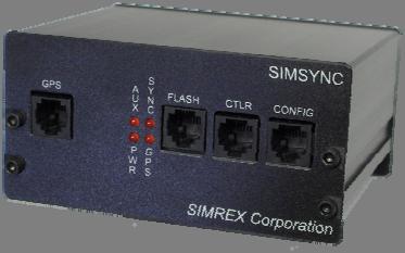
3 Introduction The SimSync is a device used for time synchronization of traffic control devices. It consists of the SimSync controller and a weatherproof/tamperproof GPS receiver. The SimSync controller receives GPS messages from the GPS receiver, reformats the information to your local time zone, automatically adjusting for Daylight Saving Time (DST) and leap years and then sends time information in UTC (or GMT) time to the Traffic Controller at an interval based on your custom settings. There are six (6) connection points on the SimSync unit: 1. POWER (2-pin Phoenix) positive (inside) and negative (outside) for 9-24VDC input. Optional wall mount or desk mount power adapter is available. 2. RELAY (3-pin Phoenix) normally open, normally closed and common connection points. 3. GPS (6-pin RJ-12) proprietary connection for SIMREX SIMGPS1-HD-RJ12-5V GPS antenna. 4. CONTROLLER (6-pin RJ-12) - connection to Traffic Controller for normal operation using proprietary controller cable (supplied). 5. PROGRAM/MONITOR (6-pin RJ-12) multi function a) programming of SimSync controller using proprietary DB9M to RJ-12 cable (See SimSync Commands below). b) monitoring of GPS message strings using proprietary DB9M to RJ-12 cable.. 6. FLASH UPDATE (6-pin RJ-12) firmware upgrade using proprietary flash upgrade cable (optional). 1 of 23
4 A drilling template is provided for accurate installation of the GPS antenna enclosure to the top of the traffic control box or applicable enclosure. Apply RTV adhesive (provided) between antenna enclosure and traffic control box to prevent leakage. Mounting brackets for the SimSync are also available. After the mechanical installation is complete, make the following connections: 1. Plug the GPS receiver RJ-12 connector into the SimSync controller. 2. Make applicable relay connections, if needed 3. Install controller cable between SimSync RJ-12 and Traffic Controller (see connection list below) 4. Install power connection. LED Indicators PWR LED GPS LED Indicates voltage at the output of the internal 5V regulator. This power is used for the GPS as well as the SimSync controller. Indicates the presence of GPS data sent to the SimSync controller. A flash occurs every time there is a message. This should be once per second. A short flash of 100 ms indicates data that does not have a valid time and or date and is thus not used by the SimSync to synchronize its own Real Time Clock. A long flash of 500 ms (50% duty cycle on the LED as it is flashing once per sec) indicates that valid time and date are sent from GPS to SimSync. 2 of 23
5 SYNC LED Indicates that data is sent from SimSync to Traffic Controller. If the unit has been just powered up, no message is sent to the Traffic Controller until valid data (time/date) is sent from the GPS to the SimSync Controller so that the SimSync real time clock may be initialized. Once the SimSync real time clock has been initialized, the SimSync will continue to send date and time to the Controller even if it loses contact with the GPS or if the GPS produces invalid data (signal blockage). During periods of lost GPS signal or invalid data, the SimSync will coast on its own internal clock and update the controller. NOTE: See the command section for J - Inv Relay for additional information on this LED indicator. The relay on SimSync units will be transitioned when a message is sent to the Traffic Controller. This click is audible. Update Rate For testing purposes, any update rate may be used so that correction of a controller may be quickly seen. Five (5) to thirty (30) seconds is common for this. In a permanent installation, it is recommended that an update of only once per day is used. A common practice is to use 4:00 AM. Startup The SimSync controller will produce and send valid time/date messages to the Traffic Controller in less than 5 minutes if it is powered up in an area that has a good view of the sky AND if it has been powered up with valid GPS data in the 3 of 23
6 last 1 to 2 weeks. If the SimSync controller has been powered down for more than 1 to 2 weeks, it can take as long as 12.5 minutes to produce valid GPS time and date. The 12.5 minute delay is not a limitation of the SimSync, but rather the GPS ALMANAC message structure that is broadcast by GPS satellites every 12.5 minutes. Configuration Any terminal program can be used to configure the SimSync controller. Windows HyperTerminal, for example, is a common choice. The configuration port settings on the SimSync default to 9,600 baud, 8 data bits, no parity, 1 stop bit, or more commonly seen as 9600,8,N,1. After setting up the terminal program, apply power to the SimSync. The LED on the front panel labeled PWR indicates that DC power is successfully making it to the controller. There is an LED marked GPS that flashes every time a GPS string is received from the GPS receiver, so you should see this flashing at a 1 second interval. The LED called out as SYNC turn s on when a time update is being sent to the Traffic Controller. Version 2.5 of the SimSync firmware replaces the bare terminal screen configuration with a menu. With a terminal program running and the CONFIG port connected, power up the unit. If the terminal program is set up correctly, you will see the screen below. 4 of 23


7 This screen lists the product name, interval firmware version, the unit serial number, and also reports if a boot-up option is selected. If you need to update the firmware for any reason, ALWAYS verify the unit serial number from this screen, as field updates for Simrex products are serial number specific. The configuration is password protected. Press Enter to stop data from being displayed on the screen and the Password> prompt will appear. If an incorrect password or no password is entered and Enter is hit, the screen will revert back to the data display mode. The default password is 9999, press Enter. It is recommended that the password is changed from the default to a custom password of your choice. When setting a new password, it must be between 5 and 20, and only alpha-numeric characters are accepted, 0 through 9 and a through z. Additionally, the password is case sensitive. 5 of 23
 Some help is available at the main menu screen. Enter a?")
8 After successfully entering the password, the main menu screen is shown on the terminal screen. (Note: Menu selections above that a > following its name indicates that a sub-menu will be shown when this selection is made.) Some help is available at the main menu screen. Enter a? followed by the menu letter for a brief description of that particular setting. BAUD RATES Valid baud rates are 1200, 2400, 4800, 19200, 38400, and Use A, B & C for setting the baud rate for each serial port. The terminal screen above shows the default baud rate settings. To modify them, simply enter the corresponding letter choice, the press enter. Each time A, B, or C is entered, that baud rate will increase to the next speed until it rolls over back to 1200 from of 23
9 SimSync SETTINGS The next section deals with configuration of the time update message. D Message Format Type d or D, and press return. This will bring up the Message Format sub-menu. If NTCIP/PMPP Compliant is chosen, after making that choice, you will be given the opportunity to change the community name and the controller ID. The current Community Name is shown enclosed in square brackets. Press <enter> to keep the existing name, or type in a new Community Name and press <enter>. 7 of 23
10 After entering the Community Name, you can enter the Controller ID also. Again, the current ID is shown in square brackets before the prompt. E & F Sync Type and Sync Time The SimSync supports two different update types, either one update per day, or an interval update which will send the time/date updates every F seconds. Sync Type is another toggle setting. Enter E and press Enter to switch back and forth between them. The Sync Time is a value, in seconds. To update the time/date once an hour, set the Sync Type to Interval and Sync Time to 3600 (3600 seconds in one hour). If the Sync Type is set to Once a Day, the Sync Time refers to the number of seconds past midnight to do the time/date sync. For example, to update at 4AM each morning, set the Sync Type to Once a Day and set the Sync Time to (the number of seconds between 12 midnight and 4 AM). G Time Zone The time zone is displayed as an offset from GMT. In the US, the Eastern Time Zone is GMT -5 hours. The Time Zone setting is now done through a submenu. At the prompt, enter g and press return. 8 of 23
11 You should now see the menu below. Select one of the pre-defined Time Zones by entering its corresponding choice and pressing Enter. You could also select G in the sub menu, directly followed by the desired offset. For example, enter g-8 then pressing Enter will manually set the time zone to US Pacific time. Enter x then press Enter to exit the sub-menu without making changes. H DST Mode DST stands for Daylight Saving Time The default setting will be Extended USA This indicates that the dates and times of the changes will conform to the new dates as established by the US government beginning in The one-hour spring forward is now to be the third Sunday in 9 of 23
12 March, and falling back an hour has been moved to the first Sunday in November. Since this change may not be permanent, there is also a choice to set it for Standard DST which is the dates used prior to 2007 in the USA. There are two other choices now as well, Manual and Absolute Date, just in case your locality uses something other than the Standard or USA2007 DST dates. These two choices will allow you to set the DST dates to any date, or date code as required. In this context, an Any Date, is just that, a date, March 30 th, October 31 st. A Date Code refers to setting a date that is not an absolute date, but a varying date, such as the 3 rd Sunday in March. Most end-users will only need to set Standard or USA2007 DST dates. If you must set some other date, enter manual entry mode by entering H <cr> to bring up the DST sub-menu as shown on the previous page, choose option 3, and press return. You will see the screen below, showing the current start and end codes for DST. The DST date codes are entered using the format you see in the screen above: 10 of 23
13 hhcdmm hh = Hour of change (24 hour clock time) c = Occurrence of the day (i.e. first or third) d = # of day of Week (i.e. Sunday = 1) mm = Number of month DST start of USA 2007 is at 2AM on the 3 rd Sunday in March. This translates to: (This can be entered with or without the leading 0. If the DST date is the last day, as in the Last Sunday in October, use 5 for the occurrence count. The date code to enter for this would be: After entering the new DST Start date code, press enter and you will be prompted to enter the new DST End Date. If this was manually being set to the USA2007 DST, the code entered would be: = 2AM on the First Sunday in November. After the new End Date Code is accepted, choose x and press Enter to exit the DST option menu. 11 of 23
14 DST Absolute Dates: This is very similar to the entry of an interpreted date, except for the structure itself. When selecting an absolute date, the code to enter is: hhmmdd - hh = Hour of Change mm = Month of Change dd = Day of Month of Change To enter 2:00 AM on March 31, the code is: TOOLS - I Pulse Width The Pulse Width setting indicates how long the internal relay contacts should be energized when an update is sent to the Eagle Traffic Controller. The SimSync unit features a set of relay contacts that trigger at each update. On the rear of the unit, 12 of 23
15 there is a 3 pin terminal block for this that connects directly to the contacts of an internal relay. From left to right, the connections are labeled N.O., COM., and N.C., which stand for normally open, normally closed, and common. At the time the update is triggered, the relay fires also and the N.O. and COM. contacts are connected, and the N.C. to COM. Connection is opened. If the Pulse Width is set to 500 ms, when an update occurs, the relay will be energized for 500 ms. Valid entries are 10 ms to 10,000 ms. J Inv Relay This menu entry will allow you to invert the contact on the relay. This may be needed if the SimSync is being connected to an electro-mechanical traffic controller. This will make the normally open contacts normally closed, and visa-versa. Be aware of this when installing the unit. What this really affects is whether or not the relay is normally energized, or not energized. Assess the ramifications of a power failure, and the state of the controller update control when power is restored to see if this option is required. Note: Enabling this also inverts the state of the Sync LED. When NOT enabled, the Sync LED is typically on, and then turns off when an update occurs and stays off for the duration of the pulse setting. When the relay is inverted, it will be energized normally, and the Sync LED will typically be off and then turn on during the update cycle. 13 of 23
16 K Midnight Update This option is used to enable or disable a time update at midnight. When the update is set to Interval, an update takes place at midnight, regardless of whether or not midnight lands on the interval count. This option has no effect when the update type is set to Once-a-Day. L Console Display This section refers to what is seen on the console port during normal unit operation. None There will be no output to the console port during normal operation. GPS Data - Selecting this option will show each GPS string received from the GPS antenna on the console port during normal operation. GPS Data & Time Update Notification having this option selected will have the console screen showing each GPS message and will notify you when a time update is sent to the controller. 14 of 23
17 M Power Up Options This option allows you to set an action upon unit Power-Up. Enter M and press return to bring up the sub-menu. 1 - When 15 Minute Auto Update is selected, the SimSync will send a time update message 15 minutes after power is applied. It will only send the update message if there is valid data coming from the GPS. If for some reason the GPS receiver is not locked at that time, no message will be sent. This is useful when the unit is set to update Once-a-Day or has a long time set between updates when in Interval mode. If there is a power failure, an update may be missed. Fifteen minutes after the power comes back on line, that update will be sent and synchronization will occur. 2 If the 15 Minute Contact Hold is selected, the relay will be triggered and stay that way for the first 15 minutes of operation. If either of these options is set, when the unit is powered up there will be a line in the sign-on message indicating the set option. 15 of 23
18 N - Password To change the password to access the unit, enter n, followed immediately by the new password. An acceptable password must be between 5 and 20 characters, and only accepts alpha-numeric characters. ( 0-9 and a-z and A-Z ) Passwords ARE case sensitize. Example, nqwerty will change the password to qwerty. Q Abort Changes Entering this command will cause all settings changes that haven t been saved back to the value they were at the time the configuration menu was entered. This does not exit the menu. S Save Changes This will save all of the new configuration data and re-boot the unit. X Logoff This command simply closes the configuration menu and returns the unit into operational mode. Any settings changes made that were not saved will be lost. Finally, after 5 minutes without a keystroke, the unit will log itself out and display the screen below. 16 of 23

19 When this Inactivity Time Out occurs, ANY changes made that were NOT saved are lost. 17 of 23
20 Cables (Controller Specific) RJ12 CONNECTOR REFERENCE PLUG (MALE) SimSync-to-Eagle Traffic Controller SimSync (RJ-12) EAGLE PORT 2 (DB25M) 6 7 (GND) Tied Together SimSync-to-Econolite Traffic Controller SimSync (RJ-12) Telemetry Port (DB9M) 6 5 (GND) Use in Econolite controller requires that the telemetry port has an RS232 card installed. -The SimSync-to-Econolite cable is identical to the SimSync configuration cable. 18 of 23
21 SimSync-to-2070 Traffic Controller Interface SimSync (RJ-12) COMM PORT (DB9M) 6 1 & 5 (GND) of 23
22 Firmware Version History v2.5h (10/15/2010) - Added editing of additional NTCIP/PMPP parameters - Added some simple help for the main menu items v2.5g (05/10/2010) - Added NTCIP/PMPP Time Update Message selection v2.5f (03/22/2009) - Fix DST issue that resulted in wrong start of DST when March 1 was a Monday v2.5e (03/10/2009) - Optimize hardware initialization routine v2.5d (07/23/2007) - Added CPU ID printout to boot up message v2.5c (07/11/2007) - Fixed once daily update bug with certain controllers v2.5b (2/20/2007) - Added more DST choices. v2.5a (1/12/2007) - Added new USA DST dates v2.5 (10/10/2006) - Added option to reverse the sense of the relay - Added option to Enable/Disable the Midnight update while update mode is Interval 20 of 23
23 - Extended the relay duration range from ms to 10-10,000 ms. - Changed the 15-Minute Auto-Update from a main menu item into a sub-menu and added the 15 Minute Contact Hold option. v2.4 (released 07/28/06) - Modified the display on the terminal port during operation mode. - Added 15-Minute Auto-Update option v2.3 (released 07/17/06) - Added support for generic AB3418 format time update message 21 of 23
24 Firmware Upgrade This unit is field upgradeable. The upgrade file is a Windows executable file. An upgrade file must be supplied by SIMREX. Each unit needs a separate update file, as the process is specific to a particular product AND a particular serial number for that product. Even if you have 2 units of an identical product, they each have a unique serial number, therefore, each require their own respective upgrade files. After an upgrade file is provided to you by SIMREX, place the file on a drive that can be written to and follow the below instructions on how to accomplish this. Required: A PC with an RS-232 serial port, the gray DB9- RJ12 adapter labeled Flash Program, an RJ-12 cable, and the upgrade file. 1 - Plug the programming adapter into your PCs serial port, with the RJ12 cable between it and the Flash Upgrade connector on the SimSync. 2 - Power up the unit. The unit needs to be powered up with the programming cable in place to initiate the flashing procedure. (When the unit is successfully booted into programming mode, you can tell by the state of the LED's on the front. Typically, 2 or 3 of the LEDs turn on and stay while in flashing mode.) 3 - Run the flash upgrade executable supplied by SIMREX. This program will access the serial port and do the actual updating itself. When the Flashing Complete box pops up, it is done. Unplug the RJ-12 cable from the SimSync and cycle power on the unit. Upon re-boot, the new firmware will be active. 22 of 23
25 NOTE: There is no indication of the progress of the flashing operation. A successful flash will take longer than 20 seconds. If there is some error with the serial port, like it is in use, you will see an error message. If there is no serial port error, but the program returns a Flashing Complete in less than 10 seconds, there has been an issue with communicating with the actual CPU board inside the unit. If this is the case, please contact SIMREX for support. 23 of 23
26
27 5490 Broadway St. Lancaster, NY Ph: Fax:
TCG 01-G & TCG 02-G Firmware Release Notes
 TCG 01-G & TCG 02-G Firmware Release Notes VERSION F2.28r6 (May 2018) Bug: The sync relay was closing when the clock went into the state; Tuning. The operation has been changed and the relay will close
AP41 / AP81 SERIES TIME SWITCHES
 FN:AP41_81M1.DOC AP41 / AP81 SERIES TIME SWITCHES AP41 AP81 TABLE OF CONTENTS INTRODUCTION 2 SPECIFICATIONS 2 INSTALLATION 5 FRONT PANEL DESCRIPTION 7 OPERATION 8 Filling out the Program Record Sheet 8
WiFi Precision Clocks. Installation and Operation Manual * Legacy Edition *
 WiFi Precision Clocks Installation and Operation Manual * Legacy Edition * Table of Contents 1 Introduction...1 2 Initial Setup...2 2.1 WiFi Connection...2 2.2 Network...2 2.3 Mounting...2 2.3.1 Surface
Chronomax Time Switch
 Naztec Operations Manual For Chronomax Time Switch Version 1.x/2.x/3.x April 2003 Published by: Naztec, Inc. 820 Park Two Drive Sugar Land, Texas 77478 Phone: (281) 240-7233 Fax: (281) 240-7238 Copyright
WiFi Digital Clock. * Installation and Operation Manual * * For Clocks with Serial Numbers beginning with 'B' *
 WiFi Digital Clock * Installation and Operation Manual * * For Clocks with Serial Numbers beginning with 'B' * Table of Contents 1 Introduction...1 2 Initial Setup...1 2.1 WiFi Connection...1 2.2 Network...1
Krontek KT2050 Network Clock Controller
 Krontek KT2050 Network Clock Controller Slave Clock Controller - 1 - Rev 1.2 24-Nov-2008 Table of contents INTRODUCTION... 3 TIME CORRECTION FORMATS... 4 Communicating with the Controller... 5 Main Menu...
MC4181LV SERIES MASTER CLOCKS
 FN:4181LV.DOC MC4181LV SERIES MASTER CLOCKS TABLE OF CONTENTS INTRODUCTION 2 SPECIFICATIONS 3 INSTALLATION 4 FRONT PANEL DESCRIPTION 4 OPERATION Filling out the Program Record Sheet and Auto-Prompt Display
Managing System of Standalone EAP
 Managing System of Standalone EAP CHAPTERS 1. Configure the User Account 2. Configure the System Time 3. Reboot and Reset the EAP 4. Backup and Restore the Configuration 5. Update the Firmware This guide
MODEL 1088A/B FIRMWARE UPGRADE INSTRUCTIONS
 MODEL 1088A/B FIRMWARE UPGRADE INSTRUCTIONS 1088B SATELLITE-CONTROLLED CLOCK LINE INTERNAL BATTERY OPERATE CHARGE IN USE LO BATTERY ON LINE UNLOCKED FAULT TIME POSITION EVENT DEVIATION STATUS SETUP UP
Stevens SatComm. Product GUI Quick Start Guide
 Stevens SatComm Product GUI Quick Start Guide Stevens Part #93876 June 2013 Contents 1. Product Overview... 3 2. Opening SatCommSet... 4 3. SatComm Setup Tabs... 6 3.1 SatComm Setup Tab... 6 3.2 Self Timed
Krontek KT160 Digital Clock
 Krontek KT160 Digital Clock Operators Manual Krontek KT160 Rev 4.12a 1 SETUP OVERVIEW All settings are via three pushbutton keys on the rear of the clock: The SYSTEM key, the TIME key and the ADJUST key.
Table of Contents. NBC User's Manual
 User's Manual User's Manual Table of Contents 1. Connections and Power... 3 1.1. Connections and Power for WSXXXX_BR products... 3 2. Initial Configuration... 4 2.1. NBC Network Configuration... 4 2.2.
HD DIGITAL VIDEO A/B SWITCH INSTALLATION MANUAL
 DVS772HD HD DIGITAL VIDEO A/B SWITCH INSTALLATION MANUAL IB6445-01 DESCRIPTION The DVS772HD high definition DIGITAL VIDEO SWITCH is a high isolation high frequency relay used to switch digital signals
First Access Express OPERATOR GUIDE
 First Access Express OPERATOR GUIDE October 2016 Cutting edge simplicity Table of Contents Introduction... 4 PC Requirements... 5 Step 1. Software Installation... 5 Complete Installation Server and Client...
ETC One Plus Network Communicator Installation and Operation Manual
 ETC One Plus Network Communicator Installation and Operation Manual BG0596 Rev. A1 LIMITED WARRANTY The manufacturer offers the customer a 24-month functional warranty on the instrument for faulty workmanship
CYCLONE TIMING MODULE - 2 User Guide
 CYCLONE TIMING MODULE - 2 User Guide Version 4. January 2 Last Mile Gear Sales:.36.44.599 ext. Support:.36.44.599 ext. 2 Fax:.36.44-599 support@lastmilegear.com www.lastmilegear.com GETTING STARTED Plug
Model DVS-2A 2-Port DVI Switch with Audio, Serial Control & Long Cable Equalization
 Hall Research Technologies, Inc. Model DVS-2A 2-Port DVI Switch with Audio, Serial Control & Long Cable Equalization UMA1127 Rev B Copyright 2007. Hall Research Technologies, Inc. All rights 1163 Warner
UPDATING THE FIRMWARE IN FRAME BASED MODULES...
 7700/7800 MultiFrame Manual TABLE OF CONTENTS 1. OVERVIEW... 1 1.1. REQUIREMENTS... 1 1.1.1. Requirements Serial Port Upgrade Method... 1 1.1.2. Requirements FTP Upgrade Method (For VistaLINK Capable Modules
180 Series Keypad. Handbook. Revision 2.1
 180 Series Keypad Handbook Revision 2.1 Revision History Revision 1.0 Initial release Revision 2.0 Major update with addition of 180-40 Added 180-40 to document and various headings Note regarding unique
1. PRODUCTS AFFECTED OVERVIEW REASON FOR UPGRADE EVERTZ SERVICE CONTACT INFORMATION FIRMWARE UPGRADE...
 1. PRODUCTS AFFECTED... 2 2. OVERVIEW... 2 3. REASON FOR UPGRADE... 2 3.1. FEATURE ENHANCEMENTS AVAILABLE IN RELEASE 2.6 BUILD 6... 3 4. EVERTZ SERVICE CONTACT INFORMATION... 3 5. FIRMWARE UPGRADE... 3
REPLACING THE PROGRAM ROM IN THE MODEL 1084A/B/C
 REPLACING THE PROGRAM ROM IN THE MODEL 1084A/B/C Document No. PD0029900L Arbiter Systems, Inc. 1324 Vendels Circle, Suite 121 Paso Robles, CA 93446 U.S.A. (805) 237-3831, (800) 321-3831 http://www.arbiter.com
Krontek KT2010 Dual Circuit Krontek Signal Controller
 Krontek KT2010 Dual Circuit Signal Controller 1 INTRODUCTION The Krontek KT2010 Signal Controller is a Programmable Controller with an autosensing 10/100Mbit Ethernet Interface. It provides two output
sbdconfig.exe Software
 Installing the Please Note: The software only works with the 3200 or 3300 digital clocks series. Sapling s USB to RS485 converter needs to be purchased separately. Other USB to RS485 converters will not
PoE Digital Clock. * Installation and Operation Manual * * For Clocks with Serial Numbers beginning with 'B' *
 PoE Digital Clock * Installation and Operation Manual * * For Clocks with Serial Numbers beginning with 'B' * Table of Contents Introduction...1 Introduction...1 Introduction...1 1 Introduction...1 2 Installation...1
TM1000A. GPS Based Network Time Server. Installation and Operation Manual
 TM1000A GPS Based Network Time Server Installation and Operation Manual Table of Contents 1 Introduction...1 1.1 Serial Number Notes:...1 2 Installation...2 2.1 Location...2 2.2 Connections...2 2.2.1 Antenna...2
Industrial Serial Device Server
 1. Quick Start Guide This quick start guide describes how to install and use the Industrial Serial Device Server. Capable of operating at temperature extremes of -10 C to +60 C, this is the Serial Device
KRONTEK KT4000 NETWORK MASTER CLOCK
 KRONTEK KT4000 NETWORK MASTER CLOCK KT4000 Master Clock - 1 - Rev 1.0 21-Oct-2007 Table of contents INTRODUCTION... 4 Keys and Indicators... 5 Programming the KT4000 via the network... 6 Main Menu... 7
MB40 & MB45 MODBUS TCP/IP Gateway Handbook
 MB40 & MB45 MODBUS TCP/IP Gateway Handbook Version 1.2 29 July 2014 Environdata Australia Pty Ltd 42-44 Percy Street Warwick Queensland 4370 Australia Phone: (07) 4661 4699 Fax: (07) 4661 2485 International
SiteSync IQ System Controller Remote Connect Web Interface
 SiteSync IQ System Controller Remote Connect Web Interface GENERAL FEATURES Set Time Zone and DST configuration Change system passwords Update Firmware Assign custom durations Manage programming of up
Installation and Operation Manual. Ethernet Interface for SIMREX Radio Modems. SIMREX P/N: MAN.UBRIDGE Rev. B APRIL 2005
 Installation and Operation Manual SIMREX Corporation ubridge Ethernet Interface for SIMREX Radio Modems SIMREX P/N: MAN.UBRIDGE Rev. B APRIL 2005 SIMREX CORPORATION Your Trusted Wireless Solution Provider
Reference. Menu Overview. Functions Common to Generator (TX) and Analyzer (RX) AC Power. Selecting 115 VAC or 230 VAC Operation
 and Analyzer (RX) AC Power. Selecting 115 VAC or 230 VAC Operation") Menu Overview A wide range of "auxiliary" setup functions is provided in the GB1400 Generator and Analyzer Menu systems. To enter the Generator or Analyzer Menu system, simply press the instrument's F1
Menu Overview A wide range of "auxiliary" setup functions is provided in the GB1400 Generator and Analyzer Menu systems. To enter the Generator or Analyzer Menu system, simply press the instrument's F1
Startup Guide. NetAXS-123. Version 5.2
 NetAXS-123 Startup Guide Version 5.2 This device complies with part 15 of the FCC Rules. Operation is subject to the following two conditions: (1) This device may not cause harmful interference, and (2)
External Time Reference Interface GPS User s Guide
 External Time Reference Interface GPS 100 00 User s Guide Monaghan Engineering, Inc. 862 Las Colinas Drive Dripping Springs, Texas 78620 Phone: 1-512-858-4271 Fax: 1-512-858-1355 e-mail: techsupport@monaghan-engineering.com
Basic Device Management
 This chapter contains the following sections: About, page 1 Licensing Requirements for, page 2 Default Settings for Basic Device Parameters, page 3 Changing the Device Hostname, page 3 Configuring the
S125 Multi-Purpose 125 KHz RFID Reader USER MANUAL. 9V/24V DC Operating Voltage, AC (optional) KHz RFID EM4100/2 Cards & Tags
 KHz RFID EM4100/2 Cards & Tags") S125 Multi-Purpose 125 KHz RFID Reader 44 mm USER MANUAL MULTI PURPOSE 84 mm ONLINE & OFFLINE MODE BUILT-IN RELAY 125 KHz RFID EM4100/2 Cards & Tags 9V/24V DC Operating Voltage, AC (optional) 3 Online
S125 Multi-Purpose 125 KHz RFID Reader 44 mm USER MANUAL MULTI PURPOSE 84 mm ONLINE & OFFLINE MODE BUILT-IN RELAY 125 KHz RFID EM4100/2 Cards & Tags 9V/24V DC Operating Voltage, AC (optional) 3 Online
TMR1F USER GUIDE AND EVALUATION KIT MANUAL
 TMR1F (FLEX TM TELEMETRY MESSAGING RECEIVER) USER GUIDE AND EVALUATION KIT MANUAL 1 500085R03 TABLE OF CONTENTS: 1. TMR1F PRODUCT FEATURES... 3 2. TMR1F MESSAGE PROTOCOLS... 8 3. EXAMPLES.... 12 4. TMR1F
6-Channel Monitor. Installation and Operation Manual
 3211 Fruitland Ave Los Angeles, CA 90058 Catalyst Monitor 6-Channel Monitor Version 2 Installation and Operation Manual Rev. H P/N145F-12964 PCO - 00009743 (c) Copyright 2015, Barksdale, Inc. All Rights
NetworX Series. NX-507E RELAY EXPANDER NX-508E OUTPUT EXPANDER Installation and Startup
 NetworX Series NX-0E RELAY EXPANDER NX-0E OUTPUT EXPANDER Installation and Startup NX-0E / NX-0E AUXILIARY MODULES TABLE OF CONTENTS I. GENERAL DESCRIPTION... II. WIRING INFORMATION... III. NX-0E TERMINAL
SB72EX User's Manual
 etburner SB72EX User's Manual Revision: 1.8 October 8, 2009 SB72EX User's Manual, 350030-001 Table of Contents Table of Contents...2 Overview of the SB72EX Dual-port Serial to Ethernet Device... 3 Overview
NetworX Series. NX-507E RELAY EXPANDER NX-508E OUTPUT EXPANDER Installation and Startup
 NetworX Series NX-0E RELAY EXPANDER NX-0E OUTPUT EXPANDER Installation and Startup NX-0E / NX-0E AUXILIARY MODULES TABLE OF CONTENTS I. GENERAL DESCRIPTION... II. WIRING INFORMATION... III. NX-0E TERMINAL
Version 3.0 May 2007 CYCLONE TIMING MODULE USER GUIDE
 Version 3. May 27 CYCLONE TIMING MODULE USER GUIDE Getting Started Plug in your CTM using either the primary or secondary power supply port. Connect your PC to the network port on the front of the unit
U-FLASH Setup Guide U-FLASH.
 U-FLASH Setup Guide Thank you for purchasing the U-FLASH. This guide will assist you in the setup of the system. You can call for FREE technical support to get help anytime at 757-258-0910. Please note,
Digital Keypad Introduction
 K2 Digital Keypad Introduction The K02 uses the latest microprocessor technology to operate door strikes and security systems that require a momentary (timed) or latching dry contact closure. All programming
USER MANUAL. BioPro SA50 Fingerprint & Palm Terminal. Version: 1.0 Date: August Inch TFT Terminal User Manual 1
 USER MANUAL BioPro SA50 Fingerprint & Palm Terminal Version: 1.0 Date: August. 2017 2.4 Inch TFT Terminal User Manual 1 About This Manual This manual introduces the operation of user interfaces and menu
Canlan INSTALLATION MANUAL
 Canlan INSTALLATION MANUAL August 2014 Table of Contents Introduction... 4 Overview... 5 RJ45 Connector and Status LEDs... 5 Power Input... 6 RS232 / RS485 Connectors... 7 Installing the Canlan Software...
IV-18 (ИВ-18) VFD Tube Clock. Instructions. Contents. v Energy Pillar
 VFD Tube Clock. Instructions. Contents. v Energy Pillar") IV-18 (ИВ-18) VFD Tube Clock Energy Pillar Instructions v1.2.0 Designer: Yan Zeyuan. China Website: E-mail: yanzeyuan@163.com Contents Attention..... 2 Functional Features.. 2 Technical Specifications....
IV-18 (ИВ-18) VFD Tube Clock Energy Pillar Instructions v1.2.0 Designer: Yan Zeyuan. China Website: E-mail: yanzeyuan@163.com Contents Attention..... 2 Functional Features.. 2 Technical Specifications....
JNIOR Series 3 A Network I/O Resource Utilizing the JAVA Platform Getting Started Manual Release 3.3 NOTE: JNIOR OS 3.4 or greater required
 JNIOR Series 3 A Network I/O Resource Utilizing the JAVA Platform Getting Started Manual Release 3.3 NOTE: JNIOR OS 3.4 or greater required INTEG Process Group, Inc. 2919 East Hardies Rd, First Floor Gibsonia,
4K-WALL HDMI/DVI Video Wall Controller and 4x4 Switch Matrix. User Manual
 4K-WALL HDMI/DVI Video Wall Controller and 4x4 Switch Matrix. User Manual Integrated 2x2 Video Wall Controller and 4x4 Port HDMI, Real Time Switch Matrix with On Screen Display Control & No Software Required.
IMO. ismart. Training Manual
 IMO ismart Training Manual automation@imopc.com IMO IMO Precision Controls 1000 North Circular Rd Staples Corner London NW2 7JP Tel: +44 (0) 208 452 6444 Fax: +44 (0) 208 450 2274 Email: sales@imopc.com
5450 NW 33rd Ave, Suite 104 Fort Lauderdale, FL Fruitland Ave Los Angeles, CA UM Channel Monitor.
 5450 NW 33rd Ave, Suite 104 Fort Lauderdale, FL 33309 3211 Fruitland Ave Los Angeles, CA 90058 UM-600 6-Channel Monitor Version 2 Installation and Operation Manual Rev. G P/N145F-12990 PCO 00007462 (c)
SymSYNC TM User s Guide
 1603-9821 SymSYNC TM User s Guide Cautions and Warnings Refer to the Simplex 125 User s Guide (Part No. 574-169) for all appropriate Cautions and Warnings. Introduction This publication shows how to install,
PoE DotMatrix Clock. * Installation and Operation Manual *
 PoE DotMatrix Clock * Installation and Operation Manual * Table of Contents 1 Introduction...1 2 Installation...1 2.1 PoE Connection...1 2.2 Network...1 2.3 Mounting...1 2.3.1 Surface Mounting to Drywall...1
SSE232-LE Serial Server- User s Manual
 www.exemys.com Rev.6 1 Products are in constant evolution to satisfy our customer needs. For that reason, the specifications and capabilities are subject to change without prior notice. Updated information
Plus-X 300. Installation and Operation Manual
 Plus-X 300 Installation and Operation Manual Table of Contents Introduction... 1 Compatibility... 1 Installation... 1 Configuration... 2 Operation... 5 Getting Help... 6 Warranty... 6 Appendix A: Specifications...
Keypad CT2000. Art. No.: , (black) Art. No.: , (white) Installation Manual
 Art. No.: , (white) Installation Manual") secure open Keypad CT Art. No.:, (black) Art. No.:, (white) Installation Manual CT_installation_ENGmay Conlan ApS Speditorvej A DK- Aalborg Tel: + Fax: + www.conlan.eu info@conlan.eu Table of contents.
secure open Keypad CT Art. No.:, (black) Art. No.:, (white) Installation Manual CT_installation_ENGmay Conlan ApS Speditorvej A DK- Aalborg Tel: + Fax: + www.conlan.eu info@conlan.eu Table of contents.
TORK DG100 / DG120 DIGITAL TIME SWITCH SEVEN DAY
 TORK DG100 / DG120 DIGITAL TIME SWITCH SEVEN DAY READ INSTRUCTIONS CAREFULLY BEFORE SETTING UNIT FEATURES Single channel controller 7 day scheduling Special day scheduling 32 set points Battery back-up
TABLE OF CONTENTS 1. GENERAL OVERVIEW OF 7700PTX OVERVIEW 7700PTX-GVTALLY... 2
 TABLE OF CONTENTS 1. GENERAL OVERVIEW OF 7700PTX... 1 1.1. OVERVIEW 7700PTX-GVTALLY... 2 2. CARD EDGE CONTROLS... 3 2.1. DETERMINING CURRENT IP ADDRESS SETTINGS... 3 2.2. RESTORING FACTORY DEFAULTS...
To: All ShoreTel Partners, Enterprise Support Customers and ShoreTel Sales Team Members
 To: All ShoreTel Partners, Enterprise Support Customers and ShoreTel Sales Team Members Subject: Product Alert How will Daylight Savings time date change affect the ShoreTel products? Date: February 26,
Flex Series User Guide
 User Programmable Current 4..20mA Digital RS485 Dual & Single Axis Up to 360º 2016 Flex Series User Guide Sensor Installation, Wiring, Flexware App Instructions Page 1 of 33 Page 2 of 33 Table of Contents
Matrix 44 Series - Setting the Time & Date
 Matrix 44 Series - Setting the Time & Date 1. Using the QWERTY programming Keypad, Press Esc to access the Main Menu. 2. Select Supervisor Functions and then Set Time/Date. 3. Set Time: Enter the Time
TABLE OF CONTENTS. 1. Introduction 2. Installation
 css-design.com TABLE OF CONTENTS. Introduction. Installation....... Location.... Connections..... Antenna..... Power..... Network..... Front Panel Indications.... Configuration.... Web Page.... Default
INSTRUCTION MANUAL STATION CONTROLLER SC1000 MOTOR PROTECTION ELECTRONICS, INC.
 INSTRUCTION MANUAL STATION CONTROLLER SC1000 MOTOR PROTECTION ELECTRONICS, INC. 2464 Vulcan Road, Apopka, Florida 32703 Phone: (407) 299-3825 Fax: (407) 294-9435 Revision Date: 9-11-08 Applications: Simplex,
EtherSeries. EtherSeries CR-2. CR-2-Opto. User s Guide. Revised October 7, 2013 Firmware Version 1.X
 EtherSeries EtherSeries CR-2 & CR-2-Opto User s Guide Revised October 7, 2013 Firmware Version 1.X TABLE OF CONTENTS SECTION 1 - DESCRIPTION... 2 SECTION 2 - SPECIFICATIONS... 4 SECTION 3 - INSTALLATION...
Quick Guide. FW ver: ( )
") Quick Guide FW ver: 0.7.12 (12-08-2004) http://cdrs.try.hu Main Features: 2 independent Linecards External (Wall-mounted) DC12V power unit or 12V UPS In-built 6V battery charger with programmable charging
Quick Guide FW ver: 0.7.12 (12-08-2004) http://cdrs.try.hu Main Features: 2 independent Linecards External (Wall-mounted) DC12V power unit or 12V UPS In-built 6V battery charger with programmable charging
CardMaster Programming Guide Rev CardMaster Operators Guide. CardMaster Installation Manual. CardMaster Service Guide
 CardMaster Programming Guide Rev 10.06.03 Related Manuals include: CardMaster Operators Guide CardMaster Installation Manual CardMaster Service Guide CardMaster RF Installation Manual Wireless Modem Setup
3690 N.W. 53rd Street Fort Lauderdale, FL SC-2124 SC-2124M. 24 Channel Universal Scanner. Installation and Operation Manual P/N 145F-11902
 3690 N.W. 53rd Street Fort Lauderdale, FL 33309 SC-2124 SC-2124M 24 Channel Universal Scanner Installation and Operation Manual P/N 145F-11902 Rev. 3.30 (c) Copyright 2000, Dynalco Controls All Rights
The IC can be used in new installations or as a replacement for an existing sprinkler control system.
 1 Introduction 1 Introduction The IrrigationCaddy IC-W1 (IC) is a WiFi enabled irrigation controller. The IC allows the user to control and schedule an irrigation system from any computer with a web browser.
NET101. RS232 / RS422 / RS485 to Ethernet Converter. User s Manual. Version 1.2
 NET101 RS232 / RS422 / RS485 to Ethernet Converter User s Manual Version 1.2 Copyright Information Copyright 2004-2005, Mega System Technologies, Inc. All rights reserved. Reproduction without permission
VANDAL RESISTANT BACK-LIT WEATHERPROOF ACCESS CONTROL KEYPAD
 VANDAL RESISTANT BACK-LIT WEATHERPROOF ACCESS CONTROL KEYPAD Post Mount Keypad Programming & Installation Manual 1. Connect Power 12V DC to 24V AC/DC to terminals (+) and (-) Post Mount Keypad Quick Start
System Controller Programming Manual
 System Controller Programming Manual for V3030 and V3030-01 Version X105.01 or greater Page 2 System Controller Programming Manual System Controller Programming Manual Page 3 Table of Contents General
Draper Commissioner User Manual
 Draper Commissioner User Manual Table of Contents Table of Contents...I 1. Getting Started...1 1.1 Initial Startup...1 1.2 Draper Commissioner Startup...1 1.3 Top Panel...1 2. Configuration Screens...2
TR610 User's Manual GIGA-TMS Inc.
 TR610 User's Manual All rights reserved. No parts of this work may be reproduced in any form or by any means - graphic, electronic, or mechanical, including photocopying, recording, taping, or information
RN-WIFLY-EVAL-UM. WiFly Evaluation Kit Roving Networks. All rights reserved. RN-WIFLY-EVAL-UM-1.0 Version /8/2011 USER MANUAL
 RN-WIFLY-EVAL-UM WiFly Evaluation Kit 0 Roving Networks. All rights reserved. RN-WIFLY-EVAL-UM-.0 Version.0 //0 USER MANUAL OVERVIEW This document describes the hardware and software setup for Roving Networks
Click Save to return to the main Setup screen.
 ON-SITE Setup Guide Thank you for purchasing the ON-SITE. This guide will assist you in the setup of the system. You can call for FREE technical support to get help anytime at 757-258-0910. Please note,
Upgrade Instructions. View Manager 96 v Software Upgrade. The system displays the following prompt:
 WORLD LEADER IN ELECTRONIC SECURITY Upgrade Instructions View Manager 96 v. 5.0 1 Software Upgrade This software permits you to upgrade your VM96 version 3.x or 4.x system to the latest version of VM96
High Definition LCD Digital Signage Display
 High Definition LCD Digital Signage Display User Manual Applicable Models L/PFxxH7(Android Version) MxxSA Cautions 1. Do Not install and use the unit in moisture, high temperature, outdoor and closed environment.
Technical Description
 Technical Description Network Interface Card for NTP- and udp/time protocol version 01.00 22.02.99 Company Info hopf_elektronik Nottebohmstr. 41 Post box 1847 58511 Lüdenscheid 58468 Lüdenscheid tel.:
TIME SERVER NETSILON. Quick start.
 TIME SERVER NETSILON Quick start This document refers to the following products: 907,900 NETSILON 7 (100-240 VAC) 907,901 NETSILON 7 (18-36 VDC) 907,902 NETSILON 7 (100-240 VAC + 18-36 VDC) www.bodet-time.com
Interface Technology Group, Inc.
 Interface Technology Group, Inc. Model RDU 1.2X2 Reader Display Unit Operation and Maintenance Manual Firmware Version 2.02 Specifications: Interface Technology Group, Inc. 2107 South Hwy US-1 Rockledge,
ThunderBolt Display. by Adam Maurer, VK4GHZ
 ThunderBolt Display by Adam Maurer, VK4GHZ Overview ThunderBolt Display is a compact plug n play stand-alone display specifically for Trimble s ThunderBolt Disciplined Clock, providing a comprehensive
ProScale LCD Readout Quick Start Guide
 ProScale LCD Readout Quick Start Guide This Guide includes basic operation instructions for 950, General Purpose, Basic & In-Panel LCD Readouts For the Complete OPERATION Manual go to www.proscale.com/manuals.htm
JNIOR Series 3. A Network I/O Resource Utilizing the JAVA Platform. Cinema.JNIOR Application Manual. Release 2.20
 JNIOR Series 3 A Network I/O Resource Utilizing the JAVA Platform Release 2.20 NOTE: For JNIOR 310 OS 3.5.422.1046 or greater required For JNIOR 312 OS 4.0.324.1407 or greater required INTEG Process Group,
M2500 Engine Controller Configuration Manual
 M2500 Engine Controller Configuration Manual Revision: 08-04-2011 Page 1 Contents 1 Preface... 4 2 Configuration from front panel... 5 2.1 Engine Controller Configuration... 6 2.1.1 RPM settings... 6 2.1.2
E3xA, E3xB, E3xC, E3xE
 ZL0140-0C Page 1 of 21 2017 Veris Industries USA 800.354.8556 or +1.503.598.4564 / support@veris.com 0717 Commissioning Guide Power Monitoring E34E E31 * E30E & E31E E34A E30 *The CE mark indicates RoHS2
19 LCD / 8 CHANNEL DVR COMBO WITH 160GB HDD & 4 CAMERAS
 19 LCD / 8 CHANNEL DVR COMBO WITH 160GB HDD & 4 CAMERAS Overview - New System Setup MODEL: SG19LD804-161 www.lorexcctv.com Copyright 2007 LOREX Technology Inc. New System Setup - Overview New System Setup
8~14-Port Managed Ethernet Switch
 8~14-Port Managed Ethernet Switch Quick Installation Guide Overview The Managed Ethernet Switch solutions are designed for supporting standard industrial applications. Managed switches are easier to prioritize,
Remote Display User Manual
 Remote Display User Manual 1 Contents: Introduction - Features... 3 Hardware Overview... 4 Quick-Start Guide... 5 Android Application Operation... 6 Launching and Connecting... 6 Main Display... 7 Configuring
CodeLoader. Users Guide. P/N: Rev: OCT04
 CodeLoader Users Guide P/N: 3100788 Rev: 1.0 04OCT04 DEVELOPED BY COPYRIGHT NOTICE TRADEMARKS CREDITS Edwards Company 6411 Parkland Drive Sarasota FL 34243 (941) 739-4300 Copyright 2004 Edwards Company
MS Protocol Converter. User Manual. Firmware version 2.0 ISI. Instrumental Solutions, Inc.
 MS1-2150 Protocol Converter User Manual Firmware version 2.0 ISI Instrumental Solutions, Inc. WWW.ISIDEV.NET Introduction The MS1-2150 protocol converter can take readings from 1 or more ModBus registers
RKAT Audit Trail Module RK-LINK TM Software For the Radio Key 600 Series
 RKAT Audit Trail Module RK-LINK TM Software For the Radio Key 600 Series INSTALLATION & OPERATING GUIDE Rev. B P/N 3321515 www.securakeystore.com (800) 878-7829 sales@securakeystore.com COPYRIGHT 2001
Midpoint Security,
 User Manual Revision: 6, Date: October 4, 009 Midpoint Security, UAB, Kaunas, Lithuania www..emssa.net TABLE OF CONTENTS Copyright notice... Liability waiver... Introduction... 4 Overview... Settings tab...
The Tracker. How the Tracker Works
 The Tracker How the Tracker Works Hardware Tracker interface circuit board Tracker input circuit Connecting the machine signals to the Tracker Connecting the Tracker to your computer Powering up the Tracker
Cisco NCS 4216 Initial Configuration
 This chapter guides you through a basic router configuration, which is sufficient for you to access your network. Complex configuration procedures are beyond the scope of this publication and can be found
Configuring the Hostname, Domain Name, Passwords, and Other Basic Settings
 CHAPTER 5 Configuring the Hostname, Domain Name, Passwords, and Other Basic Settings This chapter describes how to configure basic settings on your ASA 1000V that are typically required for a functioning
Quick Installation Guide
 Quick Installation Guide DL-200 Cellular Data logger V1.2_201610 TABLE OF CONTENTS CHAPTER 1 INTRODUCTION... 4 1.1 CONTENTS LIST... 5 1.2 HARDWARE INSTALLATION... 6 1.2.1 WARNING... 6 1.2.2 SYSTEM REQUIREMENTS...
2.4GHz Digital Wireless 7 LCD Surveillance Kit
 2.4GHz Digital Wireless 7 LCD Surveillance Kit User Manual QC-3762 Box Contents: 1 x 7 LCD Monitor 1 x Wireless Camera 2 x Mains Power Adaptors 1 x Camera Antenna 1 x Mounting Hardware Product Diagram:
AR-721E-V2 (AR-721E-V2-X) AR-701B-X Fit 35mm DIN Rail or Mount directly 16,000 32,000. Connector CN18 Host TCP/IP. Code Pin Description
 AR-701B-X Fit 35mm DIN Rail or Mount directly 16,000 32,000. Connector CN18 Host TCP/IP. Code Pin Description") SOYAL ACCESS CTROL SYSTEM AR-E-V V0 Contents Product User Guide Panel Mounting Base (AR-E-V-X) Metal Box (AR-E-V-M) Option Option Specification CPU Memory Power Supply Power Consumption Interface / Baud
SOYAL ACCESS CTROL SYSTEM AR-E-V V0 Contents Product User Guide Panel Mounting Base (AR-E-V-X) Metal Box (AR-E-V-M) Option Option Specification CPU Memory Power Supply Power Consumption Interface / Baud
Flow Control. User s Guide. Programmable Dosing Pumps for Liquid Delivery, Solutions Application & Switching
 Flow Control User s Guide Programmable Dosing Pumps for Liquid Delivery, Solutions Application & Switching From Single Unit to Multi-Channel Systems Manual and Software controls for Automated Operation
Installation Manual GENERAL DESCRIPTION...2 WIRING INFORMATION FOR NX-507 AND NX NX-507 TERMINAL DESCRIPTION...3 NX-507 DRAWING...
 NX-0 RELAY EXPANDER NX-0 OUTPUT EXPANDER Installation Manual GENERAL DESCRIPTION... WIRING INFORMATION FOR NX-0 AND NX-0... NX-0 TERMINAL DESCRIPTION... NX-0 DRAWING... NX-0 TERMINAL DESCRIPTION... NX-0
EEG DE361 HD BAS Decoder Product Manual
 EEG DE361 HD BAS Decoder Product Manual All rights reserved. [This page left intentionally blank] eeg Table Of Contents Introduction 2 Product Description... 2 Installation 3 Front Panel... 3 Rear Panel...