Internet Camera ICA-500
|
|
|
- Lambert Griffin
- 5 years ago
- Views:
Transcription
1 Internet Camera ICA-500 User s Manual
2 Copyright Copyright (C) 2005 PLANET Technology Corp. All rights reserved. The products and programs described in this User s Manual are licensed products of PLANET Technology, This User s Manual contains proprietary information protected by copyright, and this User s Manual and all accompanying hardware, software, and documentation are copyrighted. No part of this User s Manual may be copied, photocopied, reproduced, translated, or reduced to any electronic medium or machine-readable form by any means by electronic or mechanical. Including photocopying, recording, or information storage and retrieval systems, for any purpose other than the purchaser's personal use, and without the prior express written permission of PLANET Technology. Declaration of Conformity This device complies with part 15 of the FCC Rules. Operation is subject to the following two conditions: (1) This device may not cause harmful interference, and (2) This device must accept any interference received, including interference that may cause undesired operation. Disclaimer PLANET Technology does not warrant that the hardware will work properly in all environments and applications, and makes no warranty and representation, either implied or expressed, with respect to the quality, performance, merchantability, or fitness for a particular purpose. PLANET has made every effort to ensure that this User s Manual is accurate; PLANET disclaims liability for any inaccuracies or omissions that may have occurred. Information in this User s Manual is subject to change without notice and does not represent a commitment on the part of PLANET. PLANET assumes no responsibility for any inaccuracies that may be contained in this User s Manual. PLANET makes no commitment to update or keep current the information in this User s Manual, and reserves the right to make improvements to this User s Manual and/or to the products described in this User s Manual, at any time without notice. If you find information in this manual that is incorrect, misleading, or incomplete, we would appreciate your comments and suggestions. Trademarks The PLANET logo is a trademark of PLANET Technology. This documentation may refer to numerous hardware and software products by their trade names. In most, if not all cases, these designations are claimed as trademarks or registered trademarks by their respective companies. Revision User s Manual for PLANET Pan / Tilt Internet camera: Model: ICA-500 Rev: 4.0 (June 2005) Part No. EM-ICA500V4 ii
3 Table of Contents CHAPTER 1 INTRODUCTION... 1 Overview... 1 Physical Details... 3 Package Contents... 4 CHAPTER 2 BASIC SETUP... 5 System Requirements... 5 Installation... 6 Setup... 7 CHAPTER 3 ADVANCED VIEWING SETUP... 9 Introduction... 9 Adjusting the Video Image... 9 Controlling User Access to the Video Stream Making Video available from the Internet CHAPTER 4 WEB-BASED MANAGEMENT Introduction Connecting to ICA Welcome Screen Viewing Area Control Panel Screen Advanced Configuration Area Camera Advanced setting Menu System Screen Camera Screen Network Screen User Screen IP Filter Screen...28 FTP Client Screen SMTP Screen Alarm 1 & Alarm 2 Screen Schedule Screen Motion Detection Screen Time Setting Screen Popup Screen Firmware upgrade Screen Factory Default Screen ActiveX Control CHAPTER 5 CLIENT UTILITY INSTALLATION HOW TO USE APPENDIX A TROUBLESHOOTING Appendix A Alarm I/O Connector APPENDIX B TROUBLESHOOTING Appendix B Troubleshooting APPENDIX C BANDWIDTH CALCULATION Appendix C: Bandwidth Calculation i
4 APPENDIX D SPECIFICATIONS Appendix D: Specifications ii
5 Chapter 1 Introduction 1 This Chapter provides details of the ICA-500's features, components and capabilities. Overview As broadband communication gets more and more popular, it becomes easier to transfer video and audio through network. Traditional surveillance system is gradually evolving to be deployed in packet switching TCP/IP network. PLANET ICA- 500 provides an advanced digital solution of Internet Camera with pan and tilt capability to meet more application demands. It supports wired Ethernet networking. ICA-500 can be placed either in a LAN or an available xdsl/cable modem connection. ICA-500 also supports DDNS. With its Plug-N-Watch capability, a network administrator or system operator can seamlessly complete network deployment in simply minutes. Combining 1/3 inch color CCD sensor with the advanced motion JPEG video compression technology, sharp, high-quality video is digitized and delivered by the advanced microcomputer in ICA-500. The high quality of M-JPEG files brings vivid images, which are suitable for surveillance applications. Motion detection is a powerful function enhanced in ICA-500. If a motion is detected in surveillance spot, this function will capture images, attach them in an , and alert the system administrator via pop-up message. With bundled camera utility, centralized management (up to 16 cameras) can be fulfilled to save TOC for enterprise users. Headquarter Warehouse ICA-500 Production Area IVS-100 ICA-500 Features ICA-500/IVS-100 applications Pan and Tilt capability ICA-500 is able to perform PAN (0 ~325 ) and tilt (10 ~90 ) adjustment, which brings more convenience and flexibility in network deployment. 1
6 Ease of use Plug-N-Watch capability to simplify system integration in an existing network environment Meeting SOHO, business, or public facilities surveillance needs ICA-500 can be deployed in many different situations, such as library, train station or factory production line to provide efficient, human-resource reducing, and offers flexibility, affordability, and reliability for the proper surveillance of manufacturing facilities. Multi-Platform support Supporting TCP/IP networking, SMTP , and HTTP public network standards, ICA-500 can be applied and utilized to a mixed IP network environment. Motion Detection This feature will send you alert message when motion is detected. The ICA-500 will compare consecutive frames to detect changes caused by the movement of large objects. Audio Support With built-in microphone, the voice around can be recorded with live image. Internet Features User-definable administration port number. This allows Internet Gateways to use port mapping so the ICA-500 a and a Web Server can share the same Internet IP address. DDNS Support In order to view video over Internet, user must know the Internet IP address of the gateway used by ICA-500. An easy-to-remember DDNS (Dynamic DNS) name will help you memorize your site more easily. NTP (Network-Time-Protocol) Support NTP allows the ICA-500 to calibrate its internal clock from an Internet Time- Server. This ensures that the time stamp on the recorded video from the ICA-500 will be correct. Security Features User Authentication If desired, the camera access can be restricted to known users. Users will have to enter their username and password before being able to view the video stream. Up to 10 users can be entered. IP filter The camera access not only can be restricted by username/password, but also can be limited by the IP range to bring users more security. 2
7 Physical Details ICA-500 Rear Panel Rear Panel LAN port Alarm I/O Connector CF SLOT MIC Reset Button Use a standard LAN cable to connect your ICA-500 to a 10/100BaseT hub or switch. ICA-500 provides a terminal block with 8 pins of connectors located on the center of the back panel. There are 3 pins for two alarm inputs and 5 pins are for alarm output. The I/O connectors are physical interface to sense and/or activate alarm signals to a variety of external sensors or alarms. User can plug a CF memory card into this socket to store the alarm or scheduled images. Built-in microphone for audio recording. The audio recording feature can be disabled in the web configuration. The RESET button is used for Restore Default IP Address, Administrator ID, and Administrator password. IP address: Administrator ID: admin Administrator Password: null (no password) Reset steps: Power off the Network Camera. Insert the paper clip or other tool and press and hold the button down continuously. Power on the Network Camera again. Wait at least 8 seconds and release the tool. Then the Network Camera has been restored to default settings. Note: Restoring the factory default configurations will lose the existing machine settings. User needs to access machine default IP address or use the IP Finder program to search the Network Camera for configuration and operations.. 3
8 Package Contents The following items should be included: If any of these items are damaged or missing, please contact your dealer immediately. Planet ICA-500 Pan / Tilt Camera x 1 Power adapter x 1 Power cord x 1 Decoration ring x 1 Screw x 4 Terminator for Alarm I/O x 1 Installation software and manual CD x 1 4
9 Chapter 2 Basic Setup 2 This Chapter provides details of installing and configuring the ICA-500. System Requirements To use the LAN interface, a standard 10/100BaseT hub or switch and network cable is required. System Requirement for Viewer & Recorder: System Hardware 1-4 cameras surveillance application CPU: Pentium III, 800 MHz or above Memory Size: 128 MB (256 MB recommended) VGA card resolution: 1024 x 768 or above 4 or more cameras surveillance application CPU: Pentium 4, 1.7G MHz or above Memory Size: 512 MB or above VGA card resolution: 1024 x 768 or above Hint Note: The listed information is minimum system requirements only. Actual requirement will vary depending on the nature of your environment. 5


10 Installation 1. Mount the Camera on the supplied Base and Stand. Use 4 screws to fix the ICA-500 onto the ceiling as below. You can also put the Network Camera on the table directly. 2. Connect the LAN Cable ICA-500 Installation Connect the ICA-500 to a 10/100BaseT hub or switch. 3. Connect power adapter Connect the external power supply to the DC power connector attached on the extension cable from the Network Camera. Note: use the power adapter, 12VDC, included in the package and connect the other end to wall outlet for AC power. 4. Power Up Connect the supplied power adapter to the ICA-500 and power up. Use only the power adapter provided. Using a different one may cause hardware damage. 5. Check the LEDs When powering on machine, the status LED will turn green. It means the system is booting up successfully. Furthermore, if you have a proper network connection, and access to the ICA-500, the 10/100M LAN LED will flash orange 6
11 Setup Initial setup can be performed either from the web browser or using the supplied Windows-based camera utilities. This program can locate the ICA-500 even if its IP address is invalid for your network. You can then configure the ICA-500 with appropriate TCP/IP settings for your LAN. Subsequent administration can be performed with your Web browser, as explained in Chapter 3 - Web-based Administration. Setup Procedure Before setup operations The ICA-500 provides GUI (Web based, Graphical User Interface) for machine management and maintenance. To start ICA-500 web configuration, the requirement of the web browser should be: Microsoft Internet Explorer 6.0 or higher with Java support Note Current firmware supports Microsoft Internet Explorer, the Netscape Navigator support is planned in the future firmware release Default LAN interface IP address of ICA-500 is You may now open your web browser, and insert in the address bar of your web browser to logon ICA-500 web configuration page. ICA-500 will prompt for User Name and Password, please enter: admin as username to continue machine Web Management. Or you may execute IPEditV3 to discover/edit IP address of ICA-500. Procedures of IPEdit utility Please find the IPEditV3.exe in the Utility folder on user s manual CD Double-click the IPEditV3.exe and the following screen should be prompt on your computer. 7

12 Choose the destination camera for IP address and device name modifications After modifications, you may now connect the camera via web browser. 8
13 Chapter 3 Advanced Viewing Setup 3 This Chapter provides information about the optional settings and features for viewing video via the ICA-500. This Chapter is for Administrators only. Introduction After finishing the network setup, the ICA-500 can immediately be used by all users on your LAN. This chapter describes some additional settings and options for viewing live Video: Adjusting the video image Controlling user access to the live video stream Making video available from the Internet Adjusting the Video Image If necessary, the ICA-500 Administrator can adjust the Video image. Settings are provided for: Image size - Select the desired size. The larger sizes require greater bandwidth. Image quality - This determines the degree of compression applied to the Video stream. Higher quality requires greater bandwidth. Saturation, Sharpness, Contrast, Hue adjustment - To Adjust the Video Image: 1. Connect to the Web-based interface of the ICA On the Administration menu, select Image. You will see a screen like the example below. 9

14 Camera setting 3. Make the required adjustments, as explained below, and save your changes. Camera Settings Image Size Image Quality Saturation, Sharpness, Contrast, Hue Options Camera tour Reset to default Select the desired video resolution. The default resolution is set to 320*240. Available resolution: 176x x x x480 Select the desired image quality. The default Image Quality is set to Standard. Available selection: Clarity: Video is better but frame rate may be slower Fluency: Video is not as good as Clarity but frame rate may be higher Standard: System default value. Note: Higher image quality requires more bandwidth. Image quality adjustment, the parameter ranges from 0 to 255 Enable the check box if you want the time to be displayed on the Video image. If this option is enabled, all the settings in this page will be reset to factory default values. 10
15 Note Please check the appendix B for more information on the image adjustment. 11

16 Controlling User Access to the Video Stream By default, only system administrators can connect to the ICA-500 and view live Video. If desired, you may apply the access privileges to known users, by requiring each user to login to the ICA-500 with their individual username and password. To Enable this feature: 1. Connect to the Web-based interface of the ICA-500. (Please check related chapters for details.) 2. In machine Administration menu, select User. 3. You may add up to 10 users in machine database, choose the user number, and enter the name, password and access right for each user. Operation User Setting Screen When each user connects, they will be prompted for their username and password. They must enter the name and password defined on the User screen above. The camera system administrator can have full access/system modification privileges; the user only has viewing privilege. 12
.")
17 Making Video available from the Internet If your LAN is connected to the Internet, typically by a Broadband Gateway/Router and Broadband modem, you can make the ICA-500 available via the Internet. ICA-500 Setup The ICA-500 configuration does NOT have be changed, unless: You wish to change the port number from the default value (1024). You wish to use the DDNS (Dynamic DNS) feature of the ICA-500. Second HTTP Port Configuration Normally, HTTP (Web) connections use port 80. Since the ICA-500 uses HTTP, but port 80 is likely to be used by a Web Server, you can use a different port for the ICA This port is called the "HTTP Port2". (The first port is port 80.) The HTTP port2 is disabled in default settings. If you prefer to use a different port number than port 80, you can specify the port number on the ICA-500's Network screen, as shown below. Network Screen The Network screen is part of the Web-based Administration interface. See Webbased Management for further details on using this interface. Hint Viewers need to know this port number in order to connect and view live Video, so the current communication port number has to be informed to the remote users to connect to. 13

18 DDNS (Dynamic DNS) Many Internet connections use a "Dynamic IP address", where the Internet IP address is allocated whenever the Internet connection is established. This means that other Internet users don't know the IP address, so can't establish a connection. DDNS is designed to solve this problem, by allowing users to connect to your LAN using a domain name, rather than an IP address. To use DDNS: 1. Register for the DDNS service with a supported DDNS service provider. You can then apply for, and be allocated, a Domain Name. 2. Enter and save the correct DDNS settings on the DDNS Setting screen in the Network setting menu. 3. Operation is then automatic: The ICA-500 will then automatically contact the DDNS server whenever it detects that the Internet IP address has changed, and inform the DDNS server of the new IP address. Internet users can then connect to your LAN using the Domain Name allocated by the DDNS service provider. Limitation: if the ICA-500 is installed with private IP address behind the NAT router, please find and enable the DDNS feature on the router. This can prevent the remote users not able to connect to the camera. Current supported DDNS service provider: DDNS Setting Screen Router/Gateway Setup for remote viewing Your Router or Gateway must be configured to pass incoming TCP (HTTP) connections (from remote viewers) to the ICA-500. The Router/Gateway uses the Port Number to determine which incoming connections are intended for the ICA-500. This feature is normally called Port Forwarding or Virtual Servers in the router. The Port Forwarding/Virtual Server entry tells the Router/Gateway that incoming TCP connections should be passed to the ICA-500. If necessary, check the user manual for your Router/Gateway for further details. 14
 will need a broadband connection; dial-up connections are NOT recommended.")
19 Hint The "Port" for the Port Forwarding / Virtual Server entry above is the "Second Port" number specified on the Network screen of the ICA-500. Viewing via the Internet Clients (viewers) will need a broadband connection; dial-up connections are NOT recommended. Using your Web Browser If using your Web browser, you need to know the address of the camera (either the Internet IP address or the Domain name) and the correct communication port number. Enter the address of the ICA-500, and its port number, in the Address (or Location) field of your Browser. Example - IP address: Where the Router/Gateway's Internet IP address is and the "HTTP Port2" number on the ICA-500 is Example - Domain Name: Where the Router/Gateway's Domain name is ica500.dyndns.org and the " HTTP Port2" number on the ICA-500 is Using the Windows Viewing/Recording Utility If using the CamView Utility, the details of the ICA-500 must be entered on the Internet tab of the Add Camera screen. CamView - Add Camera Screen 15
20 You can then select the camera in the Cameras list on the main screen, and click OK to establish a connection and view live video. Please check respective chapter for further details of viewing Video using either the Windows Viewing/Recording utility or Web Browser. 16
21 Chapter 4 Web-based Management 4 This Chapter provides Setup details of the ICA-500 s Web-based Interface. This Chapter is for Administrators only. Introduction The ICA-500 can be configured using your Web Browser. The ICA-500 must have an IP address, which is compatible with your PC. Connecting to ICA-500 If you have run the CamView utility, the screen provided a button. Clicking this button will immediately connect to the ICA-500. If using only your Web Browser, use the following procedure to establish a connection from your PC to the ICA-500: Once connected, you can add the ICA-500 to your Browser's Favorites or Bookmarks. Connecting using your Web Browser 1. Start your web browser. 2. In the Address box, enter " and the IP Address of the ICA-500, as in this example, which uses the ICA-500's default IP Address: 3. Default username/password for machine login: admin/ <no password> 4. If the Administrator ID and Password have been assigned, enter the name and password you assigned. 17
22 Welcome Screen When you connect, the camera Home screen will be displayed. Camera Home Screen The Home screen can be divided into three areas: Viewing Area - Images from the ICA-500 Control Panel Area ICA-500 Camera Manipulation and image quality control Advanced Configuration area - only available for administrator. Camera administrator can have full configuration in this menu. These options are explained in the following sections. 18
23 Viewing Area This screen is displayed when you log in machine Viewing Area Screen The ICA-500 web page requires ActiveX control to display the video content. The ActiveX control must be downloaded from the camera and installed on your PC. The security settings on the Internet Explorer must allow the ActiveX plug in to be functional. To use the ICA-500, please execute your Internet Explorer and browse to Tools Internet Options Security Custom Level and change the settings as follows: Download the signed ActiveX controls Download the unsigned ActiveX controls Initialize and script the ActiveX controls not masked as safe to Prompt After the ActiveX installation completed, video content will start playing automatically. Due to various network conditions, the video display may be a delay of a few seconds while the video stream is buffered. 19

24 Control Panel Screen When you connect, the camera control panel screen will be displayed. Camera direction Up, Down, Left, Right, Home Camera speed adjustment Adjust camera focus Recall/Preset Mode Camera Preset/Recall positions Frame rate adjustment via image quality Video Resolution Video Brightness adjustment positions Audio feature On/Off Camera Control Panel Screen The function on the control panel can be shown below: Button Camera Direction Camera Speed Recall/Preset mode Video Resolution Preset or Recall positions Video Brightness Definition Control camera up/down/left/right and home position Increase/decrease the camera Pan/Tilt speed Preset: set up camera fixed locations before operation Recall: Set camera position to preset location Adjust Video resolution The ICA-500 provides 4 resolutions: 640x480, 352x288, 320x240, 176x144 For NTSC camera: 320x240 is suitable For PAL camera: 352x288 and 176x144 are suitable However, all resolution are available for NTSC and PAL camera Preset or Recall camera 1~16 location(s) Ex. If you press 5, then the camera will move to preset location 5. Adjust Camera video brightness 20
25 Adjustment Image quality Frame rate adjustment directly Audio On/Off Adjust image quality. Clarity: Video is better but frame rate may be slower Fluency: Video is not as good as Clarity but frame rate may be higher Standard: System default value Adjust video frame rate via giving a number directly. 1, 5, 10, 15, 20, 25, 30 Turn on/off audio output function. Note: The Microphone is located on the rear panel. You need to position the MIC hole face to the audio source to have better audio quality. Advanced Configuration Area The Advanced Configuration menu offers more features and camera control privileges to meet various application demands. Advanced Configuration Screen The ICA-500 Advanced Configuration page divided into three sub-menus: Camera Advanced Setting Camera Trigger Setting Screen capture Setting Respective menu descriptions are illustrated in the following sections. Camera Advanced setting Menu Clicking on Setting on the menu provides privileges to all the settings for the ICA-500. The Advanced Setting menu is divided into 2 categories: Basic and Application settings: The Basic menu provides essential configurations of the ICA-500, and the Application menu is provided for various applications. Basic Setting Parameters in the Basic configuration menu provide machine adjustment; the available configurations are listed below: Icon Menu Link Definition System Define Frame Rate, Turn on/off Remote camera control, and view system log file. 21
 System Screen After entering machine Home screen, click on the System menu, you will see a screen like the example")
26 Camera Network Adjust camera parameters and set camera tour Configure Network setting such as DHCP On/Off, DDNS and PPPoE User IP Filter Setup user name, password and login privilege Setup legal IP address of user login (This function should be used with function User respectively) System Screen After entering machine Home screen, click on the System menu, you will see a screen like the example below. Data - System Screen System Settings Serial Number Camera Name Default frame rate Remote camera control: Log Product serial number System Screen This displays the name for the ICA-500; camera name is useful while multiple unit installation. The default frame rate in ICA-500 is 30fps, the video frame rate can be adjusted in this menu or on the Control panel menu Enable or disable remote control feature in ICA-500 Administrator can check the log information in machine, including the Main Info, Appended Info, Operator IP, Operator MAC, and Time. Select the View button to check the log file. 22
27 Camera Screen This screen is displayed when the Camera menu option is clicked. Note: please adjust carefully to have proper machine configurations. Data - Camera Screen Camera Settings Image Size Image Quality Image, Rotate, Mirror, Focus Mode, White Balance Camera Screen Display resolution selection, supported resolution in ICA-500: 176x x x x480 Please check the available network upload bandwidth and carefully select the proper video resolution. Video display quality selection in ICA-500: Clarity: Video is better but frame rate may be slower Fluency: Video is not as good as Clarity but higher frame rate Standard: System default value Note: The value on the list box displays the current setting all the modifications will not take effects until it is saved in this menu. These functions are reserved for future product developing. They are not functional in ICA

28 Saturation, Sharpness, Contrast, Hue Camera Tour Reset to Default Key in respective value for image adjustment. It is not required to adjust this value when the image is vivid. To use the camera tour function, user must preset some camera positions first. Select the SET Tour button to enter the Camera Tour setting page. Restore the values of these pages to factory default value. Camera Tour In the Camera Tour page, choose the one tour name. Fill the dwelling time and tour sequence by preset points, can repeat above procedure to set more camera tours. Data Camera Tour Screen Camera Tour Settings Camera Tour Screen Tour Name Dwelling Time Sequence Enable Choose the one tour name from A to E The time period between every tour point. 16 points can be assigned. Enable camera tour group should be activated Hint To use the camera tour function, user must preset some camera positions first. The maximum number of preset points is 16. In the Camera Tour page, choose the one tour name from A to E. Fill the dwelling time and tour sequence by preset points, and then save these setting. You can repeat above procedure to set more camera tours. 24

29 Network Screen This screen is displayed configure Network setting such as IP address, DHCP, DDNS and PPPoE. Data - Network Screen Network Settings Network screen DHCP IP address, Subnet mask, Default gateway, Primary DNS, Secondary DNS HTTP Port 1, HTTP Port 2 IP Edit Enable or disable DHCP client in ICA-500 This parameter allows users to setup the IP address assigned by ISP. Your ISP should provide all the information requied for Internet access. Note: User need to reboot the Network Camera to make this setting to take effect. Users could assign the port number of http protocol, and the WAN users should follow the port number to login. User can use IP Edit software program to find Internet Cameras or edit related parameters on the LAN. Disable this option to restrict the modification of related parameters by IP Edit software DDNS Setting The DDNS is designed to solve this problem, by allowing users to connect to your LAN using a domain name, rather than an IP address. 25

30 DDNS screen DDNS Settings Enable DDNS Username, Password Domain Name HTTP Proxy, Proxy Username, Proxy Password Enable or disable DDNS function. Enter the Username/Password for your DDNS account. Enter the host name, which DDNS service provider assigned. Enter the parameter, which DDNS service provider assigned. PPPoE Setting If the ISP demands PPPoE connection for Internet access, please select PPPoE as connection type, and insert the username/password by your ISP to connect you to the Internet. 26

31 PPPoE screen Hint Please consult your ISP personnel to obtain proper PPPoE/IP address related information, and input carefully. If Internet connection cannot be established, please check the physical connection or contact the ISP service staff for support information. 27


32 User Screen This User setting can set up to 10 different usernames and passwords. Every one set of username and password can be acted as an Administrator or just a general user. User Screen IP Filter Screen The IP filter can set 10 different user s IP address, which are allowing enter or disregarding by the Network Camera. Please configure User before IP Filter. Each User username and password matches with one IP Filter user. IP Filter Screen 28
33 Application Setting Parameters in the Basic configuration menu provide machine adjustment; the available configurations are listed below: Icon Menu Link Definition FTP Client Setup IVS-100 as a FTP client and configure Server site in order to upload images to server SMTP Setup Mail transferring service configuration Image Memory Setup CF memory card setting or view the pictures stored in CF memory card. Alarm 1 Setup Alarm Output 1 action via manual or event Alarm 2 Setup Alarm Output 2 action via manual or event Schedule Schedule Motion Detection to send or upload images. Motion Detection Setup motion detection area and sensor sensitivity Time Setting Setup the Network Camera time configuration Popup Setup event message while motion or sensors has been activated Firmware Upgrade Product firmware upgrade Factory Default Pre-default the Network Camera factory default setting 29

34 FTP Client Screen FTP Client Screen FTP Client Settings FTP server name Username, Password Remote path Image file name Suffix Sequence No. clear Mode IP address or domain name of the destination FTP server Please input the Username/Password for the FTP server Please input the path to the destination. Please input the basic file name you want to assign to the images when sending to the FTP server. Select the suffix to add to the file name. Enable or disable clear sequence number Motion Detection / Sensor1 / Sensor2 / Periodical sending / Off Please select send a captured image mode. 30

35 SMTP Screen This screen is displayed when the SMTP menu option is clicked. SMTP (Simple Mail Transfer Protocol) is a protocol for sending messages between servers. The mail server address must be filled in this field. SMTP Screen Network Settings SMTP server name Username, Password Sender s Mail Box Receiver s Mail Box Subject Mode Enter the address of SMTP server used to send the mail. Please ensure the server is using SMTP protocol and able to relay mails for you. Some SMTP server may require authentication. Please enable the Check Password, and enter the Account Password fields below for authentication. Enter the Username/Password for your SMTP account. Enter the sender address in the field. This field must be entered with a valid format. Enter the receiver address in the field. Enter the subject of outgoing mail. Motion Detection / Sensor1 / Sensor2 / Periodical sending / Off Please select send a captured image mode. 31

36 Image Memory Setup CF memory card setting or view the pictures stored in CF memory card. User can store the pictures into CF memory card by enabling this function. It is useful to keep image as evidence even though without remote surveillance and remote recording. Image Memory Screen Note This function is for CF memory card enabled version only. If this option is not listed on setting menu, it means this Internet Camera does not support CF memory card function. Image Memory Settings Image Memory File Name Overwrite Capacity Warming Mode Free Space Memory Content Choose Enable to activate the CF memory card function or choose Disable button to stop this function. Note: Please disable this function when remove the CF memory card, otherwise the CF memory card may be damaged and all image files are lost. The recording filename can be based on either date/time or sequence number. Choose On to overwrite the files in the oldest day or choose OFF to stop recording while the attached CF memory card is full While the attached CF memory card is full, this device can send an for warning. Send a captured image via motion detection / sensor or periodically. Show the available space of the attached CF memory card. View or delete the image files stored in the CF memory card. 32
37 Note We strongly suggest using SanDisk CF memory card to avoid compatible issue with this device. Because this device does not support plug and play function yet. Therefore, while you want to plug a CF memory card into slot, please make sure power off the device first, then plug this CF memory card carefully. When you want to remove this CF memory card from device, make sure click the disable button first, then remove CF memory card. Otherwise, this CF memory card may be damaged and all image files are lost. 33


38 Alarm 1 & Alarm 2 Screen This screen is displayed when the Alarm 1/Alarm 2 menu option is clicked. You can select Manual or Event for the Alarm mode. Alarm1 Screen Schedule Screen The Schedule can enable motion detection in an arranged period in order to avoid unnecessary images transmitting and catch the desired images. Schedule Setting Screen 34

39 Motion Detection Screen This screen is displayed when the Motion Detection menu option is clicked. You can Enable/Disable function and adjust the sensitivity level Motion Detection Screen Motion Detection Settings Enable Motion Detection Sensitivity Area Enable or disable Motion Detection function in ICA-500 Select the desired option to suit your environment. If covering a large area, you usually need higher sensitivity, since a moving object will take only a small portion of the image. Use the adjust the determine which areas of the image are examined for motion 35
 Time (hh:mm:ss) Time Zone Provides settings of adjusting the camera s time This is default time value for PC.")
40 Time Setting Screen This screen is displayed when the Time Setting menu option is clicked. Time Screen Time Settings IP Cam Time PC Time Set Time Date (yy/mm/dd) Time (hh:mm:ss) Time Zone Provides settings of adjusting the camera s time This is default time value for PC. Three options of Synchronize with PC's time / User Input / NTP are available for your selection to link with the Time Server. The default setting is Synchronize the time with PC s time To set the Date Time manually select User Input and system administrator must enter the Date and Time in the respective field manually. System administrator must select the time zone for the region. Please refer to the appendix for the time zone selection table. Hint Please find below NTP server web address for your reference to set the timeserver

41 Popup Screen This screen is displayed setting event message while motion or sensors has been activated When any one of alarms enabled, and one of them detected, then a message window will be displayed on the screen. Pop up Screen Pop up Settings Pop-up text Display mode Sensor 1, Sensor 2, Motion detection Input the warming text. Select display mode for your Enable or disable the display of a text string in the video image. Type the text string that you want to display in the adjacent field. 37
 in your ICA-500.")


42 Firmware upgrade Screen This screen is displayed when you click the Firmware Upgrade menu on the Status screen. Firmware Upgrade Screen This screen allows you upgrade the Firmware (software) in your ICA-500. Before using this screen, your must download the upgrade file to your PC. Then follow this procedure: 1. Click the Browse button, and locate the upgrade file. 2. Select this file, and click OK. The filename will then appear in the Upgrade File field. 3. Click the Start Upgrade button to transfer the file to the ICA-500 and start the upgrade procedure. 4. Click the here button to begin to upgrade firmware. 5. Click the OK button to continue. 38


43 6. The upgrade progress status information will be displayed on the screen. Once the upgrading process completed, the Network Camera will reboot the system automatically. Hint Do not interrupt the upgrading procedure during proceeding; or the inner component might be permanently damaged. Factory Default Screen This screen is displayed when you click the Factory Default menu on the Status screen. Please Click OK button to load default settings to camera. Trigger & Capture Trigger: This is sending an image or output a trigger to control the alarm output, using Trigger section on the main page. 39


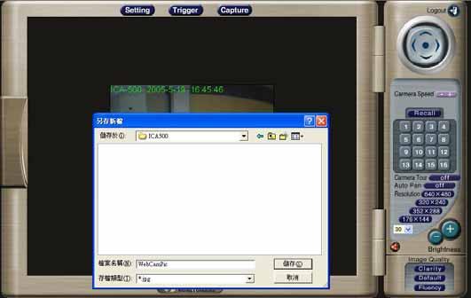
44 Trigger Settings FTP Upload a captured image to server Mail Mail captured image to specific mail address Image Memory Save images in attached CF memory card Alarm 1 Enable Alarm output 1 Alarm 2 Enable Alarm output 2 Clear Alarm 1 Clear alarm1 output status Clear Alarm 2 Clear alarm2 output status Capture: This screen is displayed when you click the Capture menu and the function can capture current image and save it to storage media. The image is saved in the JPEG format. ActiveX Control This feature only supports on the ActiveX control within Microsoft Internet Explorer. 40
45 View This screen is displayed when you click the View menu on the ActiveX control. View Settings Resizable Actual size Status Bar Make the image is resizable, but Actual size disable, the Splits is supported on this mode. Make the image show as the actual size, the Splits function does not work on this mode. A status bar display on the button of the image. 41
46 Split This screen is displayed when you click the Split menu on the ActiveX control. The Network Camera provides four setting for Window split, it can display different time frame images of the selected Network Camera. The time string with green characters is the current displayed image. Available Split: 1 x 1 (Default) 2 x 2 3 x 3 4 x 4 Rotate & Quality & Resolution Rotate: An image can be rotated in predefined 180-degree increments. Quality: Available quality : High (Default) Low. Resolution: Available resolution: 176x x x x480 Image Recording This screen is displayed when you click the Image Recording menu on the ActiveX control. 42


47 Recoding Screen Save as JPEG: Select this option and click Save as JPEG for detailed configurations. The predefined schedule can be set by JPEG. During the JPGEG file recording, a red icon displays on lower right position of the image to indicate the AVI saving process. If want stop the recording, please press the Stop Image Recording to stop the save as JPEG process. 43
48 Save as AVI: Select this option and click Save as AVI for detailed configurations. The pre-defined schedule can be set by AVI. During the AVI file recording, a red icon displays on lower right position of the image to indicate the AVI saving process. If want stop the recording, please press the Stop Image Recording to stop the save as AVI process. Recording File Path: Save Current Picture As This screen is displayed when you click the Save Current Picture As menu on the ActiveX control. How to configure Motion Detection Please select the Save Current Picture As to save the current display image into the local PC. Please input the saved file name, and click Save button. Please select the file to display the saved image by using any one of graph editing tools. 44
49 45

50 Chapter 5 Client UTILITY 5 INSTALLATION The CamView utility for ICA-500 is a powerful utility for video recording, viewing, and camera administrations. Please insert the user s manual CD and start the CamView installation from the default page or manually browse the Utility folder in the CD to install the software: 5.1. CamView Installation Run the setup.exe to start installation. A welcome message is shown as the following figure, and then hit the Next button to continue. Read the license agreement first, please. If you accept the agreement, select I accept the agreement, and then hit the Next button to continue. 46


51 Decide which directory to install the software. By default, just hit the Next button to continue 47
52 Decide the program group name. By default, just hit the Next button to continue. Decide whether to create a desktop icon of the program. By default, just hit the Next button to continue. 48


53 Ready to install. By default, just hit the Install button to start installation. 49

54 Installing, wait for a moment. Installation complete. Press Finish to launch the program. Otherwise, uncheck the check box to run the program later. 50

55 HOW TO USE After successfully installing the utility, this icon, Double click on it to launch the program., will be added to the desktop. 51

56 5.2. CamView User Interface CamView main screen Date and Time The current date and time of the computer are displayed here Viewer Screen CamView is able to monitor up to 16 Internet cameras. Users may choose different layout to monitor different sites. The available camera display modes are shown below: Single: Only one viewer displays video. 2 x 2: The screen is divided into 4 sub-screens. 3 x 3: The screen is divided into 9 sub-screens. 4 x 4: The screen is divided into 16 sub-screens Camera and Layout Selection Here is a combo box to select cameras. When you select a camera here, you can press buttons below the combo box to start the recording, snapshot tasks and so on. Moreover, there are four buttons for you to specify the layout of the screen Recording and Playback Here are buttons to record, snapshot and playback Camera and Application Settings Here are buttons to set the camera or the application program. 52
57 Camera Zoom Here are two buttons to zoom in or zoom out on the image. Note: camera zoom feature is reserved for future PTZ model Camera Pan/Tilt Control Here are five buttons to move the camera to the up, down, left, right and home, respectively Camera Selector and Recording Here are buttons to select cameras, and toggle buttons for recording Alert Message Here is a combo box to show alert messages. Ex: free space is almost exhausted Application Configuration Press the button shown below to configure the application program. After the button is pressed, a dialog form will show up. Users then configure the program by the form as the following sections Initial Setup Settings Figure shows settings for the global scope of the application including initialization and environment. After all settings are complete, press the OK button to save the configuration, and exit the form. The following lists descriptions of each setting: Viewer Layout: Set the initial layout of cameras when starting CamView. 53

58 Camera Settings Figure The Application Tab As shown in Figure 5.3.2, users can set parameters of each camera. If the Restore button is pressed, the current setting modifications of the specified camera will be cleared and restore to the original. If the Apply button is pressed, the current setting modifications will be applied to the specified camera. Note that these modifications are not saved to the persistent storage like HD on the computer. If the OK button is pressed, all settings on all tabs will be saved, and exit the form. The following lists descriptions of each setting: IP: IP of the camera. Port: Connection port of the camera. The default is 80. Record Path: A directory storing recorded video files. Double-click the input field or click the button to select the directory. Record Number of Frame: The maximum number of images in a video file. Snapshot Path: A directory storing snapshots. Double-click the input field or click the button to select the directory. Recording at Start: If the box is checked, the program will do recording for the specified camera automatically at the time it is started running. 54

59 Figure The Camera Tab Scheduling As shown in Figure 5.3.3, users can schedule recording tasks. When you press the Add button, the editing task will be added to the schedule item list. When the Modify button is pressed, the specified task will be updated. If the Remove button is pressed, the specified task will be removed from the list. The Apply button is unused for this tab. Press OK button will save all settings on all tabs, and exit the form. The following lists descriptions of each setting: Hour: Set the hour of time in 24- hour manner. * stands for all hours. Minute: Set the minute of time. * stands for all minutes. Month: Set the month of date. * stands for all months. Day: Set the day. * stands for all days. Weekday: Set the weekday of a week. If no day is specified, all weekdays will fit. Duration: The duration of the task. Set the value in seconds. Zero means no limit. For example, set a recording task which begins at 10:00 every Monday with duration 3600 seconds. It is: Hour = 10, Minute = 0, Month = *, Day = *, Weekday = Mon, Duration =

60 Figure The Scheduling Tab Application Settings Figure shows settings for the global scope of the application including initialization and environment. After all settings are complete, press the OK button to save the configuration, and exit the form. The Apply button is unused for this tab. The following lists descriptions of each setting: Alert Free Percentage (%): Set the percentage of free space you want to designate for alerts. Alert Free Size (MB): When free space is less than the specfied size, it will alert warning messages automatically. Message Numbers: Set the number of lines, which you want to show the alert message in. Export: Select the item to save the configuration (Application Configuration or emap) Import: Select the item to load the configuration (Application Configuration or emap) Cycle Recording: IF free space is not enough, it will delete the oldest recording file. 56

61 Figure The Application Tab 5.4. Camera Configuration Users can hit the button shown in Figure 5.4 to configure the specified camera. The configuration guide is not included in the document. Please read the documentation of the camera. Figure Recording There are three methods to start recording. The first is to press the toggle button as shown in Figure to start recording for the camera specified by the selector combo box on the right-top side of the panel. To stop recording, hit the button again. The second method is to use buttons described in section You may select a camera by hitting the button with camera number as shown in Figure and then press the corresponding button at the second line to record. The button is shown as in Figure After hitting the button, it will light up as shown in Figure to indicate the specified camera is recording. To stop recording is similar to the previous steps, press the lighten-up button can stop the video recording. The last method to record video is done by scheduling. Please setup the schedule recording tasks as described in section When the time is up, the program will start to record. 57

62 Figure Figure Figure Figure Playback When you press the Playback button on the panel as shown in Figure 5.6, a form will appear to show the list of video records and snapshots. Figure Video List The video list tab lists video records, and displays the information about the specified record. When you hit the Play button, the Windows Media Player will start to play the video. The Video list is shown in the following figure. Figure The Video List Tab Snapshot List The snapshot list tab lists snapshots, and displays the information about the specified snapshot. When you hit the Show button, Internet Explorer will be invoked to display the snapshot. 58


63 Figure The Snapshot List Tab Video Search The video search tab lists video file information about the specified search. When you enter the search qualification, then hit the Search button, you will get the matched video files. Select an item, hit the Play button, Windows Media Player will be opened to play the video. It is shown in the following figure. Figure The Video Search Tab 59
64 5.7. Image Rotation After the button is pressed, the display image rotates 180 degree. It is used for the camera being installed upside-down direction. Note video/images in recorded video will not be rotated. Figure emap When you press the emap button on the panel as shown in Figure 5.8, a form will appear to show the emap function. Figure emap Setting Select the File from the menu bar and follow these steps to set up emap : 1.New Layout: First, create a new layout. 2.Load Image: Choose an image file to load. 3.Save: Save all settings. The following describes other menu options: Reset: Remove all camera icons in this layout. Delete: Delete the editing layout. Close: Exit emap. Before you select it, we recommend you to save the current settings. As shown in Figure and Figure 5.8.2, with the map image in layout, you can drag the camera icons into proper positions to deploy your cameras. The following describes layout entries: Name: Define a name for this layout. Position: Describe the layout position. In the menu bar, select Layout to change editing layouts. 60


65 Figure Layout example 1 Figure Layout example 2 61

66 When your mouse moves over the camera icon, you can click the right button to display a menu which has options to set the configuration, show the record list, record, show video and remove the camera icon. Figure

67 Appendix A Alarm I/O Connector Appendix A Alarm I/O Connector The terminal block is used in applications for e.g. motion detection, event triggering, time lapse recording, alarm notification via , image storage to FTP locations, etc. ICA-500 provides a general I/O terminal block with two digital inputs and two outputs for device control. Pin 1 and 2 can be connected to an external sensor 1. Pin 2 and 3 can be connected to an external sensor 2. Both of the inputs, the voltage will be monitored from the initial state LOW. The relay switch of pin 4, 5 and 6 can be used to turn on or off the external device. The relay switch of pin 7 and pin 8 can be used to turn on or off the external device. External Inputs/Outputs are working independently. Pin Function 1 Alarm Input #1 (A). Max 24VDC, 12mA. 2 Alarm Input #1/2 (K). 3 Alarm Input #2 (A). Max 24VDC, 12mA 4 Alarm Output #1 (NC). Max 24VDC, 1A 5 Alarm Output #1 (COM) 6 Alarm Output #1 (NO) 7 Alarm Output #2 (COM). Max 24VDC, 1A 8 Alarm Output #2 (NO) 63
Pan and Tilt Network Camera
 Pan and Tilt Network Camera User s Guide Software Version 2.1.7 1/95 PT IP Cam / IR IP Cam / Video Server Series 2004~2005. Owner's Record The model and serial numbers are located at the bottom. Record
TENVIS Technology Co., Ltd. User Manual. For H.264 Cameras. Version 1.0.0
 TENVIS Technology Co., Ltd User Manual For H.264 Cameras Version 1.0.0 Catalogue Basic Operation... 3 Hardware Installation... 3 Search Camera... 3 For Internet Explorer... 6 Playback Record Files... 9
Internet Camera ICA-102/ICA-102W
 Internet Camera ICA-102/ICA-102W User s Manual Copyright Copyright (C) 2004 PLANET Technology Corp. All rights reserved. The products and programs described in this User s Manual are licensed products
GRAND IP VIDEO SERVER PRO. User s Manual INDEX
 INDEX GRAND IP VIDEO SERVER PRO Video & Audio Transmission/ iphone Web Browser Support User s Manual ISSUE:Mar 16, 2010 1. Package Contents.... 1 2. Introduction.... 1 3. System Requirements...... 1 4.
IP Camera. User Manual
 501583 IP Camera User Manual Version: 1.2 Released Date: June., 2005 Contents 1. Introduction... 3 2. Package Content... 3 3. System Requirement... 3 4. Hardware Installation... 4 4.1. LED and Focusing...4
IP-001T Video Server Products Series. User Manual & Installation Guide
 Page 1 of 29 IP-001T Video Server Products Series User Manual & Installation Guide Version: 1.0 Page 2 of 29 Table of Contents TABLE OF CONTENTS...2 WHAT IS VIDEO SERVER?...3 PRODUCT FEATURES...3 2. PHYSICAL
C1002 IP Camera. Quick Installation Guide. Solwise Ltd., 1
 C1002 IP Camera Quick Installation Guide Solwise Ltd., www.solwise.co.uk, sales@solwise.co.uk 1 Trademarks and/or registered trademarks are the property of their respective owners The information presented
Internet Camera Quick Installation Guide
 Internet Camera Quick Installation Guide Rev. 01 (Dec, 2001) Q20011203 Printed In Taiwan Table of Content INTRODUCTION...2 SYSTEM REQUIREMENT...3 INTERNET CAMERA... 3 Network:...3 Recommended PC or Notebook
Dual Mode CCD Dome Internet Camera
 Dual Mode CCD Dome Internet Camera ICA-510 User s Manual Copyright Copyright (C) 2008 PLANET Technology Corp. All rights reserved. The products and programs described in this User s Manual are licensed
Internet Camera. User Manual
 Internet Camera User Manual Version: 1.1 Released Date: Dec., 2004 Contents 1. Introduction... 3 2. Package Content... 3 3. System Requirement... 3 4. Hardware Installation... 4 4.1. LED and Focusing...4
Digital Video Recorder DVR-400. User s manual
 Digital Video Recorder DVR-400 User s manual 1 Copyright Copyright (C) 2005 PLANET Technology Corp. All rights reserved. The products and programs described in this User s Manual are licensed products
SOHO NETWORK IP CAMERA USER MANUAL
 SOHO NETWORK IP CAMERA USER MANUAL MODEL 503365 INT-503365-UM-0407-02 Contents section page 1. Introduction... 1 2. Package Contents... 2 3. System Requirements... 2 4. Hardware Installation... 3 4.1 LED
Network / IP Camera User Manual
 Network / IP Camera User Manual Preface Congratulations on your purchase of this product. Read this manual carefully and keep it in a safe place for future reference. About this manual This user manual
LOREX CLIENT 3.0 SOFTWARE MANUAL IRMS Integrated Remote Management Software
 LOREX CLIENT 3.0 SOFTWARE MANUAL IRMS Integrated Remote Management Software Instruction Manual English Version 2.0 Copyright 2007 Lorex Technology Inc. www.lorexcctv.com Table of Contents Overview... -
Video Server D1. User s Manual
 Video Server D1 User s Manual i Video Server D1 10 th Oct, 2004 Table of Contents H1 INTRODUCTION 1-1 1.1 PACKAGE CONTENTS...1-1 1.2 FEATURES AND BENEFITS...1-2 1.3 PHYSICAL DESCRIPTION...1-4 1.3.1 RS-485
LevelOne. User Manual. FCS-0020 P/T/Z IP Network Camera. WCS b/g Wireless P/T/Z IP Network Camera. Ver
 LevelOne User Manual FCS-0020 P/T/Z IP Network Camera WCS-0020 11b/g Wireless P/T/Z IP Network Camera Ver. 1.1.0-0809 Safety FCC This equipment has been tested and found to comply with Part 15 of the
Veo Europe VSD-2000_PT_IR Observer IP Speed Dome Pan/Tilt with Infra/Red Products Series. User Manual & Installation Guide
 Page 1 of 32 Veo Europe VSD-2000_PT_IR Observer IP Speed Dome Pan/Tilt with Infra/Red Products Series User Manual & Installation Guide Version: 1.0 Date: August 24, 2005 Page 2 of 32 Table of Contents
Configuring and Managing the IP Camera
 CHAPTER 3 The Cisco Video Surveillance IP Camera provides configuration windows that you use to configure and manage the IP camera. This chapter explains how to access the configuration windows, describes
DCS-900. Manual. Internet Camera. Version Building Networks for People (10/04/04)
") DCS-900 Internet Camera Manual Version 1.50 Building Networks for People (10/04/04) Contents Package Contents...3 Introduction...4 Hardware Installation...9 Security...10 Using the Setup Wizard... 11 DCS-900
DCS-900 Internet Camera Manual Version 1.50 Building Networks for People (10/04/04) Contents Package Contents...3 Introduction...4 Hardware Installation...9 Security...10 Using the Setup Wizard... 11 DCS-900
Remote Monitoring System. User Manual DVR8A+/ 16B+ DVR4/ 8/ 16E+
 Remote Monitoring System User Manual For DVR Model (Version 1.02.004 Onwards): DVR8A+/ 16B+ DVR4/ 8/ 16E+ ifocus Pte Ltd Copyright Statement Copyright 1999-2008. Version 3.1 All rights reserved. No part
BlackHawk for MAC Software User Guide
 BlackHawk for MAC Software User Guide Products: BLK-DH2 Series and BLK-HD Series DVRs Please read this manual before using your software, and always follow the instructions for safety and proper use. Save
XIPLED Software User s Manual. For Firmware release V3.5.0.*
 XIPLED1080-36 Software User s Manual For Firmware release V3.5.0.* Product name: XIPLED1080-36 Release Date: 2014/10/02 Manual Revision: V02 Feature XIPLED1080-36 Live View All Series Camera/Video/Audio
M511E Pan/Tilt Day/Night IP Camera Firmware User Manual
 0 M511E User Manual M511E User Manual M511E Pan/Tilt Day/Night IP Camera Firmware User Manual - Contents - CHAPTER 1. MINIMUM SYSTEM REQUIREMENT... 2 CHAPTER 2. USING IP CAMERA VIA WEB BROWSER... 3 2.1WINDOWS
Cisco WVC210 Wireless-G Pan Tilt Zoom (PTZ) Internet Video Camera: 2-Way Audio Cisco Small Business Video Surveillance Cameras
 Internet Video Camera: 2-Way Audio Cisco Small Business Video Surveillance Cameras") Cisco WVC210 Wireless-G Pan Tilt Zoom (PTZ) Internet Video Camera: 2-Way Audio Cisco Small Business Video Surveillance Cameras High-Quality, Flexible, Remote-Controlled Wireless Video Solution for Your
Cisco WVC210 Wireless-G Pan Tilt Zoom (PTZ) Internet Video Camera: 2-Way Audio Cisco Small Business Video Surveillance Cameras High-Quality, Flexible, Remote-Controlled Wireless Video Solution for Your
IP Kamera 9000A Plus User Guide
 IP Kamera 9000A Plus User Guide IP KAMERA 9000A PLUS USER MANUAL User Guide IP Kamera 9000A Manual version: 2.32 Date: SEP 20, 2004-1 - VER. 2.32, Caution: Any changes or modifications not approved by
IP SERVER 9310 User Manual
 IP SERVER 9310 User Manual USER MANUAL IP Server 9310 Version: 1.0 2007.3-1 - Warning: any changes to this equipment without permission may cause damages to your equipment! This equipment has been proved
F510E BOX IP Camera. Firmware User Manual
 0 F510E User Manual F510E BOX IP Camera F510E User Manual Firmware User Manual - Contents - CHAPTER 1. MINIMUM SYSTEM REQUIREMENT... 2 CHAPTER 2. USING IP CAMERA VIA WEB BROWSER... 3 CHAPTER 3. USING IP
LevelOne FCS Mbps IP Network Camera User s Manual
 LevelOne FCS-1020 100Mbps IP Network Camera User s Manual Contents 1. Introduction...3 2. Package Content...3 3. System Requirement...3 4. Hardware Installation...4 4.1. LED and Focusing...4 4.2. Camera
Cisco WVC210 Wireless-G Pan Tilt Zoom (PTZ) Internet Video Camera: 2-Way Audio Cisco Small Business Video Surveillance Cameras
 Internet Video Camera: 2-Way Audio Cisco Small Business Video Surveillance Cameras") Cisco WVC210 Wireless-G Pan Tilt Zoom (PTZ) Internet Video Camera: 2-Way Audio Cisco Small Business Video Surveillance Cameras High-Quality, Flexible, Remote-Controlled Wireless Video Solution for Your
Cisco WVC210 Wireless-G Pan Tilt Zoom (PTZ) Internet Video Camera: 2-Way Audio Cisco Small Business Video Surveillance Cameras High-Quality, Flexible, Remote-Controlled Wireless Video Solution for Your
IP WEB User Manual V2.0
 IP WEB User Manual V2.0 Please read carefully before installing or contacting your supplier. The information contained at the time of printing is correct, but is subject to change without notice. This
Internet Camera. User s Guide
 Internet Camera User s Guide TABLE OF CONTENTS ABOUT THIS GUIDE...5 INTRODUCTION...6 SYSTEM REQUIREMENT...7 INTERNET CAMERA... 7 Network:...7 Recommended PC or Notebook to Access the Internet Camera...7
HooToo IP Camera User Manual(part two)
") HooToo Inc. HooToo IP Camera User Manual(part two) For Model: HT-IP210P Published by SunvalleyTek Group 2014/9/14 Content 1. IPCamClient (windows software)...3 Set up...3 CAM... 13 Local Setting... 13
HooToo Inc. HooToo IP Camera User Manual(part two) For Model: HT-IP210P Published by SunvalleyTek Group 2014/9/14 Content 1. IPCamClient (windows software)...3 Set up...3 CAM... 13 Local Setting... 13
LevelOne FNS bay/1usb Soho NAS. User s Manual
 LevelOne FNS-1000 1- bay/1usb Soho NAS User s Manual Table of Contents Introduction... 2 The FNS-1000 NAS Server... 2 FNS-1000 Features... 2 Package Contents... 2 System Requirements... 2 Disclaimer...
wificam User's Guide Report Version: Date: November
 User's Guide Report Version: 2.0.3 Date: November 9 2004 3JTech Co., Ltd. 342 Fu-Hsing N. Rd., 2F Taipei, Taiwan Tel: +886-2-2500 6919 e-mail: info@3jtech.com.tw 1 Revision History Version Date Changes
Multi-NVR Manager. Quick Start Configuration Usage
 Multi-NVR Manager Quick Start Configuration Usage 2014. All rights are reserved. No portion of this document may be reproduced without permission. All trademarks and brand names mentioned in this publication
IP / CCTV OUTDOOR SPEED DOME CAMERA
 242Z IP / CCTV OUTDOOR SPEED DOME CAMERA Quick Installation Guide All lead-free products offered by the company comply with the requirements of the European law on the Restriction of Hazardous Substances
GV-IP Decoder Box Plus User s Manual
 GV-IP Decoder Box Plus User s Manual Before attempting to connect or operate this product, please read these instructions carefully and save this manual for future use. DBPV10-UM-A 2015 GeoVision, Inc.
Installation Instructions Fig. 3 Side View. No. Label Operation
 One-Camera IP Video Server In G Out G D+ D- Installation Instructions 1507280 Part Number: CM2002 - One-Camera IP Video Server CM2002 IP Video Server Features In G Out G D+ D- DO G DI G Out In Video In
Lorex Client 7.0 & Lorex Message Master
 Lorex Client 7.0 & Lorex Message Master Software Manual English Version 1.0 MODELS: L19WD Series www.lorexcctv.com Includes L19WD800 & L19WD1600 Copyright 2008 Lorex Technology Inc. Table of Contents Table
NVR Equipment WEB Operation Guide ISSUE V1.1 DATE
 NVR Equipment WEB Operation Guide ISSUE V1.1 DATE 2018-05-15 About This Document About This Document Purpose This document describes how to use the web management system for NVR and the cameras managed
VIH Series IP Camera. User s Manual V_
 VIH Series IP Camera User s Manual V_1.0-1 - Contents Table Over View... 1 Installation... 2 Live View... 9 Setup... 10 4.1 Status... 10 4.2 Network... 11 4.3 Stream... 12 4.4 Imaging... 13 4.5 Security...
Central Management Software. Cam Viewer 3 Lite. User Manual
 Central Management Software Cam Viewer 3 Lite User Manual Version 1.0.0 Table of Contents 1. System Requirement...4 2. Software Installation...5 3. Configuration Wizard...9 3.1 Channel...10 3.1.1 Adding
VoIP Analog Telephone Adapter VIP-158 User s manual Version 1.00
 VoIP Analog Telephone Adapter VIP-158 User s manual Version 1.00-1 - Copyright Copyright (C) 2007 PLANET Technology Corp. All rights reserved. The products and programs described in this User s Manual
Wireless Network Video Recorder
 LD2R/LD2R500 Wireless Network Video Recorder User Guide Version 1.0 PREFACE Thank you for purchasing the Wireless Network Video Recorder, an IP based device that installed on your network, which can be
NVR-0316 User s Manual 1 NVR User s Manual. Version 1.0.0
 NVR-0316 User s Manual 1 NVR-0316 User s Manual Version 1.0.0 2 NVR-0316 User s Manual Table of Contents Hardware... 4 Overview... 4 LED & Buttons Definitions... 4 Connect to the NVR... 5 Use NVR Search
InPro Camera SpecoView
 InPro Camera SpecoView Speco Technologies 200 New Hwy Amityville NY 11701 TEL: 1-800-645-5516 Http://www. specotech.com INPRO CAMERA SPECOVIEW... 1 INTRODUCTION... 4 INSTALL SPECOVIEW PROGRAM... 5 STARTUP
VMS-A1 Client Software. User Manual
 VMS-A1 Client Software User Manual Contents Contents... 2 Chapter1. Overview... 4 1.1 Description... 4 1.2 Features & Functions... 4 Chapter2. Update Info... 6 Chapter3. Starting VMS-A1... 7 3.1 Installing
F312A IP Camera. Firmware User Manual
 0 F312A User Manual F312A IP Camera F312A User Manual Firmware User Manual - Contents - CHAPTER 1. MINIMUM SYSTEM REQUIREMENT...2 CHAPTER 2. USING IP CAMERA VIA WEB BROWSER...3 2.1WINDOWS WEB BROWSER...3
Powerline Communication
 Networking & Communication Powerline Communication Powerline to Ethernet Converter PL-101E USB to Powerline Network Adapter - PL-101U USER S MANUAL 1 Copyright Copyright (C) 2002 PLANET Technology Corp.
H.264 Multi-Profile 1-Channel Video Server
 H.264 Multi-Profile 1-Channel Video Server User s Manual Software Version 5.a.1.xxxx Owner's Record The model and serial numbers are on the device. Record these numbers in the spaces provided below. Refer
AVI321 / 311 Network Camera Series Quick Guide
 242Z AVI321 / 311 Network Camera Series Quick Guide All lead-free products offered by the company comply with the requirements of the European law on the Restriction of Hazardous Substances (RoHS) directive,
IP806GA/GB Wireless ADSL Router
 IP806GA/GB Wireless ADSL Router 802.11g/802.11b Wireless Access Point ADSL Modem NAT Router 4-Port Switching Hub User's Guide Table of Contents CHAPTER 1 INTRODUCTION... 1 Wireless ADSL Router Features...
CCTV42 System2 DVR Quick Start Guide 4/8/16-Ch DVR
 CCTV42 System2 DVR Quick Start Guide 4/8/16-Ch DVR If you have purchased a DVR / Hard drive package from us then we will have already installed the hard drive(s) and configured the basic settings on your
CHAPTER 7 ADVANCED ADMINISTRATION PC
 ii Table of Contents CHAPTER 1 INTRODUCTION... 1 Broadband ADSL Router Features... 1 Package Contents... 3 Physical Details... 4 CHAPTER 2 INSTALLATION... 6 Requirements... 6 Procedure... 6 CHAPTER 3 SETUP...
Operating Instructions
 KX-HGW500 WIRELESS LAN1 LAN2 LAN3 LAN4 INTERNET POWER Network Camera Management System Operating Instructions Model No. KX-HGW600 Please read this manual before using and save this manual for your future
Streamer VIP User s Manual
 Streamer VIP User s Manual About the Cover Image The cover image illustrates a Streamer VIP V2.3. A wireless version of the Streamer VIP that includes an external antenna is available also. This manual
IP Kamera 9060A -SL User Guide
 IP Kamera 9060A -SL User Guide IP Kamera 9060A-SL Manual version: 1.03 Date: 2008.05 1 Caution: Any changes or modifications not approved by the party responsible for compliance could void the user s authority
Video Surveillance Management Software NVClient V5 User Manual
 Video Surveillance Management Software NVClient V5 User Manual Version: V5.0 Update Date: 2013-12-12 Welcome Thanks for using the Company's digital video surveillance management software. Please read this
DCS Manual. Audio Internet Camera. Version Building Networks for People (10/04/04)
") DCS-2000 Audio Internet Camera Manual Version 3.40 Building Networks for People (10/04/04) 2 Contents Contents of Package...3 Introduction...4 Features and Benefits...4 Connections...6 Hardware Installation...8
DCS-2000 Audio Internet Camera Manual Version 3.40 Building Networks for People (10/04/04) 2 Contents Contents of Package...3 Introduction...4 Features and Benefits...4 Connections...6 Hardware Installation...8
NS15WG 1080P Web App User Manual
 NS15WG 1080P Web App User Manual Table of Contents 1. Getting Started... 4 Download the Web App...4 2. Web App Top Menu... 5 Live Video...6 Video Playback...6 Settings...6 3. Device Configuration... 6
LevelOne Broadband Routers
 LevelOne Broadband Routers FBR-1100TX FBR-1400TX FBR-1401TX FBR-1700TX User's Guide TABLE OF CONTENTS CHAPTER 1 INTRODUCTION... 1 Features of your LevelOne Broadband Router... 1 Package Contents... 4
Wireless-G Router User s Guide
 Wireless-G Router User s Guide 1 Table of Contents Chapter 1: Introduction Installing Your Router System Requirements Installation Instructions Chapter 2: Preparing Your Network Preparing Your Network
RVS4000 Remote Video Server
 RVS4000 Remote Video Server Operator s Guide Figure 1: RVS4000 hardware RVS4000 Remote Video Server STATUS NETWORK POWER PRESET RESET Figure 2: RVS4000 software startup window About this Guide This operator
NUBIX H.264 DVR Setup Guide
 Package Content NUBIX H.264 DVR Setup Guide Inspect the packaging carton. Make sure the NUBIX H.264 DVR is properly delivered. Remove all items from the box and make sure the box contains the following
USER GUIDE STAND-ALONE. 4 channel MPEG-4 Triplex DVR V Stand-Alone DVR User Guide
 USER GUIDE STAND-ALONE 4 channel MPEG-4 Triplex DVR V. 1.4 This document contains preliminary information and subject to change without notice. SAFETY PRECAUTIONS EXPLANATION OF SYMBOLS This symbol is
TABLE OF CONTENTS COPYRIGHT INTRODUCTION...3 PRODUCT OVERVIEW...3 COMPONENTS AND FEATURES...3 HARDWARE INSTALLATION
 TABLE OF CONTENTS COPYRIGHT...2 1. INTRODUCTION...3 PRODUCT OVERVIEW...3 COMPONENTS AND FEATURES...3 HARDWARE INSTALLATION...3 2. MFP SERVER INSTALLATION...5 PREPARATION...5 CONFIGURATION SOLUTION TABLE...5
Video Server. User s Guide IVS400A IVS400B
 Video Server User s Guide IVS400A IVS400B Caution: Any changes or modifications not approved by the party responsible for compliance could void the user s authority to operate the equipment. Note: This
H.264 P/T Mega-Pixel / Multi-Profile Network Camera
 H.264 P/T Mega-Pixel / Multi-Profile Network Camera User s Manual Firmware Version 5.0.0 Owner's Record The model and serial numbers are located at the bottom of device. Record these numbers in the spaces
VG422R. User s Manual. Rev , 5
 VG422R User s Manual Rev 1.0 2003, 5 CONGRATULATIONS ON YOUR PURCHASE OF VG422R... 1 THIS PACKAGE CONTAINS... 1 CONFIRM THAT YOU MEET INSTALLATION REQUIREMENTS... 1 1. INSTALLATION GUIDE... 2 1.1. HARDWARE
CMOS/Mega-Pixel CMOS/CCD Internet Camera ICA-230 / ICA-M230 / ICA-501. Quick Installation Guide
 CMOS/Mega-Pixel CMOS/CCD Internet Camera ICA-230 / ICA-M230 / ICA-501 Quick Installation Guide Table of Contents Chapter 1. Introduction... 3 1.1 Before Installation... 3 1.2 System Requirements... 3 1.3
Quick Start Guide 4/8/16-CH DVR.
 Quick Start Guide 4/8/16-CH DVR 1. Install Hard Drive &DVD Writer 1.1 Install Hard Drive Notice: 1. Support two SATA hard drives. Please use the hard drive the manufacturers recommend specially for security
IS-BX-12 User Manual
 IS-BX-12 User Manual Ver 1.0 Sentry360 2014 Table of Contents 1. Overview...3 1.1 Features... 3 1.2 Package Contents... 4 1.3 Dimensions... 4 1.4 Connectors... 5 1.5 Light Sensor... 6 2. Camera Cabling...6
Broadband Router DC-202. User's Guide
 Broadband Router DC-202 User's Guide Table of Contents CHAPTER 1 INTRODUCTION... 1 Broadband Router Features... 1 Package Contents... 3 Physical Details...3 CHAPTER 2 INSTALLATION... 5 Requirements...
Configuring and Managing the IP Camera
 CHAPTER 3 The Cisco Video Surveillance IP Camera provides configuration windows that you use to configure and manage the IP camera. This chapter explains how to access the configuration windows, describes
User Manual. For H.264 Cameras. Version 2.0.0
 User Manual For H.264 Cameras Version 2.0.0 Catalogue Basic Operation... 3 Camera Settings... 3 System... 3 Device Name... 4 Time... 4 User... 4 Network... 5 IP... 5 Port... 5 WiFi... 6 UPnP... 6 DDNS...
 DESCRIPTION ------------------------------------------------------------------------------------------------------------------------------------- The HEB Series camera is an internet protocol based megapixel
RAS (Remote Administration System)
") RAS (Remote Administration System) Digital Video Recorder Software User Guide Document 900.0314 Rev 2.00 RAS User Guide Revisions Issue Date Revisions 1.00 08/04 New document. 1.01 04/05 Update template,
RAS (Remote Administration System) Digital Video Recorder Software User Guide Document 900.0314 Rev 2.00 RAS User Guide Revisions Issue Date Revisions 1.00 08/04 New document. 1.01 04/05 Update template,
IP Kamera 9060A MP (Mega Pixels) User Guide
 User Guide") IP Kamera 9060A MP (Mega Pixels) User Guide IP Kamera 9060A-MP Manual version: 1.00 Date: 2006.08 1 Caution: Any changes or modifications not approved by the party responsible for compliance could void
IP Kamera 9060A MP (Mega Pixels) User Guide IP Kamera 9060A-MP Manual version: 1.00 Date: 2006.08 1 Caution: Any changes or modifications not approved by the party responsible for compliance could void
SKY l SYS DVR USER S MANUAL TABLE OF CONTENTS. Skydreamers Systems DVR Page 1
 TABLE OF CONTENTS Main System Application (Control) SERVER Startup Screen 6 Login/Logout/Shutdown 7 Control Screen 7 Setup 7 System Power Management 8 Auto Switching Interval 8 E-map 8 TV-Out 8 On-screen
1. Introduction Overview Product Information... 3
 1. Introduction... 3 1.1 Overview... 3 1.2 Product Information... 3 2. Device Connection... 3 2.1 Connection Diagram... 3 2.2 Wi-Fi Setting... 4 2.2.1 Set up WiFi by Mobile Phone... 4 2.2.2 WPS/QSS One
Wireless IP Bird Box Camera
 Wireless IP Bird Box Camera Model: 4901-18 Operation and Installation Manual 1 WELCOME... 3 PRODUCT OVERVIEW... 4 HARDWARE INSTALLATION... 4 Attach the External Power Adapter... 4 SMARTPHONE OR TABLET
M511W Wireless Pan/Tilt IP Camera Firmware User Manual
 0 M511W User Manual M511W User Manual M511W Wireless Pan/Tilt IP Camera Firmware User Manual - Contents - CHAPTER 1. MINIMUM SYSTEM REQUIREMENT... 2 CHAPTER 2. USING IP CAMERA VIA WEB BROWSER... 3 2.1WINDOWS
Multi-Function Wireless A/P Router User s Guide
 Multi-Function Wireless A/P Router User s Guide Model CNWR-811P Wireless Access Point Router W / Printer Sharing TABLE OF CONTENTS CHAPTER 1 INTRODUCTION...1 CNWR-811P Features...1 Package Contents...3
LevelOne FBR User s Manual. 1W, 4L 10/100 Mbps ADSL Router. Ver
 LevelOne FBR-1416 1W, 4L 10/100 Mbps ADSL Router User s Manual Ver 1.00-0510 Table of Contents CHAPTER 1 INTRODUCTION... 1 FBR-1416 Features... 1 Package Contents... 3 Physical Details... 3 CHAPTER 2
Network Camera Recording and Monitoring System. Network Video Recorder. VK-64/ VK-16 v1.1. User s Manual. Ver. 1.1
 Network Camera Recording and Monitoring System Network Video Recorder VK-64/ VK-16 v1.1 Storage Server & Viewer User s Manual Ver. 1.1 Introduction Thank you for purchasing Network Video Recorder VK-64
errors, or places that do not match the product. If you have any unsolved please contact our technical support department.
 - 0 - Statement: This manual may contain several technical inaccuracies or typographical errors, or places that do not match the product. If you have any unsolved problems in the process of using product
Quick Start Guide 4/8/16/24-Ch DVR
 Quick Start Guide 4/8/16/24-Ch DVR 1.1 Install Hard Drive 4/8/16/24-CH DVR Quick Start Guide Notice: 1.4/3/16-ch DVR supports one SATA hard drive. 24-ch DVR supports three SATA hard drives. Please use
H.264 Mega-Pixel CMOS PT Internet Camera ICA-HM230. User s Manual
 H.264 Mega-Pixel CMOS PT Internet Camera ICA-HM230 User s Manual Version: 1.00 Date: May. 2009 1 Copyright Copyright 2009 by PLANET Technology Corp. All rights reserved. No part of this publication may
NET101. RS232 / RS422 / RS485 to Ethernet Converter. User s Manual. Version 1.2
 NET101 RS232 / RS422 / RS485 to Ethernet Converter User s Manual Version 1.2 Copyright Information Copyright 2004-2005, Mega System Technologies, Inc. All rights reserved. Reproduction without permission
NVMS1000. User Manual
 NVMS1000 User Manual Contents 1 Software Introduction... 1 1.1 Summary... 1 1.2 Operation Environment... 1 1.3 Install and Uninstall... 2 1.3.1 Install the Software... 2 1.3.2 Uninstall the Software...
Wireless PTZ Cloud Camera TV-IP851WC (v1.0r)
") (v1.0r) TRENDnet s Wireless PTZ Cloud Camera, model, takes the work out of viewing video over the internet. Previously to view video remotely, users needed to perform many complicated and time consuming
(v1.0r) TRENDnet s Wireless PTZ Cloud Camera, model, takes the work out of viewing video over the internet. Previously to view video remotely, users needed to perform many complicated and time consuming
Full HD WDR Mini Dome IP Camera
 Full HD WDR Mini Dome IP Camera User s Manual DN-16086 Ver. 1.0 Table of Contents 1. Overview... 2 1.1 Features... 2 1.2 Package Contents... 3 1.3 Dimensions... 4 1.4 Installation... 5 1.5 Connectors...
Lite H.264 DVR Setup Guide
 Package Content Lite H.264 DVR Setup Guide Inspect the packaging carton. Make sure the Lite H.264 DVR is properly delivered. Remove all items from the box and make sure the box contains the following items.
Installation Procedure Windows 2000 with Internet Explorer 5.x & 6.0
 Installation Procedure Windows 2000 with Internet Explorer 5.x & 6.0 Printer Friendly Version [ PDF 266K ] Before You Begin Before proceeding with the installation of a SOHO 6 appliance, you must have
VIP Kit 16 channel software manual. Set up and user manual for Vista s VIP Kit software IP CCTV system
 VIP Kit 16 channel software manual Set up and user manual for Vista s VIP Kit software IP CCTV system Table of Contents 1. Introduction of Program... 1 2. Preparations before operating... 1 2.1 Minimum
Internet Camera. User s Manual ICA-110/ICA-110W. Version 1.0
 Internet Camera ICA-110/ICA-110W User s Manual Version 1.0 Copyright Copyright (C) 2005 PLANET Technology Corp. All rights reserved. The products and programs described in this User s Manual are licensed
Installation Procedure Windows NT with Netscape 4.x
 Installation Procedure Windows NT with Netscape 4.x Printer Friendly Version [ PDF 232K ] Before You Begin Before proceeding with the installation of a SOHO 6 appliance, you must have the following: A
LevelOne WBR User s Manual. 11g Wireless ADSL VPN Router. Ver
 LevelOne WBR-3407 11g Wireless ADSL VPN Router User s Manual Ver 1.00-0510 Table of Contents CHAPTER 1 INTRODUCTION... 1 Wireless ADSL Router Features... 1 Package Contents... 5 Physical Details... 6 CHAPTER
truvision DVR 31 Quick Start Guide
 truvision DVR 31 Quick Start Guide Content Contact information 1 Package contents 1 Installation environment 1 Setting up the DVR 31 1 Connecting the devices 2 Turning on the DVR 31 2 Operating the DVR
WN-200HD. 2.0 Mega Pixel Wireless 150Mbps IPCamera. User s Manual
 WN-200HD 2.0 Mega Pixel Wireless 150Mbps IPCamera User s Manual i Copyright & Disclaimer Copyright & Disclaimer No part of this publication may be reproduced in any form or by any means, whether electronic,