Mini Probe. user manual. DM Models
|
|
|
- Geraldine Neal
- 5 years ago
- Views:
Transcription


1 Mini Probe user manual DM Models
2 1.0: Index Section Title Page 1.0 Index Safety Summary Introduction Components of the Mini Probe Mechanical Installation Positioning Mounting Cable Tip Adjustment Tip Replacement PIE / Probe Connections PIE / Probe Connections Grounding / Shielding Section Title Page 7.0 Specifications Measurement Measurement Mechanical Environmental Digital Electrical Interface Outline Drawings Outline Drawings - DM/05/S Outline Drawings - DM/1/S Return of Goods Solartron Sales Offices 1.0: Index
3 2.0: Safety Summary Terms in this Manual Warning statements identify conditions or practices that could result in personal injury or loss of life. CAUTION statements identify conditions or practices that could result in damage to the equipment or other property. Symbols in this manual This symbol indicates where applicable cautionary or other information is to be found. WARNINGS: Do not operate in an explosive atmosphere To avoid explosion, do not operate this equipment in an explosive atmosphere. This equipment is not intended for use in a safety critical environment. NOTES: This equipment contains no user serviceable parts This equipment must be returned to your Solartron dealer for all servicing and repair. Low Voltage This equipment operates at below the SELV and is therefore outside the scope of the Low Voltage Directive. 2.0: Safety Summary
4 3.0: Introduction The Mini Probe is a compact, low profile, transducer intended for measurements in confined spaces. The product is based on a parallel spring structure that is significantly more robust than a single leaf arrangement. This greatly improves the reliability of the sensor, extending its working life and allowing it to be used in more demanding applications, such as automatic gauges. The parallel spring also insures a high level of repeatability, both on axis and across axis, so that it can be used in dynamic applications where profiling is required. CAUTION The Mini Probe needs to be treated carefully, as with any precision instrument, to avoid damage during installation - please see section 5 of this manual. The Digital version of the Mini Probe, along with other digital products, can be connected to a PC or PLC via the Orbit Network system, or directly to one of Solartron s digital readouts. More detailed information on the Orbit Network can be downloaded from 3.0: Introduction
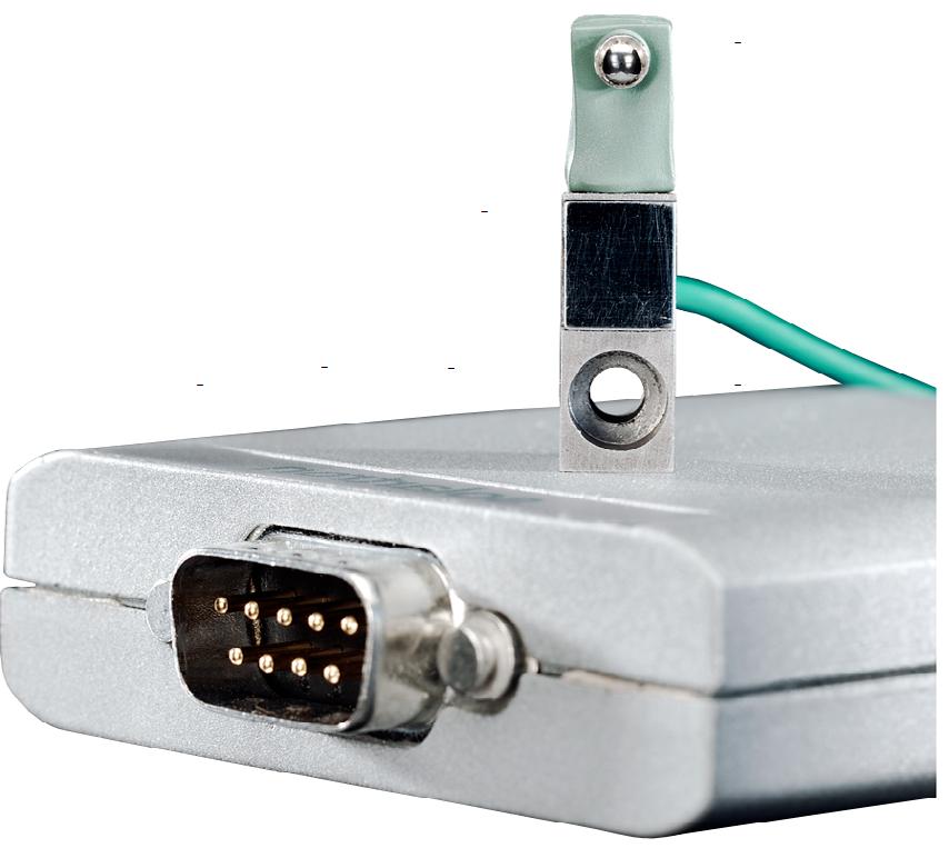
5 4.0: Components of the Mini Probe Adjustable Tip Location of M3 Mounting Screw Viton Boot Mounting Face Viton - Registered trademark of DuPont Performance Elastomers 4.0: Components of the Mini Probe
6 5.0: Mechanical Installation 5.1: Positioning The Mini Probe is susceptible to some degree to the influence of magnetic fields and should therefore be positioned well away from electric motors, relays and permanent magnets. To ease installation, the Mini Probe head can be disconnected from the PIE. It is important that the PIE with the correct indent is used with the corresponding Mini Probe head. 5.2: Mounting The centreline of the Mini Probe is accurately aligned to one side of the transducer to provide a reference datum face. Similarly, the rear face and base mounting face of the Mini Probe can be used as a datum. These datum faces are shown on the CAD drawing in section 8.1 DATUM Installation is simply a matter of positioning the device, and securing it via a single M3 screw (supplied with the Mini Probe).The probe head may be mounted in any orientation.. 5.0: Mechanical Installation
7 5.0: Mechanical Installation 5.3: Cable To minimise transducer failure due to cable damage, cable runs should be positioned well clear of moving components and vulnerable working areas. If the PUR cable is in a flex situation, then a minimum bend radius of 150mm should be maintained. A minimum bend radius of 1mm is recommended for the wires coming out of the probe head. These wires should not be subjected to regular bending. If a cable is damaged, it is not possible to repair it without affecting the probe calibration. The complete assembly (Mini Probe and PIE) must be replaced. WARNING When mounting the Mini Probe in a fixture, care must be taken as the probe can be damaged by the application of twisting forces. 5.0: Mechanical Installation
8 5.0: Mechanical Installation 5.4: Tip Adjustment The Mini Probe Tip height can be adjusted over a 0.5 mm range (± 0.25 mm from the factory set position -approximately ±½ turn). To adjust tip 1) Firmly hold the Mini Probe frame as shown, so that it is not stressed during the tip adjustment 5.5: Tip Replacement To remove tip 1) Firmly hold the Mini Probe frame, so that it is not stressed during the tip removal. 2) Using the spanner supplied, unscrew the tip from the Mini Probe. To install tip 2) Using the spanner supplied, turn the tip until the required tip extension is achieved.. 1) Firmly hold the Mini Probe frame, so that it is not stressed during the tip installation. 2) Using the spanner supplied, screw the replacement tip into the Mini Probe until the required tip extension is achieved. The tip is self-locking, so a tightening torque is not applicable. Do not tighten the tip against the stop. CAUTION In order to avoid damage to the probe, it is critical that the Mini Probe is held firmly whilst the tip is being adjusted. Failure to do so will stress the assembly and may damage the structure beyond repair. 5.0: Mechanical Installation
9 6.0: PIE / Probe Connections 6.1: PIE / Probe Connections To aid installation, the probe and PIE may be separated. Two connection styles are used. In order to maintain the calibration, it is important the PIE and probe head identities match. Labels are provided on cables to ensure the PIE can be matched with the corresponding probe head. Pin to Pin Connection Pull the in-line connections apart (handling the end of the connector only) and, at the same time, carefully slide back the sleeve to aid removal. hold end of connector only pull back sleeve from here Alternatively, slide the sleeve back to expose the connector. Push the pin and socket together and then slide the sleeve back into position. Ensure connectors are mating before pushing together Gently pull the ends of the sleeve to stretch it slightly. This puts a little tension into the sleeve and helps to pull the connector pins together. To reconnect, push the pin and socket together, feeling for the pin and socket making contact before finally pushing them together. When the probe is installed, ensure that the wires are not under tension. The connection method does not provide a positive locking. It is recommended that wires and cables are clamped or restrained in order to prevent the connectors being put under tension. 6.0: PIE / Probe Connections
10 6.0: PIE / Probe Connections 6.1: PIE / Probe Connections (continued) M5 Circular Connector To separate the probe and PIE, hold the probe connector and turn the locking ring only. When the locking ring is fully unscrewed the connector halves may be separated. Excessive cable twist may cause damage. Locking Ring 6.2: Grounding / Shielding Pin to Pin Connection It is recommended that the spade terminal be connected to the same metal work as the transducer. When multiple Mini Probes are being used, only one connection may be required. For installations where the PIE module and the probe are mounted close to each other on common metalwork, this extra connection may not be required. Probe Connector PIE Connector The unshielded wires from the transducer should remain loosely twisted and be contained within (or remain in close proximity to) the metalwork. These precautions will greatly improve the grounding / shielding aspects of the installation. M5 Circular Connector No additional screening precautions are required. The cable screens are continuous through the connector. For additional advice regarding grounding and shielding, contact your original supplier. 6.0: PIE / Probe Connections 10
11 7.0: Specifications 7.1: Measurement DM/05/S DM/1/S Mechanical Travel 0.6 mm 1.1 mm Measurement Range 0.5 mm 1.0 mm Start of Measuring Range 20 mm to 30 mm from limit stop 20 mm to 40 mm from limit stop Accuracy mm 6 D x 0.2% mm 6 D x 0.2% Operational Repeatability* using Standard tip On axis On cross axis On axis On cross axis at position 100 mm from limit stop 0.1 mm 0.1 mm 0.1 mm 0.1 mm at position 250 mm from limit stop 0.25 mm 0.15 mm 0.15 mm 0.1 mm at position 500 mm from limit stop 0.5 mm 0.25 mm 0.3 mm 0.15 mm Resolution 0.01 mm 0.01 mm Measurement Bandwidth Reading Speed Programmable from 6 Hz to 460 Hz Up to 3906 readings/second in Dynamic Measurement Mode Tip Force 0.7 N6 25% (when passing through the centre of the measurement range) Temperature Coefficient 0.08 mm / 8C * Obtained by step gauging : Repeatedly pushing the probe (bi-directionally) against the edge of the intended target prior to recording the measurement. This replicates the actual mini probe operation in the field. 7.0: Specifications 11
12 7.0: Specifications 7.2: Measurement The linearity specification includes errors due to both linearity and sensitivity, for both the Mini Probe and the electronics. Other manufacturers may quote these errors separately. Error (mm) mm 1000 mm Position Accuracy limits of Mini Probe including both sensitivity and linearity contributions. 7.0: Specifications 12
13 7.0: Specifications 7.3: Mechanical Mass Material of Chassis Material of Frame Gaiter Mounting < 15 g (<0.011 lbs) Chromium Steel Viton Retain using 1 x M3 screw (supplied with transducer) 7.4: Environmental Storage Temperature Operating Temperature IP Rating of Transducer IP Rating of Electronics Shock -20 8C to +85 8C 0 8C to +60 8C IP65 IP43 To maintain best performance, the Mini Probe should be protected from shock and dropping 7.5: Electrical Interface Energising Voltage Energising Current Interface 5 V V dc (powered from Orbit Network) Nominal 55 ma (at 5 V dc) (powered from Orbit Network) Orbit Network 7.0: Specifications 13
14 8.0: Outline Drawings 8.1: Mechanical Drawing - DM/05/S CAD drawings can be downloaded from Standard Product - tip and specifications may vary 8.0: Outline Drawings 14
15 8.0: Outline Drawings 8.2: Mechanical Drawing - DM/1/S CAD drawings can be downloaded from Standard Product - tip and specifications may vary 8.0: Outline Drawings 15
Analogue Input Module. user manual All Models
 Analogue Input Module user manual All Models 1.0: Index Section Title Page 1.0 Index......................... 1 2.0 Safety Summary................. 2 3.0 Introduction.................. 3 4.0 Installation....................
1.0: Index. Return Of Goods Solartron Sales Offices For drawings please contact 1.0: Index
 1.0: Index Section Title Page 1.0 Index................................. 1 2.0 Safety Summary......................... 2 3.0 Introduction Digital Probe, Linear Encoder and Orbit ACS.......................
Single Leaf Measurement Transducers
 Single Leaf Measurement Transducers A new range of Flexure Measurement Sensors Sensors to measure hard to reach areas such as bores and gaps Excellent resolution and repeatability Robust designs, good
Orbit system components 67
 system components 67 s well as many Orbit dimensional measurement devices, Solartron Metrology also offers a range of electrical interface modules for third party sensors and for general instrumentation
SI3300. user and installation manual. 4-20mA/DC-Digital Display
 SI3300 4-20mA/DC-Digital Display The SI3300 is a member of the SI3000 Readout Family. All members of the family are marked SI3000 on the front panel. This manual is specifically for the SI3300 Model with
Removal and Installation8
 8 Screw Types 8-4 Top Cover Assembly 8-5 Left Hand Cover 8-6 Right Hand Cover 8-10 Front Panel Assembly 8-14 Left Rear Cover 8-15 Right Rear Cover 8-16 Extension Cover (60" Model only) 8-17 Media Lever
User Manual. Confocal System
 User Manual Confocal System 503301 - User Manual for the Confocal System Contents 1. Introduction... 3 2. Safety Summary... 3 3. Trademarks and Copyrights... 4 4. Contact Information... 4 5. Documentation
Displacement Sensors High Performance Displacement Transducers S Series
 Displacement Sensors High Performance Displacement Transducers S Series Description The S Series Displacement Sensor is the accumulation of many years experience gained from Solartron s pedigree of producing
Keysight M8000 Series BER Test Solutions
 Keysight M8000 Series BER Test Solutions J-BERT M8020A High-Performance BERT M8030A Multi-Channel BERT M8040A High-Performance BERT M8041A, M8051A, M8061A, M8062A, M8045A, M8046A & M8057A Tips for Preventing
NT PRESSURE TRANSDUCER MODELS 4100, 4210, 4130, 4230
 P/N 0-027289 (Rev. A 04/4) NT PRESSURE TRANSDUCER MODELS 400, 420, 430, 4230 User Guide Table of Contents Safety Alert Symbol... 2 Introduction... 3 Installation... 3 Mechanical Installation... 3 Electrical
Replacing the Power Supply
 APPENDIX B This appendix includes information on how to replace the power supply for the Cisco AS550XM universal gateway and contains the following sections: Safety Recommendations, page B-1 Required Tools
Table of Contents Quick Install Guide page Introduction Safety Rack System Precautions ESD Precautions...
 Table of Contents Quick Install Guide page 1 EN English Table of Contents 1. Introduction... 2 1.1 Safety... 2 1.2 Rack System Precautions... 2-3 1.3 ESD Precautions... 3... 3 1... 3 2 Fitting PSU s...
LE 2 C CABLE-FREE READ-HEAD LINEAR ENCODER
 LE 2 C CABLE-FREE READ-HEAD LINEAR ENCODER USER GUIDE UG202 COPYRIGHT Copyright 2004 Netzer Precision Motion Sensors Ltd. Changes are periodically made to the information contained in this guide. The changes
RSA5100B Series Real-Time Signal Analyzers RSA5BUP Option 300 High Performance Real Time Upgrade Instructions
 xx ZZZ RSA5100B Series Real-Time Signal Analyzers RSA5BUP Option 300 High Performance Real Time Upgrade Instructions www.tektronix.com *P075105800* 075-1058-00 Copyright Tektronix. All rights reserved.
user and installation manual
 SI3500 SI3500 ORBIT Digital Display The SI3500 is a member of the SI3000 Readout Family. All members of the family are marked SI3000 on the front panel. This manual is specifically for the SI3500 Model
Contents User Manual For PIM
 PIM User Manual 503287 - User Manual For PIM Contents 1. Introduction... 3 2. Navigate this Document... 3 3. Safety Summary... 4 4. Trademarks and Copyrights... 4 5. Contact Information... 5 6. Documentation
Operation Manual for Mag612 Three-Axis Magnetic Field Probe
 Operation Manual for Mag612 Three-Axis Magnetic Field Probe Table of Contents 1. About this Manual 3 1.1. Symbols Glossary 3 2. Safe Use 3 3. Introduction 3 4. Overview of the Mag612 4 5. Magnetic Field
HITACHI. EH-150 series PLC EH-RTD8 Resistance Temperature Detective input module Instruction manual. Safety precautions
 HITACHI EH-150 series PLC Resistance Temperature Detective input module Instruction manual Thank you for purchasing a Hitachi Programmable Logic Controller. To operate it safely, please read this instruction
Installing Power Modules
 This chapter contains the procedures for installing cards and modules into the chassis after the chassis has been installed into a rack. This chapter also describes how to connect cables to RSP, RP, alarm,
Installation Guide V290 (Color) This guide provides basic information for Unitronics LCD color touchscreen models V C30B and V T40B.
 This guide provides basic information for Unitronics LCD color touchscreen models V C30B and V T40B.") Vision OPLC Installation Guide V290 (Color) This guide provides basic information for Unitronics LCD color touchscreen models V290-19-C30B and V290-19-T40B. General Description Vision OPLCs are programmable
Vision OPLC Installation Guide V290 (Color) This guide provides basic information for Unitronics LCD color touchscreen models V290-19-C30B and V290-19-T40B. General Description Vision OPLCs are programmable
KIT INSTALLATION INSTRUCTION
 Siemens Energy & Automation KIT INSTALLATION INSTRUCTION Kit 16353-49, Installation Kit only 15900-390 Kit 16353-52, Installation Kit with Model 353 I/O Expander Board Rev 5 Kit 16357-39, Installation
Replacing Preamplifier Circuit Boards
 Instruction Guide Replacing Preamplifier Circuit Boards Before you begin This instruction sheet applies to the Plexon PBX-series preamplifiers. Use these instructions to expand, replace, or upgrade the
FLEX Ex Spring Clamp Terminal Base
 Installation Instructions FLEX Ex Spring Clamp Terminal Base (Cat. No. 1797-TB3S) 1 10 11 4 Only remove this cover plug if connecting another terminal base unit. 3 5 6 12 2 7 8 9 41253 Component Identification
User Operation Manual: Motorized Valve Controller for Valved Sources
 User Operation Manual: Motorized Valve Controller for Valved Sources Table of Contents BEFORE YOU BEGIN...2 Safety Precautions...2 Product Concerns...2 Specifications...3 Support...3 INTRODUCTION...4 Product
Series 3700 Screw Terminal Assemblies Installation Instructions
 Keithley Instruments, Inc. 28775 Aurora Road Cleveland, Ohio 44139 1-888-KEITHLEY www.keithley.com Series 3700 Screw Terminal Assemblies Installation Instructions Introduction This document contains handling
AWP-24-3 Wave Height Gauge User's Guide
 AWP-24-3 Wave Height Gauge User's Guide Issue: 1.5 Status: Released 18-Dec-2014 Prepared by Akamina Technologies Inc. Akamina Technologies Inc. 91 Norice St.,Ottawa,Ontario K2G 2X9, CANADA TEL: +1 613
Installing and Removing SDRAM and DRAM
 CHAPTER 4 This chapter explains how to remove and replace the main memory modules on the network processing engine or network services engine. For the location of the memory module you are replacing, find
AWP-24 Wave Height Gauge User's Guide
 AWP-24 Wave Height Gauge User's Guide Issue: 2.3 5-October-2012 Prepared by Akamina Technologies Inc. Akamina Technologies Inc. 91 Norice St.,Ottawa,Ontario K2G 29, CANADA TEL: +1 613 720 7555 FA: +1 613
TPE 1464 Series Pressure Transducer
 TPE 1464 Series Pressure Transducer Description The KMC TPE 1464 series of pressure transducers incorporate a gauge pressure transmitter featuring low hysteresis, excellent repeatability, and longterm
Intel NUC Kit DN2820FYKH User Guide. Intel NUC Kit DN2820FYKH User Guide
 Intel NUC Kit DN2820FYKH User Guide 1 Before You Begin CAUTIONS The procedures in this user guide assume familiarity with the general terminology associated with personal computers and with the safety
Intel NUC Kit D54250WYKH & D34010WYKH User Guide. Intel NUC Kit D54250WYKH Intel NUC Kit D34010WYKH User Guide
 Intel NUC Kit D54250WYKH Intel NUC Kit D34010WYKH User Guide 1 Before You Begin CAUTIONS The procedures in this user guide assume familiarity with the general terminology associated with personal computers
Intel NUC Kit DC53427HYE User Guide. Intel NUC Kit DC53427HYE
 Intel NUC Kit DC53427HYE User Guide 1 Before You Begin CAUTIONS The procedures in this user guide assume familiarity with the general terminology associated with personal computers and with the safety
B&W RearView Camera Installation & Operation
 B&W RearView Camera Installation & Operation CA52 (Camera) FOR MORE INFORMATION WWW.STRATEGICVISTA.COM BEFORE OPERATING THIS SYSTEM, PLEASE READ THIS MANUAL THOROUGHLY AND RETAIN IT FOR FUTURE REFERENCE
Chapter 2: Disassembly
 P370EM / P370EM3 Chapter 2: Overview This chapter provides step-by-step instructions for disassembling the P370EM / P370EM3 series notebook s parts and subsystems. When it comes to reassembly, reverse
Removing and Replacing Parts
 Removing and Replacing Parts Preparing to Work Inside the Computer Recommended Tools Screw Identification System Components Hard Drive Fixed Optical Drive Media Bay Devices Memory Modules Mini PCI Card
V E1B Snap-in I/O Module
 V200-18-E1B Snap-in I/O Module The V200-18-E1B plugs directly into the back of compatible Unitronics OPLCs, creating a selfcontained PLC unit with a local I/O configuration. Features 16 isolated digital
V E2B Snap-in I/O Module
 V200-18-E2B Snap-in I/O Module The V200-18-E2B plugs directly into the back of compatible Unitronics OPLCs, creating a selfcontained PLC unit with a local I/O configuration. Features 16 isolated digital
Position Transducers Pivot head mounting potentiometric up to 300 mm, IP54 Series TEX
 Position Transducers Pivot head mounting potentiometric up to 300 mm, IP54 Series TEX Special features compact dimensions protection class IP54 mountable over back-lash free pivot heads with a large angle
This Datasheet for the IC660BBA026. Block 24/48Vdc Analog Current Source 6 Inputs.
 This Datasheet for the IC660BBA026 Block 24/48Vdc Analog Current Source 6 Inputs http://www.cimtecautomation.com/parts/p-14421-ic660bba026.aspx Provides the wiring diagrams and installation guidelines
EMC 10T "CE" Mechanical Upgrade Procedure
 EMC 10T "CE" Mechanical Upgrade Procedure Kit Part Number: 009866-01 This procedure upgrades a non-ce compliant machine to the mechanical requirements of a CE compliant machine. Properly upgraded machines
solartron digital readout model no. DR600 DR700 installation manual
 solartron digital readout installation manual model no. DR600 DR700 1.0: Index Section Title Page 1.0 Index.....................1 2.0 Safety Summary............2 3.0 Service & Repair............4 4.0 Measurement
SIAC-PS 3G SIGNAL ISOLATOR WITH POWER SUPPLY (PART NO. 8890) INSTALLATION INSTRUCTIONS
 INSTALLATION INSTRUCTIONS") SEE SAFETY WARNING ON PAGE 6 SIAC-PS 3G SIGNAL ISOLATOR WITH POWER SUPPLY IS DESIGNED TO BE USED WITH KBAC 3G SERIES DRIVES ONLY KBAC 3G SERIES MODELS CONTAIN THE "(3G)" DESIGNATOR ON THE PRODUCT LABEL
SEE SAFETY WARNING ON PAGE 6 SIAC-PS 3G SIGNAL ISOLATOR WITH POWER SUPPLY IS DESIGNED TO BE USED WITH KBAC 3G SERIES DRIVES ONLY KBAC 3G SERIES MODELS CONTAIN THE "(3G)" DESIGNATOR ON THE PRODUCT LABEL
Blue Box BLUE BOX TM LTD PARTS REPLACEMENT GUIDE
 Blue Box BLUE BOX TM LTD PARTS REPLACEMENT GUIDE WARNINGS 1. All servicing should be performed by qualified service personnel. 2. WARNING, Battery may explode if mistreated. Do not recharge, disassemble
This Datasheet for the IC660BBA104. Block 115Vac/125Vdc Analog Current Source 4 Inputs / 2 Outputs
 This Datasheet for the IC660BBA104 Block 115Vac/125Vdc Analog Current Source 4 Inputs / 2 Outputs http://www.qualitrol.com/shop/p-14425-ic660bba104.aspx Provides the wiring diagrams and installation guidelines
VFC. Operating manual TROX air terminal units Type VFC volume flow controllers. General information 2. VFC series volume flow controllers
 Type volume flow controllers series volume flow controllers General information Correct use Safety notes Area of application Operating modes Product description Installation 4 Commissioning and wiring
Installation Guide V290 (Color) This guide provides basic information for Unitronics LCD color touchscreen models V C30B and V T40B.
 This guide provides basic information for Unitronics LCD color touchscreen models V C30B and V T40B.") Vision OPLC Installation Guide V290 (Color) This guide provides basic information for Unitronics LCD color touchscreen models V290-19-C30B and V290-19-T40B. General Description Vision OPLCs are programmable
Vision OPLC Installation Guide V290 (Color) This guide provides basic information for Unitronics LCD color touchscreen models V290-19-C30B and V290-19-T40B. General Description Vision OPLCs are programmable
SUM-40 OPERATING MANUAL. Ma0 DYNAMIC STRUCTURES AND MATERIALS, LLC REV
 Ma0 SUM-40 OPERATING MANUAL DYNAMIC STRUCTURES AND MATERIALS, LLC REV. 171011 Please review the following points for both personal and equipment safety while operating the SUM-40 motor. HIGH ENERGY/VOLTAGE
Cutter Option Installation Instructions
 This kit includes the parts and documentation necessary to install the cutter option on the Zebra XiII, XiIII, and XiIIIPlus-Series printers. NOTE: The Cutter Option is not available for the 96XiIII. Adding
Thank you for purchasing this Factory Service Manual CD/DVD from servicemanuals4u.com.
 Thank you for purchasing this Factory Service Manual CD/DVD from servicemanuals4u.com. Please check out our ebay auctions for more great deals on Factory Service Manuals: servicemanuals4u Dell Latitude
RE 2 52 ROTARY ENCODER
 RE 2 52 ROTARY ENCODER User Guide UG205 COPYRIGHT Sensors. Changes are periodically made to the information contained in this guide. The changes are published in release notes and will be incorporated
D Issue D Original. Instruction Manual. Micro Tool Interface
 Instruction Manual D373-60-880 Issue D Original Micro Tool Interface Description SPI Micro-TIM MCM Micro-TIM TEL Micro-TIM SEMI E73 Micro-TIM LAM Alliance Micro-TIM Novellus C3 Micro-TIM Hitachi Micro-TIM
STANDARD FOR ELECTRICAL CONTACTS, RETENTION CRITERIA
 INCH-POUND MSFC-STD-781 National Aeronautics and REVISION A Space Administration EFFECTIVE DATE: August 1, 2007 George C. Marshall Space Flight Center Marshall Space Flight Center, Alabama 35812 MULTIPROGRAM/PROJECT
Model ST-610B. Instruction Manual. Digital Thermocouple Thermometer. reedinstruments. www. com
 Model ST-610B Digital Thermocouple Thermometer Instruction Manual reedinstruments com Table of Contents Safety... 2 Features... 3 Specifications...3-4 Operating Instructions... 5 Additional Functions...
MTII4200 Level Transmitter Installation, Operation & Maintenance Instructions
 Specialists in Liquid Level Indication MTII4200 Level Transmitter Installation, Operation & Maintenance Instructions Section: M500 Bulletin: M500.31 Date: 05-17-16 Supersedes: 09-30-11 1. INTRODUCTION
GE Power Conversion T1930EN INSTRUCTION SHEET REV. 09 MV3000E DELTA MAINS VOLTAGE MONITOR UNIT MVC X 1. DESCRIPTION
 GE Power Conversion T1930EN INSTRUCTION SHEET REV. 09 MV3000E DELTA MAINS VOLTAGE MONITOR UNIT 1. DESCRIPTION The Mains Voltage Monitor Unit (MVM Unit) is used to precisely monitor the mains voltage and
Gateway Profile 4 service guide
 Gateway Profile 4 service guide Customizing Troubleshooting Contents Replacing Components in Your Gateway Profile 4.................. 1 About this guide.....................................................
GPIB-232CT-A IBCL EPROM Installation Guide
 NATIONAL INSTRUMENTS The Software is the Instrument Installation Guide GPIB-232CT-A IBCL EPROM Installation Guide This guide describes how to replace the factory-installed EPROM that comes with your GPIB-232CT-A.
G12/G12x USER S MANUAL
 G12/G12x USER S MANUAL TABLE OF CONTENTS SECTION 1 SLIDE CONFIGURATION SECTION 2 SLIDE CONFIGURATION ACCESSORIES SECTION 3 TABLETOP CONFIGURATION SECTION 4 TABLETOP CONFIGURATION ACCESSORIES SECTION 5
FL MC 2000T. Fiber optic converter for 10/100Base-Tx to single- or multi-mode fiberglass with SC-duplex and ST connections. Data sheet 3379_en_B
 Fiber optic converter for 10/100Base-Tx to single- or multi-mode fiberglass with SC-duplex and ST connections Data sheet 3379_en_B 1 Description PHOENIX CONTACT 2015-07-14 2 Features Media converters provide
RE 2 37 ROTARY ENCODER
 RE 2 37 ROTARY ENCODER User Guide UG204 COPYRIGHT Copyright 2004 Netzer Precision Motion Sensors. Changes are periodically made to the information contained in this guide. The changes are published in
MCH WIRE HARNESS WITH QUICK DISCONNECT REPLACEMENT Initial Release 1/31/2013
 1. Table of Contents 1. Table of Contents Page 1 2. Remove Failed MCH-103.2 Page 1 3. Install MCH-103.2 to MCH-102NW Page 2 4. Install NC3FX-HD to MCH-103.2 Page 3 5. Install MCH-103.2 Battery Terminal
SynJet PAR25 LED Cooler with Heat Sink
 PRODUCT SynJet PAR25 LED Cooler with Heat Sink Assembly Guide Version 1.0 June 2009 Version History Document Name: SynJet PAR25 LED Cooler with Heat Sink Assembly Guide Document Number: MKTG-DOC-00048.
TrendView recorders - Installation Instruction
 TrendView recorders - Installation Instruction Analogue In / Analogue Out / Pulse Input cards / Alarm Relay and Digital Input / Output cards QX Recorder SX Recorder QXe Recorder DR Graphic Recorder This
This Datasheet for the IC660BBD110. Block 115Vac Input 16 Circuits.
 This Datasheet for the IC660BBD110 Block 115Vac Input 16 Circuits http://www.cimtecautomation.com/parts/p-14435-ic660bbd110.aspx Provides the wiring diagrams and installation guidelines for this GE Series
When any of the following symbols appear, read the associated information carefully. Symbol Meaning Description
 Vision OPLC V350-35-R34/V350-J-R34 Installation Guide The Unitronics V350-35-R34/V350-J-R34 offers the following onboard I/Os: 22 Digital Inputs, configurable via wiring to include 2 Analog and 3 HSC/Shaft-encoder
Megatouch FORCE Monitor Chassis Board Replacement
 Megatouch FORCE Monitor Chassis Board Replacement Visit the Merit Industries, Inc. Web site http://www.meritind.com merit industries, inc. PM0337-01 Rev C Table of Contents FORCE Classic Monitor Chassis
Z-Truck (Vertical Moving) Z-truck Flag. Y-Truck (Horizontal Moving) FIGURE 1: VIEW OF THE Z-TRUCK. Flexshaft Assembly
 Z-truck Flag. Y-Truck (Horizontal Moving) FIGURE 1: VIEW OF THE Z-TRUCK. Flexshaft Assembly") Replacing the LCD Cable To remove and replace the LCD Cable you will need the following tools: #2 Phillips screwdriver (magnetic tip preferred) Socket wrench with 10mm socket Removing the Side Panel 1.
Replacing the LCD Cable To remove and replace the LCD Cable you will need the following tools: #2 Phillips screwdriver (magnetic tip preferred) Socket wrench with 10mm socket Removing the Side Panel 1.
Miniature Single Leaf Flexure (DUSM)
") Miniature Single Leaf Flexure (DUSM) The Miniature Single Leaf Flexure is another variant of flexure based contact probes. The miniature single leaf flexure has a calibrated range of 0 500 microns and
Miniature Single Leaf Flexure (DUSM) The Miniature Single Leaf Flexure is another variant of flexure based contact probes. The miniature single leaf flexure has a calibrated range of 0 500 microns and
This guide provides basic information for Unitronics Models 230/260/280/290 (Non-color Screens).
.") Vision OPLC Installation Guide Models 230/260/280/290 (Non-color Screens) This guide provides basic information for Unitronics Models 230/260/280/290 (Non-color Screens). General Description Vision OPLCs
Vision OPLC Installation Guide Models 230/260/280/290 (Non-color Screens) This guide provides basic information for Unitronics Models 230/260/280/290 (Non-color Screens). General Description Vision OPLCs
Keysight E5864A Removable Hard Drive for Series Logic Analyzers. Installation Guide
 Keysight E5864A Removable Hard Drive for 16850-Series Logic Analyzers Installation Guide Notices Keysight Technologies 2013-2014 No part of this manual may be reproduced in any form or by any means (including
When any of the following symbols appear, read the associated information carefully. Symbol Meaning Description
 Uni-COM Modules Installation Guide UAC-01RS2,UAC-02RS2,UAC-02RSC Uni-COM is a family of communication modules that are compatible with the UniStream control platform. This guide provides basic installation
NI PXIe-1062Q Power Supply Shuttle
 USER GUIDE NI PXIe-1062Q Power Supply Shuttle The NI PXIe-1062Q power supply shuttle is a replacement part for the NI PXIe-1062Q chassis. Caution This power supply is not compatible with any other National
Installing the Cisco SFS 3504 Server Switch
 CHAPTER 3 This chapter describes how to mount your Cisco SFS 3504 Server Switch on a rack, boot the Cisco SFS 3504 Server Switch, and configure basic services. For advanced configuration information, see
TBX-1316 High-Voltage Attenuator Terminal Block
 INSTALLATION GUIDE TBX-1316 High-Voltage Attenuator Terminal Block This guide describes how to install and use the TBX-1316 high-voltage attenuator terminal block with the following modules: SCXI-1125
DEEP SEA ELECTRONICS PLC DSE103 MK II Speed Switch Operators Manual
 DEEP SEA ELECTRONICS PLC DSE103 MK II Speed Switch Operators Manual Document number 057-135 Author : Paul Gibbons DSE103 MKII Operator Manual Issue 1 Deep Sea Electronics Plc Highfield House Hunmanby North
This Datasheet for the IC660BBA101. Block 115Vac/125Vdc RTD Input 6 Channels.
 This Datasheet for the IC660BBA101 Block 115Vac/125Vdc RTD Input 6 Channels http://www.qualitrol.com/shop/p-14423-ic660bba101.aspx Provides the wiring diagrams and installation guidelines for this GE Series
SDG1400 User s Guide
 SDG1400 User s Guide Model SDG1400 Rate Sensor Systron Donner Inertial Sales and Customer Service Phone: +1 925.979. 4500 Fax: +1 925.349.1366 E-Mail: sales@systron.com www.systron.com SDG1400 User s Guide
A TCP/IP network CAT 5 cable If the network is faster than 10baseT a switching hub will be needed Static IP address
 Requirements A TCP/IP network CAT 5 cable If the network is faster than 10baseT a switching hub will be needed Static IP address Power Up A Reader with an Ethernet adaptor installed and the network cable
Installation RA5112-C-16A-C20. Basic Rack Power Distribution Unit
 Installation RA5112-C-16A-C20 Basic Rack Power Distribution Unit Contents Before You Begin........................1 Safety and grounding information..........1 How to Install the Rack PDU...............2
Allworx 24x Service and Troubleshooting Guide
 Allworx 24x Service and Troubleshooting Guide -PAGE INTENTIALLY LEFT BLANK- Table of Contents 1 Safety Instructions...1 1.1 Electrical...1 1.2 Electrostatic Discharge...1 2 Chassis Views...2 3 Exterior
JR3 EXTERNAL SENSOR ELECTRONICS WITH ANALOG OUTPUT. JR3, Inc. 22 Harter Ave. Woodland, CA 95776
 JR3 EXTERNAL SENSOR ELECTRONICS WITH ANALOG OUTPUT JR3, Inc. 22 Harter Ave. Woodland, CA 95776 5962C 15 December, 2003 TABLE OF CONTENTS CHAPTER 1 OVERVIEW General...1-1 Sensor...1-1 Electronic System...1-1
Printhead alignment. 1. Turn the printer off. 2. Remove the top cover. See Additional information top cover removal on page 8.
 Printhead alignment Warnings: Whenever a printhead is replaced, it is necessary to perform the Mechanical alignment. Then, if a black printhead is replaced, perform the Black Printhead electronic alignment
This Datasheet for the IC660BBA103. Block 115Vac/125Vdc Thermocouple Input 6 Channels.
 This Datasheet for the IC660BBA103 Block 115Vac/125Vdc Thermocouple Input 6 Channels http://www.qualitrol.com/shop/p-14424-ic660bba103.aspx Provides the wiring diagrams and installation guidelines for
Installing Your 1394 Drive Interface Module
 Installation Instructions Installing Your Drive Interface Module (Catalog Number -DIM) Introduction This publication provides installation instructions for adding the Drive Interface Module to your system.
TETRIS 2500 High Impedance Active Probe. Instruction Manual
 TETRIS 2500 High Impedance Active Probe Instruction Manual Copyright 2018 PMK GmbH All rights reserved. Information in this publication supersedes that in all previously published material. Specifications
Model HU-224/225. Technical Information TI.224/ Humidity Transduce r FOR ADDITIONAL INFORMATION SEE HU-224/225 DATA SHEET
 Model /225 FOR ADDITIONAL INFORMATION SEE /225 DATA SHEET SPECIFICATIONS Accuracy*: ± 2% / ± 3% RH Range: 0-100% RH Hysteresis: ± 1% Supply Voltage:12-40 VDC 12-35 VAC (VDC output units only) Supply Current:
SITRANS F Coriolis Flowmeters SITRANS FCT030 transmitter Quick Start
 SITRANS F Coriolis Flowmeters Quick Start Before installing, including in hazardous areas, refer to the Operating Instructions on the internet or on the SITRANS F literature CD-ROM. They contain detailed
LCI AUXILIARY I/O TERMINAL BOARD DS200DDTBG_A
 GEI-100219 LCI AUXILIARY I/O TERMINAL BOARD DS200DDTBG_A These instructions do not purport to cover all details or variations in equipment, nor to provide every possible contingency to be met during installation,
H Series PLC. ! : Indicates Compulsion. EH-150 Analog input module EH-AXH8M Instruction manual. Safety precautions DANGER CAUTION COMPULSION
 H Series PLC EH-150 Analog input module EH-AXH8M Instruction manual Thank you for purchasing a Hitachi Programmable Logic Controller. To operate it safely, please read this instruction manual and all the
Network Video Recorder Quick Start Guide
 Network Video Recorder Quick Start Guide Version 1.0.0 Table of Contents 1 Preparation Work... 1 2 HDD Installation... 2 2.1 SMART BOX... 2 2.2 SMART 1U... 2 2.3 MINI 1U, COMPACT 1U, 1U... 3 3 Rear Panel...
Keysight N9030A Signal Analyzer Option BBA Analog Baseband IQ Inputs Retrofit Kit
 Keysight N9030A Signal Analyzer Option BBA Analog Baseband IQ Inputs Retrofit Kit Notice: This document contains references to Agilent. Please note that Agilent s Test and Measurement business has become
Allen-Bradley Drives. Instructions. (For 6180 Industrial Computers)
") Instructions (For 6180 Industrial Computers) This document describes how to remove or install a Pentium processor in the 6180 Industrial Computer. Processor specifications are also provided. The processor
Instructions (For 6180 Industrial Computers) This document describes how to remove or install a Pentium processor in the 6180 Industrial Computer. Processor specifications are also provided. The processor
Dell Inspiron XPS and Inspiron 9100 Service Manual
 Dell Inspiron XPS and Inspiron 9100 Service Manual Dell Inspiron XPS and Inspiron 9100 Service Manual Before You Begin Memory Module, Mini PCI Card, and Devices System Components Subwoofer Bluetooth Card
Input Frequency: 650 range 50/60Hz 675 range Hz Input Ranges in Amps: Measurement Maximum Inrush
 Features Mini Housing Size Housing Product overview The AX-CSG-xxx range of s are a range of solid state transducers that convert the primary Ac circuit current to a proportional analogue signal. The sensors
PS/IO Circuit Board Retrofit
 S&C 6800 Series Automatic Switch Controls PS/IO Circuit Board Retrofit Table of Contents Section Page Introduction Qualified Persons.... 2 Read this Instruction Sheet.... 2 Retain this Instruction Sheet....
D Issue A. Instruction Manual. Active Strain Gauge
 Instruction Manual D357-35-880 Issue A Active Strain Gauge Description ASG2-1000-1/8 NPT ASG2-1000-NW16 ASG2-2000-1/8 NPT ASG2-2000-NW16 Item Number D357-35-000 D357-36-000 D357-37-000 D357-38-000 Declaration
Crossfire. User Manual. Order code: EQLED061
 Crossfire User Manual Order code: EQLED061 Safety advice WARNING FOR YOUR OWN SAFETY, PLEASE READ THIS USER MANUAL CAREFULLY BEFORE YOUR INITIAL START-UP! Before your initial start-up, please make sure
Gobo Projector XP 80W
 Gobo Projector XP 80W User Manual Order code: EQLED084 Safety advice WARNING FOR YOUR OWN SAFETY, PLEASE READ THIS USER MANUAL CARE- FULLY BEFORE YOUR INITIAL START-UP! Before your initial start-up, please
Dell Inspiron N5110 Service Manual
 Dell Inspiron N5110 Service Manual Regulatory model: P17F Regulatory type: P17F001 Notes, Cautions, and Warnings NOTE: A NOTE indicates important information that helps you make better use of your computer.
When any of the following symbols appear, read the associated information carefully. Symbol Meaning Description
 Uni-I/O Modules Installation Guide UID-0808THS Uni-I/O is a family of Input/Output modules that are compatible with the UniStream control platform. This guide provides basic installation information for