Simulating Reflector Antenna Performance with GRASP9
|
|
|
- Felicity Parker
- 6 years ago
- Views:
Transcription
1 Simulating Reflector Antenna Performance with GRASP9 Bruce Veidt National Research Council of Canada and Walter Brisken NRAO Socorro September 2011
2 Opening Remarks (Bruce) Very sorry that I can t attend this workshop as originally planned. Connecting receptor properties to imaging performance is critically important to the SKA (and other telescopes). I think that this workshop can make significant progress in helping to resolve this issue. Thanks to Walter Brisken for presenting my slides. 1
3 Tutorial Outline What is GRASP9? What can it do? What can t it do? How does it work? Physical Optics (PO) Physical Theory of Diffraction (PTD) Implementation Some examples symmetric reflector offset shaped Gregorian antenna Where to learn more 2
4 What is GRASP9? Commercial software for calculating radiation properties of reflector antennas really an optics program for microwaves cannot calculate properties of feeding antenna Developed by TICRA (Denmark) with support from ESA Often considered industry standard note various people have their own custom codes But several 10 4 $/e to buy 3
5 Analysis Method Not true full-wave solution to Maxwell s Equations Reflector antennas typically 10s or 100s of wavelengths across With sub-λ gridding leads to a very large problem size Difficult to solve (especially on computers that were available when GRASP was first written) Therefore resort to approximate methods (PO/PTD) Note this may have changed recently with modern techniques and computers: see Isak s talk 4
6 Physical Optics (PO) Suppose we have an incident wave ( H i ) launched by a horn, plane wave, etc. Calculate currents induced in planar conductor with normal ˆn J = 2ˆn H i From J the re-radiated (i.e. scattered field) can be calculated exactly Total field = incident field + scattered field Approximation: real reflectors are not infinite or flat 5
7 Physical Theory of Diffraction (PTD) Real reflecting surfaces have boundaries but PO cannot model currents near edge PTD provides correction to PO fields PTD based upon diffraction from infinite conducting half-plane Calculate edge currents = diffracted field Limitation: perfect conductors only 6

8 Analysis Flow: Transmit Point of View 1. Horn S1 illuminates reflector R1, inducing surface currents 2. Currents on R1 induce currents on reflector R2 3. Calculate field on F1 from currents on R2 7
 8")
9 Analysis Flow: Other Signal Paths Other signal paths possible and these must be explicitly stated Depends upon significance of other paths Allows us to turn on or off different components (e.g. struts) 8
 or anywhere in optical path Ray tracing also")
10 Analysis Flow: Receive Possible to launch plane wave S1 at reflector system Calculate fields in focal plane (F1) or anywhere in optical path Ray tracing also possible 9
11 Struts Struts are not quasi-planar so could be a problem for PO Several options (GRASP can auto-select) Simple PO If many wavelengths across then can use PO with polygonal approximation to strut Canonical PO For circular cross-section struts with size λ, GRASP has a special model based on analytic solution to plane wave striking cylinder includes effect of current wrapping around into shadow region Method of Moments For very thin or oddly-shaped struts a Method of Moments plugin is available (more $/e) 10
12 Gridding Anyone who has used EM simulation software knows that how the problem space is gridded is critical tradeoff: accuracy vs. sim time and compute resources In GRASP no explicit gridding in earlier versions had to adjust PO-points and PTD-points parameters now can automatically determined but be careful: if wrong then sidelobes don t look right e.g. asymmetric pattern in a symmetric design In general the further one goes off boresight, more points required and longer sim time 11
13 Example of Incorrect Gridding Left-side beam plot looks OK in principle planes Noisy in corners Right-side plot has slightly different gridding parameters Corners now clean 12
14 Setting Up a Problem Usually start with built-in design tool Sets up basic structure of the problem Then modify using GUI add struts add field measurement planes add other objects change properties Could also work with text file generated e.g. scripting batch processing 13

15 Model Setup 14
16 Coordinate Systems All objects tied to a coordinate system Each object likely to have its own coord system All coord systems based on a global coord system Can move an object (reflector, feed, etc.) by simply changing its coord system offset Or change pointing by rotating coord sys for incoming plane wave 15
17 Reflectors/Scatterers Surfaces conic sections (e.g. parabolas, ellipsoids, etc.) point cloud (e.g. shaped surface) planes struts surface with errors Rim defined separately many outlines possible 16
18 Sources Patterns Gaussian (far or near) analytic functions points from file Horn models conical corrugated rectangular Potter open-ended waveguide Dipole Hertzian Half-wave Array of sources individually beamformed Plane wave For feed antennas near-field affects accounted for. 17
19 Results Polarized linear circular Cuts at principle (and other) planes e.g. E, H, and D planes Projection onto l-m grid on sky Grid in near-field zone e.g. at focal plane Output files in well-documented text format easy to read with other software 18
20 Raytracing 19
21 Further Analysis Outside of GRASP Some examples Publication quality plots (Matplotlib) Produce Stokes beams Beamforming analysis of fields in focal plane (Octave) Imaging capabilities with far-field beams (Meqtrees) Results stored in ascii text Documented in GRASP9 Reference Manual Reverse engineering not needed! 20
22 Platforms Windows, Linux, or Mac Windows version works very well running on Wine in Linux complete functionality installation multi-core processing graphics (OpenGL) license management Can be run in GUI-mode or from command line (or script) 21
23 Some Examples Symmetric dish with struts and large blockage outline simulation steps show effect of various types of blockage DVA-1 shaped off-set Gregorian importing tabulated points to define surface ray tracing radiation patterns secondary diffraction effects 22
24 Symmetric Dish Parameters Diameter 15.9 m Equiv. Unblocked Diameter 15 m f/d 0.45 Blockage Diameter 3 m Strut Diameter 0.5 m Strut Number 4 Feed Taper 12 db Frequency 3 GHz 23

25 Symmetric Dish Model 24
26 Simulation Outline Source Target Convergence Test Notes Feed Reflector Pattern Unblocked Reflector Pattern pattern Feed Reflector Plate Add pattern Reflector Plate Pattern for circular Plate +Pattern blockage Feed Reflector Struts Add pattern Reflector Struts Pattern for strut Struts +Pattern scattering Only considering plane-wave strut scattering (struts run to dish rim) Struts do not touch reflector surface to reduce simulation time (as per TICRA s recommendation) 25
27 Pattern Without Blockage 26
28 Pattern Without Blockage 27
29 Pattern With Circular Blockage 28
30 Pattern With Circular Blockage 29
31 Pattern With Blockage and Struts 30
32 Wider Pattern (±10 ) E-, H-, and D-plane cuts 31

33 Wider Pattern (±10 ) 32

34 DVA-1 Offset Shaped Gregorian Prime: 18.5 m 15 m Aperture: 15-m diameter Secondary: 4-m diameter 33
35 DVA-1 Surface Specification Shaped surfaces from Lynn Baker (Cornell) increase A eff by 10% from shaping Both primary and secondary surfaces shaped File with {x, y, z} points imported as a tabulated surface into GRASP use built-in pseudo-spline interpolation points extend outside rim to ensure smooth interpolation over full surface points must be defined in a local coord sys, not global coord sys otherwise interpolation fails (solution thanks to Christian Holler) 34
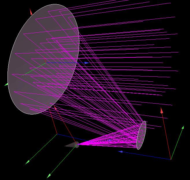
36 DVA-1 Ray Tracing Launch plane waves at reflector antenna (top of picture) Note caustic at prime focus due to shaping Reason for rays penetrating surface unknown 35
37 DVA-1 Beam Cuts 3 GHz 16 db feed taper E, D, and H planes plotted 36

38 DVA-1 Beam (±10 ) 37
39 Diffraction Effects Isak Theron has noted periodic variation in beam as a function of frequency Dirk de Villiers (Stellenbosch) [IEEE APS Symp. 2011] has analyzed this Diffraction from rim of secondary interferes with wavefront reflected by primary Analyze with GRASP Compare diffraction case with no diffraction plot difference Compare 16 db edge taper with 10 db Different optical configuration (larger) than de Villiers 38
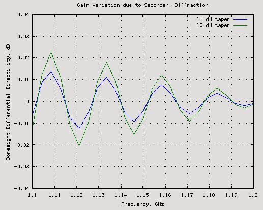
40 Diffraction Results 39
41 Timings Problem Time Symmetric: No Block 11 sec Central Blockage 18 sec Block + Struts 7:18 min DVA-1 Shaped Gregorian Offset 1:13 min Hardware 3 GHz dual-core Software GRASP (Win version) Running on linux using wine 40
42 Summary GRASP9 can be considered industry standard simulation SW Intended for solving optical problems at microwave frequencies Uses PO/PTD optical components many λ in size User specifies which couplings to calculate or include requires some user skill/knowledge to set up problem correctly Shown several examples symmetric reflector with scattering offset reflector with shaped reflecting surfaces but other capabilities not shown here 41
43 Where to Learn More Download free student version from Contains extensive documentation (2 books) Diaz & Milligan, Antenna Engineering Using Physical Optics, Artech House 1996 Has Matlab and Fortran code But check book review in IEEE Ant & Prop Magazine which lists errors Or contact me: 42
Modeling Antenna Beams
 Modeling Antenna Beams Walter Brisken National Radio Astronomy Observatory 2011 Sept 22 1 / 24 What to learn from this talk EM simulations of antennas can be complicated Many people have spent careers
A systematic approach to the analysis of polarisation-sensitive reflectors
 A systematic approach to the analysis of polarisation-sensitive reflectors Hans-Henrik Viskum TICRA Læderstræde 34, 2. DK-1201 Copenhagen K Denmark hhv@ticra.com ABSTRACT The analysis of a polarisation-sensitive
Empirical Parameterization of the Antenna Aperture Illumination Pattern
 Empirical Parameterization of the Antenna Aperture Illumination Pattern Preshanth Jagannathan UCT/NRAO Collaborators : Sanjay Bhatnagar, Walter Brisken Measurement Equation The measurement equation in
Development of Focal-Plane Arrays and Beamforming Networks at DRAO
 Development of Focal-Plane Arrays and Beamforming Networks at DRAO Bruce Veidt Dominion Radio Astrophysical Observatory Herzberg Institute of Astrophysics National Research Council of Canada Penticton,
Full-Wave and Multi-GTD Analysis of the Ice Cloud Imager for MetOp-SG
 Full-Wave and Multi-GTD Analysis of the Ice Cloud Imager for MetOp-SG Jakob Rosenkrantz de Lasson 1, Per Heighwood Nielsen 1, Cecilia Cappellin 1, David Marote Alvarez 2, Marc Bergada 2, Raquel Gonzalez
Ray Optics I. Last time, finished EM theory Looked at complex boundary problems TIR: Snell s law complex Metal mirrors: index complex
 Phys 531 Lecture 8 20 September 2005 Ray Optics I Last time, finished EM theory Looked at complex boundary problems TIR: Snell s law complex Metal mirrors: index complex Today shift gears, start applying
INTRODUCTION TO The Uniform Geometrical Theory of Diffraction
 INTRODUCTION TO The Uniform Geometrical Theory of Diffraction D.A. McNamara, C.W.I. Pistorius J.A.G. Malherbe University of Pretoria Artech House Boston London CONTENTS Preface xiii Chapter 1 The Nature
GRASP RELEASE NOTE
 GRASP9.4.01 RELEASE NOTE GRASP9.4.01 contains a large number of new features. Most notably, reflector surfaces can now be exported in CAD format and several program modules have been updated with support
> Compact range feed horns
 > Compact range feed horns ➊ TECHNICAL PERFORMANCES Rotationally symmetric radiation pattern Low cross polarization Stable amplitude taper with frequency Optimized refl ector edge and chamber wall illumination
ECE 5318/6352 Antenna Engineering. Dr. Stuart Long. Chapter 15. Reflector Antennas
 ECE 5318/6352 Antenna Engineering Dr. Stuart Long Chapter 15 Reflector Antennas 1 GEOMETRICAL CONFIGURATIONS large flat sheet small flat sheet (wide freq. range) corner reflector (narrow freq. range) parabolic
Background. Contents of this release note:
 Contents of this release note: Background Change for tabulated rims in GRASP9.8.02 Change of PO grid density control for advanced grid in GRASP9.8.02 Change of PO grid density control for tabulated_mesh
Simulation Advances. Antenna Applications
 Simulation Advances for RF, Microwave and Antenna Applications Presented by Martin Vogel, PhD Application Engineer 1 Overview Advanced Integrated Solver Technologies Finite Arrays with Domain Decomposition
BEST-FIT ADJUSTMENTS OF THE REFLECTORS IN A COMPACT RANGE 1
 Paper to be presented at Antenna Measurement Techniques Association 31 st Annual Symposium (AMTA 2009), Salt Lake City, Utah, USA, 1-6 November 2009. BEST-FIT ADJUSTMENTS OF THE REFLECTORS IN A COMPACT
HFSS PO Hybrid Region
 HFSS PO Hybrid Region Introduction The design of electrically large systems poses many challenges. Electromagnetic simulations can relatively quickly assess options and trade-offs before any physical testing.
Optical design of COrE+
 Optical design of COrE+ Karl Young November 23, 2015 The optical designs for COrE+ were made by Darragh McCarthy and Neil Trappe at Maynooth University and Karl Young and Shaul Hanany at University of
New Modelling Capabilities in Commercial Software for High-Gain Antennas
 6th European Conference on Antennas and Propagation (EUCAP) New Modelling Capabilities in Commercial Software for High-Gain Antennas Erik Jørgensen, Michael Lumholt, Peter Meincke, Min Zhou, Stig B. Sørensen,
Fundamentals of the Physical Theory of Diffraction
 Fundamentals of the Physical Theory of Diffraction Pyotr Ya. Ufimtsev BICCNTENNIAL f 1! 1807;! s JWILEY \» 2 0 0 7 ; ai Ir BICENTENNIAL WILEY-INTERSCIENCE A JOHN WILEY & SONS, INC., PUBLICATION Contents
Lecture 2: Introduction
 Lecture 2: Introduction v2015.0 Release ANSYS HFSS for Antenna Design 1 2015 ANSYS, Inc. Multiple Advanced Techniques Allow HFSS to Excel at a Wide Variety of Applications Platform Integration and RCS
Designing Horn Antenna utilizing FEM Symmetry Boundary Conditions
 Designing Horn Antenna utilizing FEM Symmetry Boundary Conditions If a structure has any symmetry (E or M i.e. Electric or Magnetic), the structure s physical size can be reduced symmetric plane boundary
Lecture Outline Chapter 26. Physics, 4 th Edition James S. Walker. Copyright 2010 Pearson Education, Inc.
 Lecture Outline Chapter 26 Physics, 4 th Edition James S. Walker Chapter 26 Geometrical Optics Units of Chapter 26 The Reflection of Light Forming Images with a Plane Mirror Spherical Mirrors Ray Tracing
Aspects of RF Simulation and Analysis Software Methods. David Carpenter. Remcom. B = t. D t. Remcom (Europe)
") Remcom (Europe) Central Boulevard Blythe Valley Park Solihull West Midlands England, B90 8AG www.remcom.com +44 870 351 7640 +44 870 351 7641 (fax) Aspects of RF Simulation and Analysis Software Methods
Remcom (Europe) Central Boulevard Blythe Valley Park Solihull West Midlands England, B90 8AG www.remcom.com +44 870 351 7640 +44 870 351 7641 (fax) Aspects of RF Simulation and Analysis Software Methods
OSKAR-2: Simulating data from the SKA
 OSKAR-2: Simulating data from the SKA AACal 2012, Amsterdam, 13 th July 2012 Fred Dulwich, Ben Mort, Stef Salvini 1 Overview OSKAR-2: Interferometer and beamforming simulator package. Intended for simulations
Simulation Advances for RF, Microwave and Antenna Applications
 Simulation Advances for RF, Microwave and Antenna Applications Bill McGinn Application Engineer 1 Overview Advanced Integrated Solver Technologies Finite Arrays with Domain Decomposition Hybrid solving:
ALMA Antenna responses in CASA imaging
 ALMA Antenna responses in CASA imaging Dirk Petry (ESO), December 2012 Outline Motivation ALBiUS/ESO work on CASA responses infrastructure and ALMA beam library First test results 1 Motivation ALMA covers
This tutorial illustrates how to use TracePro for the analysis of LCD Back Lights. The steps include:
 Requirements Models: None Properties: None Editions: TracePro Expert Introduction This tutorial illustrates how to use TracePro for the analysis of LCD Back Lights. The steps include: Generating a solid
Optics research for future receivers at NAOJ. Alvaro Gonzalez National Astronomical Observatory of Japan
 Optics research for future receivers at NAOJ Alvaro Gonzalez National Astronomical Observatory of Japan 1 Outline Follow up to presentations by: D. Iono, T. Kojima Optics for lower ALMA bands Band 1 (35
Phys 102 Lecture 17 Introduction to ray optics
 Phys 102 Lecture 17 Introduction to ray optics 1 Physics 102 lectures on light Light as a wave Lecture 15 EM waves Lecture 16 Polarization Lecture 22 & 23 Interference & diffraction Light as a ray Lecture
HFSS Hybrid Finite Element and Integral Equation Solver for Large Scale Electromagnetic Design and Simulation
 HFSS Hybrid Finite Element and Integral Equation Solver for Large Scale Electromagnetic Design and Simulation Laila Salman, PhD Technical Services Specialist laila.salman@ansys.com 1 Agenda Overview of
Chapter 26 Geometrical Optics
 Chapter 26 Geometrical Optics 1 Overview of Chapter 26 The Reflection of Light Forming Images with a Plane Mirror Spherical Mirrors Ray Tracing and the Mirror Equation The Refraction of Light Ray Tracing
OPTICS MIRRORS AND LENSES
 Downloaded from OPTICS MIRRORS AND LENSES 1. An object AB is kept in front of a concave mirror as shown in the figure. (i)complete the ray diagram showing the image formation of the object. (ii) How will
Phased Array Antennas with Optimized Element Patterns
 Phased Array Antennas with Optimized Element Patterns Sergei P. Skobelev ARTECH HOUSE BOSTON LONDON artechhouse.com Contents Preface Introduction xi xiii CHAPTER 1 General Concepts and Relations 1 1.1
Reflection and Refraction of Light
 PC1222 Fundamentals of Physics II Reflection and Refraction of Light 1 Objectives Investigate for reflection of rays from a plane surface, the dependence of the angle of reflection on the angle of incidence.
INVESTIGATIONS ON THE ANALYSIS AND DESIGN OF APERIODIC FREQUENCY SELECTIVE SURFACES FOR SPACE APPLICATIONS
 INVESTIGATIONS ON THE ANALYSIS AND DESIGN OF APERIODIC FREQUENCY SELECTIVE SURFACES FOR SPACE APPLICATIONS M. Zhou 1, S. B. Sørensen 1, N. Vesterdal 1, R. Dickie 2, R. Cahill 2, and G. Toso 3 1 TICRA,
Physics 202, Lecture 23
 Physics 202, Lecture 23 Today s Topics Lights and Laws of Geometric Optics Nature of Light Reflection and Refraction Law of Reflection Law of Refraction Index of Reflection, Snell s Law Total Internal
HFSS: Optimal Phased Array Modeling Using Domain Decomposition
 HFSS: Optimal Phased Array Modeling Using Domain Decomposition 15. 0 Release Authors: Dane Thompson Nick Hirth Irina Gordion Sara Louie Presenter: Dane Thompson Motivation Electronically scannable antenna
Efficient wave-optical calculation of 'bad systems'
 1 Efficient wave-optical calculation of 'bad systems' Norman G. Worku, 2 Prof. Herbert Gross 1,2 25.11.2016 (1) Fraunhofer Institute for Applied Optics and Precision Engineering IOF, Jena, Germany (2)
9. Polarization. 1) General observations [Room 310]
![9. Polarization. 1) General observations [Room 310]](/thumbs/74/70594885.jpg "9. Polarization. 1) General observations [Room 310]") 9. Polarization In this lab we are going to study the various phenomena related to the polarization of light. We will also learn how to analyze, control and transfer the polarization state of light. This
9. Polarization In this lab we are going to study the various phenomena related to the polarization of light. We will also learn how to analyze, control and transfer the polarization state of light. This
Chapter 15. Light Waves
 Chapter 15 Light Waves Chapter 15 is finished, but is not in camera-ready format. All diagrams are missing, but here are some excerpts from the text with omissions indicated by... After 15.1, read 15.2
Exercise 12 Geometrical and Technical Optics WS 2013/2014
 Exercise 12 Geometrical and Technical Optics WS 213/214 Slide projector and Köhler illumination In this exercise a simplified slide projector (or LCD projector) will be designed and simulated with ray
Stable Laser Resonator Modeling: Mesh Parameter Determination and Empty Cavity Modeling
 Stable Laser Resonator Modeling: Mesh Parameter Determination and Empty Cavity Modeling Justin Mansell, Steve Coy, Kavita Chand, Steve Rose, Morris Maynard, and Liyang Xu MZA Associates Corporation jmansell@mza.com
PHY132 Introduction to Physics II Class 5 Outline:
 PHY132 Introduction to Physics II Class 5 Outline: Ch. 22, sections 22.1-22.4 (Note we are skipping sections 22.5 and 22.6 in this course) Light and Optics Double-Slit Interference The Diffraction Grating
IMPLEMENTATION OF ANALYTICAL (MATLAB) AND NUMERICAL (HFSS) SOLUTIONS ADVANCED ELECTROMAGNETIC THEORY SOHAIB SAADAT AFRIDI HAMMAD BUTT ZUNNURAIN AHMAD
 AND NUMERICAL (HFSS) SOLUTIONS ADVANCED ELECTROMAGNETIC THEORY SOHAIB SAADAT AFRIDI HAMMAD BUTT ZUNNURAIN AHMAD") STUDY OF SCATTERING & RESULTANT RADIATION PATTERN: INFINITE LINE CURRENT SOURCE POSITIONED HORIZONTALLY OVER A PERFECTLY CONDUCTING INFINITE GROUND PLANE IMPLEMENTATION OF ANALYTICAL (MATLAB) AND NUMERICAL
STUDY OF SCATTERING & RESULTANT RADIATION PATTERN: INFINITE LINE CURRENT SOURCE POSITIONED HORIZONTALLY OVER A PERFECTLY CONDUCTING INFINITE GROUND PLANE IMPLEMENTATION OF ANALYTICAL (MATLAB) AND NUMERICAL
Comparison of TLM and FDTD Methods in RCS Estimation
 International Journal of Electrical Engineering. ISSN 0974-2158 Volume 4, Number 3 (2011), pp. 283-287 International Research Publication House http://www.irphouse.com Comparison of TLM and FDTD Methods
DEVIL PHYSICS THE BADDEST CLASS ON CAMPUS IB PHYSICS
 DEVIL PHYSICS THE BADDEST CLASS ON CAMPUS IB PHYSICS TSOKOS LESSON 9-2 SINGLE-SLIT DIFFRACTION Essential Idea: Single-slit diffraction occurs when a wave is incident upon a slit of approximately the same
E x Direction of Propagation. y B y
 x E x Direction of Propagation k z z y B y An electromagnetic wave is a travelling wave which has time varying electric and magnetic fields which are perpendicular to each other and the direction of propagation,
INTRODUCTION REFLECTION AND REFRACTION AT BOUNDARIES. Introduction. Reflection and refraction at boundaries. Reflection at a single surface
 Chapter 8 GEOMETRICAL OPTICS Introduction Reflection and refraction at boundaries. Reflection at a single surface Refraction at a single boundary Dispersion Summary INTRODUCTION It has been shown that
Chapter 38. Diffraction Patterns and Polarization
 Chapter 38 Diffraction Patterns and Polarization Diffraction Light of wavelength comparable to or larger than the width of a slit spreads out in all forward directions upon passing through the slit This
Contents Contents Creating a Simulation Example: A Dipole Antenna AMDS User s Guide
 Contents Contents 1 Creating a Simulation 7 Introduction 8 Data Files for Examples 8 Software Organization 9 Constructing the Geometry 10 Creating the Mesh 11 Defining Run Parameters 13 Requesting Results
PY212 Lecture 25. Prof. Tulika Bose 12/3/09. Interference and Diffraction. Fun Link: Diffraction with Ace Ventura
 PY212 Lecture 25 Interference and Diffraction Prof. Tulika Bose 12/3/09 Fun Link: Diffraction with Ace Ventura Summary from last time The wave theory of light is strengthened by the interference and diffraction
25-1 Interference from Two Sources
 25-1 Interference from Two Sources In this chapter, our focus will be on the wave behavior of light, and on how two or more light waves interfere. However, the same concepts apply to sound waves, and other
dq dt I = Irradiance or Light Intensity is Flux Φ per area A (W/m 2 ) Φ =
 Φ =") Radiometry (From Intro to Optics, Pedrotti -4) Radiometry is measurement of Emag radiation (light) Consider a small spherical source Total energy radiating from the body over some time is Q total Radiant
Radiometry (From Intro to Optics, Pedrotti -4) Radiometry is measurement of Emag radiation (light) Consider a small spherical source Total energy radiating from the body over some time is Q total Radiant
RCS Measurement and Analysis of Rectangular and Circular Cross-section Cavities
 RCS Measurement and Analysis of Rectangular and Circular Cross-section Cavities Abhinav Bharat, M L Meena, S. Sunil Kumar, Neha Sangwa, Shyam Rankawat Defence Laboratory, DRDO Jodhpur, India-342011 Abstract
Lecture Notes (Reflection & Mirrors)
") Lecture Notes (Reflection & Mirrors) Intro: - plane mirrors are flat, smooth surfaces from which light is reflected by regular reflection - light rays are reflected with equal angles of incidence and reflection
Lecture Notes (Reflection & Mirrors) Intro: - plane mirrors are flat, smooth surfaces from which light is reflected by regular reflection - light rays are reflected with equal angles of incidence and reflection
Design and Validation of Compact Antenna Test Ranges using Computational EM
 Design and Validation of Compact Antenna Test Ranges using Computational EM O. Borries, P. Meincke, E. Jørgensen, H.-H. Viskum, F. Jensen TICRA Copenhagen, Denmark ob@ticra.com C. H. Schmidt Airbus Defence
AP Physics: Curved Mirrors and Lenses
 The Ray Model of Light Light often travels in straight lines. We represent light using rays, which are straight lines emanating from an object. This is an idealization, but is very useful for geometric
High Frequency Wave Propagation and Discrete Geodesics
 High Frequency Wave Propagation and Discrete Geodesics Vladimir Oliker Department of Mathematics and Computer Science Emory University, Atlanta, Ga oliker@mathcs.emory.edu Workshop on High Frequency Wave
Chapter 36. Diffraction. Copyright 2014 John Wiley & Sons, Inc. All rights reserved.
 Chapter 36 Diffraction Copyright 36-1 Single-Slit Diffraction Learning Objectives 36.01 Describe the diffraction of light waves by a narrow opening and an edge, and also describe the resulting interference
Chapter 36. Image Formation
 Chapter 36 Image Formation Apr 22, 2012 Light from distant things We learn about a distant thing from the light it generates or redirects. The lenses in our eyes create images of objects our brains can
CHAPTER 6 MICROSTRIP RECTANGULAR PATCH ARRAY WITH FINITE GROUND PLANE EFFECTS
 107 CHAPTER 6 MICROSTRIP RECTANGULAR PATCH ARRAY WITH FINITE GROUND PLANE EFFECTS 6.1 INTRODUCTION The finite ground plane effects of microstrip antennas are one of the issues for the wireless mobile communication
f. (5.3.1) So, the higher frequency means the lower wavelength. Visible part of light spectrum covers the range of wavelengths from
 So, the higher frequency means the lower wavelength. Visible part of light spectrum covers the range of wavelengths from") Lecture 5-3 Interference and Diffraction of EM Waves During our previous lectures we have been talking about electromagnetic (EM) waves. As we know, harmonic waves of any type represent periodic process
Lecture 5-3 Interference and Diffraction of EM Waves During our previous lectures we have been talking about electromagnetic (EM) waves. As we know, harmonic waves of any type represent periodic process
Physics 1C, Summer 2011 (Session 1) Practice Midterm 2 (50+4 points) Solutions
 Practice Midterm 2 (50+4 points) Solutions") Physics 1C, Summer 2011 (Session 1) Practice Midterm 2 (50+4 points) s Problem 1 (5x2 = 10 points) Label the following statements as True or False, with a one- or two-sentence explanation for why you chose
Physics 1C, Summer 2011 (Session 1) Practice Midterm 2 (50+4 points) s Problem 1 (5x2 = 10 points) Label the following statements as True or False, with a one- or two-sentence explanation for why you chose
CHAPTER 26 INTERFERENCE AND DIFFRACTION
 CHAPTER 26 INTERFERENCE AND DIFFRACTION INTERFERENCE CONSTRUCTIVE DESTRUCTIVE YOUNG S EXPERIMENT THIN FILMS NEWTON S RINGS DIFFRACTION SINGLE SLIT MULTIPLE SLITS RESOLVING POWER 1 IN PHASE 180 0 OUT OF
Light and Mirrors MIRRORS
 Light and Mirrors MIRRORS 1 Polarized Sunglasses- How do they work? light waves vibrate in more than one plane light waves can be made to vibrate in a single plane by use of polarizing filters. 2 polarizing
Outline. Darren Wang ADS Momentum P2
 Outline Momentum Basics: Microstrip Meander Line Momentum RF Mode: RFIC Launch Designing with Momentum: Via Fed Patch Antenna Momentum Techniques: 3dB Splitter Look-alike Momentum Optimization: 3 GHz Band
Optical simulations within and beyond the paraxial limit
 Optical simulations within and beyond the paraxial limit Daniel Brown, Charlotte Bond and Andreas Freise University of Birmingham 1 Simulating realistic optics We need to know how to accurately calculate
Figure 1 - Refraction
 Geometrical optics Introduction Refraction When light crosses the interface between two media having different refractive indices (e.g. between water and air) a light ray will appear to change its direction
Lesson 1 Scattering, Diffraction, and Radiation
 Lesson 1 Scattering, Diffraction, and Radiation Chen-Bin Huang Department of Electrical Engineering Institute of Photonics Technologies National Tsing Hua University, Taiwan Various slides under courtesy
A Graphical User Interface (GUI) for Two-Dimensional Electromagnetic Scattering Problems
 for Two-Dimensional Electromagnetic Scattering Problems") A Graphical User Interface (GUI) for Two-Dimensional Electromagnetic Scattering Problems Veysel Demir vdemir@olemiss.edu Mohamed Al Sharkawy malshark@olemiss.edu Atef Z. Elsherbeni atef@olemiss.edu Abstract
A Graphical User Interface (GUI) for Two-Dimensional Electromagnetic Scattering Problems Veysel Demir vdemir@olemiss.edu Mohamed Al Sharkawy malshark@olemiss.edu Atef Z. Elsherbeni atef@olemiss.edu Abstract
25 The vibration spiral
 25 The vibration spiral Contents 25.1 The vibration spiral 25.1.1 Zone Plates............................... 10 25.1.2 Circular obstacle and Poisson spot.................. 13 Keywords: Fresnel Diffraction,
Topic 9: Wave phenomena - AHL 9.2 Single-slit diffraction
 Topic 9.2 is an extension of Topic 4.4. Both single and the double-slit diffraction were considered in 4.4. Essential idea: Single-slit diffraction occurs when a wave is incident upon a slit of approximately
THE growing number of sensor and communication systems
 2858 IEEE TRANSACTIONS ON ANTENNAS AND PROPAGATION, VOL. 53, NO. 9, SEPTEMBER 2005 Interleaved Thinned Linear Arrays Randy L. Haupt, Fellow, IEEE Abstract This paper presents three approaches to improving
Chapter 18 Ray Optics
 Chapter 18 Ray Optics Chapter Goal: To understand and apply the ray model of light. Slide 18-1 Chapter 18 Preview Looking Ahead Text p. 565 Slide 18-2 Wavefronts and Rays When visible light or other electromagnetic
Chapter 36. Diffraction. Dr. Armen Kocharian
 Chapter 36 Diffraction Dr. Armen Kocharian Diffraction Light of wavelength comparable to or larger than the width of a slit spreads out in all forward directions upon passing through the slit This phenomena
A MATLAB PHYSICAL OPTICS RCS PREDICTION CODE
 A MATLAB PHYSICAL OPTICS RCS PREDICTION CODE Elmo E. Garrido, Jr. and David C. Jenn Naval Postgraduate School Monterey, CA 93943 SUMMARY POFACETS is an implementation of the physical optics approximation
PHYSICS. Chapter 33 Lecture FOR SCIENTISTS AND ENGINEERS A STRATEGIC APPROACH 4/E RANDALL D. KNIGHT
 PHYSICS FOR SCIENTISTS AND ENGINEERS A STRATEGIC APPROACH 4/E Chapter 33 Lecture RANDALL D. KNIGHT Chapter 33 Wave Optics IN THIS CHAPTER, you will learn about and apply the wave model of light. Slide
Diffraction and Interference of Plane Light Waves
 1 Diffraction and Interference of Plane Light Waves Introduction In this experiment you will become familiar with diffraction patterns created when a beam of light scatters from objects placed in its path.
HFSS 14 Update for SI and RF Applications Markus Kopp Product Manager, Electronics ANSYS, Inc.
 HFSS 14 Update for SI and RF Applications Markus Kopp Product Manager, Electronics ANSYS, Inc. 1 ANSYS, Inc. September 21, Advanced Solvers: Finite Arrays with DDM 2 ANSYS, Inc. September 21, Finite Arrays
Experiment 8 Wave Optics
 Physics 263 Experiment 8 Wave Optics In this laboratory, we will perform two experiments on wave optics. 1 Double Slit Interference In two-slit interference, light falls on an opaque screen with two closely
Physics 1202: Lecture 17 Today s Agenda
 Physics 1202: Lecture 17 Today s Agenda Announcements: Team problems today Team 10, 11 & 12: this Thursday Homework #8: due Friday Midterm 2: Tuesday April 10 Office hours if needed (M-2:30-3:30 or TH
specular diffuse reflection.
 Lesson 8 Light and Optics The Nature of Light Properties of Light: Reflection Refraction Interference Diffraction Polarization Dispersion and Prisms Total Internal Reflection Huygens s Principle The Nature
POS RELEASE NOTE
 POS5.3.01 RELEASE NOTE POS5.3.01 introduces support for parallel computing on Linux clusters as well as several bug fixes. The Linux-cluster version of POS5 is available at no additional costs for all
Powerful features (1)
") HFSS Overview Powerful features (1) Tangential Vector Finite Elements Provides only correct physical solutions with no spurious modes Transfinite Element Method Adaptive Meshing r E = t E γ i i ( x, y,
HFSS Overview Powerful features (1) Tangential Vector Finite Elements Provides only correct physical solutions with no spurious modes Transfinite Element Method Adaptive Meshing r E = t E γ i i ( x, y,
Class 11 Introduction to Surface BRDF and Atmospheric Scattering. Class 12/13 - Measurements of Surface BRDF and Atmospheric Scattering
 University of Maryland Baltimore County - UMBC Phys650 - Special Topics in Experimental Atmospheric Physics (Spring 2009) J. V. Martins and M. H. Tabacniks http://userpages.umbc.edu/~martins/phys650/ Class
Lecture 7: Introduction to HFSS-IE
 Lecture 7: Introduction to HFSS-IE 2015.0 Release ANSYS HFSS for Antenna Design 1 2015 ANSYS, Inc. HFSS-IE: Integral Equation Solver Introduction HFSS-IE: Technology An Integral Equation solver technology
Contrast Optimization: A faster and better technique for optimizing on MTF ABSTRACT Keywords: INTRODUCTION THEORY
 Contrast Optimization: A faster and better technique for optimizing on MTF Ken Moore, Erin Elliott, Mark Nicholson, Chris Normanshire, Shawn Gay, Jade Aiona Zemax, LLC ABSTRACT Our new Contrast Optimization
Introduction to the FEKO Suite
 Introduction to the FEKO Suite FEKO is a suite of tools that is used for electromagnetic field analysis of 3D structures. It offers several state-of-the-art numerical methods for the solution of Maxwell
Lecture Outlines Chapter 26
 Lecture Outlines Chapter 26 11/18/2013 2 Chapter 26 Geometrical Optics Objectives: After completing this module, you should be able to: Explain and discuss with diagrams, reflection and refraction of light
Shadows in the graphics pipeline
 Shadows in the graphics pipeline Steve Marschner Cornell University CS 569 Spring 2008, 19 February There are a number of visual cues that help let the viewer know about the 3D relationships between objects
Rectangular Lenslet Array
 Rectangular Lenslet Array INTRODUCTION Lenslet arrays are used in a variety of applications that include beam homogenization. This knowledge base article demonstrates the setup of an imaging lenslet array
ANALYSIS OF COMPACT RANGE REFLECTORS WITH SERRATED EDGES
 ANALYSIS OF COMPACT RANGE REFLECTORS WITH SERRATED EDGES Kevin Miller and Dr. R. W. Kreutel Abstract The use of serrated edge treatment in the design of a compact range collimating reflector is one method
Physics 4C Chabot College Scott Hildreth
 Physics 4C Chabot College Scott Hildreth Snell s Law with Microwave Optics Experiment Goals: Experimentally verify Snell s Law holds for microwaves. Lab Safety Note! Although the microwaves in this experiment
Gaussian Beam Calculator for Creating Coherent Sources
 Gaussian Beam Calculator for Creating Coherent Sources INTRODUCTION Coherent sources are represented in FRED using a superposition of Gaussian beamlets. The ray grid spacing of the source is used to determine
Physics 202 Homework 9
 Physics 202 Homework 9 May 29, 2013 1. A sheet that is made of plastic (n = 1.60) covers one slit of a double slit 488 nm (see Figure 1). When the double slit is illuminated by monochromatic light (wavelength
High dynamic range imaging, computing & I/O load
 High dynamic range imaging, computing & I/O load RMS ~15µJy/beam RMS ~1µJy/beam S. Bhatnagar NRAO, Socorro Parameterized Measurement Equation Generalized Measurement Equation Obs [ S M V ij = J ij, t W
FRED Slit Diffraction Application Note
 FRED Slit Diffraction Application Note The classic problem of diffraction through a slit finds one of its chief applications in spectrometers. The wave nature of these phenomena can be modeled quite accurately
3. Image formation, Fourier analysis and CTF theory. Paula da Fonseca
 3. Image formation, Fourier analysis and CTF theory Paula da Fonseca EM course 2017 - Agenda - Overview of: Introduction to Fourier analysis o o o o Sine waves Fourier transform (simple examples of 1D
3 - SYNTHETIC APERTURE RADAR (SAR) SUMMARY David Sandwell, SIO 239, January, 2008
 SUMMARY David Sandwell, SIO 239, January, 2008") 1 3 - SYNTHETIC APERTURE RADAR (SAR) SUMMARY David Sandwell, SIO 239, January, 2008 Fraunhoffer diffraction To understand why a synthetic aperture in needed for microwave remote sensing from orbital altitude
1 3 - SYNTHETIC APERTURE RADAR (SAR) SUMMARY David Sandwell, SIO 239, January, 2008 Fraunhoffer diffraction To understand why a synthetic aperture in needed for microwave remote sensing from orbital altitude
Diffraction and Interference Lab 7 PRECAUTION
 HB 11-14-07 Diffraction and Interference Lab 7 1 Diffraction and Interference Lab 7 Equipment laser, eye goggles, optical bench, slide holder, slide with 4 single slits, slide with 4 double slits, 11X14
Single slit diffraction
 Single slit diffraction Book page 364-367 Review double slit Core Assume paths of the two rays are parallel This is a good assumption if D >>> d PD = R 2 R 1 = dsin θ since sin θ = PD d Constructive interference
Supplementary Figure 1 Optimum transmissive mask design for shaping an incident light to a desired
 Supplementary Figure 1 Optimum transmissive mask design for shaping an incident light to a desired tangential form. (a) The light from the sources and scatterers in the half space (1) passes through the