Unique Features of the GE Senoclaire Tomosynthesis System. Tyler Fisher, M.S., DABR Therapy Physics, Inc.
|
|
|
- Milton Holt
- 6 years ago
- Views:
Transcription
1 Unique Features of the GE Senoclaire Tomosynthesis System Tyler Fisher, M.S., DABR Therapy Physics, Inc.
2 Conflict of Interest Disclosure I have no conflicts to disclose.
3 Learning Objectives Overview of GE SenoClaire System Medical Physicist QC Testing Requirements Common Pit Falls, Errors, and Issues Technologist QC Testing Requirements Review the FDA DBT Certificate Extension Program Note: This presentation assumes the physicist is proficient with 2D GE Physics Testing Procedures

4
5 SenoClaire System Summary Uses same Target/Filter combinations as 2D system. Similar Dose level in 3D as 2D FDA Approved for Screening as 2D CC and 3D MLO views. An exam consisting of one DBT MLO view plus one 2D CC view is clinically noninferior to a standard two view digital mammography examination as measured by the area under the receiver operating characteristic (ROC) curve 1 Available as an add on for all Senographe Essential systems currently installed. V Preview reconstruction option synthesized 2D image from 3D acquisition 1. SenoClaire GE Breast Tomosynthesis Clinical and Non Clinical Information, EN, Rev. 1, Page 7
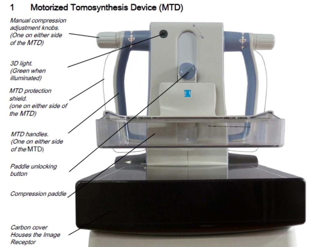
6 SenoClaire Attachment 3 Available Paddles 24 x 31, Elevated 24 x 31, Sliding 19 x 23 9 images acquired over a 25 0 sweep. Step and Shoot Acquisition 100 micron pixel size no binning of pixels 5:1 Anti Scatter grid MTD attachment weighs over 12 kg and is not counterbalanced use caution if manually moving. Not available for Magnification, CESM, or negative angle exposures.
7


8 Installing the MTD
9 Caution! When installing and removing the MTD, proper care must be taken not to scratch, dent, or damage BOTH the Digital Detector and the MTD grid. The Cart that holds the MTD when not in use is helpful for initially placing the weight of the MTD on the Digital Detector, but should be removed before final alignment. Especially when removing the MTD, make sure that the MTD is clear of the guiderails before lowering the gantry out of the way. It is possible to shear the guiderails if the MTD is attached to the cart and the gantry is lowered prematurely.

10


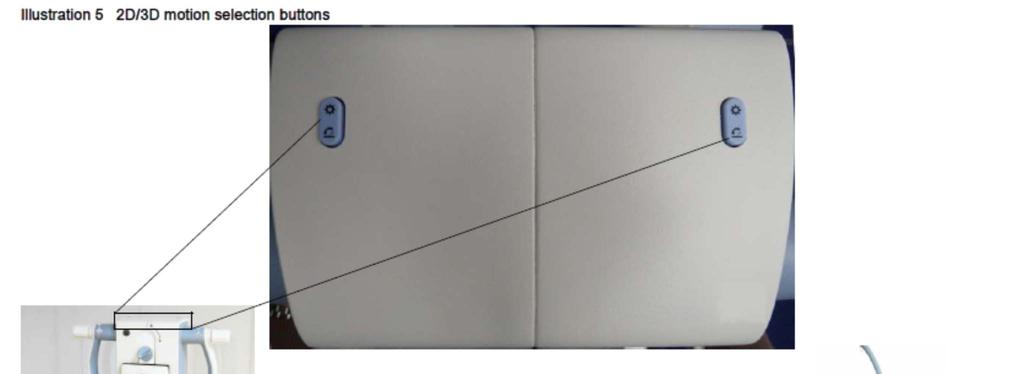
11 Performing a 3D Acquisition Initialize 3D mode by pressing motion selection button on MTD until 3D light is illuminated. Move Tube Head into start position using the Gantry Arm Movement Control Buttons Select Right or Left Laterality at Control Console From patient s perspective, Gantry starting to the left must be a Right Laterality acquisition. Gantry starting on the right must be a Left Laterality acquisition. Press Foot Pedal, Prep, and Expose Buttons. Following completion of 3D acquisition, gantry is not ready for a second. Must manually move gantry into position again.
12 Image Processing Images are processed at Dr s Review Workstation using GE s Adaptive Statistical Iterative Reconstruction (ASiR) system. Images should be Automatically Pushed to Review Workstation for Reconstruction. At acceptance, remind service that this must be functional for you to complete the testing. Both slabs (10 mm) and planes (0.5 mm or 1 mm) are reconstructed. Technologist Control Station only sees 9 acquired images to review positioning. For submission to FDA, must submit a slice of the phantom showing best score (usually at 37 mm or 38 mm) from the Review Workstation. Image must have identifying data on it (kvp, ma, Unit Name, Type of Acquisition) Important to remind service that you will need a way to print or burn the image from the Review Workstation.
13 Medical Physicist QC Tests QAP (Quality Assurance Procedures) CNR and MTF Measurement with MTD Flat Field 3D Test Grid Texture Test AOP 2D and SNR Check with MTD AOP 3D Check Non QAP Phantom IQ Test with MTD Phantom IQ 3D Test Compression Paddle Border to Chest Wall Alignment with MTD Breast Entrance Exposure and Average Glandular Dose with MTD Breast Entrance Exposure and Average Glandular Dose in 3D Mode Artifact Evaluation and Flat Field Uniformity with MTD Volume Coverage

14 Many of the QAP tests are nearly identical to 2D tests, but with MTD system in place. Browser QAP Button MTD Flat Field 3D Test CNR and MTF Measurement with MTD 2D AOP and SNR Check with MTD
15 Grid Texture Test Objective: To measure the amount of grid texture in 2D Images. Necessary due to differences in grid texture of MTD device compared to gain calibration of traditional system. Uses 25 mm thick flat field phantom. Acquire 10 images. Record Result. Action Limit: Texture Level must not exceed If this fails, try re installing the MTD and performing the test again.


16 Grid Texture Test Measured times the allowable Obvious gridlines in flat field image Corrected by service with new Gain Calibration In this case, I did not allow facility to perform 3D imaging until issue was corrected.
17 AOP 3D Check Verifies that Correct Parameters are Selected in AOP 3D Mode Uses 25 mm, 50 mm, and 60 mm acrylic plates. No SNR Measurement as with 2D. Acrylic Thickness (mm) Exposure Parameters For AOP 3D Mode Only Track/Filter mas kv 25 Mo/Mo or Mo/Rh Rh/Rh Rh/Rh or 31
18 Phantom IQ Test with MTD Identical to 2D Phantom IQ Test but with MTD system in place. Rh/Rh, 29 kvp, 56 mas Action Limit: 4 fibers, 3 speck groups, 3 masses.
19 Phantom IQ 3D Test Set system to acquire 3D acquisition Manual Technique: Rh/Rh, 29 kvp, 56 mas Review Reconstructed Image on Dr. s Review Workstation View both slabs and planes. Select plane image with best score for submission to FDA Action Limit: 4 fibers, 3 speck groups, 3 masses.
20

21
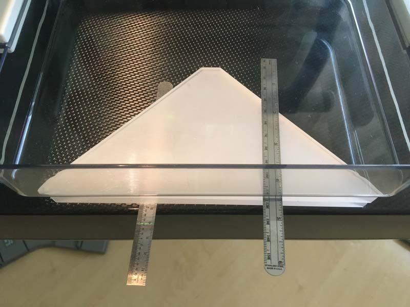
22 Compression Paddle Border to Chest Wall Alignment Test with MTD Objective: To assure the paddle chest wall side border aligns with the chest wall side of the detector. Both Mo and Rh targets must be tested. Must perform test with all 3 paddles (if used clinically) 24 x 31 paddle Elevated 24 x 31 paddle Sliding 19 x 23 paddle FDA requires that you follow the test procedure as specified in the QC manual or show that your procedure is not significantly different. Show your work

23 Compression Paddle Border to Chest Wall Alignment Test with MTD Coin must be as close as possible, but inside of the tangent to the inner vertical surface of the compression paddle. Recommend taping coin on top of compression paddle as close to chest wall edge as possible. Without tape, coin will slide away from chest wall edge.


24 Compression Paddle Border to Chest Wall Alignment Test with MTD Set the paddle to approximately 4.2 cm above the breast support. There are 2 possible geometric cases for the coin:
 Calculate Zd = Z d * 1.063 Action Limit: Zd must be < 6.6 mm. Enter Results in Table")
25 Compression Paddle Border to Chest Wall Alignment Test with MTD Use segment tool to measure Full Diameter (Wd) & Partial Diameter (Pd) Note the segment tool measures in a plane 2 cm above breast support Calculate Alignment Deviation Z d = (Wd Pd) Calculate Zd = Z d * Action Limit: Zd must be < 6.6 mm. Enter Results in Table
26 Breast Entrance Exposure and Average Glandular Dose with MTD Measure in AOP mode (STD, CNT, & Dose) Rotate Phantom from Normal Orientation. **Verify CNT Dose Setting with MTD**
27 3D Breast Entrance Exposure and Average Glandular Dose Perform a 3D Stationary Acquisition AOP Mode or Manual Rh/Rh, 29 kvp, 45 mas Rotate Phantom from Normal Orientation.
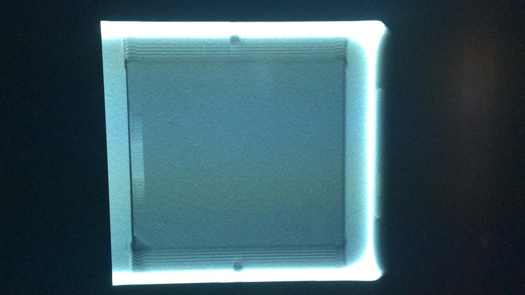
28 Artifact Evaluation and Flat Field Uniformity with MTD Objective: To assess the degree and source of artifacts and to assure that the Flat Field image is Uniform. 2D Acquisition in Mo/Mo, Mo/Rh, and Rh/Rh modes. Review Raw Images from Browser There is a separate Gain Calibration for the MTD to create uniform images.
29 Volume Coverage Objective: To ensure that the entire imaged object is reconstructed on the Z Axis. 3D Acquisition with 25 mm & 60 mm phantoms with aluminum sheets above and below. Manual Exposure Technique: 25 mm: Mo/Mo, 26 kvp, 45 mas 60 mm: Rh/Rh, 29, kvp, 110 mas Visually Verify that the top and bottom Al sheets are visible in the reconstructed volume.

30 Volume Coverage

31 Volume Coverage


32
33 Summary of Physics Tests Test Pass/Fail Criteria Timeframe to Correct Phantom IQ Test with MTD 4 Fibers, 3 Speck Groups, 3 Masses Immediate CNR and MTF Measurement with MTD MTF at 2 lp/mm > 49% MTF at 4 lp/mm > 18% Change in CNR < 0.20 Immediate Flat Field 3D Test Brightness Non Uniformity and SNR Non Uniformity Must Pass Immediate Phantom IQ 3D Test 4 Fibers, 3 Speck Groups, 3 Masses Immediate Grid Texture Test Texture Level < Days (Use Discretion) AOP 2D and SNR Check with MTD Exposure Parameters within Limits SNR > 50 Immediate AOP 3D Check Exposure Parameters within Limits Immediate
34 Summary of Physics Tests Test Pass/Fail Criteria Timeframe to Correct Compression Paddle Border to Chest Wall Alignment with MTD Chest Wall edge of Paddle Not in Image Chest Wall edge < 6.6 mm beyond detector 30 Days Breast Entrance Exposure and Average Glandular Dose with MTD 3 mgy (300 mrad) Immediate Breast Entrance Exposure and Average Glandular Dose in 3D Mode 3 mgy (300 mrad) Immediate Artifact Evaluation and Flat Field Uniformity with MTD No Artifact or Non Uniformity that is expected to mimic or obscure clinical information 30 Days (Use Discretion) Volume Coverage Focal Plane of Top and Bottom Al sheets visible within the reconstructed volume Immediate
35 Technologist QC Tests Minimum Frequency Weekly Monthly Semi Annually Procedure Phantom IQ Test with MTD CNR and MTF Measurement with MTD Flat Field 3D Test Phantom IQ 3D Test Grid Texture Test AOP 2D and SNR Check with MTD AOP 3D Check Visual Checklist Compression Force Test All 2D QC TESTS MUST STILL BE PERFORMED! These tests are in addition to the routine GE QC
36 FDA DBT Certificate Extension Program Under MQSA each Manufacturer s DBT system is considered a new modality, and the personnel training requirements apply. The certificate extension program only applies to the DBT portion of the system. The 2D portion of the system must be accredited by one of the approved accreditation bodies. The facility must have the approval of the FDA prior to DBT clinical use.

37 FDA DBT Application Process Available at: EmittingProducts/MammographyQuality StandardsActandProgram/FacilityCertificationandInspection/ucm htm Includes Facility Information, Unit ID, Image Receptor ID, Monitor ID, Personnel Qualifications. 3D Phantom Image (Hardcopy or Softcopy) Include the Complete, Detailed Mammography Equipment Evaluation Include an Evaluation of the DBT Manufacturer s QC Program
38 FDA DBT Certificate Extension Submission Send All Application Materials to: FFDM and DBT Certification Extension Program Division of Mammography Quality Standards FDA/CDRH/OIR New Hampshire Ave., WO Silver Spring, MD Phone: Fax:
39 In order to acquire the DBT image set, the GE system uses views over sweep angle of degrees? 20% 20% 20% 20% 20% views, 25 degrees 2. 9 views, 25 degrees views, 15 degrees views, 15 degrees 5. 9 views, 15 degrees 10
40 In order to acquire the DBT image set, the GE system uses views over sweep angle of degrees? views, 25 degrees 2. 9 views, 25 degrees views, 15 degrees views, 15 degrees 5. 9 views, 15 degrees Reference: GE Breast Tomosynthesis Operator Manual, EN, Revision 1. Page #24.
41 What is the minimum acceptable phantom score for the 3D image? 20% 20% 20% 20% 20% 1. 5 Fibers, 4 Speck Groups, 4 Masses 2. 4 Fibers, 4 Speck Groups, 4 Masses 3. 4 Fibers, 4 Speck Groups, 3 Masses 4. 4 Fibers, 3 Speck Groups, 3 Masses 5. 3 Fibers, 3 Speck Groups, 3 Masses 10
42 What is minimum acceptable phantom score for the 3D image? 1. 5 Fibers, 4 Speck Groups, 4 Masses 2. 4 Fibers, 4 Speck Groups, 4 Masses 3. 4 Fibers, 4 Speck Groups, 3 Masses 4. 4 Fibers, 3 Speck Groups, 3 Masses 5. 3 Fibers, 3 Speck Groups, 3 Masses Reference: GE Breast Tomosynthesis Quality Control Manual, EN, Revision 1. Page #21.
43 What is the Grid Ratio for the Anti Scatter grid? 20% 20% 20% 20% 20% 1. 2:1 2. 4:1 3. 5:1 4. 8: :1 10
44 What is the Grid Ratio for the Anti Scatter grid? 1. 2:1 2. 4:1 3. 5:1 4. 8: :1 Reference: GE Breast Tomosynthesis Operator Manual, EN, Revision 1. Page #198.
Certificate Extension II 8/1/2016. Certification Extension Process for Digital Breast Tomosynthesis and Medical Physicists Role
 Certification Extension Process for Digital Breast Tomosynthesis and Medical Physicists Role Kish Chakrabarti, Ph.D., FAAPM Division of Mammography Quality Standards Center for Devices and Radiological
RECENTLY APPROVED GE FFDM DBT TESTING PROCEDURES.
 RECENTLY APPROVED GE FFDM DBT TESTING PROCEDURES. S. G U R U P R A S A D, P H. D., D A B R, E M E R I T U S, M AT H E W H A L L M. S. N O RT H S H O R E U N I V E R S I T Y H E A LT H S Y S T E M A N D
8/2/2016. Hands-on GE SenoClaire DBT: technical characteristics & quality control. Disclosures and Acknowledgements
 Hands-on GE SenoClaire DBT: technical characteristics & quality control Razvan Iordache, Ph.D. GE Healthcare Imagination at work Disclosures and Acknowledgements Razvan Iordache Employee of GE Healthcare
Lorad FFDM QC Procedures for Medical Physicist. Tao Wu, Ph.D. Hologic, Inc.
 Lorad FFDM QC Procedures for Medical Physicist Tao Wu, Ph.D. Hologic, Inc. Lorad Selenia FFDM Tests Following Lorad QC Manual Collimation Assessment Artifact Evaluation System Resolution Phantom Image
ACMP 25th Annual Meeting
 Surveying and QC of Stereotactic Breast Biopsy Units for ACR Accreditation ACMP 25th Annual Meeting Seattle, WA May 3, 2008 Melissa C. Martin, M.S., FACR Therapy Physics, Inc. 879 West 190th St., Ste 419,
4/19/2016. Deborah Thames R.T. (R)(M)(QM) Theory & Technology and advancement in 3D imaging DBT
(M)(QM) Theory & Technology and advancement in 3D imaging DBT") Deborah Thames R.T. (R)(M)(QM) Theory & Technology and advancement in 3D imaging DBT 1 Three manufacturers approved for Tomo Hologic and GE, and Siemens Why 2D Digital Mammography 2D FFDM it appears to
Deborah Thames R.T. (R)(M)(QM) Theory & Technology and advancement in 3D imaging DBT 1 Three manufacturers approved for Tomo Hologic and GE, and Siemens Why 2D Digital Mammography 2D FFDM it appears to
Z-MOTION. Universal Digital Radiographic System Z-MOTION. Control-X Medical CONTROL-X MEDICAL
 Control-X Medical Z-MOTION Compact design, low ceiling height requirement Motorized and manual movement capability Wide motion / SID range Best-in-class image quality Flexible connectivity to PACS systems
10/9/2018. Deborah Thames BSRS RT (R)(M)(QM) Theory & Technology and advancement in 3D imaging DBT
(M)(QM) Theory & Technology and advancement in 3D imaging DBT") Deborah Thames BSRS RT (R)(M)(QM) Theory & Technology and advancement in 3D imaging DBT 1 Mammography Five FFDM approved for Tomo Hologic, Ge Senoclair and GE Pristina, Siemens, and Fujifilm 2 Why 2D Digital
Deborah Thames BSRS RT (R)(M)(QM) Theory & Technology and advancement in 3D imaging DBT 1 Mammography Five FFDM approved for Tomo Hologic, Ge Senoclair and GE Pristina, Siemens, and Fujifilm 2 Why 2D Digital
Assessment of 3D performance metrics. X-ray based Volumetric imaging systems: Fourier-based imaging metrics. The MTF in CT
 Assessment of 3D performance metrics D and 3D Metrics of Performance Towards Quality Index: Volumetric imaging systems X-ray based Volumetric imaging systems: CBCT/CT Tomosynthesis Samuel Richard and Ehsan
Acknowledgments and financial disclosure
 AAPM 2012 Annual Meeting Digital breast tomosynthesis: basic understanding of physics principles James T. Dobbins III, Ph.D., FAAPM Director, Medical Physics Graduate Program Ravin Advanced Imaging Laboratories
Design Considerations in Optimizing a Breast Tomosynthesis System
 Design Considerations in Optimizing a Breast Tomosynthesis System Andrew Smith, Ph.D., Vice President - Imaging Science, Hologic Introduction Breast tomosynthesis, also referred to as three-dimensional
Design and performance characteristics of a Cone Beam CT system for Leksell Gamma Knife Icon
 Design and performance characteristics of a Cone Beam CT system for Leksell Gamma Knife Icon WHITE PAPER Introduction Introducing an image guidance system based on Cone Beam CT (CBCT) and a mask immobilization
MEDICAL EQUIPMENT: COMPUTED TOMOGRAPHY. Prof. Yasser Mostafa Kadah
 MEDICAL EQUIPMENT: COMPUTED TOMOGRAPHY Prof. Yasser Mostafa Kadah www.k-space.org Recommended Textbook X-Ray Computed Tomography in Biomedical Engineering, by Robert Cierniak, Springer, 211 Computed Tomography
Quality control phantoms and protocol for a tomography system
 Quality control phantoms and protocol for a tomography system Lucía Franco 1 1 CT AIMEN, C/Relva 27A O Porriño Pontevedra, Spain, lfranco@aimen.es Abstract Tomography systems for non-destructive testing
Fujifilm DR Solution. FDR AcSelerate. The new pinnacle in diagnostic imaging from Fujifilm ISS. CsI. Dynamic Visualization. Technology.
 Fujifilm DR Solution FDR AcSelerate The new pinnacle in diagnostic imaging from Fujifilm CsI Scintillator ISS Technology Dynamic Visualization Welcome to the X-ray room of the future! A streamlined solution
연구용유방초음파질관리 원광대학병원김혜원
 연구용유방초음파질관리 원광대학병원김혜원 Why US QC? Quality control (QC) testing of ultrasound scanners is important to verify the proper and consistent operation of these devices. main goal ; quality improvement Guidelines
ENGLISH. Digital Breast Tomosynthesis
 ENGLISH Digital Breast Tomosynthesis Medical imaging excellence Planmed is strongly committed to improving the early detection of breast cancer. Our mission is to provide top quality imaging systems for
Digital Breast Tomosynthesis: The Fundamentals
 Digital Breast Tomosynthesis: The Fundamentals 8:00 am Registration and Coffee 8:30 am Introduction What is DBT? Why do we need DBT? How does DBT work? Clinical issues Clinical advantages 10:10 am Informal
CT Protocol Review: Practical Tips for the Imaging Physicist Physicist
 CT Protocol Review: Practical Tips for the Imaging Physicist Physicist Dianna Cody, Ph.D., DABR, FAAPM U.T.M.D. Anderson Cancer Center August 8, 2013 AAPM Annual Meeting Goals Understand purpose and importance
Optimisation of Toshiba Aquilion ONE Volume Imaging
 Optimisation of Toshiba Aquilion ONE Volume Imaging Jane Edwards, RPRSG Royal Free London NHS Foundation Trust Dr Mufudzi Maviki, Plymouth Hospitals NHS Trust Background In 2011/12 Radiology at RFH was
DISC QA Mamchex Tool Use Instructions with CARESTREAM DIRECTVIEW CR Mammography Systems
 DISC QA Mamchex Tool Use Instructions with CARESTREAM DIRECTVIEW CR Mammography Systems Purpose This document describes and provides instructions for use of the QA Mamchex Tool in calibrating a mammography
SUMMARY OF DENTAL MEASUREMENT PROCEDURES (Abridged Protocol)
") SUMMARY OF DENTAL MEASUREMENT PROCEDURES (Abridged Protocol) INTRAORAL IMAGING PROCEDURE Entrance Skin Exposure / Air Kerma To measure the typical intraoral Entrance Skin Exposure (ESE) and Entrance Skin
SUMMARY OF DENTAL MEASUREMENT PROCEDURES (Abridged Protocol) INTRAORAL IMAGING PROCEDURE Entrance Skin Exposure / Air Kerma To measure the typical intraoral Entrance Skin Exposure (ESE) and Entrance Skin
3/27/2012 WHY SPECT / CT? SPECT / CT Basic Principles. Advantages of SPECT. Advantages of CT. Dr John C. Dickson, Principal Physicist UCLH
 3/27/212 Advantages of SPECT SPECT / CT Basic Principles Dr John C. Dickson, Principal Physicist UCLH Institute of Nuclear Medicine, University College London Hospitals and University College London john.dickson@uclh.nhs.uk
AAPM Standard of Practice: CT Protocol Review Physicist
 AAPM Standard of Practice: CT Protocol Review Physicist Dianna Cody, Ph.D., DABR, FAAPM U.T.M.D. Anderson Cancer Center September 11, 2014 2014 Texas Radiation Regulatory Conference Goals Understand purpose
Fits you like no other
 Fits you like no other BrightView X and XCT specifications The new BrightView X system is a fully featured variableangle camera that is field-upgradeable to BrightView XCT without any increase in room
Chapter 1 General Information
 Chapter 1 General Information System Description Chapter 1 General Information 1.0 System Description The Affirm attaches to the Selenia Dimensions. A biopsy device attaches to the Affirm. X- and Y-axes
AIDR 3D Iterative Reconstruction:
 Iterative Reconstruction: Integrated, Automated and Adaptive Dose Reduction Erin Angel, PhD Manager, Clinical Sciences, CT Canon Medical Systems USA Iterative Reconstruction 1 Since the introduction of
DX-D 300. Flexible Direct Radiography System
 DX-D 300 Flexible Direct Radiography System MUSICA² processing provides outstanding contrast detail and consistently excellent image quality Universal, flexible and affordable modality combines a single
DX-D 100 with wireless detector
 M O B I L E D R S O L U T I O N DX-D 100 with wireless detector Patients who most need imaging exams may lack the mobility necessary to move to the X-ray room or to position themselves properly for optimum
product data Raybow dr mobile digital radiographic system with wireless detector product data
 Raybow dr mobile digital radiographic system with wireless detector Integrating all the advanced technologies, the ergonomic and high quality system Raybow dr lets you perform digital radiographies anywhere:
Fits you like no other
 Fits you like no other Philips BrightView X and XCT specifications The new BrightView X system is a fully featured variableangle camera that is field-upgradeable to BrightView XCT without any increase
Digital Scatter Removal in Mammography to enable Patient Dose Reduction
 Digital Scatter Removal in Mammography to enable Patient Dose Reduction Mary Cocker Radiation Physics and Protection Oxford University Hospitals NHS Trust Chris Tromans, Mike Brady University of Oxford
DX-D 300 FLEXIBLE DIRECT RADIOGRAPHY SYSTEM DX-D 300 DR SYSTEM
 DX-D 300 FLEXIBLE DIRECT RADIOGRAPHY SYSTEM The DX-D 300 DR system unites excellent image quality with the ultimate convenience. It offers top-of-the-line technology: a fullymotorized positioner enabling
Planmed Sophie Classic Mobile. English. dedicated for mobile mammography
 Sophie Classic Mobile English at its best Sophie Classic Mobile proven mammography on wheels The Sophie Classic Mobile system takes transportable mammography to a new level. Generously equipped with integrated
Background 8/2/2011. Development of Breast Models for Use in Simulation of Breast Tomosynthesis and CT Breast Imaging. Stephen J.
 Development of Breast Models for Use in Simulation of Breast Tomosynthesis and CT Breast Imaging Stephen J. Glick* J. Michael O Connor**, Clay Didier**, Mini Das*, * University of Massachusetts Medical
CT NOISE POWER SPECTRUM FOR FILTERED BACKPROJECTION AND ITERATIVE RECONSTRUCTION
 CT NOISE POWER SPECTRUM FOR FILTERED BACKPROJECTION AND ITERATIVE RECONSTRUCTION Frank Dong, PhD, DABR Diagnostic Physicist, Imaging Institute Cleveland Clinic Foundation and Associate Professor of Radiology
DX-D 100 with WITH ITS EXCELLENT IMAGE QUALITY AND
 M O B I L E D R S O L U T I O N DX-D 100 with wireless detector Patients who most need imaging exams may lack the mobility necessary to move to the X-ray room or to position themselves properly for optimum
O-ARM IMAGING SYSTEM TECHNICAL SPECIFICATION GUIDE
 IMAGING SYSTEM TECHNICAL SPECIFICATION GUIDE SYSTEM FEATURES CATEGORY PHYSICAL DIMENSIONS IMAGING MODALITY PERFORMANCE SPECIFICATION Length Width Height Weight Gantry Opening Bore Diameter Single Plane
RaySafe Solo. Specifications
 RaySafe Solo Specifications RAYSAFE SOLO GENERAL EMC TESTED According to EN 61000-6-1:2007 and EN 61000-6-3:2007 EXPOSURE NEEDED One RESET Automatic TEMP. 15 35 C (59 95 F) DETECTOR CABLE LENGTH 2 and
Digital Imaging and Communications in Medicine (DICOM) Supplement 116: 3D X-Ray Storage SOP Class
 Supplement 116: 3D X-Ray Storage SOP Class") 2 4 6 Digital Imaging and Communications in Medicine (DICOM) 8 Supplement 116: 3D X-Ray Storage SOP Class 10 12 14 16 18 20 22 Prepared by: 24 DICOM Standards Committee, Working Groups 02, Projection Imaging
2 4 6 Digital Imaging and Communications in Medicine (DICOM) 8 Supplement 116: 3D X-Ray Storage SOP Class 10 12 14 16 18 20 22 Prepared by: 24 DICOM Standards Committee, Working Groups 02, Projection Imaging
Design and development of a phantom for tomosynthesis with potential for automated analysis via the cloud
 Received: 21 August 2017 Revised: 25 October 2017 Accepted: 7 January 2018 DOI: 10.1002/acm2.12297 MEDICAL IMAGING Design and development of a phantom for tomosynthesis with potential for automated analysis
Synthesized 2D Mammographic Imaging
 Synthesized 2D Mammographic Imaging Theory and Clinical Performance Synthesized 2D Mammographic Imaging Theory and Clinical Performance Andrew Smith, Ph.D., Vice President, Image Research Hologic, Inc.,
FLEXIBLE DIRECT RADIOGRAPHY SYSTEM DX-D 300
 FLEXIBLE DIRECT RADIOGRAPHY SYSTEM DX-D 300 The DX-D 300 DR system unites excellent image quality with complete convenience. It offers top-of-the-line technology, a single detector and a fully-motorized
ImPACT. Information Leaflet No. 1: CT Scanner Acceptance Testing
 ImPACT Information Leaflet No. 1: CT Scanner Acceptance Testing Version 1.02, 18/05/01 CONTENTS: 1. SCOPE OF LEAFLET 2. GENERAL PRINCIPLES OF ACCEPTANCE AND COMMISSIONING 2.1 PHANTOMS 2.2 EXPOSURE AND
A comparative study of limited-angle cone-beam reconstruction methods for breast tomosynthesis
 A comparative study of limited-angle cone-beam reconstruction methods for breast tomosynthesis Yiheng Zhang, a Heang-Ping Chan, Berkman Sahiner, Jun Wei, Mitchell M. Goodsitt, Lubomir M. Hadjiiski, Jun
Product data. Mammographic System
 Technologically advanced mammographic system, offering the best quality/price ratio. Lightweight and easy-to-use, facilitating the operator s job. Excellent diagnostic image quality, similar to the top-of
DX-D 300. Flexible Direct Radiography System
 DX-D 300 Flexible Direct Radiography System MUSICA 2 processing provides superior contrast detail and exam-independent, consistent image quality Cesium Iodide DR detector technology offers potential for
Spiral CT. Protocol Optimization & Quality Assurance. Ge Wang, Ph.D. Department of Radiology University of Iowa Iowa City, Iowa 52242, USA
 Spiral CT Protocol Optimization & Quality Assurance Ge Wang, Ph.D. Department of Radiology University of Iowa Iowa City, Iowa 52242, USA Spiral CT Protocol Optimization & Quality Assurance Protocol optimization
Solid Capabilities Are Built Into the Supria Plus. Putting You On The Path of High Quality, Cost-Effective CT Scanning
 Specification Data Putting You On The Path of High Quality, Cost-Effective CT Scanning Solid Capabilities Are Built Into the Supria Plus Addressing the challenges of controlling healthcare organization
Photon beam dose distributions in 2D
 Photon beam dose distributions in 2D Sastry Vedam PhD DABR Introduction to Medical Physics III: Therapy Spring 2014 Acknowledgments! Narayan Sahoo PhD! Richard G Lane (Late) PhD 1 Overview! Evaluation
Monte Carlo simulation of scatter field for calculation of contrast of discs in synthetic CDMAM images
 Monte Carlo simulation of scatter field for calculation of contrast of discs in synthetic CDMAM images Oliver Díaz 1, Mary Yip 1, Jorge Cabello 1, David R. Dance 2,3, Kenneth C. Young 2,3, and Kevin Wells
Simulation of Mammograms & Tomosynthesis imaging with Cone Beam Breast CT images
 Simulation of Mammograms & Tomosynthesis imaging with Cone Beam Breast CT images Tao Han, Chris C. Shaw, Lingyun Chen, Chao-jen Lai, Xinming Liu, Tianpeng Wang Digital Imaging Research Laboratory (DIRL),
Digital breast tomosynthesis: comparison of different methods to calculate patient doses
 Digital breast tomosynthesis: comparison of different methods to calculate patient doses Poster No.: C-2220 Congress: ECR 2011 Type: Scientific Paper Authors: A. Jacobs 1, L. Cockmartin 1, D. R. Dance
DX-D 100 WITH WIRELESS DETECTOR
 DX-D 100 WITH WIRELESS DETECTOR MOBILE DR SOLUTION WITH ITS EXCELLENT IMAGE QUALITY AND FLEXIBLE HANDLING, THE MOBILE DX-D 100 WITH WIRELESS DETECTOR OFFERS FAST IMAGING THAT CAN BE VALIDATED IMMEDIATELY.
Background. Outline. Radiographic Tomosynthesis: Image Quality and Artifacts Reduction 1 / GE /
 Radiographic Tomosynthesis: Image Quality and Artifacts Reduction Baojun Li, Ph.D Department of Radiology Boston University Medical Center 2012 AAPM Annual Meeting Background Linear Trajectory Tomosynthesis
Dose Distributions. Purpose. Isodose distributions. To familiarize the resident with dose distributions and the factors that affect them
 Dose Distributions George Starkschall, Ph.D. Department of Radiation Physics U.T. M.D. Anderson Cancer Center Purpose To familiarize the resident with dose distributions and the factors that affect them
Micro-CT Methodology Hasan Alsaid, PhD
 Micro-CT Methodology Hasan Alsaid, PhD Preclinical & Translational Imaging LAS, PTS, GlaxoSmithKline 20 April 2015 Provide basic understanding of technical aspects of the micro-ct Statement: All procedures
The digital EVOlution in cassette size format
 http://cr-pacs.com/ Platzhalter Wireless Mobile Fast Retrofit Light Low Dose Highest DQE Highest MTF CsI GOS The digital EVOlution in cassette size format Your wireless entry to the world of Digital Radiography
Optimization of CT Simulation Imaging. Ingrid Reiser Dept. of Radiology The University of Chicago
 Optimization of CT Simulation Imaging Ingrid Reiser Dept. of Radiology The University of Chicago Optimization of CT imaging Goal: Achieve image quality that allows to perform the task at hand (diagnostic
Philips MicroDose L30
 English DICOM Conformance Statement Philips MicroDose L30 Software 8.3 P1 DICOM Conformance Statement - Philips MicroDose L30, Software 8.3 P1 Issued by: Philips Medical Systems Nederland BV, a Philips
Power Spectrum Analysis of an Anthropomorphic Breast Phantom Compared to Patient Data in 2D Digital Mammography and Breast Tomosynthesis
 Power Spectrum Analysis of an Anthropomorphic Breast Phantom Compared to Patient Data in 2D Digital Mammography and Breast Tomosynthesis Lesley Cockmartin 1,*, Predrag R. Bakic 2, Hilde Bosmans 1, Andrew
DX-D WITH DX-D 40/45 DETECTOR FAMILY MOBILE DR SOLUTION
 DX-D 100 + WITH DX-D 40/45 DETECTOR FAMILY MOBILE DR SOLUTION WITH ITS EXCELLENT IMAGE QUALITY AND FLEXIBLE HANDLING, THE MOBILE DX-D 100 + WITH WIRELESS DETECTOR OFFERS FAST IMAGING THAT CAN BE VALIDATED
DX-D 300 FLEXIBLE DIRECT RADIOGRAPHY SYSTEM DX-D 300
 DX-D 300 FLEXIBLE DIRECT RADIOGRAPHY SYSTEM MUSICA processing provides excellent contrast detail and exam-independent, consistent image quality Cesium Iodide DR detector technology offers potential for
Limits of Dose Reduction in CT: How low is too low? Acknowledgement. Disclosures 8/2/2012
 8/2/22 Limits of Dose Reduction in CT: How low is too low? Ehsan Samei Duke University Acknowledgement Disclosures Research grant: NIH Research grant: DHS Research grant: RSNA, QIBA Research grant: General
CLASS HOURS: 4 CREDIT HOURS: 4 LABORATORY HOURS: 0
 Revised 10/10 COURSE SYLLABUS TM 220 COMPUTED TOMOGRAPHY PHYSICS CLASS HOURS: 4 CREDIT HOURS: 4 LABORATORY HOURS: 0 CATALOG COURSE DESCRIPTION: This course is one of a three course set in whole body Computed
Detection of microcalcification clusters by 2D-mammography and narrow and wide angle digital breast tomosynthesis
 Detection of microcalcification clusters by 2D-mammography and narrow and wide angle digital breast tomosynthesis Andria Hadjipanteli a, Premkumar Elangovan b, Padraig T Looney a, Alistair Mackenzie a,
xorantech.com Suite of DR Products
 xorantech.com Suite of DR Products 2 / xorantech.com Xoran provides unsurpassed, white-glove customer service and high quality, reliable products that are user- and patient-friendly Xoran is the pioneer
Scatter Correction for Dual source Cone beam CT Using the Pre patient Grid. Yingxuan Chen. Graduate Program in Medical Physics Duke University
 Scatter Correction for Dual source Cone beam CT Using the Pre patient Grid by Yingxuan Chen Graduate Program in Medical Physics Duke University Date: Approved: Lei Ren, Supervisor Fang Fang Yin, Chair
C-View 1.0. DICOM Conformance Statement. MAN Rev 001
 C-View 1.0 DICOM Conformance Statement MAN-02865 Rev 001 Technical Support For support in North America contact: Toll Free: +1.866.243.2533 (+1.866.CHECKED) Email: scsupport@hologic.com Hours: Monday Friday,
Conflicts of Interest Nuclear Medicine and PET physics reviewer for the ACR Accreditation program
 James R Halama, PhD Loyola University Medical Center Conflicts of Interest Nuclear Medicine and PET physics reviewer for the ACR Accreditation program Learning Objectives 1. Be familiar with recommendations
Slide 1. Technical Aspects of Quality Control in Magnetic Resonance Imaging. Slide 2. Annual Compliance Testing. of MRI Systems.
 Slide 1 Technical Aspects of Quality Control in Magnetic Resonance Imaging Slide 2 Compliance Testing of MRI Systems, Ph.D. Department of Radiology Henry Ford Hospital, Detroit, MI Slide 3 Compliance Testing
PRODUCT DATA. Advanced 128
 PRODUCT DATA Advanced 128 Supria 16 Slice CT Puts You On The Path of High Quality, Cost-Effective CT Scanning Solid Capabilities Are Built Into the Supria Addressing the challenges of controlling healthcare
Preparing for Part 2 of the ABR Diagnostic Physics Exam
 Preparing for Part 2 of the ABR Diagnostic Physics Exam Joseph Zambelli, Ph.D. Spectrum Health, Grand Rapids, MI Outline Exam Background Exam Preparation Suggested Resources Location, Time, and Format
(restyle 2011) Anatomic programs
 Anatomic programs") Product Data Panoramic X-Ray System with CCD sensor (restyle 2011) Examination programs Panoramic - adult - child - child with deceleration ramp for spine compensation TMJ - open/close mouth (4 views on
Product Data Panoramic X-Ray System with CCD sensor (restyle 2011) Examination programs Panoramic - adult - child - child with deceleration ramp for spine compensation TMJ - open/close mouth (4 views on
S. Guru Prasad, Ph.D., DABR
 PURPOSE S. Guru Prasad, Ph.D., DABR Director of Medical Physics IAEA Consultant NorthShore University Health System and University of Chicago, Pritzker School of Medicine Current TPS utilize more information
8/3/2011. Implementation Status. Yes (EI and DI) On all new equipment Legacy systems can be upgraded (digitizer (plate reader) upgrade not required).
 On all new equipment Legacy systems can be upgraded (digitizer (plate reader) upgrade not required).") Exposure Indices: S. Jeff Shepard, MS, DABR, FAAPM Imaging Physics Department Diagnostic Imaging Division The University of Texas M. D. Anderson Cancer Center Houston, Texas AAPM 2011 Imaging Education
Exposure Indices: S. Jeff Shepard, MS, DABR, FAAPM Imaging Physics Department Diagnostic Imaging Division The University of Texas M. D. Anderson Cancer Center Houston, Texas AAPM 2011 Imaging Education
INTERNATIONAL STANDARD
 INTERNATIONAL STANDARD IEC 60601-2-44 2001 AMENDMENT 1 2002-09 Amendment 1 Medical electrical equipment Part 2-44: Particular requirements for the safety of X-ray equipment for computed tomography Amendement
LAMBDA DATA SHEET. ANALOGIC mammography unit. ANALOGIC mammography unit. Rev. n.05 of 15/01/13
 NOTE The manufacturer reserves the right to make further improvements while keeping main features unchanged MAIN CHARACTERISTICS Line voltage 220/230/240 VAC 10% @ 50/60 Hz Power 6.6 kva (0.5 kva stand-by)
Radiographic Systems
 Radiographic Systems Q-Rad Radiographic Systems Exceptional Value, Precision and Reliable Solutions for All Imaging Applications Quantum Design and Innovation Q-Rad Systems provide precision and reliability
James R Halama, PhD Loyola University Medical Center
 James R Halama, PhD Loyola University Medical Center Conflicts of Interest Nuclear Medicine and PET physics reviewer for the ACR Accreditation program Learning Objectives Be familiar with the tests recommended
Nicholas Marshall Department of Radiology, University Hospitals Leuven, Herestraat 49, 3000 Leuven, Belgium
 Practical Methods for Assessing Image Quality in Diagnostic Radiology Nicholas Marshall Department of Radiology, University Hospitals Leuven, Herestraat 49, 3000 Leuven, Belgium general x-ray conebeam
8/2/2016. Measures the degradation/distortion of the acquired image (relative to an ideal image) using a quantitative figure-of-merit
 using a quantitative figure-of-merit") Ke Li Assistant Professor Department of Medical Physics and Department of Radiology School of Medicine and Public Health, University of Wisconsin-Madison This work is partially supported by an NIH Grant
Ke Li Assistant Professor Department of Medical Physics and Department of Radiology School of Medicine and Public Health, University of Wisconsin-Madison This work is partially supported by an NIH Grant
Philips SPECT/CT Systems
 Philips SPECT/CT Systems Ling Shao, PhD Director, Imaging Physics & System Analysis Nuclear Medicine, Philips Healthcare June 14, 2008 *Presented SNM08 Categorical Seminar - Quantitative SPECT and PET
VIVIX Software.
 VIVIX Software 2 software SOFTWARE Vieworks pursues an all-in-house design that offers both hardware and software solutions. Digital Radiography Acquisition viewer for VIVIX-S Series Easy Workflow User
Introduction to Biomedical Imaging
 Alejandro Frangi, PhD Computational Imaging Lab Department of Information & Communication Technology Pompeu Fabra University www.cilab.upf.edu X-ray Projection Imaging Computed Tomography Digital X-ray
Developments in Dimensional Metrology in X-ray Computed Tomography at NPL
 Developments in Dimensional Metrology in X-ray Computed Tomography at NPL Wenjuan Sun and Stephen Brown 10 th May 2016 1 Possible factors influencing XCT measurements Components Influencing variables Possible
COMPREHENSIVE QUALITY CONTROL OF NMR TOMOGRAPHY USING 3D PRINTED PHANTOM
 COMPREHENSIVE QUALITY CONTROL OF NMR TOMOGRAPHY USING 3D PRINTED PHANTOM Mažena MACIUSOVIČ *, Marius BURKANAS *, Jonas VENIUS *, ** * Medical Physics Department, National Cancer Institute, Vilnius, Lithuania
Automated Image Analysis Software for Quality Assurance of a Radiotherapy CT Simulator
 Automated Image Analysis Software for Quality Assurance of a Radiotherapy CT Simulator Andrew J Reilly Imaging Physicist Oncology Physics Edinburgh Cancer Centre Western General Hospital EDINBURGH EH4
Evaluation of AutoQA Lite TM Image Quality Measurement Software
 Evaluation of AutoQA Lite TM Image Quality Measurement Software Andrew J Reilly Imaging Physicist Oncology Physics Edinburgh Cancer Centre Western General Hospital EDINBURGH EH4 2XU Phone: 0131 537 1161
5020S CR READER. Software Installation Guide & Calibration Process. Ver.: Document Part Number: CR /170208
 5020S CR READER Software Installation Guide & Calibration Process Ver.: 040608 Document Part Number: CR 11072220/170208 - 2 - CR-Tech is marketing the 5020s, an innovation in the field of compact desktop
Lucy Phantom MR Grid Evaluation
 Lucy Phantom MR Grid Evaluation Anil Sethi, PhD Loyola University Medical Center, Maywood, IL 60153 November 2015 I. Introduction: The MR distortion grid, used as an insert with Lucy 3D QA phantom, is
RITtrend allows you to effectively manage all your physics QA data in one powerful and customizable package.
 So much is asked of medical physicists these days We Can Help Automated Radiation Therapy Phantom Analysis in Seconds QC for Therapy OBI s and CT simulators. Radia s Catphan/OBI module performs analysis
Bucky to DR in one smart step. Philips ProGrade DR solution specifications
 Bucky to DR in one smart step Philips ProGrade DR solution specifications Contents 1 Introduction 3 2 System overview 4 3 SkyPlate detector 6 4 Battery and battery charger 7 5 Eleva workspot 8 6 Detector
Future Topics. Projection Imaging Dose Reporting, XA 3D Volume Objects. for DICOM WG-02. Presented by Heinz Blendinger, Siemens Medical Solutions
 Future Topics for Projection Imaging Dose Reporting, XA 3D Volume Objects DICOM WG-02 Presented by Heinz Blendinger, Siemens Medical Solutions 1 Presentation outline Dose Reporting Why Dose Reporting?
INSTRUCTIONS RPD INFORMATION RPD PRODUCT INFORMATION. Address 5218 Barthel Industrial Drive Albertville, MN Website
 Expect Service INSTRUCTIONS Radiation Products Design Inc RPD INFORMATION Address 5218 Barthel Industrial Drive Albertville, MN 55301 Website www.rpdinc.com Email sales@rpdinc.com Phone 763-497-2071 or
Shadow casting. What is the problem? Cone Beam Computed Tomography THE OBJECTIVES OF DIAGNOSTIC IMAGING IDEAL DIAGNOSTIC IMAGING STUDY LIMITATIONS
 Cone Beam Computed Tomography THE OBJECTIVES OF DIAGNOSTIC IMAGING Reveal pathology Reveal the anatomic truth Steven R. Singer, DDS srs2@columbia.edu IDEAL DIAGNOSTIC IMAGING STUDY Provides desired diagnostic
Photon counting spectral CT versus conventional CT: comparative evaluation for breast imaging application
 Physics in Medicine & Biology Photon counting spectral CT versus conventional CT: comparative evaluation for breast imaging application To cite this article: Polad M Shikhaliev and Shannon G Fritz 2011
DICOM Conformance Statement for Selenia Dimensions Acquisition Workstation Software Version 1.8 Part Number MAN Revision 002
 DICOM Conformance Statement for Selenia Dimensions Acquisition Workstation Software Version 1.8 Part Number MAN-04089 Revision 002 April 2015 Table of Contents Selenia Dimensions 1.8 DICOM Conformance
C a t p h a n / T h e P h a n t o m L a b o r a t o r y
 C a t p h a n 5 0 0 / 6 0 0 T h e P h a n t o m L a b o r a t o r y C a t p h a n 5 0 0 / 6 0 0 Internationally recognized for measuring the maximum obtainable performance of axial, spiral and multi-slice
GPU implementation for rapid iterative image reconstruction algorithm
 GPU implementation for rapid iterative image reconstruction algorithm and its applications in nuclear medicine Jakub Pietrzak Krzysztof Kacperski Department of Medical Physics, Maria Skłodowska-Curie Memorial