MICROPROCESSOR MICROPROCESSOR ARCHITECTURE. Prof. P. C. Patil UOP S.E.COMP (SEM-II)
|
|
|
- Oscar Cox
- 6 years ago
- Views:
Transcription


1 MICROPROCESSOR UOP S.E.COMP (SEM-II) MICROPROCESSOR ARCHITECTURE Prof. P. C. Patil Department of Computer Engg Sandip Institute of Engineering & Management Nashik 1
2 Introduction 2
3 Introduction Advanced 32-bit microprocessor optimized for multitasking operating systems Designed for applications needing very high performance. The 32-bit registers and data paths support 32-bit addresses and data types. Can address up to 4 gigabytes of physical memory and 64 terabytes (2 46 bytes) of virtual memory. The on-chip memory-management facilities include Address translation registers Advanced multitasking hardware Protection mechanism Paged virtual memory. Special debugging registers provide data and code breakpoints even in ROM-based software. 3
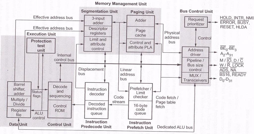
4 Block Diagram 4
5
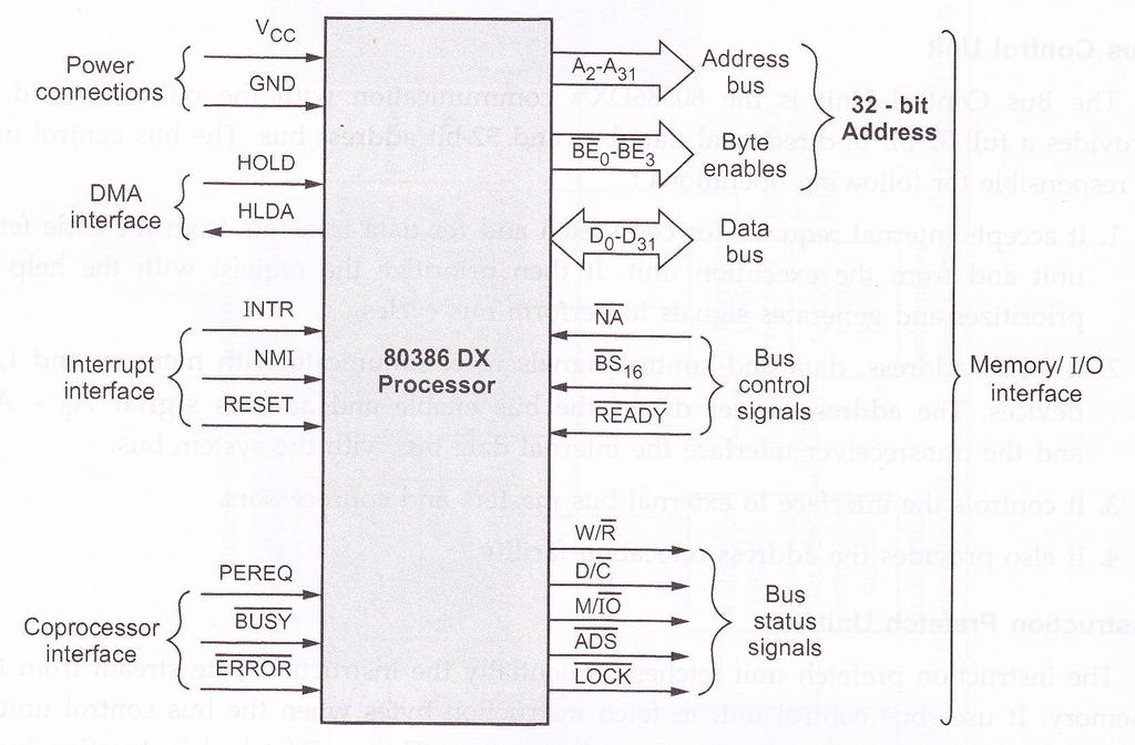
6 Pin Discription 6
7
8 Pin Discription These signals are separated in Six major groups : 1. Bus / Memory Interface Unit 2. Code Prefetch Unit 3. Instruction Decode Unit 4. Execution Unit 5. Segmentation Unit 6. Paging Unit 8
9 Pin Discription 1. Data Bus : Memory/IO lnterface The data bus consists of 32 pins (D31 D0). These lines are used to transfer 8, 16, 24, or 32-bit data at one time. 2. Address Bus : The 80386DX generates 32-bit address. The higher 30-bits of address are sent on the A31-A2. The lower 2-bits, select one of four bytes of the 32-bit data bus. These two bits are internally decoded and sent on the four byte enable pins ( BE3- BE0) 9

10 Pin Discription Bus Status Signals : The bus status signals decide the type of bus cycle to be performed. These signals are : 1. Address status 2. Write/Read 3. Memory/IO 4. Data/Control 5. LOCK 10
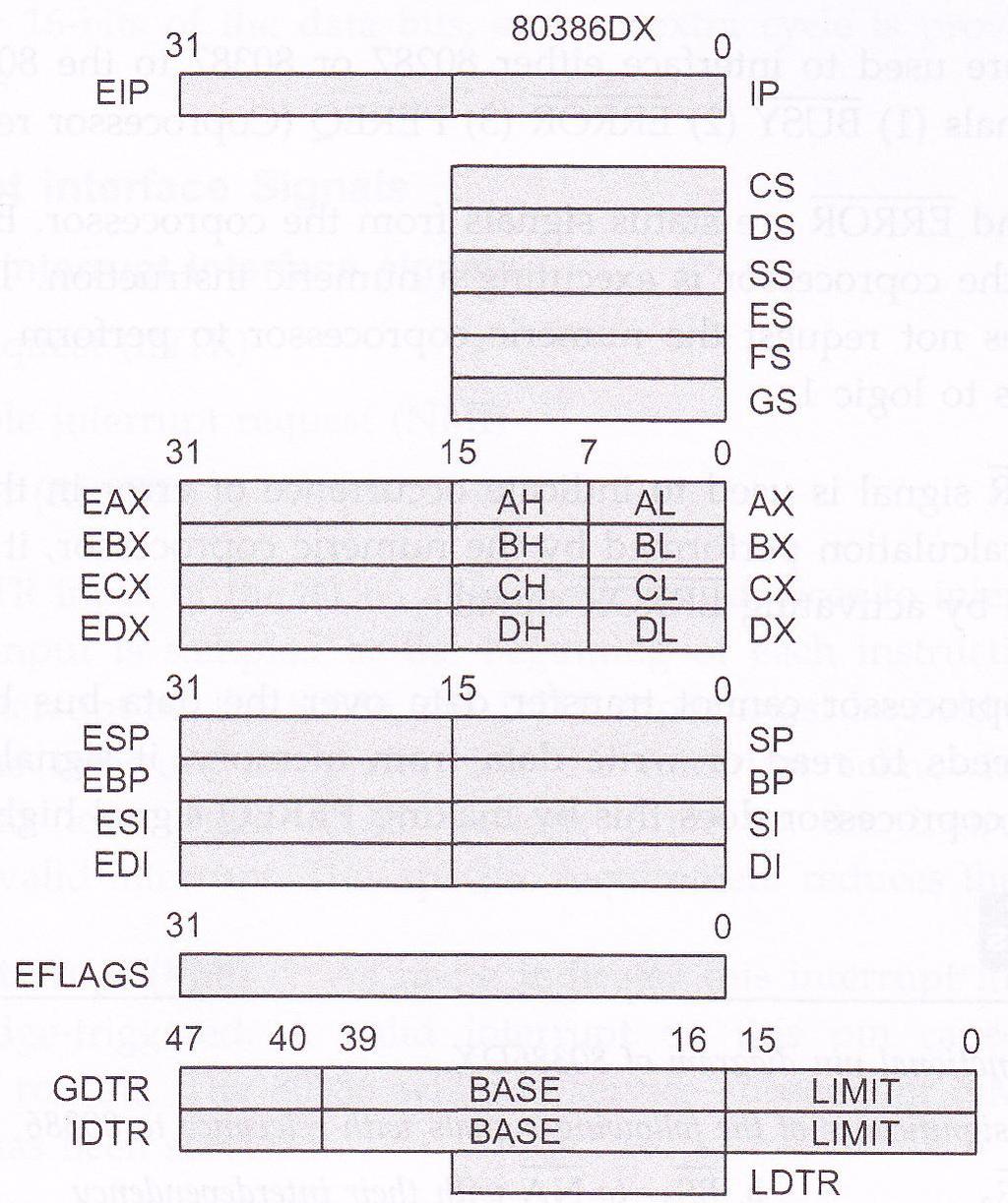
11 Register Set 11
12 12
13 General Purpose Register 13
14 14
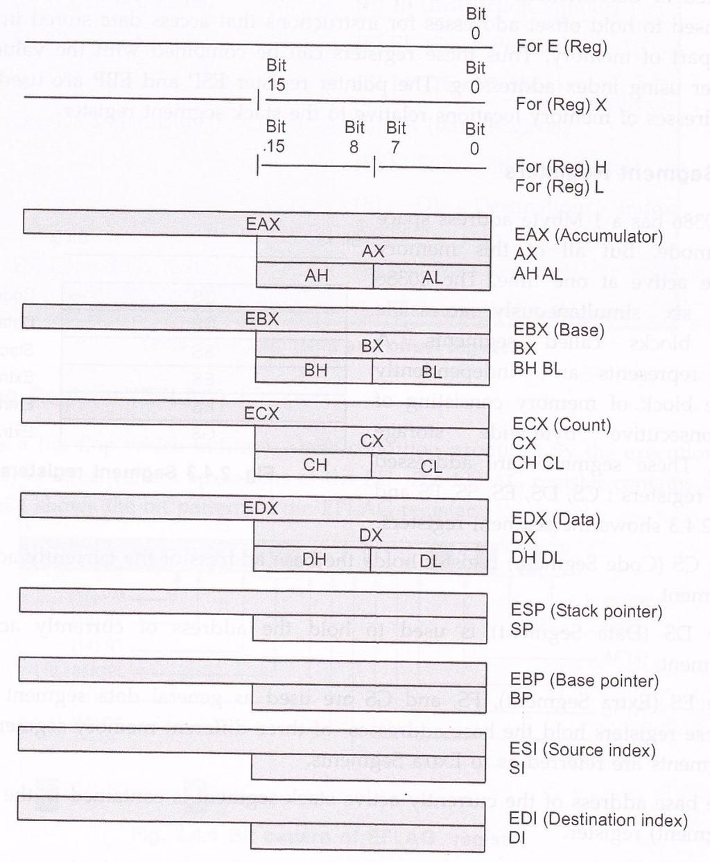
15 General Purpose Register The contains 32-bit general purpose register called EAX, EBX, ECX, EDx, ESP,EBP, ESI, and EDI. The lower 16-bits of each of the general purpose register can be accessed individually. These 16-bit registers are accessed as AX, BX, CX, DX, SP, BP, SI, and, DI respectively. The AX, BX, CX and DX registers can be further divided into fwo separate bytes : Higher byte and lower byte. 15
16 Segment Registers 16
17 17
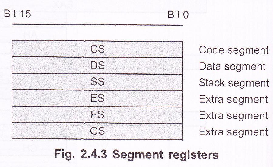
18 Segment Register The has a 1 MB address space in real mode. But all of this memory cannot be active at one time. It supports six simultaneously accessible memory blocks called segments. A segment represents an independently accessible block of memory consisting of 64 K consecutive byte-wide storage locations. These segments are addressed by 16-bit registers : CS, DS, ES, SS, FS and GS. 18
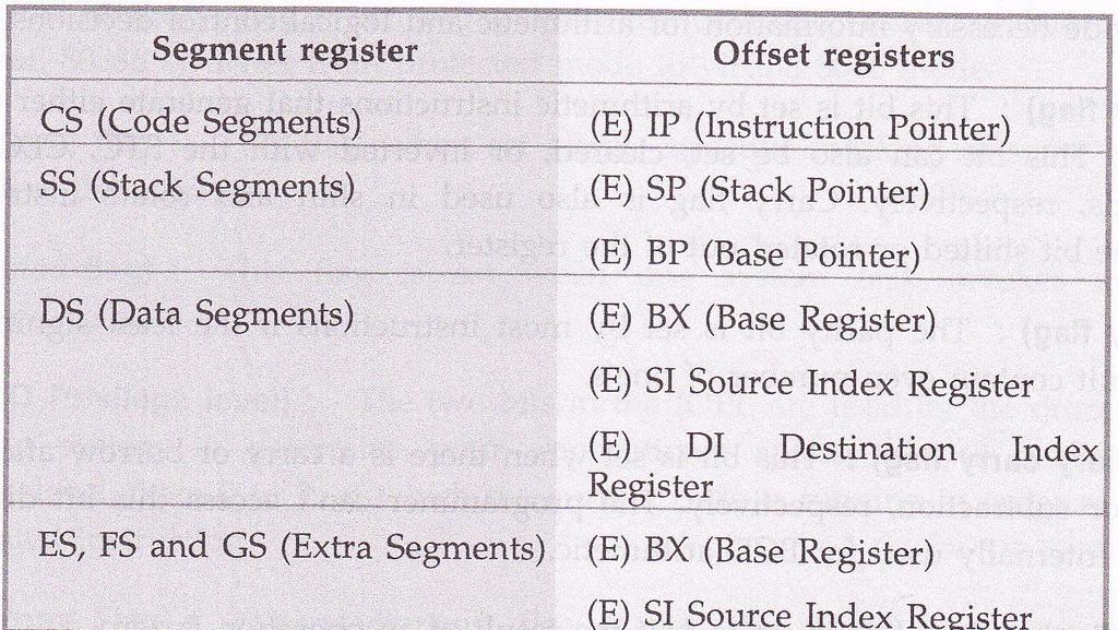
19 Segment Register 1. CS (Code Segment) : holds the base address of the currently active code segment. 2. DS (Data Segment) : is used to hold the address of currently active data segment. 3. ES (Extra Segment) FS, & GS : are used as general data segment registers. These registers hold the base addresses of three different memory segments. These segments are referred as to Extra Segments. 4. SS (Stack Segment) : The base address of the currently active. stack segment is contained in the SS register. 19
20 lndex, Pointers & Base Registers 20
21 21
22 Flag Registers 22
23 23
24 Flag Register 1. Status Flags i. CF (Carry Flag) ii. PF (Parity Flag ) iii. AF (Auxiliary Carry Flag) iv. ZF (Zero Flag) v. SF (Sign Flag) vi. OF (Overflow Flag) 2. Control Flags i. DF ( Direction flag) 3. System Flags i. VM (Virtual Memory) flag ii. R (Resume) flag iii. NT (Nested flag) iv. IOPL (l/o Privilege level) v. lf (lnterrupt Flag) vi. TF (Trap Flag) 24
25 Flag Register 1. VM (Virtual Memory) flag : Indicates operating mode of When VM flag is set, switches from protected mode to virtual 8086 mode. 2. R (Resume) flag : This flag, when set allows selective masking of some exceptions at the time of debugging. 25
26 Flag Register 1. NT (Nested flag) : This flag is set when one system task invokes another task. (i.e. nested task). 2. IOPL (l/o Privilege level) : The two bits in the IOPL are used by the processor and the operating system to determine your application's access to I/O facilities. 26
27 Flag Register 5. lf (lnterrupt Flag) : When interrupt flag is set, the recognizes and handles external hardware interrupts on its INTR pin. If the interrupt flag is cleared, ignores any inputs on this pin. The IF flag is set and cleared with the STI and CLI istructions, respectively. 6. TF (Trap Flag) : Trap flag allows user to single-step through programs. An detects that this flag is set, it executes one instruction and then automatically generates an internal exception 1. After servicing the exception, the processor executes next instruction and repeats the process. This single stepping continues until prgram code resets this flag for debugging programs single step facility is used. 27
28 System Address Registers 28
29 29
30 System Adderss Register There are four system address register : 1. TR (Task Register) 2. IDTR (Interrupt Descriptor Table Register) 3. GDTR (Global Descriptor Table i.egrster) 4. LDTR (Local Descriptor table Register). These registers hold the addresses for the four special descriptor table segments. 30
31 System Adderss Register 1. TR (Task Register) Points to the Task state segment 2. IDTR (Interrupt Descriptor Table Register) points to the Interrupt Descriptor table (IDT) 3. GDTR (Global Descriptor Table Register) points to the Global Descriptor Table (GDT) 4. LDTR (Local Descriptor Table Register) points to the Local Descriptor Table (LDT) 31
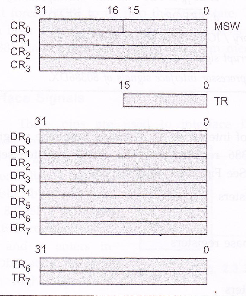
32 Control Register 32
33 33
34 Control Register There are four control registers : CR0, CR1, CR2 and CR3. These registers define the machine state that affects all the tasks in the systems. 34
35 Control Register CR0 : Holds the MSW (Machine Status Word). It contains six status bits : 1. PE (Protection Enable) 2. MP (Math Present) 3. EM (Emulate Coprocessor) 4. TS (Task Switched) 5. ET (Extension Type) 6. PG (Paging). 35
36 Control Register 1. PE (Protection Enable) : This bit is similar to the VM bit in EFLAGs in that it controls the 80386's mode of operation. When PE is set, it is in Protection mode otherwise it operates in Real Mode. 2. MP (Math Present) : When this bit is set, the assumes that real floating point hardware (80287 or 80387) is present in the system. When this bit is clear, the assumes that no such coprocessor exists, and will not attempt to use real floating point hardware. 36
37 Control Register 3. EM (Emulate coprocessor) : When this bit is set, the will generate an exception 11 (device not available) whenever it attempts to execute a floating point instruction. Programmer can use this exception handler to emulate floating point hardware in software. 4. TS (Task Switched) : The sets the bit automatically every time it performs a task switch. It will never clear this bit on its own. But programmer can clear this bit using CLTS instruction. 37
38 Control Register 5. ET (Extension Type) : When power is applied, detects whether numeric Processor connected is or & sets ET to logic 1, if numeric processor is This is necessary because the uses a slightly different protocol than PG (Paging) : This bit enables or disables paging mechanism in Memory Management Unit (MMU). If bit is set, paging is enabled. 38
39 Control Register 1. Control Register 1 (CR1) This is reserved by Intel. 2. Control Register 2 (CR2) CR2 is read-only register. The 80386, itself writes the last 32-bit linear address of page fault routine in this register. When page fault occurs, the generates exception 14 (page fault) This address is important for writing page fault routine. The page fault routine helps programmer to find cause of the fault. 39
40 Control Register 3. Control Register 3 (CR3) Control register 3 holds the physical address of the root of the two level paging tables used when paging is enabled. It is also called Page Directory Base Register 40
41 Physical Address Space 41
42 Physical Address Space The physical memory of an system is organized as a sequence of 8-bit bytes. Each byte is assigned a unique address that ranges from zero to a maximum of 2 (32) 1 (4 gigabytes) programs/ however, are independent of the physical address space. 42
43 Physical Address Space This means that programs can be written without knowledge of how much physical memory is available and without knowledge of exactly where in physical memory the instructions and data are located. The model of memory organization seen by applications programmers is determined by systems-software designers. The architecture of the gives designers the freedom to choose a model for each task. 43
44 Physical Address Space The model of memory organization can range between the following extremes: 1. Flat address space 2. Segmented address space 1. Flat address space : In a "flat" model of memory organization, the applications programmer sees a single array of up to 2 (32) bytes ( 4 gigabytes). The processor maps the 4 gigabyte flat space onto the physical address space by the address translation mechanisms. 44
45 Physical Address Space 2. Segmented address space : A segmented model consisting of a collection of up to 16,383 linear address spaces of up to 4 gigabytes each. In a segmented model of memory organization, the address space as viewed by an applications program (called the logical address space) is a much larger space of up to 2 (46) byte (64 terabytes). The processor maps the 64 terabyte logical address space onto the physical address space (up to 4 gigabytes) by the address translation mechanisms. Both models can provide memory protection. Different tasks may employ different models of memory organization. 45
46 Data Types 46
47 Data Types Data types supported by DX 47
48 Data Types 48
49 Data Types 49
50 Operating Modes 50
51 Operating Modes and above operate in either the real or protected mode. Real mode operation allows addressing of only the first 1M byte of memory space even in Pentium 4 or Core2 microprocessor. the first 1M byte of memory is called the real memory, conventional memory, or DOS memory system 51
52 Segments and Offsets All real mode memory addresses must consist of a segment address plus an offset address. segment address defines the beginning address of any 64K-byte memory segment offset address selects any location within the 64K byte memory segment Figure 2 3 shows how the segment plus offset addressing scheme selects a memory location. 52
53 FIGURE 2 3 THE REAL MODE MEMORY-ADDRESSING SCHEME, USING A SEGMENT ADDRESS PLUS AN OFFSET. this shows a memory segment beginning at 10000H, ending at location IFFFFH 64K bytes in length also shows how an offset address, called a displacement, of F000H selects location 1F000H in the memory
54 Protected Mode Memory Addressing Allows access to data and programs located within & above the first 1M byte of memory. Protected mode is where Windows operates. In place of a segment address, the segment register contains a selector that selects a descriptor from a descriptor table. The descriptor describes the memory segment s location, length, and access rights. 54
55 Selectors and Descriptors The descriptor is located in the segment register & describes the location, length, and access rights of the segment of memory. it selects one of 8192 descriptors from one of two tables of descriptors In protected mode, this segment number can address any memory location in the system for the code segment. Indirectly, the register still selects a memory segment, but not directly as in real mode. 55
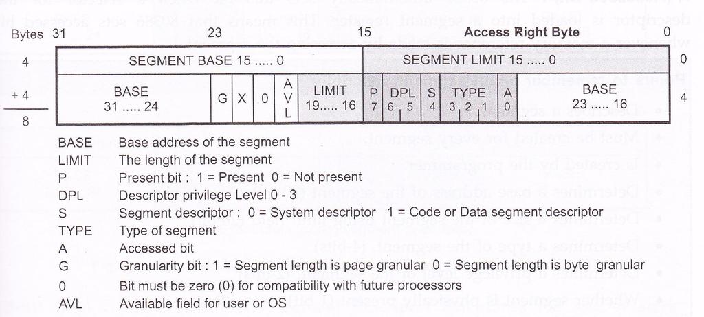
56 Selectors and Descriptors Global descriptors contain segment definitions that apply to all programs. Local descriptors are usually unique to an application. a global descriptor might be called a system descriptor, and local descriptor an application descriptor Figure shows the format of a descriptor for the through the Core2. each descriptor is 8 bytes in length global and local descriptor tables are a maximum of 64K bytes in length 56

57 The through Core2 64-bit descriptors. 57
58 Selectors and Descriptors The base address of the descriptor indicates the starting location of the memory segment. the paragraph boundary limitation is removed in protected mode segments may begin at any address The G, or granularity bit allows a segment length of 4K to 4G bytes in steps of 4K bytes. 32-bit offset address allows segment lengths of 4G bytes 16-bit offset address allows segment lengths of 64K bytes. 58
59 Protected Mode Addressing Mechanism 59
60 Protected Mode Addressing Mechanism The DX has three distinct address spaces : Logical, Linear and Physical A logical address (also known as virtual address) consists of a selector and an offset. A selector is the contents of a segment register 60


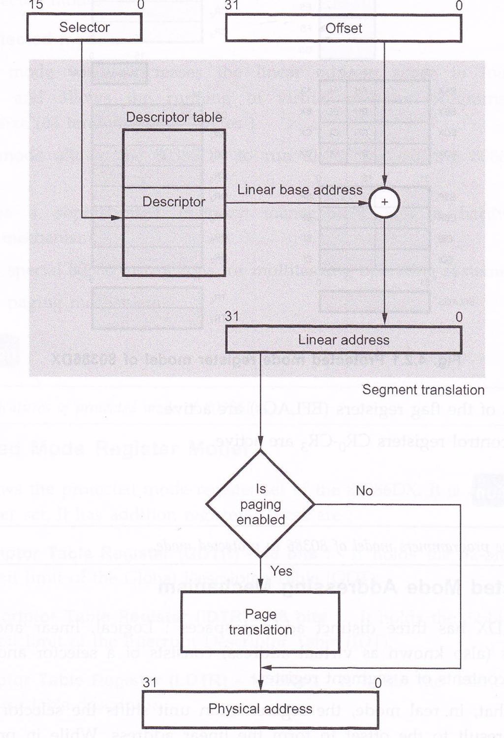
61 Protected Mode Addressing Mechanism A selector : is used to point a descriptor for the segment in a table of descriptors. In real mode : the segmentation unit shift s the selector left four bits & adds the result to the offset to form the linear address. In protected mode : Every segment selector has a linear base address associated with it, and it is stored in the segment descriptor. The linear base address from the descriptor is then added to the 32 Bit offset to generate the 32-bit linear address. This process is known as segmentation 61
62 Protected Mode Addressing Mechanism If paging unit is not enabled then the 32-bit linear address corresponds to the physical address. But if paging unit is enabled, paging mechanism translates the linear address space into the physical address space by paging translation. 62
63 63
64 Segment Descriptor 64
65 65

66 Segment Descriptor In protected mode, Memory Management Unit (MMU) uses the segment selector to access a descriptor for the desired segment in a table of descriptors in memory. Segment descriptor : is a special structure which describes the segment. Exactly one segment descriptor must be defined for each segment of the memory. 66

67 Segment Descriptor Descriptors are eight type quantities which contain attributes about a given region of linear address space (i.e. a segment). These attributes include the 32-bit base linear address of the segment, the 20-bit length and granularity of the segment, the protection level, read, write or execute privileges, the default size of the operands (15-bit or 32Bit), and the type of segment. 67
68 Segment Descriptor Base : It contains the 32-bit base address for a segment. Thus defines the location of the segment within the 4 gigabyte linear address space. The concatenates the three fragments of the base address to form a single 32-bit address. Limit : It defines the size of the segment. The concatenates the two fragments of the limit field to form a 20 bit value. The interprets this 20-bit value in two ways, depending on the setting of the granularity bit (G) : If G bit 0 : In units of 1 byte, to define a limit of up to 1 M byte (2 20 ) If G bit 1. : In units of 4 kilobytes, to define a limit of up to 4 gigabytes. 68


69 Segment Descriptor Granularity Bit : It specifies the units with which the limit field is interpreted. When bit is 0, the limit is interpreted in units of one byte; otherwise limit is interpreted in units of 4 Kbytes. 0 (Reserved by lntel) : It neither can be defined nor can be used by user. This bit must be zero for compatibility with future processors. AVL/U (User Bit) : This bit is completely undefined, and ignores it. This is available field/bit for user or operating system. 69
.")
70 Segment Descriptor Access rights byte : P (Present Bit) : If P =1 if the segment is loaded in the physical memory, If P = 0 then any attempt to access this segment causes a not present exception (exception 11). DPL (Descriptor Privilege Level) : It is a 2-bit field defines the level of privilege associated with the memory space that the descriptor defines DPL 0 is the most privileged whereas DPL 3 is the least privilege Type : This specifies the specific descriptors among various kinds of descriptors. 70
71 Segment Descriptor S (System Bit) : The segment S bit in the segment descriptor determines if a given segment is a system segment or a code or a data segment. If the S bit is 1 then the segment is either a code or data segment, if it is 0 then the segment is system segment. A (Accessed Bit) : The automatically sets this bit when a selector for the descriptor is loaded into a segment register. This means that sets accessed bit whenever a memory reference is made by accessing the segment. 71
72 Types Segment Descriptor 72
73 Types Segment Descriptor 73
74 Types Segment Descriptor: Non-System Segment Descriptors Non-System Segment Descriptors Data Segment Descriptor 74
75 Types Segment Descriptor: Non-System Segment Descriptors Code Segment Descriptor 75

76 Types Segment Descriptor: System Segment Descriptors Systeme Segment Descriptor 76

77 Types Segment Descriptor: System Segment Descriptors 77

78 Types Segment Descriptor: System Segment Descriptors 78
79 Types Segment Descriptor: System Segment Descriptors 79


80 Types Segment Descriptor: System Segment Descriptors Gate Descriptor 80
81 Descriptor Table 81
82 Descriptor Table Segment descriptors are grouped and placed one after the other in contiguous memory locations. This group arrangement is known as a descriptor table. The maximum limit for the length of descriptor table is 64 kbytes and each descriptor takes 8 bytes to store the information of a particular segment. So descriptor table can have as many as 8192 descriptors. The upper 13 bits of a selector are used as an index into the descriptor table. 82
83 Descriptor Table There are three types of descriptor tables : Global Descriptor Table (GDT) : It is a general purpose table of descriptors, can be used by all programs to reference segments of memory. The GDT can have any type of segment descriptor except for descriptors which are used for serving interrupts. Interrupt Descriptor Table (IDT) : It holds the segment descriptors that define interrupt or exception handling routines. The IDT is a direct replacement for the interrupt vector table used in 8085 system. Local Descriptor Tables (LDT) : They are set up in the system for individual task or closely related group of tasks. 83
84 Descriptor Table 84
85 GDTR 85
86 Descriptor Table : GDTR 86
87 Descriptor Table : GDTR GDTR is a 48-bit register located inside the 80386DX. The lower two bytes of this register specifies the LIMIT (in bytes) for the GDT. The value of limit is 1 less than the actual size of the table. For example, if LIMIT is 03FFH then the table is 1024( ) bytes in length (03FFH =102316). Since the LIMIT field is 16 bit long, the GDT can grow up to 65,536 bytes long. The upper four bytgs of GDTR specifies the 32-bit linear address of the base of the Global Descriptor Table (GDT). 87
88 IDTR 88
89 Descriptor Table : IDTR 89
90 Descriptor Table : IDTR Like global descriptor table register, Interrupt descriptor table register (IDTR) holds the 16-bit limit and 32-bit linear address of the base of the Interrupt Descriptor Table (IDT). Interrupt Descriptor Table Register are used to define a Interrupt Descriptor Table (IDT) in the 80386DX physical memory address space. Like GDTR the IDTR is also 48 bit in length, with lower two bytes defines Limits and upper 4 bytes defines the base address. Since limit field is two bytes, the IDT can also be up to 65,536 bytes long. But the 803B6DX only supports upto 256 interrupts or exceptions; therefore, the size of the IDT should not be set to support more than 256 interrupts. 90
91 LDTR 91

92 Descriptor Table : LDTR 92
93 Descriptor Table : LDTR Unlike GDTR and IDTR, the LDTR is a 16-bit register. It does not specify any limit or base address for the segment but it specifies the address of the LDT descriptor stored in the Global Descriptor Table (GDT) LDTR holds a selector that points to an LDT descriptor in the GDT. Whenever a selector is loaded into the LDTR, the corresponding descriptor is located in the global descriptor table. The contents of this descriptor defines the local descriptor table. The 32-bit base value defines starting point of the table in the 80386DX physical memory address space and 16-bit limit specifies the size of the table. 93
94 Descriptor Table : LDTR The GDT can contain many LDT descriptors. To put particular LDT in service, it is necessary to load the LDTR with corresponding selector. For loading the values in GDTR, IDTR and LDTR registers, 80336DX provides LGDT, LLDT, and LIDT instructions. It also provides SGDT, SLDT and SIDT instructions. These (48 bits) instructions copy the contents of the descriptor table registers into the six bytes of memory pointed by the destination operand. These tables are manipulated by the operating system. Thus, the instructions used for loading the descriptor tables are privileged instructions. 94
95 Segmentation 95
96 96
97 Segmentation Segmentation is a process of converting logical address into a linear address. The 13-bit index part of selector is multiplied by 8 and used as a pointer to the desired descriptor in a descriptor table. The index value is multiplied by 8 because each descriptor requires 8 bytes in the descriptor table. The descriptor in the descriptor table contains mainly base address, segment limit and access right byte. The adds the base address from the descriptor to the effective address or offset to generate a linear address. 97
98 Segmentation The selector component of each logical address contains 2 bits which represent the privilege level of the program section requesting access to a segment. Level 0 is the most privileged and level 3 is the least privileged. More previleged levels are numerically smaller than less privileged levels. The descriptor of each segment contains 2 bits which represent the privilege level of that segment. When an executing program attempts to access a segment, the memory management unit compares the privilege level in the selector with the privilege level in the descriptor 98
99 Segmentation If the segment selector has the same or greater privilege level, then the memory management unit allows the segment to be accessed. If the selector privilege level is lower than the privilege level of the segment, the memory management unit denies the access and sends an interrupt signal to the CPU indicating a privilege level violation. 99
100 Segmentation There are two major categories of descriptor table in a system : Global Descriptor Table (GDT) is a general purpose table of descriptors, can be used by all programs to reference segments of memory. Local Descriptor Table (LDT) are set up in the system for individual task or closely related group of tasks. The Table Indicator (TI) bit in the selector decides which descriptor table should be referred by the selector. When TI bit is 0, the index portion of the selector refers to a descriptor in the GDT. When TI bit is 1, it refers to descriptor in the current LDT. 100
101 101
MICROPROCESSOR MICROPROCESSOR ARCHITECTURE. Prof. P. C. Patil UOP S.E.COMP (SEM-II)
") MICROPROCESSOR UOP S.E.COMP (SEM-II) 80386 MICROPROCESSOR ARCHITECTURE Prof. P. C. Patil Department of Computer Engg Sandip Institute of Engineering & Management Nashik pc.patil@siem.org.in 1 Introduction
MICROPROCESSOR UOP S.E.COMP (SEM-II) 80386 MICROPROCESSOR ARCHITECTURE Prof. P. C. Patil Department of Computer Engg Sandip Institute of Engineering & Management Nashik pc.patil@siem.org.in 1 Introduction
MICROPROCESSOR ALL IN ONE. Prof. P. C. Patil UOP S.E.COMP (SEM-II)
") MICROPROCESSOR UOP S.E.COMP (SEM-II) 80386 ALL IN ONE Prof. P. C. Patil Department of Computer Engg Sandip Institute of Engineering & Management Nashik pc.patil@siem.org.in 1 Architecture of 80386 2 ARCHITECTURE
MICROPROCESSOR UOP S.E.COMP (SEM-II) 80386 ALL IN ONE Prof. P. C. Patil Department of Computer Engg Sandip Institute of Engineering & Management Nashik pc.patil@siem.org.in 1 Architecture of 80386 2 ARCHITECTURE
IA32 Intel 32-bit Architecture
 1 2 IA32 Intel 32-bit Architecture Intel 32-bit Architecture (IA32) 32-bit machine CISC: 32-bit internal and external data bus 32-bit external address bus 8086 general registers extended to 32 bit width
Chapter 2: The Microprocessor and its Architecture
 Chapter 2: The Microprocessor and its Architecture Chapter 2: The Microprocessor and its Architecture Chapter 2: The Microprocessor and its Architecture Introduction This chapter presents the microprocessor
6/17/2011. Introduction. Chapter Objectives Upon completion of this chapter, you will be able to:
 Chapter 2: The Microprocessor and its Architecture Chapter 2: The Microprocessor and its Architecture Chapter 2: The Microprocessor and its Architecture Introduction This chapter presents the microprocessor
Unit 08 Advanced Microprocessor
 Unit 08 Advanced Microprocessor 1. Features of 80386 The 80386 microprocessor is an enhanced version of the 80286 microprocessor Memory-management unit is enhanced to provide memory paging. The 80386 also
Darshan Institute of Engineering & Technology
 1. Explain 80286 architecture. OR List the four major processing units in an 80286 microprocessor and briefly describe the function of each. Ans - The 80286 was designed for multi-user systems with multitasking
Basic Execution Environment
 Basic Execution Environment 3 CHAPTER 3 BASIC EXECUTION ENVIRONMENT This chapter describes the basic execution environment of an Intel Architecture processor as seen by assembly-language programmers.
iapx Systems Electronic Computers M
 iapx Systems Electronic Computers M 1 iapx History We analyze 32 bit systems: generalization to 64 bits is straigtforward Segment Registers (16 bits) Code Segment Stack Segment Data Segment Extra Ssegment
EXPERIMENT WRITE UP. LEARNING OBJECTIVES: 1. Get hands on experience with Assembly Language Programming 2. Write and debug programs in TASM/MASM
 EXPERIMENT WRITE UP AIM: Assembly language program for 16 bit BCD addition LEARNING OBJECTIVES: 1. Get hands on experience with Assembly Language Programming 2. Write and debug programs in TASM/MASM TOOLS/SOFTWARE
The Microprocessor and its Architecture
 The Microprocessor and its Architecture Contents Internal architecture of the Microprocessor: The programmer s model, i.e. The registers model The processor model (organization) Real mode memory addressing
Lecture (02) The Microprocessor and Its Architecture By: Dr. Ahmed ElShafee
 The Microprocessor and Its Architecture By: Dr. Ahmed ElShafee") Lecture (02) The Microprocessor and Its Architecture By: Dr. Ahmed ElShafee ١ INTERNAL MICROPROCESSOR ARCHITECTURE Before a program is written or instruction investigated, internal configuration of the
Lecture (02) The Microprocessor and Its Architecture By: Dr. Ahmed ElShafee ١ INTERNAL MICROPROCESSOR ARCHITECTURE Before a program is written or instruction investigated, internal configuration of the
Architecture of 8086 Microprocessor
 MCQ on Microprocessor and Interfacing Technique S.E.Compure (Sem-II) UNIT 1 Architecture of 8086 Microprocessor 1 marks Questions 1. Which is first microprocessor? (a) 8008 (b) 8085 (c) 8086 (d) 4004 2.
Introduction to IA-32. Jo, Heeseung
 Introduction to IA-32 Jo, Heeseung IA-32 Processors Evolutionary design Starting in 1978 with 8086 Added more features as time goes on Still support old features, although obsolete Totally dominate computer
INTRODUCTION TO IA-32. Jo, Heeseung
 INTRODUCTION TO IA-32 Jo, Heeseung IA-32 PROCESSORS Evolutionary design Starting in 1978 with 8086 Added more features as time goes on Still support old features, although obsolete Totally dominate computer
EEM336 Microprocessors I. The Microprocessor and Its Architecture
 EEM336 Microprocessors I The Microprocessor and Its Architecture Introduction This chapter presents the microprocessor as a programmable device by first looking at its internal programming model and then
1. state the priority of interrupts of Draw and explain MSW format of List salient features of
 Q.1) 1. state the priority of interrupts of 80286. Ans- 1. Instruction exceptions 2. Single step 3. NMI 4. Processor extension segment overrun 5. INTR 6. INT 2. Draw and explain MSW format of 80286. Ans-
Hardware and Software Architecture. Chapter 2
 Hardware and Software Architecture Chapter 2 1 Basic Components The x86 processor communicates with main memory and I/O devices via buses Data bus for transferring data Address bus for the address of a
BASIC INTERRUPT PROCESSING
 Interrupts BASIC INTERRUPT PROCESSING This section discusses the function of an interrupt in a microprocessor-based system. Structure and features of interrupts available to Intel microprocessors. The
Complex Instruction Set Computer (CISC)
") Introduction ti to IA-32 IA-32 Processors Evolutionary design Starting in 1978 with 886 Added more features as time goes on Still support old features, although obsolete Totally dominate computer market
Introduction ti to IA-32 IA-32 Processors Evolutionary design Starting in 1978 with 886 Added more features as time goes on Still support old features, although obsolete Totally dominate computer market
2.5 Address Space. The IBM 6x86 CPU can directly address 64 KBytes of I/O space and 4 GBytes of physical memory (Figure 2-24).
.") Address Space 2.5 Address Space The IBM 6x86 CPU can directly address 64 KBytes of I/O space and 4 GBytes of physical memory (Figure 2-24). Memory Address Space. Access can be made to memory addresses
Address Space 2.5 Address Space The IBM 6x86 CPU can directly address 64 KBytes of I/O space and 4 GBytes of physical memory (Figure 2-24). Memory Address Space. Access can be made to memory addresses
Assembler Programming. Lecture 2
 Assembler Programming Lecture 2 Lecture 2 8086 family architecture. From 8086 to Pentium4. Registers, flags, memory organization. Logical, physical, effective address. Addressing modes. Processor Processor
Intel 8086 MICROPROCESSOR ARCHITECTURE
 Intel 8086 MICROPROCESSOR ARCHITECTURE 1 Features It is a 16-bit μp. 8086 has a 20 bit address bus can access up to 2 20 memory locations (1 MB). It can support up to 64K I/O ports. It provides 14, 16
We can study computer architectures by starting with the basic building blocks. Adders, decoders, multiplexors, flip-flops, registers,...
 COMPUTER ARCHITECTURE II: MICROPROCESSOR PROGRAMMING We can study computer architectures by starting with the basic building blocks Transistors and logic gates To build more complex circuits Adders, decoders,
PROTECTION CHAPTER 4 PROTECTION
 Protection 4 CHAPTER 4 PROTECTION In protected mode, the Intel Architecture provides a protection mechanism that operates at both the segment level and the page level. This protection mechanism provides
Internal architecture of 8086
 Case Study: Intel Processors Internal architecture of 8086 Slide 1 Case Study: Intel Processors FEATURES OF 8086 It is a 16-bit μp. 8086 has a 20 bit address bus can access up to 220 memory locations (1
UNIT 2 PROCESSORS ORGANIZATION CONT.
 UNIT 2 PROCESSORS ORGANIZATION CONT. Types of Operand Addresses Numbers Integer/floating point Characters ASCII etc. Logical Data Bits or flags x86 Data Types Operands in 8 bit -Byte 16 bit- word 32 bit-
icroprocessor istory of Microprocessor ntel 8086:
 Microprocessor A microprocessor is an electronic device which computes on the given input similar to CPU of a computer. It is made by fabricating millions (or billions) of transistors on a single chip.
Microprocessors and Microcontrollers/High end processors
 Module 8 learning unit 18 Architecture of 8386 The Internal Architecture of 8386 is divided into 3 sections. Central processing unit Memory management unit Bus interface unit Central processing unit is
Moodle WILLINGDON COLLEGE SANGLI (B. SC.-II) Digital Electronics
 Digital Electronics") Moodle 4 WILLINGDON COLLEGE SANGLI (B. SC.-II) Digital Electronics Advanced Microprocessors and Introduction to Microcontroller Moodle developed By Dr. S. R. Kumbhar Department of Electronics Willingdon
Moodle 4 WILLINGDON COLLEGE SANGLI (B. SC.-II) Digital Electronics Advanced Microprocessors and Introduction to Microcontroller Moodle developed By Dr. S. R. Kumbhar Department of Electronics Willingdon
Intel 8086 MICROPROCESSOR. By Y V S Murthy
 Intel 8086 MICROPROCESSOR By Y V S Murthy 1 Features It is a 16-bit μp. 8086 has a 20 bit address bus can access up to 2 20 memory locations (1 MB). It can support up to 64K I/O ports. It provides 14,
MILITARY Intel386 TM HIGH PERFORMANCE 32-BIT MICROPROCESSOR WITH INTEGRATED MEMORY MANAGEMENT
 MILITARY Intel386 TM HIGH PERFORMANCE 32-BIT MICROPROCESSOR WITH INTEGRATED MEMORY MANAGEMENT Y Y Y Y Flexible 32-Bit Microprocessor 8 16 32-Bit Data Types 8 General Purpose 32-Bit Registers Very Large
8086 INTERNAL ARCHITECTURE
 8086 INTERNAL ARCHITECTURE Segment 2 Intel 8086 Microprocessor The 8086 CPU is divided into two independent functional parts: a) The Bus interface unit (BIU) b) Execution Unit (EU) Dividing the work between
Code segment Stack segment
 Registers Most of the registers contain data/instruction offsets within 64 KB memory segment. There are four different 64 KB segments for instructions, stack, data and extra data. To specify where in 1
EC-333 Microprocessor and Interfacing Techniques
 EC-333 Microprocessor and Interfacing Techniques Lecture 3 The Microprocessor and its Architecture Dr Hashim Ali Fall - 2018 Department of Computer Science and Engineering HITEC University Taxila Slides
Addressing Modes on the x86
 Addressing Modes on the x86 register addressing mode mov ax, ax, mov ax, bx mov ax, cx mov ax, dx constant addressing mode mov ax, 25 mov bx, 195 mov cx, 2056 mov dx, 1000 accessing data in memory There
Introduction to The x86 Microprocessor
 Introduction to The x86 Microprocessor Prof. V. Kamakoti Digital Circuits And VLSI Laboratory Indian Institute of Technology, Madras Chennai - 600 036. http://vlsi.cs.iitm.ernet.in Protected Mode Memory
Microkernel Construction
 Kernel Entry / Exit SS2013 Control Transfer Microkernel User Stack A Address Space Kernel Stack A User Stack User Stack B Address Space Kernel Stack B User Stack 1. Kernel Entry (A) 2. Thread Switch (A
iapx86 Protection Electronic Computers M
 iapx86 Protection Electronic Computers M 1 Protection Multitasking (multiple processes) > the system must prevent an uncontrolled access of a process to the memory space of another process....and that
MICROPROCESSOR TECHNOLOGY
 MICROPROCESSOR TECHNOLOGY Assis. Prof. Hossam El-Din Moustafa Lecture 15 Ch.7 The 80386 and 80486 Microprocessors 21-Apr-15 1 Chapter Objectives Contrast the 80386 and 80486 microprocessors with earlier
Computer Organization (II) IA-32 Processor Architecture. Pu-Jen Cheng
 IA-32 Processor Architecture. Pu-Jen Cheng") Computer Organization & Assembly Languages Computer Organization (II) IA-32 Processor Architecture Pu-Jen Cheng Materials Some materials used in this course are adapted from The slides prepared by Kip
Computer Organization & Assembly Languages Computer Organization (II) IA-32 Processor Architecture Pu-Jen Cheng Materials Some materials used in this course are adapted from The slides prepared by Kip
SRI VENKATESWARA COLLEGE OF ENGINEERING AND TECHNOLOGY DEPARTMENT OF ECE EC6504 MICROPROCESSOR AND MICROCONTROLLER (REGULATION 2013)
") SRI VENKATESWARA COLLEGE OF ENGINEERING AND TECHNOLOGY DEPARTMENT OF ECE EC6504 MICROPROCESSOR AND MICROCONTROLLER (REGULATION 2013) UNIT I THE 8086 MICROPROCESSOR PART A (2 MARKS) 1. What are the functional
SRI VENKATESWARA COLLEGE OF ENGINEERING AND TECHNOLOGY DEPARTMENT OF ECE EC6504 MICROPROCESSOR AND MICROCONTROLLER (REGULATION 2013) UNIT I THE 8086 MICROPROCESSOR PART A (2 MARKS) 1. What are the functional
Summer 2003 Lecture 27 07/28/03
 Summer 2003 Lecture 27 07/28/03 Protected Mode Operation of Intel x86 Processors Protected Virtual Address Mode, commonly called Protected Mode, is an advanced mode of operation of 80x86 processors beginning
Introduction to Microprocessor
 Introduction to Microprocessor The microprocessor is a general purpose programmable logic device. It is the brain of the computer and it performs all the computational tasks, calculations data processing
Low Level Programming Lecture 2. International Faculty of Engineerig, Technical University of Łódź
 Low Level Programming Lecture 2 Intel processors' architecture reminder Fig. 1. IA32 Registers IA general purpose registers EAX- accumulator, usually used to store results of integer arithmetical or binary
The Pentium Processor
 The Pentium Processor Chapter 7 S. Dandamudi Outline Pentium family history Pentium processor details Pentium registers Data Pointer and index Control Segment Real mode memory architecture Protected mode
MICROPROCESSOR ARCHITECTURE
 MICROPROCESSOR ARCHITECTURE UOP S.E.COMP (SEM-I) OPERATING IN REAL MODE Prof.P.C.Patil Department of Computer Engg Matoshri College of Engg.Nasik pcpatil18@gmail.com. Introduction 2 Introduction The 80386
Lecture 15 Intel Manual, Vol. 1, Chapter 3. Fri, Mar 6, Hampden-Sydney College. The x86 Architecture. Robb T. Koether. Overview of the x86
 Lecture 15 Intel Manual, Vol. 1, Chapter 3 Hampden-Sydney College Fri, Mar 6, 2009 Outline 1 2 Overview See the reference IA-32 Intel Software Developer s Manual Volume 1: Basic, Chapter 3. Instructions
UMBC. contain new IP while 4th and 5th bytes contain CS. CALL BX and CALL [BX] versions also exist. contain displacement added to IP.
![UMBC. contain new IP while 4th and 5th bytes contain CS. CALL BX and CALL [BX] versions also exist. contain displacement added to IP.](/thumbs/74/70839578.jpg "UMBC. contain new IP while 4th and 5th bytes contain CS. CALL BX and CALL [BX] versions also exist. contain displacement added to IP.") Procedures: CALL: Pushes the address of the instruction following the CALL instruction onto the stack. RET: Pops the address. SUM PROC NEAR USES BX CX DX ADD AX, BX ADD AX, CX MOV AX, DX RET SUM ENDP NEAR
Procedures: CALL: Pushes the address of the instruction following the CALL instruction onto the stack. RET: Pops the address. SUM PROC NEAR USES BX CX DX ADD AX, BX ADD AX, CX MOV AX, DX RET SUM ENDP NEAR
MICROPROCESSOR PROGRAMMING AND SYSTEM DESIGN
 MICROPROCESSOR PROGRAMMING AND SYSTEM DESIGN ROAD MAP SDK-86 Intel 8086 Features 8086 Block Diagram 8086 Architecture Bus Interface Unit Execution Unit 8086 Architecture 8086 Programmer s Model Flag Register
SYSC3601 Microprocessor Systems. Unit 2: The Intel 8086 Architecture and Programming Model
 SYSC3601 Microprocessor Systems Unit 2: The Intel 8086 Architecture and Programming Model Topics/Reading SYSC3601 2 Microprocessor Systems 1. Registers and internal architecture (Ch 2) 2. Address generation
Chapter 12: INTERRUPTS
 Chapter 12: INTERRUPTS 12 1 BASIC INTERRUPT PROCESSING This section discusses the function of an interrupt in a microprocessor-based system. Structure and features of interrupts available to Intel microprocessors.
IA-32 Architecture COE 205. Computer Organization and Assembly Language. Computer Engineering Department
 IA-32 Architecture COE 205 Computer Organization and Assembly Language Computer Engineering Department King Fahd University of Petroleum and Minerals Presentation Outline Basic Computer Organization Intel
MICROPROCESSOR TECHNOLOGY
 MICROPROCESSOR TECHNOLOGY Assis. Prof. Hossam El-Din Moustafa Lecture 16 Ch.7 The 80386 and 80486 Microprocessors 21-Apr-15 1 System Descriptors The system descriptor defines information about the system
Lecture 5:8086 Outline: 1. introduction 2. execution unit 3. bus interface unit
 Lecture 5:8086 Outline: 1. introduction 2. execution unit 3. bus interface unit 1 1. introduction The internal function of 8086 processor are partitioned logically into processing units,bus Interface Unit(BIU)
Microkernel Construction
 Microkernel Construction Kernel Entry / Exit Nils Asmussen 05/04/2017 1 / 45 Outline x86 Details Protection Facilities Interrupts and Exceptions Instructions for Entry/Exit Entering NOVA Leaving NOVA 2
Tutorial 10 Protection Cont.
 Tutorial 0 Protection Cont. 2 Privilege Levels Lower number => higher privilege Code can access data of equal/lower privilege levels only Code can call more privileged data via call gates Each level has
3.6. PAGING (VIRTUAL MEMORY) OVERVIEW
 OVERVIEW") an eight-byte boundary to yield the best processor performance. The limit value for the GDT is expressed in bytes. As with segments, the limit value is added to the base address to get the address of the
an eight-byte boundary to yield the best processor performance. The limit value for the GDT is expressed in bytes. As with segments, the limit value is added to the base address to get the address of the
Chapter 2 COMPUTER SYSTEM HARDWARE
 Chapter 2 COMPUTER SYSTEM HARDWARE A digital computer system consists of hardware and software. The hardware consists of the physical components of the system, whereas the software is the collection of
The Purpose of Interrupt
 Interrupts 3 Introduction In this chapter, the coverage of basic I/O and programmable peripheral interfaces is expanded by examining a technique called interrupt-processed I/O. An interrupt is a hardware-initiated
16-Bit Intel Processor Architecture
 IBM-PC Organization 16-Bit Intel Processor Architecture A-16 bit microprocessor can operate on 16 bits of data at a time. 8086/8088 have the simplest structure 8086/8088 have the same instruction set,
The x86 Architecture
 The x86 Architecture Lecture 24 Intel Manual, Vol. 1, Chapter 3 Robb T. Koether Hampden-Sydney College Fri, Mar 20, 2015 Robb T. Koether (Hampden-Sydney College) The x86 Architecture Fri, Mar 20, 2015
Processor Structure and Function
 WEEK 4 + Chapter 14 Processor Structure and Function + Processor Organization Processor Requirements: Fetch instruction The processor reads an instruction from memory (register, cache, main memory) Interpret
CHAPTER 3 BASIC EXECUTION ENVIRONMENT
 CHAPTER 3 BASIC EXECUTION ENVIRONMENT This chapter describes the basic execution environment of an Intel 64 or I A-32 processor as seen by assemblylanguage programmers. It describes how the processor executes
MICROPROCESSOR TECHNOLOGY
 MICROPROCESSOR TECHNOLOGY Assis. Prof. Hossam El-Din Moustafa Lecture 5 Ch.2 A Top-Level View of Computer Function (Cont.) 24-Feb-15 1 CPU (CISC & RISC) Intel CISC, Motorola RISC CISC (Complex Instruction
A Presentation created By Ramesh.K Press Ctrl+l for full screen view
 Press Ctrl+l for full screen view A Presentation created By Ramesh.K rameshpkd@gmail.com Press Ctrl+l for full screen view A Microprocessor sor is a multipurpose, programmable logic device that reads binary
Dr. Ramesh K. Karne Department of Computer and Information Sciences, Towson University, Towson, MD /12/2014 Slide 1
 Dr. Ramesh K. Karne Department of Computer and Information Sciences, Towson University, Towson, MD 21252 rkarne@towson.edu 11/12/2014 Slide 1 Intel x86 Aseembly Language Assembly Language Assembly Language
ADVANCED PROCESSOR ARCHITECTURES AND MEMORY ORGANISATION Lesson-11: 80x86 Architecture
 ADVANCED PROCESSOR ARCHITECTURES AND MEMORY ORGANISATION Lesson-11: 80x86 Architecture 1 The 80x86 architecture processors popular since its application in IBM PC (personal computer). 2 First Four generations
IA32/Linux Virtual Memory Architecture
 IA32/Linux Virtual Memory Architecture Basic Execution Environment Application Programming Registers General-purpose registers 31 0 EAX AH AL EBX BH BL ECX CH CL EDX DH DL EBP ESI EDI BP SI DI Segment
AMD-K5. Software Development Guide PROCESSOR
 AMD-K5 TM PROCESSOR Software Development Guide Publication # 20007 Rev: D Amendment/0 Issue Date: September 1996 This document contains information on a product under development at Advanced Micro Devices
Information Security II Prof. Kamakoti Department of Computer Science and Engineering Indian Institute of Technology, Madras
 Information Security II Prof. Kamakoti Department of Computer Science and Engineering Indian Institute of Technology, Madras Lecture 30 Task Switch recap - Week 6 (Refer Slide Time: 00:09) So welcome back
Marking Scheme. Examination Paper Department of CE. Module: Microprocessors (630313)
") Philadelphia University Faculty of Engineering Marking Scheme Examination Paper Department of CE Module: Microprocessors (630313) Final Exam Second Semester Date: 02/06/2018 Section 1 Weighting 40% of
Philadelphia University Faculty of Engineering Marking Scheme Examination Paper Department of CE Module: Microprocessors (630313) Final Exam Second Semester Date: 02/06/2018 Section 1 Weighting 40% of
William Stallings Computer Organization and Architecture 10 th Edition Pearson Education, Inc., Hoboken, NJ. All rights reserved.
 + William Stallings Computer Organization and Architecture 10 th Edition 2016 Pearson Education, Inc., Hoboken, NJ. All rights reserved. 2 + Chapter 14 Processor Structure and Function + Processor Organization
The Instruction Set. Chapter 5
 The Instruction Set Architecture Level(ISA) Chapter 5 1 ISA Level The ISA level l is the interface between the compilers and the hardware. (ISA level code is what a compiler outputs) 2 Memory Models An
M80C286 HIGH PERFORMANCE CHMOS MICROPROCESSOR WITH MEMORY MANAGEMENT AND PROTECTION
 HIGH PERFORMANCE CHMOS MICROPROCESSOR WITH MEMORY MANAGEMENT AND PROTECTION Military Y High Speed CHMOS III Technology Pin for Pin Clock for Clock and Functionally Compatible with the HMOS M80286 Y 10
Scott M. Lewandowski CS295-2: Advanced Topics in Debugging September 21, 1998
 Scott M. Lewandowski CS295-2: Advanced Topics in Debugging September 21, 1998 Assembler Syntax Everything looks like this: label: instruction dest,src instruction label Comments: comment $ This is a comment
Assembly Language. Lecture 2 - x86 Processor Architecture. Ahmed Sallam
 Assembly Language Lecture 2 - x86 Processor Architecture Ahmed Sallam Introduction to the course Outcomes of Lecture 1 Always check the course website Don t forget the deadline rule!! Motivations for studying
SPRING TERM BM 310E MICROPROCESSORS LABORATORY PRELIMINARY STUDY
 BACKGROUND 8086 CPU has 8 general purpose registers listed below: AX - the accumulator register (divided into AH / AL): 1. Generates shortest machine code 2. Arithmetic, logic and data transfer 3. One
CC411: Introduction To Microprocessors
 CC411: Introduction To Microprocessors OBJECTIVES this chapter enables the student to: Describe the Intel family of microprocessors from 8085 to Pentium. In terms of bus size, physical memory & special
9/25/ Software & Hardware Architecture
 8086 Software & Hardware Architecture 1 INTRODUCTION It is a multipurpose programmable clock drive register based integrated electronic device, that reads binary instructions from a storage device called
Machine-level Representation of Programs. Jin-Soo Kim Computer Systems Laboratory Sungkyunkwan University
 Machine-level Representation of Programs Jin-Soo Kim (jinsookim@skku.edu) Computer Systems Laboratory Sungkyunkwan University http://csl.skku.edu Program? 짬뽕라면 준비시간 :10 분, 조리시간 :10 분 재료라면 1개, 스프 1봉지, 오징어
Mechanisms for entering the system
 Mechanisms for entering the system Yolanda Becerra Fontal Juan José Costa Prats Facultat d'informàtica de Barcelona (FIB) Universitat Politècnica de Catalunya (UPC) BarcelonaTech 2017-2018 QP Content Introduction
7/19/2013. Introduction. Chapter Objectives Upon completion of this chapter, you will be able to: Chapter Objectives 12 1 BASIC INTERRUPT PROCESSING
 Chapter 12: Interrupts Introduction In this chapter, the coverage of basic I/O and programmable peripheral interfaces is expanded by examining a technique called interrupt-processed I/O. An interrupt is
Lecture 5: Computer Organization Instruction Execution. Computer Organization Block Diagram. Components. General Purpose Registers.
 Lecture 5: Computer Organization Instruction Execution Computer Organization Addressing Buses Fetch-Execute Cycle Computer Organization CPU Control Unit U Input Output Memory Components Control Unit fetches
Chapter 12: Interrupts
 Chapter 12: Interrupts Introduction In this chapter, the coverage of basic I/O and programmable peripheral interfaces is expanded by examining a technique called interrupt-processed I/O. An interrupt is
Assembly Language. Lecture 2 x86 Processor Architecture
 Assembly Language Lecture 2 x86 Processor Architecture Ahmed Sallam Slides based on original lecture slides by Dr. Mahmoud Elgayyar Introduction to the course Outcomes of Lecture 1 Always check the course
Part I. X86 architecture overview. Secure Operating System Design and Implementation x86 architecture. x86 processor modes. X86 architecture overview
 X86 architecture overview Overview Secure Operating System Design and Implementation x86 architecture Jon A. Solworth Part I X86 architecture overview Dept. of Computer Science University of Illinois at
CHAPTER 6 INTERRUPT AND EXCEPTION HANDLING
 CHATER 6 INTERRUT AND EXCETION HANDLING This chapter describes the interrupt and exception-handling mechanism when operating in protected mode on an I ntel 64 or I A-32 processor. Most of the information
x86 Assembly Tutorial COS 318: Fall 2017
 x86 Assembly Tutorial COS 318: Fall 2017 Project 1 Schedule Design Review: Monday 9/25 Sign up for 10-min slot from 3:00pm to 7:00pm Complete set up and answer posted questions (Official) Precept: Monday
ADVANCE MICROPROCESSOR & INTERFACING
 VENUS INTERNATIONAL COLLEGE OF TECHNOLOGY Gandhinagar Department of Computer Enggineering ADVANCE MICROPROCESSOR & INTERFACING Name : Enroll no. : Class Year : 2014-15 : 5 th SEM C.E. VENUS INTERNATIONAL
Program controlled semiconductor device (IC) which fetches (from memory), decodes and executes instructions.
 which fetches (from memory), decodes and executes instructions.") 8086 Microprocessor Microprocessor Program controlled semiconductor device (IC) which fetches (from memory), decodes and executes instructions. It is used as CPU (Central Processing Unit) in computers.
8086 Microprocessor Microprocessor Program controlled semiconductor device (IC) which fetches (from memory), decodes and executes instructions. It is used as CPU (Central Processing Unit) in computers.
INTRODUCTION TO MICROPROCESSORS
 INTRODUCTION TO MICROPROCESSORS Richa Upadhyay Prabhu NMIMS s MPSTME richa.upadhyay@nmims.edu January 7, 2016 Richa Upadhyay Prabhu (MPSTME) INTRODUCTION January 7, 2016 1 / 63 Course Design Prerequisite:
x86 segmentation, page tables, and interrupts 3/17/08 Frans Kaashoek MIT
 x86 segmentation, page tables, and interrupts 3/17/08 Frans Kaashoek MIT kaashoek@mit.edu Outline Enforcing modularity with virtualization Virtualize processor and memory x86 mechanism for virtualization
Buffer Overflow Attack
 Buffer Overflow Attack What every applicant for the hacker should know about the foundation of buffer overflow attacks By (Dalgona@wowhacker.org) Email: zinwon@gmail.com 2005 9 5 Abstract Buffer overflow.
Vidyalankar T.Y. Diploma : Sem. VI [CO/CD/CM] Advanced Microprocessor
![Vidyalankar T.Y. Diploma : Sem. VI [CO/CD/CM] Advanced Microprocessor](/thumbs/81/83461264.jpg "Vidyalankar T.Y. Diploma : Sem. VI [CO/CD/CM] Advanced Microprocessor") T.Y. Diploma : Sem. VI [CO/CD/CM] Advanced Microprocessor Time : 3 Hrs.] Prelim Question Paper Solution [Marks : 100 Q.1(a) Attempt any THREE of the following : [12] Q.1(a) (i) List all general purpose
T.Y. Diploma : Sem. VI [CO/CD/CM] Advanced Microprocessor Time : 3 Hrs.] Prelim Question Paper Solution [Marks : 100 Q.1(a) Attempt any THREE of the following : [12] Q.1(a) (i) List all general purpose
 UNIT II SYSTEM BUS STRUCTURE 1. Differentiate between minimum and maximum mode 2. Give any four pin definitions for the minimum mode. 3. What are the pins that are used to indicate the type of transfer
VARDHAMAN COLLEGE OF ENGINEERING (AUTONOMOUS) Shamshabad, Hyderabad
 Shamshabad, Hyderabad") Introduction to MS-DOS Debugger DEBUG In this laboratory, we will use DEBUG program and learn how to: 1. Examine and modify the contents of the 8086 s internal registers, and dedicated parts of the memory
Introduction to MS-DOS Debugger DEBUG In this laboratory, we will use DEBUG program and learn how to: 1. Examine and modify the contents of the 8086 s internal registers, and dedicated parts of the memory
Module 3 Instruction Set Architecture (ISA)
") Module 3 Instruction Set Architecture (ISA) I S A L E V E L E L E M E N T S O F I N S T R U C T I O N S I N S T R U C T I O N S T Y P E S N U M B E R O F A D D R E S S E S R E G I S T E R S T Y P E S O
Module 3 Instruction Set Architecture (ISA) I S A L E V E L E L E M E N T S O F I N S T R U C T I O N S I N S T R U C T I O N S T Y P E S N U M B E R O F A D D R E S S E S R E G I S T E R S T Y P E S O
MAHARASHTRA STATE BOARD OF TECHNICAL EDUCATION (Autonomous) (ISO/IEC Certified)
 (ISO/IEC Certified)") Subject Code: 17627 Model Page No: 1 / 30 Important Instructions to examiners: 1) The answers should be examined by key words and not as word-to-word as given in themodel answer scheme. 2) The model answer
Subject Code: 17627 Model Page No: 1 / 30 Important Instructions to examiners: 1) The answers should be examined by key words and not as word-to-word as given in themodel answer scheme. 2) The model answer
Interrupts. Chapter 20 S. Dandamudi. Outline. Exceptions
 Interrupts Chapter 20 S. Dandamudi Outline What are interrupts? Types of interrupts Software interrupts Hardware interrupts Exceptions Interrupt processing Protected mode Real mode Software interrupts