ECE 4510/5530 Microcontroller Applications Chapter 1
|
|
|
- Esther Singleton
- 6 years ago
- Views:
Transcription
1 Microcontroller Applications Chapter 1 Dr. Bradley J. Bazuin Associate Professor Department of Electrical and Computer Engineering College of Engineering and Applied Sciences
2 Chapter 1 Overview Basic Computer Concepts Introduction to Microprocessor Applications of Microprocessors Introduction to Microcontroller Applications of Microcontroller Microprocessor vs Microcontroller Processor, Memory, I/O ports and Peripheral modules and Software 2
3 Modern Computers They are everywhere and in just about everything. Ubiquitous computing Cloud computing We are all users Some of us are knowledgeable users Fewer understand basic computer architecture Fewer yet are programmers And a very few are designers, architecting and building the next generation. 3
4 Microcontroller vs. Microprocessor From wikipedia: Volume About 55% of all CPUs sold in the world are 8-bit microcontrollers and microprocessors. According to Semico, over four billion 8-bit microcontrollers were sold in 2006.[ A typical home in a developed country is likely to have only four general-purpose microprocessors but around three dozen microcontrollers. A typical mid-range automobile has as many as 30 or more microcontrollers. They can also be found in many electrical device such as washing machines, microwave ovens, and telephones This is old news there are probably more! 4
5 Embedded Computers in Industry The goal of general-purpose computers is to accommodate variety of the programs selected by user and execute them quickly. To meet this goal, scientist/engineers have been developing powerful computing units, sophisticated memories, complex input outputs and efficient buses. In 1970s automobile executive companies saw benefits of the computers in their cars. To make their cars reliable, safe and fuel efficient. These applications do not need general purpose computers and demanded embedded computers. 5
6 Computers in Industry The goal of general-purpose computers is to accommodate variety of the programs selected by user and execute them quickly. To meet this goal, scientist/engineers have been developing powerful computing units, sophisticated memories, complex input outputs and efficient buses. In 1970s automobile executive companies saw benefits of the computers in their cars. To make their cars reliable, safe and fuel efficient. These and many more applications do not need general purpose computers and demanded embedded computers. 6
7 Embedded Processors The embedded processors contains all necessary parts including memory and I/O ports within a single chip. These computers run at much slower memory clock and have a smaller memory size. Embedded computers can also be found in washing machine, microwave oven, camcorder, video cassette recorder, camera, cellular phone, and many other appliances. A family of embedded computers is based on the 68HC12 microcontroller
8 Other Examples of Embedded System Cell phone: making the phone call, accepting incoming call, accessing Internet, displaying Home security system: sensing external temperature, smoke, humidity, and intruders; taking appropriate actions according to the detected events Automobile: monitoring speed, gas level, temperature, distance, direction, and so on; controlling display, full injection, air bag deployment, cruising, and so on; giving warnings Network router: responsible for message routing, congestion and traffic control, and so on 8
9 Computers and embedded controllers All general-purpose computers or microcontrollers contain four hardware modules: 1. Central processing unit (CPU) 2. Memory 3. Input/output (I/O) devices 4. Buses CPU controls order of instruction execution, controls the access to the memory and I/O devices, performs arithmetic and logical operations, and handles interrupt services. The CPU contains an arithmetic and logical unit (ALU), a control unit, internal registers (for temporary storage) 9
10 The Computing Problem System or Application Requirements Algorithm and Data Structures Programming Mapping Operating System Hardware Architcture High-Level Languages Binding (Compile, Link, Load) Application Software K. Hwang, Advanced Computer Architecture: Parallelism, Scalability, Programmability, McGraw Hill, ISBM: Performance Evaluation 10
11 Six layers for a computer system development Applications Programming Environment Languages Supported Machine Independent Machine Dependent Communication Model Addressing Space Hardware Architecture K. Hwang, Advanced Computer Architecture: Parallelism, Scalability, Programmability, McGraw Hill, ISBM:
12 The CPU The CPU contains: arithmetic and logical unit (ALU) control unit internal registers (for temporary storage) Timer related components Internal and external connections (buses). Processor Control Unit Datapath Arithmetic Logic Unit Registers Memory Program Storage Common Bus (address, data, & control) Data Storage Output Units Input Units Figure 1.1 Computer Organization 12
13 The Processor Registers Contain digital values Local data Data memory addresses Control Unit Handles executing the program Program counter (address of current instruction) Instruction register (describes what is to be done) Handle program flow (called branching when not linear) Arithmetic Logic Unit Arithmetic and logic operations on register or memory values
14 CPU Processing Rate Speed of a CPU is based on: The clock rate (speed in Hertz) Format of an instruction (CPI: cycles per instruction) Parallel nature of instruction execution (CPI <1) Access time to its memory and I/O devices (Not likely, too slow) A 3.2 GHz machine gives information about its clock speed which is a good indication of the machine speed but it is equally important to consider other factors to measure overall performance of a computer: e.g. memory speed, I/O speed, how the software program was written, etc
15 Memory There are two types of information stored in memory: Instructions, specifying types of operations a computer executes. Such as: activities like accessing I/O, adding two numbers or logical operations Data, the actual numerical values necessary to carry out instructions. In adding two numbers the addition operation is an instruction and actual numbers being added are data. Von Neumann memory architecture (1945): stores both instruction and data in a single memory. M68HC12 has this basic structure. Harvard memory architecture: stores instruction and data in separate data memories. 15
16 Memory Hierarchy Registers are present in the CPU Cache is a type of memory designed to reduce memory latency by reorganizing the memory. Small memory component with fast access time is placed closer to CPU 2nd level cache is larger than first layer cache and has faster access time compare to main memory. Main memory contains all data and programs. CPU Registers Cache 2 nd level cache Main memory PCs and large computers
17 Memory Types Different types of memory are RAM (Random Access Memory) Allows processor to read from and write into any location on the memory chip RAM is volatile and cannot retain data without power ROM (Read Only Memory) ROM is non volatile memory ROM data can only be read. Does not allow to perform write operations on its memory locations PROM (Programmable Read Only Memory) Can be programmed using a PROM programmer or burner Once programmed its contents cannot be changed. 17
18 Memory Types (Cont.) EPROM (Erasable Programmable Read Only Memory) Read only memory that can be erased by exposing it to strong ultra violet rays Requires to erase the contents of a location before writing a new value to it EEPROM (Electrically Erasable Programmable ROM) Non volatile memory that can be erased by electrical signals Requires to erase the contents of a location before writing a new value to it Allows each individual location to be erased and programmed Flash Memory Developed to overcome the drawbacks of EPROM and EEPROM Can be erased and programmed without a dedicated programmer Can be erased and programmed electrically Does not provide the facility of erasing a single location but facilitates erasure of a block of memory or entire chip 18
19 Buses and Peripheral Devices Buses are physical connections or pathways among the CPU, memory and Peripheral (Inout/Output) devices. There are three types of buses: 1. The address buses, is used to identify the address location where data and instructions reside in memory. 2. The data buses is used to carry actual information between CPU, memory location and I/O devices. 3. The control buses, is for sending and receiving control command such as: CPU, memory, and I/O devices. The purpose of input devices is transferring outside information into the computer, i.e. keyboard, mouse, microphone scanner. The function of output devices is allowing the computer to inform its internal states and data to the outside world. Such as: monitor, speaker, and printer. 19
20 Computer system A computer system is shown above. It consists of a CPU or central processing, memory containing the program and data, and I/O interface with associated input and output devices, and three buses connecting the elements of the system together. 20
21 Computers, Microprocessors, Microcomputers, Microcontrollers Microprocessors are CPU package in a single chip such as Intel Pentium family chip, AMD K series, Athlon. A computer that uses microprocessor as its CPU is called microcomputer, such as PC. Microprocessors require external memory and cannot directly interface with I/O devices, peripheral interface ICs are needed. Microcontroller is a package of the CPU, the memory, the I/O ports and buses in a single chip. Contains everything needed to be a stand-alone microcomputer. Typically found as an embedded computer application used to control a subsystem or device. 21


22 Inside an HC12 Microcontroller
23 Simple Processor Diagram Registers Interactions

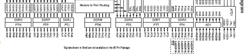
24 Important Peripherals 24
25 Computer Software Computer programs are known as software. A program is a sequence of instructions. There are at least three levels of software: 1. Kernel: is a program responsible for making the computer hardware perform the instructions that a programmer wrote. 2. Operating software: is responsible for memory management, exception services, and program execution control, such as: MacOS, Windows 95, 98, 2000, XP, Linux, UNIX 3. Application program: such as: word processor, spreadsheets, , text editor
26 Computer Software Microprocessor/Microcontroller Instructions/Languages Machine, Assembly, and High-Level Machine instructions: A sequence of binary digits which can be executed by the processor : [A] + [B] > A aba : [A] + 1 > A inca : 6 > A ldaa #06 Hard to understand, enter, debug, and maintain for human being A readable equivalent of what is performed is shown first A mnemonic for the machine instruction is shown second.
27 Assembly Language Defined by assembly language instructions An assembly instruction is a mnemonic representation of a machine instruction Mnemonic What it does (RTL) aba ; [A] + [B] > A deca ; [A] - 1 > A Assembly programs must be translated into machine instructions before it can be executed -- translated by an assembler There are two kinds of assemblers: native assembler and cross assembler. Programmers need to work on the program logic at a very low level and cannot achieve high productivity. 27
28 Assembly Language Example Loop1: ldx #Array1 ; Loads index register X with start address of Array1 ldy #Array2 ; Loads index register Y with start address of Array2 ldab #$0A ; Loads B accumulator with value 10 for counter Assembly Language Instructions Elements: Label: a defined location in the code used by compiler/assembler Opcode: descriptor of the operation to be performed Source and Destination: source and destination of operands (from where, to where) Where the next instruction comes from (usually the next instruction, increment PC)
29 Machine/Assembly Code Example line addr. machine code source code 1: 2: 2000 B ldaa $1000 3: 2003 BB 1001 adda $1001 4: 2006 BB 1002 adda $1002 5: A 1100 staa $1100 The example shows: The address where the machine code is to be stored in memory The machine code in hex The assembly code or source code with an assembler directive The assembler directive tells the assembler at what address to start storing the machine code
30 High-level Language Syntax of a high-level language is similar to English (?!) A translator is required to translate the program written in a high-level language -- done by a compiler. There are two types of compilers: native compiler and cross compiler. High-level languages allow the user to work on the program logic at higher level and achieve higher productivity. Source code A program written in assembly or high-level language Object code The output of an assembler or compiler
31 Machine/Assembly Code Example line addr. machine code source code 1: 2: 2000 B ldaa $1000 3: 2003 BB 1001 adda $1001 4: 2006 BB 1002 adda $1002 5: A 1100 staa $1100 The example shows: The address where the machine code is to be stored in memory The machine code in hex The assembly code or source code with an assembler directive The assembler directive tells the assembler at what address to start storing the machine code

32 Microcontroller Used for This Class MC9S12DP bit Microcontroller manufactured by Motorola/Freescale Includes: HCS12 CPU Core (speed 24 MHz) On-Chip Debug Interface 512K Flash, 14K RAM, 4K EEPROM 91 I/O Lines, ATD Module, Timer Module, PWM, SPI, SCI, IIC and CAN modules and PLL module Widely used in the automobile industry 32
33 How Widely Used? According to the U.S. Bureau of the Census, the resident population of the United States, projected to 05/11/11 is 311,331,964. Therefore, approximately 1 microcontroller for every 3 people in the US every year! 33

34 Application Brochure Finding This Stuff: Freescale 16-bit Microcontroller S12 and S12X S12D &WT_VENDOR=FREESCALE&WT_FILE_FORMAT=pdf&WT_ASSET=Documentation
35 HCS12 CPU Registers 7 A 0 7 B 0 15 D 0 15 X 0 15 Y 0 15 SP 0 15 PC 0 S X H I N Z V C 8-bit accumulator A and B or 16-bit double accumulator D Index register X Index register Y Stack pointer Program counter Figure 1.2 HCS12 CPU registers. Condition code register Carry Overflow Zero Negative I Interrupt mask Half-Carry (from bit 3) X Interrupt Mask Stop Disable Data Registers Two 8-bit, [A] and [B] OR One 16-bit, [D] Memory index registers Two general purpose, [X] and [Y] One stack pointer, [SP] Program Counter Instruction address, [PC] Condition Code Register Bits describing completed CPU operation or instruction results [C] or [CCR] 2510

36 Simple Processor Diagram Registers Interactions
37 Accumulator Based Machines All arithmetic or logic functions must go through the accumulator. Opcode (in the instruction register) relate the operation The destination is often explicit the accumulator. Load and store operations are use often. The accumulator sets the majority of condition code register bits. Index and Stack Pointer Registers These will be used often for addressing. There is expected to be a fixed stack and it will be used a lot
38 Condition Code Register Condition Code Register (CCR) (8-bit register) Used to keep track of the program execution status Control the execution of conditional instructions Enable the interrupt handling Most important for arithmetic S X H I N Z V C Interrupt Mask Interrupt Mask Zero Carry Stop disable Half-Carry Negative Overflow (from bit 3)
39 Condition Code Register (1 of 2) Carry Flag is set when and addition/subtraction generates a borrow/carry in/out of the highest bit position Applies to unsigned integers Overflow Flag is set when addition of two positive numbers results in a negative number and vice-versa. i.e. whenever the carry from the most significant bit and the second most significant bit differs Applies to signed integers Zero Flag is set when a particular operation leads to a result of zero Negative Flag is set whenever the most significant bit of the result of an operation is 1, i.e. result is negative 39
40 Condition Code Register (2 of 2) Interrupt Mask When set, all maskable interrupts are disabled (detailed explanation provided during lecture on interrupts) Half Carry Flag is set whenever there is a carry from the lower four bits to the upper four bits X Interrupt Mask Stop Set during the system reset (detailed explanation provided during lecture on interrupts) Clearing this bit keeps the processor in standby mode (detailed explanation provided during lecture on interrupts) 40
41 Memory Addressing Memory consists of a sequence of directly addressable locations. A location is referred to as an information unit. A memory location can be used to store data, instruction, and the status of peripheral devices. A memory location has two components: an address and its contents. Address Contents Figure 1.5 The components of a memory location Addresses in our microcontroller. For our processor, a 16-bit address. Each address reads one byte (8-bits), not a 16-bit word. Physical address range, 0 to 65,
42 Human Readable Addressing Leading characters are used to describe a number system Decimal: 1023 Binary: % Hex: $03FF (also common 0x03FF)
43 Transferring Data Address bus lines CPU Memory Data bus lines Figure 1.6 Transferring data between CPU and memory Data transfers between the CPU and the memory are done over the common buses: address bus and data bus. Notations: m[addr] represents the contents of a memory location, [reg] or reg refers to the contents of a register. For example, m[$20] refers to the contents of memory location at $20. [A] or A refers to the contents of accumulator A. 43
44 Addressing Modes A HCS12 instruction consists of one or two bytes of opcode and zero to five bytes of operand addressing information. Opcode bytes specify the operation to be performed by the CPU. For us, the first byte of a two-byte opcode is always $18. Addressing modes specify the operand to be operated on. The addressing mode may specify a value, a register, or a memory location to be used as an operand. 44
45 Addressing Mode Summary 45
46 Addressing Modes Inherent Immediate Direct Extended (or Extended Direct) Relative (or typically PC Relative) Indexed Indexed with constant offset Indexed with a data register (accumulator) offset Indexed with auto pre-/post-increment/decrement of index register Indexed-Indirect Indexed-Indirect with a constant and index register Indexed-Indirect with a D register and index register 46
47 Inherent Mode Instructions that use this mode do not use extra bytes to specify operands because the instructions either do not need operands or all operands are CPU registers. Examples nop inx deca ;no operation ;increment register X ;decrement register A Operands are implied by the opcode
48 Immediate Mode (use #) Operands for instructions that use immediate mode are included in the instruction. Example ldaa #$55 ; Load register A with the value $55, A $55 ldx #$1000 ; Load register X with the value $1000, X $1000 ldx #Array1 ; Loads index register X with start address of Array1 ldy #Array2 ; Loads index register Y with start address of Array2 ldab #$0A ; Loads B accumulator with value 10 The CPU does not access a memory address or register for operands
49 Direct Mode This mode can only specify memory locations in the range of (one byte address or two hex digits). Example ldaa $20 ;load register A with memory location $20 ; A ($0020) ldab $40 ;load register B with memory location $40 ; B ($0040) This mode uses only one byte to specify the operand address
50 Extended (Direct) Mode In this mode, the full 16-bit address is provided in the instruction (four hex digits). For example, ldaa $4000 ; load register A with memory location $4000 ; A ($4000) ldx $FE60 ; load register X with memory location $FE60 ; A ($FE60) lds $3C00 load the stack pointer to the default address This mode uses two bytes to specify the operand address
51 Relative Mode (1 of 2) Used only by branch instructions that change the PC Short and long conditional branch instructions use the relative mode. That s way it s also called PC-Relative addressing A short branch instructions consists of an 8-bit opcode and a signed 8-bit offset. The short relative mode can specify a range of -128 ~ A long branch instruction consists of an 8-bit opcode and a signed 16-bit offset. The range of the long relative mode is from ~
52 Relative Mode (2 of 2) For example, minus: bmi minus ; branch if minus ; if N=1, PC (PC) Rel ; else PC (PC) + 2 A programmer uses a label to specify the branch target and the assembler will figure out the actual branch offset (distance) from the instruction that follows the branch instruction
53 Addressing Mode Summary
54 Indexed Mode Overview This mode uses the sum of an index register (X, Y, or SP) and an offset to specify the address of an operand. The offset can be a 5-bit, 9-bit, or 16-bit signed value. The offset can be the value in accumulator A, B, or D. The PC may also be used as the index register for offset addressing, but it is not recommended. If offset is not needed, auto incrementing or decrementing of the index register can be performed. Automatic pre- or post-increment or pre- or post-decrement of the index registers by -1 to -8 or +1 to +8 are options. Indexed-Indirect addressing is unique as it generates the address of the address Indirect addressing with 16-bit offset or accumulator D as the offset is supported. A summary of indexed addressing modes is given in Table
55 Indexed Addressing Modes Table 1.3 Summary of indexed operations Postbyte code (xb) source code syntax Comments rr: 00 = X, 01 = Y, 10 = SP, 11 = PC rr0nnnnn 111rr0zs 111rr011 rr1pnnnn 111rr1aa 111rr111 r n,r -n,r n,r -n,r [n,r] n,-r n,+r n,rn,r+ A,r B,r D,r [D,r] 5-bit constant offset n = -16 to +15 r can be X, Y, SP, or PC Constant offset (9- or 16-bit signed) z: 0 = 9-bit with sign in LSB of postbyte (s) -256< n < = 16-bit 0 < n < if z = s = 1, 16-bit offset indexed-indirect (see below) r can be X, Y, SP, or PC 16-bit offset indexed-indirect 0 < n < rr can be X, Y, SP, or PC Auto pre-decrement/increment or auto post-decrement/increment; p = pre-(0) or post-(1), n = -8 to -1 or +1 to +8 r can be X, Y, or SP (PC not a valid choice) +8 = = = = 1000 Accumulator offset (unsigned 8-bit 0r 16-bit) aa: 00 = A 01 = B 10 = D (16-bit) 11 = see accumulator D offset indexed-indirect r can be X, Y, SP, or PC Accumulator D offset indexed-indirect r can be X, Y, SP, or PC 55
56 Indexed Addressing (1 of 3) 5-bit Constant Offset Indexed Addressing (IDX) The base index register can be X, Y, SP, or PC. The range of the offset is from -16 to +15. Examples ldaa 0,X ; load A with memory location (X + 0) stab -8,X ; store B at memory location (X - 8) 9-bit Constant Offset Indexed Addressing (IDX1) The base index register can be X, Y, SP, or PC. The range of the offset is from -256 to Examples ldaa $FF,X ; load A with memory location (X + 255) ldab -20,Y ; load B with memory location (Y - 20) 56
57 Indexed Addressing (2 of 3) 16-bit Constant Offset Indexed Addressing (IDX2) The base index register can be X, Y, SP, or PC. This mode allows access any location in the 64-KB range. Examples ldaa 2000,X ; load A with memory location (X ) staa $4000,Y ; store A at memory location (Y + $4000) 57
58 Indexed Addressing (3 of 3) 16-bit Constant Indirect Indexed Addressing ( [D,IDX] OR [IDX2] ) A 16-bit offset is added to the base index register to form the address of a memory location that contains a pointer to the memory location affected by the instruction. The square brackets distinguish this addressing mode from the 16- bit constant offset indexing. Example, ldaa [10,X] ; load A with memory location m[m[x + 10]] staa [D,Y] ; store A at memory location m[m[y + D]] Generate the address containing the address desired. Useful for using a table of pointers and the pointers can change in time (using jump tables) 58
59 Auto Pre/Post-Decrement/Increment Indexed Addressing The index register can be incremented or decremented by an integer value either before or after indexing taking place. The base index register can be X, Y, or SP. The value to be incremented or decremented is in the ranges -8 thru -1 or 1 thru 8. The index register retains the changed value after indexing. Examples staa 1,-Y ; store A at memory location (Y-1), Y Y-1 staa 1,Y- ; store A at memory location (Y), Y Y-1 ldx 2,+Y ; load X with memory location (Y+2), Y Y+2 ldx 2,Y+ ; load X with memory location (Y), Y Y+2 59
60 Accumulator Offset Indexed Addressing The effective address of the operand is the sum of the accumulator and the base index register. The base register can be X, Y, SP, or PC. The accumulator can be the 8-bit A or B or the 16-bit accumulator D. Example ldaa B,X ; load A with memory location (X + B) stab A,Y ; store B at memory location (Y + A), 60
61 Example Accumulator D Indirect Indexed Addressing The value in D is added to the value in the base index register to form the address of the memory location that contains the address to the memory location affected by the instruction. The square brackets distinguish this addressing mode from accumulator D offset indexing. jmp [D,PC] ; load PC with (PC + D) go1 dc.w target1 go2 dc.w target2 go3 dc.w target3 target1. target2 target3. 61


62 Addressing Mode Summary 62
63 HCS12 Instruction Types LOAD and STORE LOAD copies the contents of a memory location or places an immediate value into an accumulator or a CPU register. STORE save the contents of a CPU register into a memory location. TRANSFER and EXCHANGE TRANSFER moves the contents of one register into another EXCHANGE swaps the contents of one register with another MOVE MOVE moves source bytes or words to defined destinations sources may be immediate values, index registers addressed memory, or memory locations destinations may be index registers addressed memory or memory locations 63
64 HCS12 Instruction Types (cont) ADD and SUBTRACT ADD register value with addressed memory. SUBTRACT addressed memory from a register value BCD operations perform binary coded decimal adjustments and additions INC and DEC INC increments memory locations or registers DEC decrements memory locations or registers COMPARE and TEST Operations to set the condition code registers BOOLEAN LOGIC FUNCTIONS AND, OR, and exclusive OR data registers with immediate values or memory locations 64
65 HCS12 Instruction Types (cont) CLEAR, COMPLEMENT and NEGATE MULTIPLY and DIVIDE BIT LEVEL TEST, SET and CLEAR SHIFT and ROTATE SHIFT register values right or left with zero fill or sign extend ROTATE register values circularly within the register BRANCH INSTRUCTIONS change program flow based on condition code values Includes looping primitives JUMP and SUBROUTINE control flow commands 65
66 HCS12 Instruction Types (cont) INTERRUPT INDEX MANIPULATION STACK OPERATIONS CONDITION CODE MANIPULATION STOP and WAIT See section 5 of the S12CPUV2.PDF Reference Manual Reference Manual in HW Solution Web Site See Section 6 for an instruction glossary (one or more pages per instruction)
67 Include or Header Files mc9s12dp256.h The C header file fore the specific processor to be included whenever compiling C code mc9s12dp256.s An assembly language source code file with all common peripheral register names equated to their correct locations. If and when specific internal CPU addresses locations are required, they can be found in this file. Either cut and paste what you need or include the entire file. 67
68 Load and Store Instructions 68
69 Transfer and Exchange Instructions Mnemonic Function Operation TAB Transfer A to B (A) B TAP Transfer A to CCR (A) CCR TBA Transfer B to A (B) A TFR Transfer register to register (A, B, CCR, D, X, Y, or SP) A, B, CCR, D, X, Y, or SP TPA Transfer CCR to A (CCR) A TSX Transfer SP to X (SP) X TSY Transfer SP to Y (SP) Y TXS Transfer X to SP (X) SP TYS Transfer Y to SP (Y) SP Mnemonic Function Operation EXG Exchange register to register (A, B, CCR, D, X, Y, or SP) A, B, CCR, D, X, Y, or SP) XGDX Exchange D with X (D) (X) XGDY Exchange D with Y (D) (Y) Mnemonic Function Operation 2510 SEX Sign extend 8-Bit operand (A, B, or CCR) D, X, Y, or SP 69
70 Move Instructions Move Instructions Mnemonic Function Operation MOVB Move byte (8-bit) (M 1 ) (M 2 ) MOVW Move word (16-bit) (M 1 :M 1 +1) (M 2 :M 2 +1)
71 Add and Subtract Instructions 71
72 Instruction Tables Table information from the manual/textbook 72
73 Instruction Tables Instruction Table and Timing See Appendix A of the S12CPUV2.PDF Reference Manual Processor Cycles Needed or CPI
74 Instruction Execution Cycle Instruction Execution Cycle One or more read cycles to fetch instruction opcode bytes and addressing information One or more read cycles to fetch the memory operand(s) (optional) Perform the operation specified by the opcode One or more write cycles to write back the result to either a register or a memory location (optional) 74
75 Instruction Queue Instruction Queue The HCS12 executes one instruction at a time and many instructions take several clock cycles to complete. When the CPU is performing the operation, it does not need to access memory. The HCS12 prefetches instructions when the CPU is not accessing memory to speedup the instruction execution process. There are two 16-bit queue stages and one 16-bit buffer. Unless buffering is required, program information is first queued in stage 1, and then advanced to stage 2 for execution. 75
Introduction to Embedded Systems and Chapter 1: Introduction to HCS12/MC9S12. EE383: Introduction to Embedded Systems University of Kentucky
 Introduction to Embedded Systems and Chapter 1: Introduction to HCS12/MC9S12 EE383: Introduction to Embedded Systems University of Kentucky Samir Rawashdeh With slides based on material by H. Huang Delmar
 Chapter 1 Microprocessor architecture ECE 3120 Dr. Mohamed Mahmoud http://iweb.tntech.edu/mmahmoud/ mmahmoud@tntech.edu Outline 1.1 Computer hardware organization 1.1.1 Number System 1.1.2 Computer hardware
Microcontrollers. Microcontroller
 Microcontrollers Microcontroller A microprocessor on a single integrated circuit intended to operate as an embedded system. As well as a CPU, a microcontroller typically includes small amounts of RAM and
Chapter 1. Microprocessor architecture ECE Dr. Mohamed Mahmoud.
 Chapter 1 Microprocessor architecture ECE 3130 Dr. Mohamed Mahmoud The slides are copyright protected. It is not permissible to use them without a permission from Dr Mahmoud http://www.cae.tntech.edu/~mmahmoud/
ME4447/6405. Microprocessor Control of Manufacturing Systems and Introduction to Mechatronics. Instructor: Professor Charles Ume LECTURE 7
 ME4447/6405 Microprocessor Control of Manufacturing Systems and Introduction to Mechatronics Instructor: Professor Charles Ume LECTURE 7 Reading Assignments Reading assignments for this week and next
2. Arithmetic Instructions addition, subtraction, multiplication, divison (HCS12 Core Users Guide, Sections 4.3.4, and ).
.") AS12 Assembler Directives A Summary of 9S12 instructions Disassembly of 9S12 op codes Huang Section 1.8, Chapter 2 MC9S12 V1.5 Core User Guide Version 1.2, Section 12 o A labels is a name assigned the
AS12 Assembler Directives A Summary of 9S12 instructions Disassembly of 9S12 op codes Huang Section 1.8, Chapter 2 MC9S12 V1.5 Core User Guide Version 1.2, Section 12 o A labels is a name assigned the
MC9S12 Assembler Directives A Summary of MC9S12 Instructions Disassembly of MC9S12 op codes. Summary of HCS12 addressing modes ADDRESSING MODES
 MC9S12 Assembler Directives A Summary of MC9S12 Instructions Disassembly of MC9S12 op codes o Review of Addressing Modes o Which branch instruction to use (signed vs unsigned) o Using X and Y registers
Disassembly of MC9S12 op codes Decimal, Hexadecimal and Binary Numbers
 Disassembly of MC9S12 op codes Decimal, Hexadecimal and Binary Numbers o How to disassemble an MC9S12 instruction sequence o Binary numbers are a code and represent what the programmer intends for the
Disassembly of MC9S12 op codes Decimal, Hexadecimal and Binary Numbers
 Disassembly of MC9S12 op codes Decimal, Hexadecimal and Binary Numbers o How to disassemble an MC9S12 instruction sequence o Binary numbers are a code and represent what the programmer intends for the
Mark II Aiken Relay Calculator
 Introduction to Embedded Microcomputer Systems Lecture 6.1 Mark II Aiken Relay Calculator 2.12. Tutorial 2. Arithmetic and logical operations format descriptions examples h 8-bit unsigned hexadecimal $00
EE 5340/7340 Motorola 68HC11 Microcontroler Lecture 1. Carlos E. Davila, Electrical Engineering Dept. Southern Methodist University
 EE 5340/7340 Motorola 68HC11 Microcontroler Lecture 1 Carlos E. Davila, Electrical Engineering Dept. Southern Methodist University What is Assembly Language? Assembly language is a programming language
Chapter 7 Central Processor Unit (S08CPUV2)
") Chapter 7 Central Processor Unit (S08CPUV2) 7.1 Introduction This section provides summary information about the registers, addressing modes, and instruction set of the CPU of the HCS08 Family. For a more
Chapter 7 Central Processor Unit (S08CPUV2) 7.1 Introduction This section provides summary information about the registers, addressing modes, and instruction set of the CPU of the HCS08 Family. For a more
EE 308: Microcontrollers
 EE 308: Microcontrollers AVR Architecture Aly El-Osery Electrical Engineering Department New Mexico Institute of Mining and Technology Socorro, New Mexico, USA January 23, 2018 Aly El-Osery (NMT) EE 308:
S12CPUV2. Reference Manual HCS12. Microcontrollers. S12CPUV2/D Rev. 0 7/2003 MOTOROLA.COM/SEMICONDUCTORS
 HCS12 Microcontrollers /D Rev. 0 7/2003 MOTOROLA.COM/SEMICONDUCTORS To provide the most up-to-date information, the revision of our documents on the World Wide Web will be the most current. Your printed
CPU12 REFERENCE MANUAL
 CPU12 REFERENCE MANUAL Motorola reserves the right to make changes without further notice to any products herein. Motorola makes no warranty, representation or guarantee regarding the suitability of its
ELECTRICAL AND COMPUTER ENGINEERING DEPARTMENT, OAKLAND UNIVERSITY ECE-470/570: Microprocessor-Based System Design Fall 2014.
 ECE-47/57: Microprocessor-Based System Design Fall 214 Notes - Unit 3 OVERVIEW OF THE HCS12 MICROCONTROLLER The HCS12 is a family of Freescale microcontrollers (MCUs) targeted to automotive and process
ECED3204: Microprocessor Part I--Introduction
 ECED3204: Microprocessor Part I--Introduction Jason J. Gu Department of 1 Outline i. Computer ii. Processor iii. Embedded System iv. Memory v. Program Execution VI. VII. VIII. IX. AVR AVR Memory AVR CPU
Microcontrollers and the Freescale/Motorola HC11
 Microcontrollers and the Freescale/Motorola HC11 What is a microcontroller? A computer on a chip used to control electronic devices A microprocessor Usually not cutting edge (4-bit to 32-bit) Dependable
ECE331 Handout 3- ASM Instructions, Address Modes and Directives
 ECE331 Handout 3- ASM Instructions, Address Modes and Directives ASM Instructions Functional Instruction Groups Data Transfer/Manipulation Arithmetic Logic & Bit Operations Data Test Branch Function Call
Menu Computer Organization Programming Model for the an example microprocessors (the G-CPU & Motorola 68HC11) Assembly Programming Look into my...
 Assembly Programming Look into my...") Menu Computer Organization Programming Model for the an example microprocessors (the G-CPU & Motorola 68HC11) Assembly Programming Look into my... See examples on web: DirAddr.asm, ExtAddr.asm, IndAddr.asm,
Menu Computer Organization Programming Model for the an example microprocessors (the G-CPU & Motorola 68HC11) Assembly Programming Look into my... See examples on web: DirAddr.asm, ExtAddr.asm, IndAddr.asm,
538 Lecture Notes Week 2
 538 Lecture Notes Week 2 (Sept. 13, 2017) 1/15 Announcements 538 Lecture Notes Week 2 Labs begin this week. Lab 1 is a one-week lab. Lab 2 (starting next week) is a two-week lab. 1 Answers to last week's
Accumulator and memory instructions 1. Loads, stores, and transfers 2. Arithmetic operations 3. Multiply and divide 4. Logical operations 5. Data test
 HC11 Instruction Set Instruction classes 1. 2. 3. 4. Accumulator and Memory Stack and Index Register Condition Code Register Program control instructions 2 1 Accumulator and memory instructions 1. Loads,
Most of the HC12 s instructions access data in memory There are several ways for the HC12 to determine which address to access
 HC12 Addressing Modes Instruction coding and execution o Inherent, Extended, Direct, Immediate, Indexed, and Relative Modes o Summary of MC9S12 Addressing Modes o Using X and Y registers as pointers o
Microcomputer Architecture and Programming
 IUST-EE (Chapter 1) Microcomputer Architecture and Programming 1 Outline Basic Blocks of Microcomputer Typical Microcomputer Architecture The Single-Chip Microprocessor Microprocessor vs. Microcontroller
8051 Overview and Instruction Set
 8051 Overview and Instruction Set Curtis A. Nelson Engr 355 1 Microprocessors vs. Microcontrollers Microprocessors are single-chip CPUs used in microcomputers Microcontrollers and microprocessors are different
Wed. Aug 23 Announcements
 Wed. Aug 23 Announcements Professor Office Hours 1:30 to 2:30 Wed/Fri EE 326A You should all be signed up for piazza Most labs done individually (if not called out in the doc) Make sure to register your
538 Lecture Notes Week 1
 538 Clowes Lecture Notes Week 1 (Sept. 6, 2017) 1/10 538 Lecture Notes Week 1 Announcements No labs this week. Labs begin the week of September 11, 2017. My email: kclowes@ryerson.ca Counselling hours:
Microprocessors/Microcontrollers
 Microprocessors/Microcontrollers A central processing unit (CPU) fabricated on one or more chips, containing the basic arithmetic, logic, and control elements of a computer that are required for processing
Architecture & Instruction set of 8085 Microprocessor and 8051 Micro Controller
 of 8085 microprocessor 8085 is pronounced as "eighty-eighty-five" microprocessor. It is an 8-bit microprocessor designed by Intel in 1977 using NMOS technology. It has the following configuration 8-bit
Exam I Review February 2017
 Exam I Review February 2017 Binary Number Representations Conversion of binary to hexadecimal and decimal. Convert binary number 1000 1101 to hexadecimal: Make groups of 4 bits to convert to hexadecimal,
N bit is set if result of operation in negative (MSB = 1) Z bit is set if result of operation is zero (All bits = 0)
 Z bit is set if result of operation is zero (All bits = 0)") Addition and Subtraction of Hexadecimal Numbers. Setting the C (Carry), V (Overflow), N (Negative) and Z (Zero) bits How the C, V, N and Z bits of the CCR are changed Condition Code Register Bits N, Z,
Addition and Subtraction of Hexadecimal Numbers. Setting the C (Carry), V (Overflow), N (Negative) and Z (Zero) bits How the C, V, N and Z bits of the CCR are changed Condition Code Register Bits N, Z,
HC11 Instruction Set
 HC11 Instruction Set Instruction classes 1. Accumulator and Memory 2. Stack and Index Register 3. Condition Code Register 4. Program control instructions CMPE12 Summer 2009 19-2 1 Accumulator and memory
Introduction to the 9S12 Microcontroller
 Introduction to the 9S12 Microcontroller o Harvard architecture and Princeton architecture o Memory map for a Princeton architecture microprocessor o 68HC12 Address Space o 68HC12 ALU o 68HC12 Programming
COMP2121: Microprocessors and Interfacing. Instruction Set Architecture (ISA)
") COMP2121: Microprocessors and Interfacing Instruction Set Architecture (ISA) http://www.cse.unsw.edu.au/~cs2121 Lecturer: Hui Wu Session 2, 2017 1 Contents Memory models Registers Data types Instructions
COMP2121: Microprocessors and Interfacing Instruction Set Architecture (ISA) http://www.cse.unsw.edu.au/~cs2121 Lecturer: Hui Wu Session 2, 2017 1 Contents Memory models Registers Data types Instructions
Introduction to Microcontrollers
 Motorola M68HC11 Specs Assembly Programming Language BUFFALO Topics of Discussion Microcontrollers M68HC11 Package & Pinouts Accumulators Index Registers Special Registers Memory Map I/O Registers Instruction
FIFTH SEMESTER DIPLOMA EXAMINATION IN ENGINEERING/ TECHNOLOGY-MARCH 2014 EMBEDDED SYSTEMS (Common for CT,CM) [Time: 3 hours] (Maximum marks : 100)
![FIFTH SEMESTER DIPLOMA EXAMINATION IN ENGINEERING/ TECHNOLOGY-MARCH 2014 EMBEDDED SYSTEMS (Common for CT,CM) [Time: 3 hours] (Maximum marks : 100)](/thumbs/76/73351884.jpg "FIFTH SEMESTER DIPLOMA EXAMINATION IN ENGINEERING/ TECHNOLOGY-MARCH 2014 EMBEDDED SYSTEMS (Common for CT,CM) [Time: 3 hours] (Maximum marks : 100)") (Revision-10) FIFTH SEMESTER DIPLOMA EXAMINATION IN ENGINEERING/ TECHNOLOGY-MARCH 2014 EMBEDDED SYSTEMS (Common for CT,CM) [Time: 3 hours] (Maximum marks : 100) PART-A (Maximum marks : 10) I. Answer all
(Revision-10) FIFTH SEMESTER DIPLOMA EXAMINATION IN ENGINEERING/ TECHNOLOGY-MARCH 2014 EMBEDDED SYSTEMS (Common for CT,CM) [Time: 3 hours] (Maximum marks : 100) PART-A (Maximum marks : 10) I. Answer all
Introduction to Programming
 Introduction to Programming Chapter 2 Microcontrollers Objectives Describe the difference between source code and machine code. Define opcode, operand, and address of an operand. Explain the purpose of
Introduction to Computers - Chapter 4
 Introduction to Computers - Chapter 4 Since the invention of the transistor and the first digital computer of the 1940s, computers have been increasing in complexity and performance; however, their overall
Addition and Subtraction of Hexadecimal Numbers Simple assembly language programming
 Addition and Subtraction of Hexadecimal Numbers Simple assembly language programming o A simple Assembly Language Program o Assembling an Assembly Language Program o Simple 9S12 programs o Hex code generated
EE 3170 Microcontroller Applications
 Q. 3.9 of HW3 EE 37 Microcontroller Applications (a) (c) (b) (d) Midterm Review: Miller Chapter -3 -The Stuff That Might Be On the Exam D67 (e) (g) (h) CEC23 (i) (f) (j) (k) (l) (m) EE37/CC/Lecture-Review
A Simple MC9S12 Program
 A Simple MC9S12 Program All programs and data must be placed in memory between address 0x1000 and 0x3BFF. For our programs we will put the first instruction at 0x2000, and the first data byte at 0x1000
COSC 243. Instruction Sets And Addressing Modes. Lecture 7&8 Instruction Sets and Addressing Modes. COSC 243 (Computer Architecture)
") COSC 243 Instruction Sets And Addressing Modes 1 Overview This Lecture Source Chapters 12 & 13 (10 th editition) Textbook uses x86 and ARM (we use 6502) Next 2 Lectures Assembly language programming 2
COSC 243 Instruction Sets And Addressing Modes 1 Overview This Lecture Source Chapters 12 & 13 (10 th editition) Textbook uses x86 and ARM (we use 6502) Next 2 Lectures Assembly language programming 2
COMPUTER ORGANIZATION & ARCHITECTURE
 COMPUTER ORGANIZATION & ARCHITECTURE Instructions Sets Architecture Lesson 5a 1 What are Instruction Sets The complete collection of instructions that are understood by a CPU Can be considered as a functional
LECTURE #21: G-CPU & Assembly Code EEL 3701: Digital Logic and Computer Systems Based on lecture notes by Dr. Eric M. Schwartz
 LECTURE #21: G-CPU & Assembly Code EEL 3701: Digital Logic and Computer Systems Based on lecture notes by Dr. Eric M. Schwartz G-CPU Important Notes (see Schwartz s lecture for a general overview) - The
Fredrick M. Cady. Assembly and С Programming forthefreescalehcs12 Microcontroller. шт.
 SECOND шт. Assembly and С Programming forthefreescalehcs12 Microcontroller Fredrick M. Cady Department of Electrical and Computer Engineering Montana State University New York Oxford Oxford University
History of the Microprocessor. ECE/CS 5780/6780: Embedded System Design. Microcontrollers. First Microprocessors. MC9S12C32 Block Diagram
 History of the Microprocessor ECE/CS 5780/6780: Embedded System Design Chris J. Myers Lecture 1: 68HC12 In 1968, Bob Noyce and Gordon Moore left Fairchild Semiconductor and formed Integrated Electronics
CHAPTER 4 MARIE: An Introduction to a Simple Computer
 CHAPTER 4 MARIE: An Introduction to a Simple Computer 4.1 Introduction 177 4.2 CPU Basics and Organization 177 4.2.1 The Registers 178 4.2.2 The ALU 179 4.2.3 The Control Unit 179 4.3 The Bus 179 4.4 Clocks
1. Memory Mapped Systems 2. Adding Unsigned Numbers
 1 Memory Mapped Systems 2 Adding Unsigned Numbers 1 1 Memory Mapped Systems Our system uses a memory space Address bus is 16-bit locations Data bus is 8-bit 2 Adding Unsigned Numbers 2 Our system uses
UNIT-II. Part-2: CENTRAL PROCESSING UNIT
 Page1 UNIT-II Part-2: CENTRAL PROCESSING UNIT Stack Organization Instruction Formats Addressing Modes Data Transfer And Manipulation Program Control Reduced Instruction Set Computer (RISC) Introduction:
Grundlagen Microcontroller Processor Core. Günther Gridling Bettina Weiss
 Grundlagen Microcontroller Processor Core Günther Gridling Bettina Weiss 1 Processor Core Architecture Instruction Set Lecture Overview 2 Processor Core Architecture Computes things > ALU (Arithmetic Logic
Computer Organization
 INF 101 Fundamental Information Technology Computer Organization Assistant Prof. Dr. Turgay ĐBRĐKÇĐ Course slides are adapted from slides provided by Addison-Wesley Computing Fundamentals of Information
Programming the Motorola MC68HC11 Microcontroller
 Programming the Motorola MC68HC11 Microcontroller COMMON PROGRAM INSTRUCTIONS WITH EXAMPLES aba Add register B to register A Similar commands are abx aby aba add the value in register B to the value in
ECE 372 Microcontroller Design Basic Assembly Programming. ECE 372 Microcontroller Design Basic Assembly Programming
 For Loop Example: for(j=0; j
Introduction to Microcomputer Systems Addressing modes
 Dept. of Computer Science and Engineering Introduction to Microcomputer Systems Overview Addressing mode Source form Abbreviation Description Inherent INST (no externally supplied operands) INH Immediate
Microcontroller Systems
 µcontroller systems 1 / 43 Microcontroller Systems Engineering Science 2nd year A2 Lectures Prof David Murray david.murray@eng.ox.ac.uk www.robots.ox.ac.uk/ dwm/courses/2co Michaelmas 2014 µcontroller
CodeWarrior. Microcomputer Architecture and Interfacing Colorado School of Mines Professor William Hoff
 CodeWarrior 1 Assembler An assembler is a program that translates assembly language into machine code. Machine code are the numbers that the CPU recognizes as instructions. $B6 $10 $00 Assembly language
Internal architecture of 8086
 Case Study: Intel Processors Internal architecture of 8086 Slide 1 Case Study: Intel Processors FEATURES OF 8086 It is a 16-bit μp. 8086 has a 20 bit address bus can access up to 220 memory locations (1
MOXSYN. General Description. Features. Symbol
 MOXSYN C68MX11 CPU General Description The C68MX11 CPU core is based on the Motorola M68HC11 microcontroller controller, but has an enhanced full 16 bit architecture, thus requiring less clock cycles for
INTRODUCTION TO MICROPROCESSORS
 INTRODUCTION TO MICROPROCESSORS Richa Upadhyay Prabhu NMIMS s MPSTME richa.upadhyay@nmims.edu January 7, 2016 Richa Upadhyay Prabhu (MPSTME) INTRODUCTION January 7, 2016 1 / 63 Course Design Prerequisite:
Moodle WILLINGDON COLLEGE SANGLI (B. SC.-II) Digital Electronics
 Digital Electronics") Moodle 4 WILLINGDON COLLEGE SANGLI (B. SC.-II) Digital Electronics Advanced Microprocessors and Introduction to Microcontroller Moodle developed By Dr. S. R. Kumbhar Department of Electronics Willingdon
Moodle 4 WILLINGDON COLLEGE SANGLI (B. SC.-II) Digital Electronics Advanced Microprocessors and Introduction to Microcontroller Moodle developed By Dr. S. R. Kumbhar Department of Electronics Willingdon
Introduction to Microprocessor
 Introduction to Microprocessor The microprocessor is a general purpose programmable logic device. It is the brain of the computer and it performs all the computational tasks, calculations data processing
COMP3221: Microprocessors and. and Embedded Systems. Instruction Set Architecture (ISA) What makes an ISA? #1: Memory Models. What makes an ISA?
 What makes an ISA? #1: Memory Models. What makes an ISA?") COMP3221: Microprocessors and Embedded Systems Lecture 2: Instruction Set Architecture (ISA) http://www.cse.unsw.edu.au/~cs3221 Lecturer: Hui Wu Session 2, 2005 Instruction Set Architecture (ISA) ISA is
COMP3221: Microprocessors and Embedded Systems Lecture 2: Instruction Set Architecture (ISA) http://www.cse.unsw.edu.au/~cs3221 Lecturer: Hui Wu Session 2, 2005 Instruction Set Architecture (ISA) ISA is
b. List different system buses of 8085 microprocessor and give function of each bus. (8) Answer:
 Answer:") Q.2 a. Discuss and differentiate between a Microprocessor and a Microcontroller. Microprocessor is an IC which has only the CPU inside them i.e. only the processing powers such as Intel s Pentium 1,2,3,4,
Q.2 a. Discuss and differentiate between a Microprocessor and a Microcontroller. Microprocessor is an IC which has only the CPU inside them i.e. only the processing powers such as Intel s Pentium 1,2,3,4,
CPU: SOFTWARE ARCHITECTURE INSTRUCTION SET (PART
 General Introduction CPU: SOFTWARE ARCHITECTURE INSTRUCTION SET (PART 1) General Introduction (1/5): On Instructions Instruction operate with data or with the flow of the program The following information
 Question Bank Part-A UNIT I- THE 8086 MICROPROCESSOR 1. What is microprocessor? A microprocessor is a multipurpose, programmable, clock-driven, register-based electronic device that reads binary information
Table 1: Mnemonics Operations Dictionary. Add Accumulators Add B to Y. Add with carry to B. Add Memory to B. Add 16-bit to D And B with Memory
 Table 1: Mnemonics s Dictionary ABA ABX ABY ADCA ADCB ADDA ADDB ADDD ANDA ANDB ASL ASLA ASLB ASLD ASR ASRA ASRB BCC BCLR BCS BEQ BGE BGT BHI BHS BITA BITB BLE BLO BLS BLT Add Accumulators Add B to X Add
538 Lecture Notes Week 5
 538 Lecture Notes Week 5 (October 4, 2017) 1/18 538 Lecture Notes Week 5 Announements Midterm: Tuesday, October 25 Answers to last week's questions 1. With the diagram shown for a port (single bit), what
Assembly Language Programming of 8085
 Assembly Language Programming of 8085 Topics 1. Introduction 2. Programming model of 8085 3. Instruction set of 8085 4. Example Programs 5. Addressing modes of 8085 6. Instruction & Data Formats of 8085
538 Lecture Notes Week 5
 538 Lecture Notes Week 5 (Sept. 30, 2013) 1/15 538 Lecture Notes Week 5 Answers to last week's questions 1. With the diagram shown for a port (single bit), what happens if the Direction Register is read?
CHAPTER 8. Solutions for Exercises
 CHAPTER 8 Solutions for Exercises E8.1 The number of bits in the memory addresses is the same as the address bus width, which is 20. Thus the number of unique addresses is 2 20 = 1,048,576 = 1024 1024
Lecture 6 Assembly Programming: Branch & Iteration
 CPE 390: Microprocessor Systems Spring 2018 Lecture 6 Assembly Programming: Branch & Iteration Bryan Ackland Department of Electrical and Computer Engineering Stevens Institute of Technology Hoboken, NJ
The Central Processing Unit
 The Central Processing Unit All computers derive from the same basic design, usually referred to as the von Neumann architecture. This concept involves solving a problem by defining a sequence of commands
CS 101, Mock Computer Architecture
 CS 101, Mock Computer Architecture Computer organization and architecture refers to the actual hardware used to construct the computer, and the way that the hardware operates both physically and logically
VARDHAMAN COLLEGE OF ENGINEERING (AUTONOMOUS) Shamshabad, Hyderabad
 Shamshabad, Hyderabad") Introduction to MS-DOS Debugger DEBUG In this laboratory, we will use DEBUG program and learn how to: 1. Examine and modify the contents of the 8086 s internal registers, and dedicated parts of the memory
Introduction to MS-DOS Debugger DEBUG In this laboratory, we will use DEBUG program and learn how to: 1. Examine and modify the contents of the 8086 s internal registers, and dedicated parts of the memory
1. INTRODUCTION TO MICROPROCESSOR AND MICROCOMPUTER ARCHITECTURE:
 1. INTRODUCTION TO MICROPROCESSOR AND MICROCOMPUTER ARCHITECTURE: A microprocessor is a programmable electronics chip that has computing and decision making capabilities similar to central processing unit
MC9S12 Address Space
 MC9S12 Address Space MC9S12 has 16 address lines MC9S12 can address 2 16 distinct locations For MC9S12, each location holds one byte (eight bits) MC9S12 can address 2 16 bytes 2 16 = 65536 2 16 = 2 6 2
Computer Organization CS 206 T Lec# 2: Instruction Sets
 Computer Organization CS 206 T Lec# 2: Instruction Sets Topics What is an instruction set Elements of instruction Instruction Format Instruction types Types of operations Types of operand Addressing mode
AVR ISA & AVR Programming (I) Lecturer: Sri Parameswaran Notes by: Annie Guo
 Lecturer: Sri Parameswaran Notes by: Annie Guo") AVR ISA & AVR Programming (I) Lecturer: Sri Parameswaran Notes by: Annie Guo 1 Lecture Overview AVR ISA AVR Instructions & Programming (I) Basic construct implementation 2 Atmel AVR 8-bit RISC architecture
AVR ISA & AVR Programming (I) Lecturer: Sri Parameswaran Notes by: Annie Guo 1 Lecture Overview AVR ISA AVR Instructions & Programming (I) Basic construct implementation 2 Atmel AVR 8-bit RISC architecture
8086 INTERNAL ARCHITECTURE
 8086 INTERNAL ARCHITECTURE Segment 2 Intel 8086 Microprocessor The 8086 CPU is divided into two independent functional parts: a) The Bus interface unit (BIU) b) Execution Unit (EU) Dividing the work between
EXPERIMENT NO. 1 THE MKT 8085 MICROPROCESSOR TRAINER
 OBJECT: EXPERIMENT NO. 1 THE MKT 8085 MICROPROCESSOR TRAINER To understand the structure and operating instruction of the microprocessor trainer. INTRODUCTION: The MKT 8085 is a single-board microcomputer,
Addition and Subtraction of Hexadecimal Numbers Simple assembly language programming
 Addition and Subtraction of Hexadecimal Numbers Simple assembly language programming o A simple Assembly Language Program o Assembling an Assembly Language Program o Simple 9S12 programs o Hex code generated
COMP2121: Microprocessors and Interfacing. Introduction to Microprocessors
 COMP2121: Microprocessors and Interfacing Introduction to Microprocessors http://www.cse.unsw.edu.au/~cs2121 Lecturer: Hui Wu Session 2, 2017 1 1 Contents Processor architectures Bus Memory hierarchy 2
Computer Architecture 2/26/01 Lecture #
 Computer Architecture 2/26/01 Lecture #9 16.070 On a previous lecture, we discussed the software development process and in particular, the development of a software architecture Recall the output of the
The Instruction Set. Chapter 5
 The Instruction Set Architecture Level(ISA) Chapter 5 1 ISA Level The ISA level l is the interface between the compilers and the hardware. (ISA level code is what a compiler outputs) 2 Memory Models An
Basic Concepts COE 205. Computer Organization and Assembly Language Dr. Aiman El-Maleh
 Basic Concepts COE 205 Computer Organization and Assembly Language Dr. Aiman El-Maleh College of Computer Sciences and Engineering King Fahd University of Petroleum and Minerals [Adapted from slides of
CS/ECE 5780/6780: Embedded System Design
 CS/ECE 5780/6780: Embedded System Design John Regehr Lecture 2: 68HC12 Architecture & Lab 1 Introduction Duff s Device void foo (int x, int *y, int *z) { switch (x % 8) { case 0: do { *y++ = *z++; case
Microcontrollers. 2IN60: Real-time Architectures (for automotive systems) Mike Holenderski,
 Mike Holenderski,") Microcontrollers 2IN60: Real-time Architectures (for automotive systems) Goals for this slide set Describe the architecture of a microcontroller Explain the purpose of an Instruction Set Architecture and
Microcontrollers 2IN60: Real-time Architectures (for automotive systems) Goals for this slide set Describe the architecture of a microcontroller Explain the purpose of an Instruction Set Architecture and
Lecture 2 Microcomputer Organization: Fig.1.1 Basic Components of Microcomputer
 Lecture 2 Microcomputer Organization: As discussed in previous lecture microprocessor is a central processing unit (CPU) with its related timing functions on a single chip. A microprocessor combined with
Instruction Sets: Characteristics and Functions Addressing Modes
 Instruction Sets: Characteristics and Functions Addressing Modes Chapters 10 and 11, William Stallings Computer Organization and Architecture 7 th Edition What is an Instruction Set? The complete collection
8051 Microcontrollers
 8051 Microcontrollers Richa Upadhyay Prabhu NMIMS s MPSTME richa.upadhyay@nmims.edu March 8, 2016 Controller vs Processor Controller vs Processor Introduction to 8051 Micro-controller In 1981,Intel corporation
AVR ISA & AVR Programming (I) Lecturer: Sri Parameswaran Notes by: Annie Guo
 Lecturer: Sri Parameswaran Notes by: Annie Guo") AVR ISA & AVR Programming (I) Lecturer: Sri Parameswaran Notes by: Annie Guo 1 Lecture Overview AVR ISA AVR Instructions & Programming (I) Basic construct implementation 2 Atmel AVR 8-bit RISC architecture
AVR ISA & AVR Programming (I) Lecturer: Sri Parameswaran Notes by: Annie Guo 1 Lecture Overview AVR ISA AVR Instructions & Programming (I) Basic construct implementation 2 Atmel AVR 8-bit RISC architecture
The CPU and Memory. How does a computer work? How does a computer interact with data? How are instructions performed? Recall schematic diagram:
 The CPU and Memory How does a computer work? How does a computer interact with data? How are instructions performed? Recall schematic diagram: 1 Registers A register is a permanent storage location within
MicroProcessor. MicroProcessor. MicroProcessor. MicroProcessor
 1 2 A microprocessor is a single, very-large-scale-integration (VLSI) chip that contains many digital circuits that perform arithmetic, logic, communication, and control functions. When a microprocessor
The x86 Microprocessors. Introduction. The 80x86 Microprocessors. 1.1 Assembly Language
 The x86 Microprocessors Introduction 1.1 Assembly Language Numbering and Coding Systems Human beings use the decimal system (base 10) Decimal digits: 0, 1, 2, 3, 4, 5, 6, 7, 8, 9 Computer systems use the
9/25/ Software & Hardware Architecture
 8086 Software & Hardware Architecture 1 INTRODUCTION It is a multipurpose programmable clock drive register based integrated electronic device, that reads binary instructions from a storage device called
CSIS1120A. 10. Instruction Set & Addressing Mode. CSIS1120A 10. Instruction Set & Addressing Mode 1
 CSIS1120A 10. Instruction Set & Addressing Mode CSIS1120A 10. Instruction Set & Addressing Mode 1 Elements of a Machine Instruction Operation Code specifies the operation to be performed, e.g. ADD, SUB
What Are The Main Differences Between Program Counter Pc And Instruction Register Ir
 What Are The Main Differences Between Program Counter Pc And Instruction Register Ir and register-based instructions - Anatomy on a CPU - Program Counter (PC): holds memory address of next instruction
Lecture #3 Microcontroller Instruction Set Embedded System Engineering Philip Koopman Wednesday, 20-Jan-2015
 Lecture #3 Microcontroller Instruction Set 18-348 Embedded System Engineering Philip Koopman Wednesday, 20-Jan-2015 Electrical& Computer ENGINEERING Copyright 2006-2015, Philip Koopman, All Rights Reserved
EE 3170 Microcontroller Applications
 EE 37 Microcontroller Applications Lecture 8: Instruction Subset & Machine Language: A Brief Tour of the 68HC Instruction Set - Miller 2.4 & 5.2-5.3 & Appendix A Based on slides for ECE37 by Profs. Davis,
AVR ISA & AVR Programming (I)
") AVR ISA & AVR Programming (I) Lecturer: Sri Parameswaran Notes by: Annie Guo Week 1 1 Lecture Overview AVR ISA AVR Instructions & Programming (I) Basic construct implementation Week 1 2 1 Atmel AVR 8-bit
AVR ISA & AVR Programming (I) Lecturer: Sri Parameswaran Notes by: Annie Guo Week 1 1 Lecture Overview AVR ISA AVR Instructions & Programming (I) Basic construct implementation Week 1 2 1 Atmel AVR 8-bit