BME 361 Biomeasurement Laboratory Demonstration Biomedical Engineering Program University of Rhode Island June 10, 2015
|
|
|
- Francis Wheeler
- 5 years ago
- Views:
Transcription

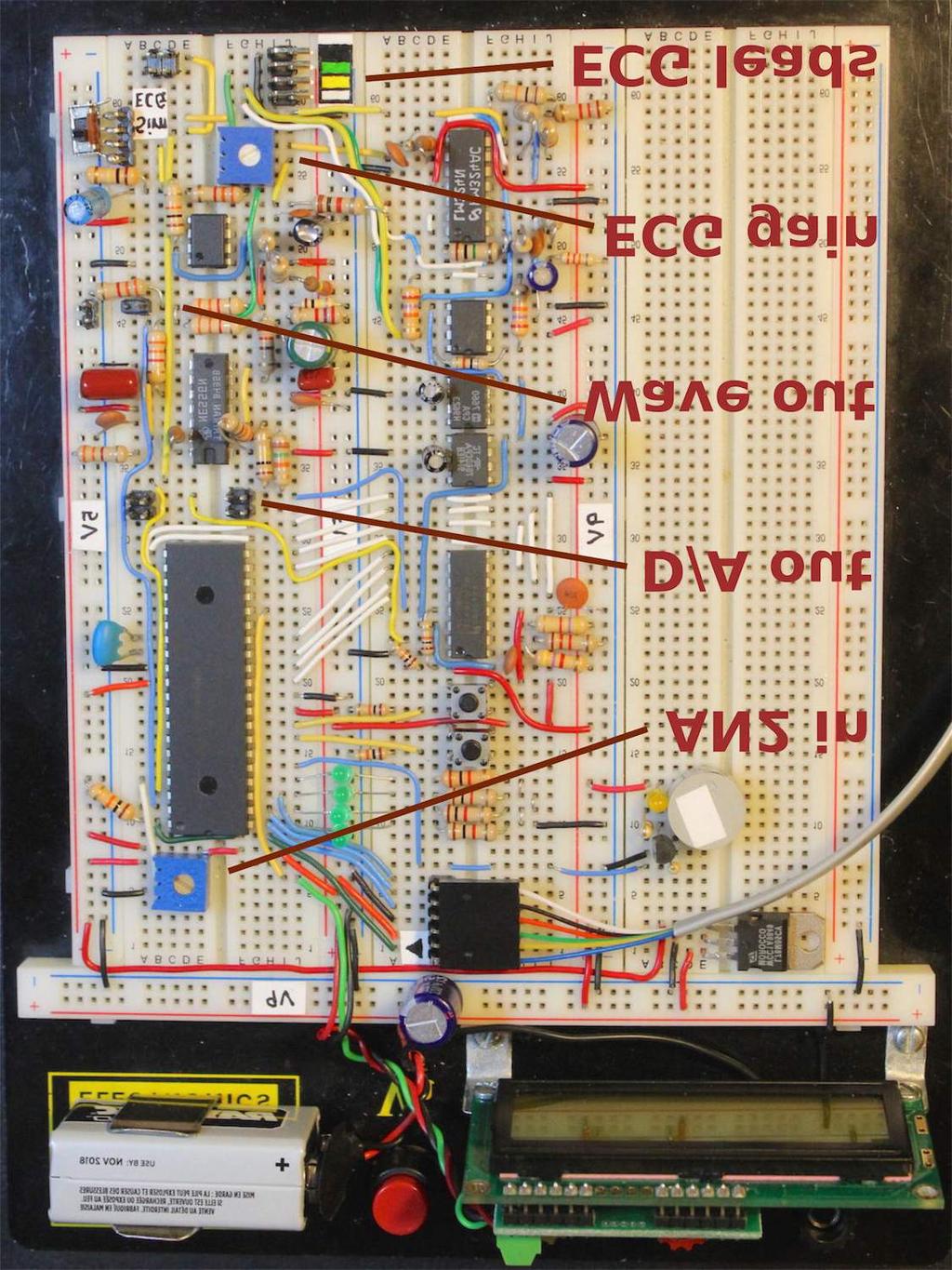
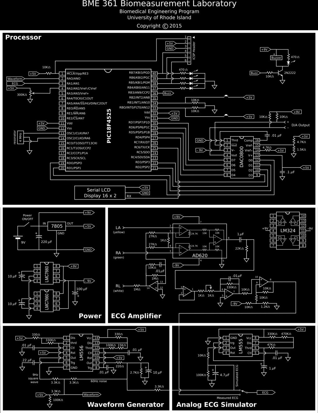
1 BME 361 Biomeasurement Laboratory Demonstration Biomedical Engineering Program University of Rhode Island June 10, 2015 The functional units on this demonstration bread board include a PIC18F4525 processor, a D/A converter, an LCD display, a waveform/noise generator, an analog ECG simulator, and an ECG amplifier. The system is programmed with the MPLab IDE v8.89 via the ICD 3 programmer. The schematics, bill of materials, and C source code are attached in the end. The breadboard is shown below with the ICD 3 programmer connected. The ECG leads are also shown. The picture on the next page shows the connectors for attaching two oscilloscope probes (D/A out and Wave out), the potentiometer for adjusting the inout voltage to A/D channel AN2, the potentiometer for adjusting the ECG gain, and the connector for attaching the ECG leads. Copyright 2015 BME, University of Rhode Island
2

, compared to a real ECG waveform recorded from a human subject on channel 1 (orange).")
3 The system has been programmed to perform the following 10 functions. Function 00 Binary counter The binary count is displayed via the 4 LED's driven by RB4-RB7. The count is also sent to the D/A converter to generate a ramp signal. The ramp can be used to verify the linearity and offset of the D/A converter. The offset can be eliminated by adjusting Vref- (pin 12) of the DAC0800. Currently this voltage is set at 1.2 V with a voltage divider circuit (1.5 KΩ and 4.7 KΩ). Function 01 ECG Simulation Digitally simulated ECG is shown on channel 2 (cyan), compared to a real ECG waveform recorded from a human subject on channel 1 (orange). The timer TMR0 is set to generate interrupts at 1KHz, which provides a temporal resolution of 1 ms for the synthetic ECG waveform. Function 02 Echo (A/D D/A) The analog signal channel 1 (orange) is from the on-board waveform generator that produces a 9-Hz square wave mixed with simulated 60 Hz noise. The analog signal is acquired by the on-chip D/A via channel AN0 (pin 2) at a sampling rate of 240 Hz and directly outputted to the D/A converter as shown on channel 2 (cyan).
 and ground to change the square wave closer to a sine wave.")

4 Function 03 fs 17 Hz The sampling rate can be adjusted via the 100 KΩ potentiometer connected to AN2 (pin 4). A 47 µf capacitor is temporarily connected between AN0 (pin 2) and ground to change the square wave closer to a sine wave. A set of sampling rates ranging from 16 Hz to 228 Hz is programmed into the processor. The purpose is to observe the the effect of sampling rate. For example, aliasing is demonstrated in the right figure with a sampling rate of 17 Hz, which is just below the Nyquest sampling rate for the 9 Hz signal. The next figure shows the result with a sampling rate of 70 Hz. Function 04 Derivative A digital differentiator is implemented according to the following backward difference: y[n] = x[n] x[n-1] The sampling rate is 240 Hz.
![Function 05 Low-pass filter An FIR low-pass filter is implemented according to the following equation: y[n] = (x[n] + 2*x[n-1] + x[n-2) / 4 The sampling rate is 240 Hz.](/docs-images/89/98549667/images/5-0.jpg "Function 06 Hi-freq enhance An FIR high-frequency enhancement filter is implemented according to the following equation: y[n] = 2*x[n] - (x[n] + 2*x[n-1] + x[n-2) / 4 The sampling rate is 240 Hz.")
5 Function 05 Low-pass filter An FIR low-pass filter is implemented according to the following equation: y[n] = (x[n] + 2*x[n-1] + x[n-2) / 4 The sampling rate is 240 Hz. Function 06 Hi-freq enhance An FIR high-frequency enhancement filter is implemented according to the following equation: y[n] = 2*x[n] - (x[n] + 2*x[n-1] + x[n-2) / 4 The sampling rate is 240 Hz. Function 07 60Hz notch filtr An FIR 60-Hz notch filter is implemented according to the following equation: y[n] = (x[n] + x[n-2) / 2 The sampling rate is 240 Hz.

 algorithm for QRS detection. The sampling rate is set at 200 Hz.")
6 Function 08 Median filter A median filter is implemented by performing a bubble sort of the present sample point and the past 8 sample points. The output is the median of the 9 points. The result in the figure shows the effect of edge-preserving smoothing of the median filter. The 60 Hz noise is eliminated, while the edges are preserved. The filter output shows a delay of 25 ms, which is longer than those of the previous filters. Function 09 HR: 74 bpm A heart meter is implemented by executing the multiplication of backward differences (MOBD) algorithm for QRS detection. The sampling rate is set at 200 Hz. Figure on the right shows the ECG signal recorded from a human subject and the nonlinear transform of the MOBD algorithm. The MOBD algorithm significantly enhances the signal-to-noise ratio readily for the threshold detection. Except for the QRS complex other components such as the P wave, the T wave, and the noise are reduced to the baseline. The next figure shows the analog simulated ECG and the MOBD nonlinear transform. The simulated ECG contains 60 Hz noise, which is effectively eliminated by the MOBD algorithm.
7
8
9 /*********************************************************************************************/ /* BME 361 Biomeasurement Lab - PIC18F4525 Demo */ /* Laboratories 1-8: A/D, D/A, LCD display, ECG simulation, filters, QRS detection */ /* Instructors: John DiCecco, Ying Sun */ /* Latest update: 6/06/2015 */ /*********************************************************************************************/ /**************************** Specify the chip that we are using *****************************/ #include <p18cxxx.h> #include <timers.h> #include <math.h> #include <stdlib.h> /************************* Configure the Microcontroller PIC18f4525 **************************/ #pragma config OSC = XT #pragma config WDT = OFF #pragma config PWRT = OFF #pragma config FCMEN = OFF #pragma config IESO = OFF #pragma config BOREN = ON #pragma config BORV = 2 #pragma config WDTPS = 128 #pragma config PBADEN = OFF #pragma config DEBUG = OFF #pragma config LVP = OFF #pragma config STVREN = OFF #define _XTAL_FREQ /******************************** Define Prototype Functions *********************************/ unsigned char ReadADC(); void rx_int (void); void _highpriorityint(void); void Backlight(unsigned char state); void SetPosition(unsigned char position); void PrintLine(rom unsigned char *string, unsigned char numchars); void PrintInt(int value, unsigned char position); void PrintNum(unsigned char value1, unsigned char position1); void SetupSerial(); void ClearScreen(); void SetupADC(unsigned char channel); void Delay_ms(unsigned int x); /************************************** Global variables *************************************/ unsigned char function, mode, update, debounce0, debounce1, LEDcount, output, counter, i, j; unsigned char data0, data1, data2, array[9], rank[9], do_median, do_mobd, refractory, display; unsigned char temp, sampling[16], TMRcntH[16], TMRcntL[16], sampling_h, sampling_l; int dummy, d0, d1, d2, mobd, threshold, rri_count, hr; unsigned char ReadADC() { /************* start A/D, read from an A/D channel *****************/ unsigned char ADC_VALUE; ADCON0bits.GO = 1; // Start the AD conversion while(!pir1bits.adif) continue; // Wait until AD conversion is complete ADC_VALUE = ADRESH; // Return the highest 8 bits of the 10-bit AD conversion return ADC_VALUE; #pragma code _highpriorityint=0x8 void rx_int (void){ /****************** Set up highpriority interrup vector ******************/ _asm goto _highpriorityint _endasm Page 1 of 8
10 #pragma interrupt _highpriorityint void _highpriorityint(void) { /********** high priority interrupt service routine ************/ checkflags: if (INTCONbits.TMR0IF == 1) { // When there is a timer0 overflow, this loop runs INTCONbits.TMR0IE = 0; // Disable TMR0 interrupt INTCONbits.TMR0IF = 0; // Reset timer 0 interrupt flag to 0 if (debounce0!= 0) debounce0--; // switch debounce delay counter for INT0 if (debounce1!= 0) debounce1--; // switch debounce delay counter for INT1 TMR0H = 0xF0; // Reload TMR0 for ms count, Sampling rate = 240 Hz TMR0L = 0x7C; // 0xFFFF-0xEFB8 = 0x1047 = 4167, adjust for delay by 68 us switch (function) { case 1: // Function 1: ECG simulation TMR0H = 0xFC; // Reload TMR0 for 1 ms count, sampling rate = 1KHz TMR0L = 0xFA; // 0xFFFF-0xFC17 = 0x3E8 = 1000,adust for delay by 227 us PORTBbits.RB4 =!PORTBbits.RB4; // Toggle RB4 (pin 37) for frequency check switch (mode) { case 0: // P wave up counter++; output++; if (counter == 30) mode++; case 1: // P wave flat counter--; if (counter == 0) mode++; case 2: // P wave down counter++; output--; if (counter == 30) mode++; case 3: // PR segment counter++; if (counter == 100) mode++; case 4: // QRS complex - Q counter++; output -= 3; if (counter == 105){ counter = 0; mode++; case 5: // QRS complex - R up counter++; output += 6; if (counter == 30) mode++; case 6: // QRS complex - R down counter++; output -= 6; if (counter == 62) mode++; case 7: // QRS complex - S counter++; output += 3; if (counter == 71) { mode++; counter = 0; case 8: // ST segment counter++; if (counter == 89){ counter = 0; mode++; case 9: // T wave up counter++; output++; if (counter == 55)mode++; case 10: // T wave flat counter++; if (counter == 110) mode++; Page 2 of 8
11 case 11: // T wave down counter++; output--; if (counter == 165) mode++; case 12: // End ECG counter--; if (counter == 0) mode++; case 13: // Reset ECG counter++; if (counter == 202){ counter = mode = 0; output = 50; PORTD = output; case 2: // Function 2: Echo data0 = ReadADC(); // Read A/D and save the present sample in data0 PORTD = data0; // Echo back PORTBbits.RB4 =!PORTBbits.RB4; // Toggle RB4 (pin 37) for frequency check case 3: // Function 3: Echo (vary rate) TMR0H = sampling_h; // Reload TMR0 high-order byte TMR0L = sampling_l; // Reload TMR0 low-order byte data0 = ReadADC(); // Read A/D and save the present sample in data0 PORTD = data0; // Echo back PORTBbits.RB4 =!PORTBbits.RB4; // Toggle RB4 (pin 37) for frequency check case 4: // Function 4: Derivative data1 = data0; // Store previous data points data0 = ReadADC(); // Read A/D and save the present sample in data0 dummy = (int)data0 - data ; // Take derivative and shift to middle PORTD = (unsigned char)dummy; // Output to D/A case 5: // Function 5: Low-pass filter data2 = data1; // Store previous data points data1 = data0; data0 = ReadADC(); // Read A/D and save the present sample in data0 dummy = ((int)data0 + data1 + data1 + data2) / 4; // smoother PORTD = (unsigned char)dummy; // Output to D/A case 6: // Function 6: High-frequency enhancement filter data2 = data1; // Store previous data points data1 = data0; data0 = ReadADC(); // Read A/D and save the present sample in data0 dummy = ((int)data0 + data1 + data1 + data2) / 4; // smoother dummy = data0 + data0 - dummy; PORTD = (unsigned char)dummy; // Output to D/A case 7: // Function 7: 60Hz notch filter data2 = data1; // Store previous data points data1 = data0; data0 = ReadADC(); // Read A/D and save the present sample in data0 dummy = ((int)data0 + data2) / 2; // 60 Hz notch PORTD = (unsigned char)dummy; // Output to D/A case 8: // Function 8: Median filter data0 = ReadADC(); // Read A/D and save the present sample in data0 do_median = 1; // Flag main() to do median filter Page 3 of 8
12 case 9: // Function 9: Heart rate meter TMR0H = 0xED; // Reload TMR0 for 5 ms count, sampling rate = 200 Hz TMR0L = 0x44; // 0xFFFF-0xED44 = 0x12BB = 4795, (205 us delay) data1 = data0; // Move old ECG sample to data1 data0 = ReadADC(); // Store new ECG sample from ADC to data0 PORTBbits.RB2 =!PORTBbits.RB2; // Toggle RB2 for sampling rate check do_mobd = 1; // Flag main() to do MOBD for QRS detection INTCONbits.TMR0IE = 1; // Enable TMR0 interrupt if (INTCONbits.INT0IF == 1) { // INT0 (pin 33) negative edge INTCONbits.INT0IE = 0; // Disable interrupt INTCONbits.INT0IF = 0; // Reset interrupt flag if (debounce0 == 0) { if (function <= 0) function = 9; // Set function range 0-9 else function--; if (function == 9) SetupADC(1); // ECG comes from AN1 channel else SetupADC(0); // Others come from AN0 channel update = 1; // Signal main() to update LCD dispaly debounce0 = 10; // Set switch debounce delay counter decremented by TMR0 INTCONbits.INT0IE = 1; // Enable interrupt goto checkflags; // Check again in case there is a timer interrupt if (INTCON3bits.INT1IF == 1) { // INT1 (pin 34) negative edge INTCON3bits.INT1IE = 0; // Disable interrupt INTCON3bits.INT1IF = 0; // Reset interrupt flag if (debounce1 == 0) { if (function >= 9) function = 0; // Set function range 0-9 else function++; if (function == 9) SetupADC(1); // ECG comes from AN1 channel else SetupADC(0); // Others come from AN0 channel update = 1; // Signal main() to update LCD dispaly debounce1 = 10; // Set switch debounce delay counter decremented by TMR0 INTCON3bits.INT1IE = 1; // Enable interrupt goto checkflags; // Check again in case there is a timer interrupt void Transmit(unsigned char value) { /********** Send an ASCII Character to USART ***********/ while(!pir1bits.txif) continue; // Wait until USART is ready TXREG = value; // Send the data while (!PIR1bits.TXIF) continue; // Wait until USART is ready Delay_ms (5); // Wait for 5 ms void ClearScreen(){ /************************** Clear LCD Screen ***************************/ Transmit(254); // See datasheets for Serial LCD and HD44780 Transmit(0x01); // Available on our course webpage void Backlight(unsigned char state){ /************* Turn LCD Backlight on/off ***************/ Transmit(124); if (state) Transmit(0x9D); // If state == 1, backlight on else Transmit(0x81); // otherwise, backlight off void SetPosition(unsigned char position){ /********** Set LCD Cursor Position *************/ Transmit(254); Page 4 of 8
13 Transmit(128 + position); void PrintLine(rom unsigned char *string, unsigned char numchars){ /**** Print characters ****/ unsigned char count; for (count=0; count<numchars; count++) Transmit(string[count]); void PrintInt(int value, unsigned char position){ /******** Print number at position *********/ int units, tens, hundreds, thousands; SetPosition(position); // Set at the present position if (value > 9999) { PrintLine((rom unsigned char*)"over", 4); return; if (value < -9999) { PrintLine((rom unsigned char*)"under", 5); return; if (value < 0) { value = -value; Transmit(45); else Transmit(43); thousands = value / 1000; // Get the thousands digit, convert to ASCII and send if (thousands!= 0) Transmit(thousands + 48); value = value - thousands * 1000; hundreds = value / 100; // Get the hundreds digit, convert to ASCII and send Transmit(hundreds + 48); value = value - hundreds * 100; tens = value / 10; // Get the tens digit, convert to ASCII and send Transmit(tens + 48); units = value - tens * 10; Transmit(units + 48); // Convert to ASCII and send void PrintNum(unsigned char value1, unsigned char position1){ /** Print number at position ***/ int units, tens, hundreds, thousands; SetPosition(position1); // Set at the present position hundreds = value1 / 100; // Get the hundreds digit, convert to ASCII and send if (hundreds!= 0) Transmit(hundreds + 48); else Transmit(20); value1 = value1 - hundreds * 100; tens = value1 / 10; // Get the tens digit, convert to ASCII and send Transmit(tens + 48); units = value1 - tens * 10; Transmit(units + 48); // Convert to ASCII and send void SetupSerial(){ /*********** Set up the USART Asynchronous Transmit (pin 25) ************/ TRISC = 0x80; // Transmit and receive, 0xC0 if transmit only SPBRG = 25; // 9600 BAUD at 4MHz: 4,000,000/(16x9600) - 1 = TXSTAbits.TXEN = 1; // Transmit enable TXSTAbits.SYNC = 0; // Asynchronous mode RCSTAbits.CREN = 1; // Continuous receive (receiver enabled) RCSTAbits.SPEN = 1; // Serial Port Enable TXSTAbits.BRGH = 1; // High speed baud rate void SetupADC(unsigned char channel){ /******** Configure A/D and Set the Channel **********/ TRISA = 0b ; // Set all of Port A as input Page 5 of 8
14 // ADCON2 Setup // bit 7: Left justify result of AD (Lowest 6bits of ADRESL are 0's) (0) // bit 6: Unimplemented // bit 5-3: AD aquisition time set to 2 TAD (001) // bit 2-0: Conversion clock set to Fosc/8 (001) ADCON2 = 0b ; // ADCON1 Setup // bit 7-6: Unimplemented // bit 5: Vref - (VSS) (0) // bit 4: Vref + (VDD) (0) // bit 3-0: Configuration of AD ports (Set A0-A4, others to digital, including the PORTB) ADCON1 = 0b ; // ADCON0 Setup // bit 7,6 = Unimplemented // bits 5-2 = Channel select // bit 1: GO Bit (Starts Conversion when = 1) // bit 0: AD Power On ADCON0 = (channel << 2) + 0b ; PIE1bits.ADIE = 0; // Turn off the AD interrupt PIR1bits.ADIF = 0; // Reset the AD interrupt flag void Delay_ms(unsigned int x){ /****** Generate a delay for x ms, assuming 4 MHz clock ******/ unsigned char y; for(;x > 0; x--) for(y=0; y< 82;y++); void main(){ /****************************** Main program **********************************/ function = mode = LEDcount = counter = debounce0 = debounce1 = 0; // Initialize display = do_median = do_mobd = rri_count = 0; threshold = 50; // Threshold for the MOBD QRS-detection algorithm update = 1; // Flag to signal LCD update output = 50; // Baseline for ECG simulation sampling[0] = 16; sampling[1] = 17; sampling[2] = 18; sampling[3] = 19; sampling[4] = 20; sampling[5] = 25; sampling[6] = 30; sampling[7] = 50; sampling[8] = 70; sampling[9] = 88; sampling[10] = 108; sampling[11] = 126; sampling[12] = 145; sampling[13] = 173; sampling[14] = 192; sampling[15] = 228; TMRcntH[0] = 11; TMRcntH[1] = 26; TMRcntH[2] = 38; TMRcntH[3] = 50; TMRcntH[4] = 60; TMRcntH[5] = 99; TMRcntH[6] = 125; TMRcntH[7] = 177; TMRcntH[8] = 200; TMRcntH[9] = 212; TMRcntH[10] = 220; TMRcntH[11] = 225; TMRcntH[12] = 229; TMRcntH[13] = 234; TMRcntH[14] = 236; TMRcntH[15] = 239; TMRcntL[0] = 219; TMRcntL[1] = 55; TMRcntL[2] = 251; TMRcntL[3] = 103; TMRcntL[4] = 175; TMRcntL[5] = 191; TMRcntL[6] = 201; TMRcntL[7] = 223; TMRcntL[8] = 49; TMRcntL[9] = 151; TMRcntL[10] = 124; TMRcntL[11] = 242; TMRcntL[12] = 244; TMRcntL[13] = 75; TMRcntL[14] = 119; TMRcntL[15] = 184; sampling_h = 0xF0; // initialize for ms count, Sampling rate = 240 Hz sampling_l = 0x7C; // 0xFFFF-0xEFB8 = 0x1047 = 4167, adjust for delay by 68 us TRISB = 0b ; // RB0-1 as inputs, others outputs, RB3 drives buzzer TRISD = 0b ; // Set all port D pins as outputs PORTD = 0; // Set port D to 0's SetupADC(0); // Call SetupADC() to set up channel 0, AN0 (pin 2) SetupSerial(); // Set up USART Asynchronous Transmit for LCD display T0CON = 0b ; // Setup the timer control register for interrupt INTCON = 0b ; // GIE(7) = TMR0IE = INT0IE = 1 INTCONbits.TMR0IE = 1; // Enable TMR0 interrupt INTCON2bits.INTEDG0 = 0; // Set pin 33 (RB0/INT0) for negative edge trigger INTCON2bits.INTEDG1 = 0; // Set pin 34 (RB1/INT1) for negative edge trigger INTCONbits.INT0IE = 1; // Enable INT0 interrupt INTCON3bits.INT1IE = 1; // Enable INT1 interrupt Delay_ms(3000); // Wait until the LCD display is ready Backlight(1); // turn LCD display backlight on Page 6 of 8
15 ClearScreen(); // Clear screen and set cursor to first position PrintLine((rom unsigned char*)" BME 361 Demo", 14); SetPosition(64); // Go to beginning of Line 2; PrintLine((rom unsigned char*)" Biomeasurement",15); // Put your trademark here Delay_ms(3000); ClearScreen(); // Clear screen and set cursor to first position PrintLine((rom unsigned char*)"function", 8); while (1) { if (update) { // The update flag is set by INT0 or INT1 update = 0; // Reset update flag PrintNum(function, 8); // Update the function number on LCD display if (function!= 0) LEDcount = PORTB = 0; // Reset LED's SetPosition(64); // Go to beginning of Line 2; switch (function) { case 0: PrintLine((rom unsigned char*)"binary counter ",16); case 1: PrintLine((rom unsigned char*)"ecg simulation ",16); case 2: PrintLine((rom unsigned char*)"echo (A/D - D/A)",16); case 3: PrintLine((rom unsigned fs Hz",16); case 4: PrintLine((rom unsigned char*)"derivative ",16); case 5: PrintLine((rom unsigned char*)"low-pass filter ",16); case 6: PrintLine((rom unsigned char*)"hi-freq enhance ",16); case 7: PrintLine((rom unsigned char*)"60hz notch filtr",16); case 8: PrintLine((rom unsigned char*)"median filter ",16); case 9: PrintLine((rom unsigned char*)"hr = bpm ",16); switch (function) { case 0: // Function 0: Binary counter LEDcount++; // Upcounter PORTB = LEDcount & 0b ; // Mask out the lower 4 bits PORTD = LEDcount; // Output ramp to verify linearity of the D/A Delay_ms(10); // Delay to slow down the counting case 3: // Function 3: Echo (vary rate) INTCONbits.TMR0IE = 0; // Disable TMR0 interrupt SetupADC(2); // Switch to A/D channel AN2 counter = ReadADC(); // Read potentiometer setting from AN2 SetupADC(0); // Switch to A/D channel AN0 counter = counter >> 4; // Scale it to 0-15 temp = sampling[counter]; // Display sampling rate PrintNum(temp,74); sampling_l = TMRcntL[counter]; // Load TMR0 low-order byte sampling_h = TMRcntH[counter]; // Load TMR0 high-order byte INTCONbits.TMR0IE = 1; // Enable TMR0 interrupt Delay_ms(1000); // Delay to slow down the counting case 8: // Function 8: Median filter (9-point) if (do_median) { do_median = 0; // Reset do_median flag INTCONbits.TMR0IE = 0; // Disable TMR0 interrupt for (i=8; i>0; i--) array[i] = array[i-1]; // Store the previous 8 points array[0] = data0; // Get new data point from A/D for (i=0; i<9; i++) rank[i] = array[i]; // Make a copy of data array for (i=0; i<5; i++) { // Perform a bubble sort for (j=i+1; j<9; j++) { if (rank[i] < rank[j]) { temp = rank[i]; // Swap rank[i] = rank[j]; rank[j] = temp; Page 7 of 8
16 PORTD = rank[4]; // Median is at rank[4] of rank[0-8] INTCONbits.TMR0IE = 1; // Enable TMR0 interrupt case 9: // Function 9: Multiplication of Backward Differences (MOBD) if (do_mobd){ // MOBD = Multiplication of Backwards Differences INTCONbits.TMR0IE = 0; // Disable TMR0 interrupt do_mobd = 0; // Reset new_data flag d2 = d1; // Move oldest difference to d2 d1 = d0; // Move older difference to d1 d0 = (int)data0 - data1; // Store new difference in d0, (int) casting important rri_count++; // Increment RR-interval mobd = 0; // mobd = 0, unless sign consistency is met: if (d0 > 0 && d1 > 0 && d2 > 0){ // (1) If 3 consecutive positive differences mobd = d0 * d1; // Multiply first two differences mobd = mobd >> 3; // Scale down (divide by 8) mobd = mobd * d2; // Multiply the oldest difference if (d0 < 0 && d1 < 0 && d2 < 0){ // (2) If 3 consecutive negative differences d0 = -d0; // Take absolute value of differences d1 = -d1; d2 = -d2; mobd = d0 * d1; // Multiply first two differences mobd = mobd >> 3; // Scale down (divide by 8) mobd = mobd * d2; // Multiply the oldest difference if (refractory){ // Avoid detecting extraneous peaks after QRS refractory++; if (refractory == 40){ // Delay for 200 ms refractory = 0; // Reset refractory flag to 0 PORTBbits.RB3 = 0; // Turn buzzer/led off (Pin 36) else if (mobd > threshold){ // If a peak is detected, refractory = 1; // Set refractory flag PORTBbits.RB3 = 1; // Turn buzzer/led on (Pin 36) display = 1; // Set display flag PORTD =(unsigned char)mobd; // Output mobd value to Port D INTCONbits.TMR0IE = 1; // Enable TMR0 interrupt if (display){ // Display Heart Rate in 3 digits hr = 12000/rri_count; // 60/0.005 = rri_count = 0; // Reset RRI counter PrintNum(hr, 71); // Isolates each digit and displays display = 0; // Reset display flag Page 8 of 8
unsigned char ReadADC() { /************* start A/D, read from an A/D channel *****************/ unsigned char ADC_VALUE;
 { /************* start A/D, read from an A/D channel *****************/ unsigned char ADC_VALUE;") /*********************************************************************************************/ /* BME 361 Biomeasurement Lab - PIC18F4525BT Demo */ /* Laboratories 1-8: A/D, D/A, LCD display, ECG simulation,
/*********************************************************************************************/ /* BME 361 Biomeasurement Lab - PIC18F4525BT Demo */ /* Laboratories 1-8: A/D, D/A, LCD display, ECG simulation,
Electromyogram Based Controls Acting on Lego Mindstorm Car
 BME 484 - Capstone Design Department of Electrical, Computer and Biomedical Engineering University of Rhode Island, Kingston, RI 02881 Electromyogram Based Controls Acting on Lego Mindstorm Car Design
Embedded systems. Exercise session 3. Microcontroller Programming Lab Preparation
 Embedded systems Exercise session 3 Microcontroller Programming Lab Preparation Communications Contact Mail : michael.fonder@ulg.ac.be Office : 1.82a, Montefiore Website for the exercise sessions and the
C:\Users\cunningh\StaysOnPC\ME430 Downloads & Projects\exam2_problem1\problem1Cunningham.c
 C:\Users\cunningh\StaysOnPC\ME430 Downloads & Projects\exam2_problem1\problem1Cunningham.c / FileName: problem1cunningham.c Processor: PIC18F4520 Compiler: MPLAB C18 v.3.06 This file does the following...
Speed Control of a DC Motor using Digital Control
 Speed Control of a DC Motor using Digital Control The scope of this project is threefold. The first part of the project is to control an LCD display and use it as part of a digital tachometer. Secondly,
Timer0..Timer3. Interrupt Description Input Conditions Enable Flag
 Timer0..Timer3 Timers are pretty useful: likewise, Microchip provides four different timers for you to use. Like all interrupts, you have to Enable the interrupt, Set the conditions of the interrupt, and
Interrupts on PIC18F252 Part 2
 Interrupts on PIC18F252 Part 2 Following pages list Special Function Registers (SFRs) involved in interrupt configuration and operation on PIC18F252 microcontroller. (Copied from Microchip s PIC18Fxx2
Human Response Timer
 Human Response Timer Matthew Beckler beck0778@umn.edu EE2361 Lab Section 007 March 29, 2006 Abstract In this lab, we create a very useful application, a human response timer. The user s reaction time is
/*Algorithm: This code display a centrifuge with five variable speed RPM by increaseing */
 /*Algorithm: This code display a centrifuge with five variable speed RPM by increaseing */ /*the speed the cell which are less dense can float and the cell that are denser can sink*/ /*the user has five
Accurate Time and Interrupts
 Accurate Time and Interrupts Matthew Beckler beck0778@umn.edu EE2361 Lab Section 007 March 7, 2006 Abstract In this lab, we create a very accurate digital clock using one of the microcontroller s timers.
Laboratory Exercise 5 - Analog to Digital Conversion
 Laboratory Exercise 5 - Analog to Digital Conversion The purpose of this lab is to control the blinking speed of an LED through the Analog to Digital Conversion (ADC) module on PIC16 by varying the input
The University of Texas at Arlington Lecture 21_Review
 The University of Texas at Arlington Lecture 21_Review CSE 5442/3442 Agenda Tuesday December 1st Hand back Homework 7,8 and 9. Go over questions and answers Exam 3 Review Note: There will be a take home
Embedded Systems Programming and Architectures
 Embedded Systems Programming and Architectures Lecture No 10 : Data acquisition and data transfer Dr John Kalomiros Assis. Professor Department of Post Graduate studies in Communications and Informatics
Remote Controlled KitchenAid Mixer for the Clients at ADEC. Appendices. Arnaud Bacye Karina Dubé Justin Erman Matthew Martin
 Mix Masters Remote Controlled KitchenAid Mixer for the Clients at ADEC Appendices Arnaud Bacye Karina Dubé Justin Erman Matthew Martin Table of Contents A Hardware Schematics and Boards 2 A.1 Current Schematics
Interrupts on PIC18F252 Part 2. Interrupts Programming in C Language
 Interrupts on PIC18F252 Part 2 Interrupts Programming in C Language Programming interrupts in C language using XC8 compiler is significantly simplified compared to C18 compiler. This note explains the
Analog Output with a Digital to Analog Converter
 Analog Output with a Digital to Analog Converter Matthew Beckler beck0778@umn.edu EE2361 Lab 007 April 5, 2006 Abstract Without help, microcontrollers can have great trouble creating analog signals. Approximations
1 Introduction to Computers and Computer Terminology Programs Memory Processor Data Sheet Example Application...
 Overview of the PIC 16F648A Processor: Part 1 EE 361L Lab 2.1 Last update: August 19, 2011 Abstract: This report is the first of a three part series that discusses the features of the PIC 16F684A processor,
EEE394 Microprocessor and Microcontroller Laboratory Lab #6
 Exp. No #6 Date: INTERRUPTS AND ADC IN PIC MICROCONTROLLER OBJECTIVE The purpose of the experiment is to configure external interrupt and the ADC in PIC microcontrollers. (i) To flip the LED connected
LCD. Configuration and Programming
 LCD Configuration and Programming Interfacing and Programming with Input/Output Device: LCD LCD (liquid crystal display) is specifically manufactured to be used with microcontrollers, which means that
Embedded Systems Module. 6EJ505. C Tutorial 3: using the ICD3 rev tjw
 Embedded Systems Module. 6EJ505 C Tutorial 3: using the ICD3 rev. 27.9.16 tjw Images are reproduced from Reference 1. Microchip permits the use of its images for educational purposes. Main Learning Points
Outlines. PIC Programming in C and Assembly. Krerk Piromsopa, Ph.D. Department of Computer Engineering Chulalongkorn University
 PIC ming in C and Assembly Outlines Microprocessor vs. MicroController PIC in depth PIC ming Assembly ming Krerk Piromsopa, Ph.D. Department of Computer Engineering Chulalongkorn University Embedded C
Capture Mode of Pic18F252
 Capture Mode of Pic18F252 PIC18F253 has two Capture/Compare/Pulse Width Modulation modules. Some devices such as ADCs, Sensors (position, velocity, accelearstion, temperature [MAX6577 converts the ambient
MicroToys Guide: PS/2 Mouse N. Pinckney April 2005
 Introduction A computer mouse provides an excellent device to acquire 2D coordinate-based user input, since most users are already familiar with it. Most mice usually come with two or three buttons, though
Interfacing PIC Microcontrollers. ADC8BIT2 Schematic. This application demonstrates analogue input sampling
 Interfacing PIC Microcontrollers ADC8BIT2 Schematic This application demonstrates analogue input sampling A manually adjusted test voltage 0-5V is provided at AN0 input A reference voltage of 2.56V is
1 Introduction to Computers and Computer Terminology Programs Memory Processor Data Sheet... 4
 Overview of the PIC 16F648A Processor: Part 1 EE 361L Lab 2.1 Last update: August 1, 2016 Abstract: This report is the first of a three part series that discusses the features of the PIC 16F648A processor,
Timer1 Capture Mode:
 Timer1 Capture Mode: Interrupt Description Input Conditions Enable Flag Timer 1 Trigger after N events N = 1.. 2 19 100ns to 0.52 sec RC0 TMR1CS = 1 TMR1IF Timer 1 Capture Mode 1 Timer 1 Capture Mode 2
C and Embedded Systems. So Why Learn Assembly Language? C Compilation. PICC Lite C Compiler. PICC Lite C Optimization Results (Lab #13)
") C and Embedded Systems A µp-based system used in a device (i.e, a car engine) performing control and monitoring functions is referred to as an embedded system. The embedded system is invisible to the user
C and Embedded Systems A µp-based system used in a device (i.e, a car engine) performing control and monitoring functions is referred to as an embedded system. The embedded system is invisible to the user
BME 4900 Page 1 of 2. Meeting 2: Personal Progress Report 12/2/09 Team 12 with Drew Seils. Semester One Week Two
 BME 4900 Page 1 of 2 Semester One Week Two These past two saw a lot of progress with the Revo stationary bike project. During Thanksgiving break Shane spent most of his time doing research for the power
ELCT 912: Advanced Embedded Systems
 ELCT 912: Advanced Embedded Systems Lecture 10: Applications for Programming PIC18 in C Dr. Mohamed Abd El Ghany, Department of Electronics and Electrical Engineering Programming the PIC18 to transfer
ECE Homework #10
 Timer 0/1/2/3 ECE 376 - Homework #10 Timer 0/1/2/3, INT Interrupts. Due Wednesday, November 14th, 2018 1) Write a program which uses INT and Timer 0/1/2/3 interrupts to play the cord C#major for 1.000
EE6008-Microcontroller Based System Design Department Of EEE/ DCE
 UNIT- II INTERRUPTS AND TIMERS PART A 1. What are the interrupts available in PIC? (Jan 14) Interrupt Source Enabled by Completion Status External interrupt from INT INTE = 1 INTF = 1 TMR0 interrupt T0IE
Laboratory 10. Programming a PIC Microcontroller - Part II
 Laboratory 10 Programming a PIC Microcontroller - Part II Required Components: 1 PIC16F88 18P-DIP microcontroller 1 0.1 F capacitor 3 SPST microswitches or NO buttons 4 1k resistors 1 MAN 6910 or LTD-482EC
Dept. of Computer Engineering Final Exam, First Semester: 2016/2017
 Philadelphia University Faculty of Engineering Course Title: Embedded Systems (630414) Instructor: Eng. Anis Nazer Dept. of Computer Engineering Final Exam, First Semester: 2016/2017 Student Name: Student
EET203 MICROCONTROLLER SYSTEMS DESIGN Serial Port Interfacing
 EET203 MICROCONTROLLER SYSTEMS DESIGN Serial Port Interfacing Objectives Explain serial communication protocol Describe data transfer rate and bps rate Describe the main registers used by serial communication
Using Timers of Microchip PIC18F Microcontrollers
 Using Timers of Microchip PIC18F Microcontrollers ARSLAB - Autonomous and Robotic Systems Laboratory Dipartimento di Matematica e Informatica - Università di Catania, Italy santoro@dmi.unict.it L.A.P.
2. (2 pts) If an external clock is used, which pin of the 8051 should it be connected to?
 If an external clock is used, which pin of the 8051 should it be connected to?") ECE3710 Exam 2. Name _ Spring 2013. 5 pages. 102 points, but scored out of 100. You may use any non-living resource to complete this exam. Any hint of cheating will result in a 0. Part 1 Short Answer 1.
ECE3710 Exam 2. Name _ Spring 2013. 5 pages. 102 points, but scored out of 100. You may use any non-living resource to complete this exam. Any hint of cheating will result in a 0. Part 1 Short Answer 1.
ME 6405 Introduction to Mechatronics
 ME 6405 Introduction to Mechatronics Fall 2006 Instructor: Professor Charles Ume Microchip PIC Manufacturer Information: Company: Website: http://www.microchip.com Reasons for success: Became the hobbyist's
Hong Kong Institute of Vocational Education Digital Electronics & Microcontroller. 8. Microcontroller
 8. Microcontroller Textbook Programming Robot Controllers, Myke Predko, McGraw Hill. Reference PIC Robotics: A Beginner's Guide to Robotics Projects Using the PIC Micro, John Iovine, McGraw Hill. Embedded
LABORATORY MANUAL Interfacing LCD 16x2, Keypad 4x4 and 7Segment Display to PIC18F4580
 LABORATORY MANUAL Interfacing LCD 16x2, Keypad 4x4 and 7Segment Display to PIC18F458 1. OBJECTIVES: 1.1 To learn how to interface LCD 16x2, Keypad 4x4 and 7Segment Display to the microcontroller. 1.2 To
Introduction to Microcontroller Apps for Amateur Radio Projects Using the HamStack Platform.
 Introduction to Microcontroller Apps for Amateur Radio Projects Using the HamStack Platform www.sierraradio.net www.hamstack.com Topics Introduction Hardware options Software development HamStack project
UNIVERSITY OF BOLTON SCHOOL OF ENGINEERING MSC SYSTEMS ENGINEERING AND ENGINEERING MANAGEMENT SEMESTER 2 EXAMINATION 2016/2017
 TW30 UNIVERSITY OF BOLTON SCHOOL OF ENGINEERING MSC SYSTEMS ENGINEERING AND ENGINEERING MANAGEMENT SEMESTER 2 EXAMINATION 2016/2017 MICROPROCESSOR BASED SYSTEMS MODULE NO: EEM7016 Date: Wednesday 17 May
EE 361L Digital Systems and Computer Design Laboratory
 EE 361L Digital Systems and Computer Design Laboratory University of Hawaii Department of Electrical Engineering by Galen Sasaki and Ashok Balusubramaniam Quick Overview of PIC16F8X Version 1.0 Date: 9/4/01
Team 8: Robert Blake Craig Goliber Alanna Ocampo
 Team 8: Robert Blake Craig Goliber Alanna Ocampo Objective of the design CAD Presentation Microcontroller Implementation PCB Design Design Limitations Conclusion Problem: Design a centrifuge which was
Lecture (09) PIC16F84A LCD interface LCD. Dr. Ahmed M. ElShafee
 PIC16F84A LCD interface LCD. Dr. Ahmed M. ElShafee") Lecture (09) PIC16F84A LCD interface PIC16F84A LCD interface Assignment 01, 4 Zones fire controller board Assignment 02, automatic water tank controller Dr. Ahmed M. ElShafee ١ ٢ LCD LCD (Liquid Crystal
Lecture (09) PIC16F84A LCD interface PIC16F84A LCD interface Assignment 01, 4 Zones fire controller board Assignment 02, automatic water tank controller Dr. Ahmed M. ElShafee ١ ٢ LCD LCD (Liquid Crystal
Chapter 11: Interrupt On Change
 Chapter 11: Interrupt On Change The last two chapters included examples that used the external interrupt on Port C, pin 1 to determine when a button had been pressed. This approach works very well on most
MPLAB SIM. MPLAB IDE Software Simulation Engine Microchip Technology Incorporated MPLAB SIM Software Simulation Engine
 MPLAB SIM MPLAB IDE Software Simulation Engine 2004 Microchip Technology Incorporated MPLAB SIM Software Simulation Engine Slide 1 Welcome to this web seminar on MPLAB SIM, the software simulator that
The Freescale MC908JL16 Microcontroller
 Ming Hsieh Department of Electrical Engineering EE 459Lx - Embedded Systems Design Laboratory The Freescale MC908JL16 Microcontroller by Allan G. Weber 1 Introduction The Freescale MC908JL16 (also called
More Fun with Timer Interrupts
 More Fun with Timer Interrupts Chords Objective: Play a musical chord each time you press a button: Button RC0 RC1 RC2 Timer Timer0 Timer1 Timer3 RB0 A3 C4 E4 RB1 B3 D4 F4 RB2 C4 E4 G4 Calculations: Assume
3. (a) Explain the steps involved in the Interfacing of an I/O device (b) Explain various methods of interfacing of I/O devices.
 Explain the steps involved in the Interfacing of an I/O device (b) Explain various methods of interfacing of I/O devices.") Code No: R05320202 Set No. 1 1. (a) Discuss the minimum mode memory control signals of 8086? (b) Explain the write cycle operation of the microprocessor with a neat timing diagram in maximum mode. [8+8]
Code No: R05320202 Set No. 1 1. (a) Discuss the minimum mode memory control signals of 8086? (b) Explain the write cycle operation of the microprocessor with a neat timing diagram in maximum mode. [8+8]
SANKALCHAND PATEL COLLEGE OF ENGINEERING, VISNAGAR. ELECTRONICS & COMMUNICATION DEPARTMENT Question Bank- 1
 SANKALCHAND PATEL COLLEGE OF ENGINEERING, VISNAGAR ELECTRONICS & COMMUNICATION DEPARTMENT Question Bank- 1 Subject: Microcontroller and Interfacing (151001) Class: B.E.Sem V (EC-I & II) Q-1 Explain RISC
Timer2 Interrupts. NDSU Timer2 Interrupts September 20, Background:
 Background: Timer2 Interrupts The execution time for routines sometimes needs to be set. This chapter loops at several ways to set the sampling rate. Example: Write a routine which increments an 8-bit
DPScope SE Programming Interface Description
 DPScope SE Programming Interface Description Version 1.0.0 July 24, 2012 1 Introduction The DPScope SE is acting as a standard USB HID (Human Interface device). Key connection parameters are: Vendor ID
University of Jordan Faculty of Engineering and Technology Department of Computer Engineering Embedded Systems Laboratory
 University of Jordan Faculty of Engineering and Technology Department of Computer Engineering Embedded Systems Laboratory 0907334 6 Experiment 6:Timers Objectives To become familiar with hardware timing
By the end of Class. Outline. Homework 5. C8051F020 Block Diagram (pg 18) Pseudo-code for Lab 1-2 due as part of prelab
 Pseudo-code for Lab 1-2 due as part of prelab") By the end of Class Pseudo-code for Lab 1-2 due as part of prelab Homework #5 on website due before next class Outline Introduce Lab 1-2 Counting Timers on C8051 Interrupts Laboratory Worksheet #05 Copy
By the end of Class Pseudo-code for Lab 1-2 due as part of prelab Homework #5 on website due before next class Outline Introduce Lab 1-2 Counting Timers on C8051 Interrupts Laboratory Worksheet #05 Copy
ALFRED MAZHINDU
 SENSORS AND ACTUATORS LAB_2 ALFRED MAZHINDU 09022270 DATA ACQUISITION FROM AN OPTICAL SENSOR LABORATORY STAGE 2_10/11 Contents Table of Figures... 2 Lab: Data acquisition from an optical sensor... 3 Introduction...
16.317: Microprocessor Systems Design I Fall Exam 3 December 15, Name: ID #:
 16.317: Microprocessor Systems Design I Fall 2014 Exam 3 December 15, 2014 Name: ID #: For this exam, you may use a calculator and one 8.5 x 11 double-sided page of notes. All other electronic devices
8051 Peripherals. On-Chip Memory Timers Serial Port Interrupts. Computer Engineering Timers
 8051 Peripherals On-Chip Memory Timers Serial Port Interrupts Computer Engineering 2 2-1 8051 Timers 8051 Timers The 8051 has 2 internal 16-bit timers named Timer 0 and Timer 1 Each timer is a 16-bit counter
UNIVERSITY OF BOLTON SCHOOL OF ENGINEERING B.ENG (HONS) ELECTRICAL AND ELECTRONIC ENGINEERING EXAMINATION SEMESTER /2016
 ELECTRICAL AND ELECTRONIC ENGINEERING EXAMINATION SEMESTER /2016") UNIVERSITY OF BOLTON TW59 SCHOOL OF ENGINEERING B.ENG (HONS) ELECTRICAL AND ELECTRONIC ENGINEERING EXAMINATION SEMESTER 1-2015/2016 INTERMEDIATE EMBEDDED SYSTEMS MODULE NO: EEE5004 Date: Thursday 14 January
UNIVERSITY OF BOLTON TW59 SCHOOL OF ENGINEERING B.ENG (HONS) ELECTRICAL AND ELECTRONIC ENGINEERING EXAMINATION SEMESTER 1-2015/2016 INTERMEDIATE EMBEDDED SYSTEMS MODULE NO: EEE5004 Date: Thursday 14 January
Microcontroller Overview
 Microcontroller Overview Microprocessors/Microcontrollers/DSP Microcontroller components Bus Memory CPU Peripherals Programming Microcontrollers vs. µproc. and DSP Microprocessors High-speed information
Implementation of Temperature Sensor on PICM4520 Microcontroller
 Implementation of Temperature Sensor on PICM4520 Microcontroller Application Note Brad Pasbjerg Design Team 7 March 30 th, 2012 1 Table of Contents Cover... 1 Table of Contents... 2 Abstract... 3 Keywords...
PIC Microcontroller Introduction
 PIC Microcontroller Introduction The real name of this microcontroller is PICmicro (Peripheral Interface Controller), but it is better known as PIC. Its first ancestor was designed in 1975 by General Instruments.
UNIVERSITY OF BOLTON SCHOOL OF ENGINEERING. BEng(Hons) Electrical and Electronics Engineering SEMESTER 1 EXAMINATION 2016/2017
 Electrical and Electronics Engineering SEMESTER 1 EXAMINATION 2016/2017") TW34 UNIVERSITY OF BOLTON SCHOOL OF ENGINEERING BEng(Hons) Electrical and Electronics Engineering SEMESTER 1 EXAMINATION 2016/2017 INTERMEDIATE EMBEDDED SYSTEMS MODULE NO: EEE5004 Date: Thursday 12 January
TW34 UNIVERSITY OF BOLTON SCHOOL OF ENGINEERING BEng(Hons) Electrical and Electronics Engineering SEMESTER 1 EXAMINATION 2016/2017 INTERMEDIATE EMBEDDED SYSTEMS MODULE NO: EEE5004 Date: Thursday 12 January
Lab 5: LCD and A/D: Digital Voltmeter
 Page 1/5 OBJECTIVES Learn how to use C (as an alternative to Assembly) in your programs. Learn how to control and interface an LCD panel to a microprocessor. Learn how to use analog-to-digital conversion
University Program Advance Material
 University Program Advance Material Advance Material Modules Introduction ti to C8051F360 Analog Performance Measurement (ADC and DAC) Detailed overview of system variances, parameters (offset, gain, linearity)
Embedded System Design
 ĐẠI HỌC QUỐC GIA TP.HỒ CHÍ MINH TRƯỜNG ĐẠI HỌC BÁCH KHOA KHOA ĐIỆN-ĐIỆN TỬ BỘ MÔN KỸ THUẬT ĐIỆN TỬ Embedded System Design : Microcontroller 1. Introduction to PIC microcontroller 2. PIC16F84 3. PIC16F877
ECG (EKG) Primer Jingxi Zhang ABSTRACT
 Primer Jingxi Zhang ABSTRACT") ECG (EKG) Primer Jingxi Zhang ABSTRACT This project is for detecting human ECG (Electrocardiogram, or EKG). A tiny amplifier is embedded (
ECG (EKG) Primer Jingxi Zhang ABSTRACT This project is for detecting human ECG (Electrocardiogram, or EKG). A tiny amplifier is embedded (
MSI-P450 USER MANUAL
 MSI-P450 ANALOG INPUT/OUTPUT CARD USER MANUAL PC/104 Embedded Industrial Analog I/O Series Microcomputer Systems, Inc. 1814 Ryder Drive Baton Rouge, LA 70808 Ph (504)769-2154 Fax (504) 769-2155 Email:
8051 Training Kit Lab Book
 8051 Training Kit Lab Book Date: 25 September 2009 Document Revision: 1.05 BiPOM Electronics 16301 Blue Ridge Road, Missouri City, Texas 77489 Telephone: (713) 283-9970 Fax: (281) 416-2806 E-mail: info@bipom.com
Embedded Systems. PIC16F84A Internal Architecture. Eng. Anis Nazer First Semester
 Embedded Systems PIC16F84A Internal Architecture Eng. Anis Nazer First Semester 2017-2018 Review Computer system basic components? CPU? Memory? I/O? buses? Instruction? Program? Instruction set? CISC,
CENG-336 Introduction to Embedded Systems Development. Timers
 CENG-336 Introduction to Embedded Systems Development Timers Definitions A counter counts (possibly asynchronous) input pulses from an external signal A timer counts pulses of a fixed, known frequency
Section 13. Timer0 HIGHLIGHTS. Timer0. This section of the manual contains the following major topics:
 Section 13. Timer0 HIGHLIGHTS This section of the manual contains the following major topics: 13.1 Introduction... 13-2 13.2 Control Register... 13-3 13.3 Operation... 13-4 13.4 Timer0 Interrupt... 13-5
PIC32MX150F128 Breakout Board
 PIC32MX150F128 Breakout Board This is a description of a 32 Bit PIC32MX breakout board to be used for fast prototyping. It could also be used for conventional circuit boards to avoid the fine pitch of
Chapter 9. Input/Output (I/O) Ports and Interfacing. Updated: 3/13/12
 Ports and Interfacing. Updated: 3/13/12") Chapter 9 Input/Output (I/O) Ports and Interfacing Updated: 3/13/12 Basic Concepts in I/O Interfacing and PIC18 I/O Ports (1 of 2) I/O devices (or peripherals) such as LEDs and keyboards are essential
Chapter 9 Input/Output (I/O) Ports and Interfacing Updated: 3/13/12 Basic Concepts in I/O Interfacing and PIC18 I/O Ports (1 of 2) I/O devices (or peripherals) such as LEDs and keyboards are essential
Lecture (03) PIC16F84 (2)
 PIC16F84 (2)") Lecture (03) PIC16F84 (2) By: Dr. Ahmed ElShafee ١ PIC16F84 has a RISC architecture, or Harvard architecture in another word ٢ PIC16F84 belongs to a class of 8 bit microcontrollers of RISC architecture.
Lecture (03) PIC16F84 (2) By: Dr. Ahmed ElShafee ١ PIC16F84 has a RISC architecture, or Harvard architecture in another word ٢ PIC16F84 belongs to a class of 8 bit microcontrollers of RISC architecture.
MEMO TO: ECE 4175 students February 8, 2008 FROM: SUBJECT: First quiz on Wednesday, February 13 Open book, open notes.
 MEMO TO: ECE 4175 students February 8, 2008 FROM: John Peatman th SUBJECT: First quiz on Wednesday, February 13 Open book, open notes. Cody Planteen, Andrew Ray, and Bren Whitfield will hold a review session
UNIVERSITY OF CALIFORNIA, SANTA CRUZ BOARD OF STUDIES IN COMPUTER ENGINEERING CMPE13/L: INTRODUCTION TO PROGRAMMING IN C SPRING 2013
 Introduction Reading Concepts UNIVERSITY OF CALIFORNIA, SANTA CRUZ BOARD OF STUDIES IN COMPUTER ENGINEERING CMPE13/L: INTRODUCTION TO PROGRAMMING IN C SPRING 2013 Lab 2 Bouncing LEDs In this lab, you will
Department of Electronics and Instrumentation Engineering Question Bank
 www.examquestionpaper.in Department of Electronics and Instrumentation Engineering Question Bank SUBJECT CODE / NAME: ET7102 / MICROCONTROLLER BASED SYSTEM DESIGN BRANCH : M.E. (C&I) YEAR / SEM : I / I
MICROPROCESSORS A (17.383) Fall Lecture Outline
 Fall Lecture Outline") MICROPROCESSORS A (17.383) Fall 2010 Lecture Outline Class # 08 November 02, 2010 Dohn Bowden 1 Today s Lecture Syllabus review Programming/Software Useful information Lab Discussion on your progress/techniques
MICROPROCESSORS A (17.383) Fall 2010 Lecture Outline Class # 08 November 02, 2010 Dohn Bowden 1 Today s Lecture Syllabus review Programming/Software Useful information Lab Discussion on your progress/techniques
Table of Contents COMPANY PROFILE 1-1 SECTION 1. INTRODUCTION 1-1
 COMPANY PROFILE 1-1 SECTION 1. INTRODUCTION 1-1 Introduction... 1-2 Manual Objective... 1-3 Device Structure... 1-4 Development Support... 1-6 Device Varieties... 1-7 Style and Symbol Conventions... 1-12
Laboratory 9. Programming a PIC Microcontroller - Part I
 Laboratory 9 Programming a PIC Microcontroller - Part I Required Components: 1 PIC16F84 (4MHz) or PIC16F84A (20MHz) or compatible (e.g., PIC16F88) microcontroller 1 4MHz microprocessor crystal (20 pf),
Week1. EEE305 Microcontroller Key Points
 Week1 Harvard Architecture Fig. 3.2 Separate Program store and Data (File) stores with separate Data and Address buses. Program store Has a 14-bit Data bus and 13-bit Address bus. Thus up to 2 13 (8K)
Application Note One Wire Digital Output. 1 Introduction. 2 Electrical Parameters for One Wire Interface. 3 Start and Data Transmission
 Application Note One Wire Digital Output 1 Introduction The pressure transmitter automatically outputs pressure data, and when appropriate temperature data, in a fixed interval. The host simply waits for
OSC Ring Type Ring or Resonator type (optional) RESET Pin No Yes
 RESET Pin No Yes") General Description Features est Series is a series of 3 to 340 seconds single chip high quality voice synthesizer IC which contains one 4-bit Input port (provided for est005 and above); three 4-bit I/O
General Description Features est Series is a series of 3 to 340 seconds single chip high quality voice synthesizer IC which contains one 4-bit Input port (provided for est005 and above); three 4-bit I/O
Chapter 13. PIC Family Microcontroller
 Chapter 13 PIC Family Microcontroller Lesson 06 Special Function Registers for Control and status registers for the peripherals, input/output and Interrupt SFRs SFRs at the addresses of internal RAM/register
Analog Conversion and MAC. Student's name & ID (1): Partner's name & ID (2): Your Section number & TA's name
: Partner's name & ID (2): Your Section number & TA's name") MPS ADC Lab Exercise Analog Conversion and MAC Student's name & ID (1): Partner's name & ID (2): Your Section number & TA's name Notes: You must work on this assignment with your partner. Hand in a printed
MPS ADC Lab Exercise Analog Conversion and MAC Student's name & ID (1): Partner's name & ID (2): Your Section number & TA's name Notes: You must work on this assignment with your partner. Hand in a printed
Microcontroller & Interfacing
 Course Title Course Code Microcontroller & Interfacing EC406 Lecture : 3 Course Credit Practical : 1 Tutorial : 0 Total : 4 Course Objective At the end of the course the students will be able to Understand
DEV-1 HamStack Development Board
 Sierra Radio Systems DEV-1 HamStack Development Board Reference Manual Version 1.0 Contents Introduction Hardware Compiler overview Program structure Code examples Sample projects For more information,
MTRX3700 Mechatronics
 MTRX3700 Mechatronics 3 2015 PIC18F452 Software Exercises David Rye You are to work in a group of two students to write, debug and demonstrate a series of small assembly language and C programs that meet
Lab 5: LCD and A/D: Digital Voltmeter
 Page 1/5 OBJECTIVES Learn how to use C (as an alternative to Assembly) in your programs. Learn how to control and interface an LCD panel to a microprocessor. Learn how to use analog-to-digital conversion
The Atmel ATmega328P Microcontroller
 Ming Hsieh Department of Electrical Engineering EE 459Lx - Embedded Systems Design Laboratory 1 Introduction The Atmel ATmega328P Microcontroller by Allan G. Weber This document is a short introduction
EECE.3170: Microprocessor Systems Design I Summer 2017
 EECE.3170: Microprocessor Systems Design I Summer 2017 1. What is an interrupt? What is an exception? Lecture 13: Key Questions June 19, 2017 2. For what purposes are interrupts useful? 3. Describe the
Embedded Systems Design (630470) Lecture 4. Memory Organization. Prof. Kasim M. Al-Aubidy Computer Eng. Dept.
 Lecture 4. Memory Organization. Prof. Kasim M. Al-Aubidy Computer Eng. Dept.") Embedded Systems Design (630470) Lecture 4 Memory Organization Prof. Kasim M. Al-Aubidy Computer Eng. Dept. Memory Organization: PIC16F84 has two separate memory blocks, for data and for program. EEPROM
Embedded Systems Design (630470) Lecture 4 Memory Organization Prof. Kasim M. Al-Aubidy Computer Eng. Dept. Memory Organization: PIC16F84 has two separate memory blocks, for data and for program. EEPROM
Interrupts. Embedded Systems Interfacing. 08 September 2011
 08 September 2011 An iterrupt is an internal or external event that forces a hardware call to a specified function called an interrupt service routine Interrupt enable must be set (initialization) The
Hardware Interfacing. EE25M Introduction to microprocessors. Part V. 15 Interfacing methods. original author: Feisal Mohammed
 EE25M Introduction to microprocessors original author: Feisal Mohammed updated: 18th February 2002 CLR Part V Hardware Interfacing There are several features of computers/microcontrollers which have not
Serial Terminal EEPROM Interface
 Serial Terminal EEPROM Interface Matthew Beckler beck0778@umn.edu EE2361 Lab 007 April 25, 2006 Abstract The PIC18F452 has a built-in 256-byte data EEPROM, which is accessible through a special file register
More PIC Programming. Serial and parallel data transfer External busses Analog to digital conversion
 More PIC Programming Serial and parallel data transfer External busses Analog to digital conversion Serial vs. Parallel Data Transfer MSD LSD b7 b6 b5 b4 b3 b2 b1 b0 Data Byte Serial Data Transfer Parallel
NH-67, TRICHY MAIN ROAD, PULIYUR, C.F , KARUR DT. DEPARTMENT OF ELECTRONICS AND COMMUNICATION ENGINEERING COURSE MATERIAL
 NH-67, TRICHY MAIN ROAD, PULIYUR, C.F. 639 114, KARUR DT. DEPARTMENT OF ELECTRONICS AND COMMUNICATION ENGINEERING COURSE MATERIAL Subject Name : Embedded System Class/Sem : BE (ECE) / VII Subject Code
The Atmel ATmega168A Microcontroller
 Ming Hsieh Department of Electrical Engineering EE 459Lx - Embedded Systems Design Laboratory The Atmel ATmega168A Microcontroller by Allan G. Weber 1 Introduction The Atmel ATmega168A is one member of
// and verify that there is a sine wave with frequency <FREQUENCY> and
 F330DC_IDA0_SineWave.c Copyright 2006 Silicon Laboratories, Inc. http:www.silabs.com Program Description: This program outputs a sine wave using IDA0. IDA0's output is scheduled to update at a rate determined