EET203 MICROCONTROLLER SYSTEMS DESIGN Serial Port Interfacing
|
|
|
- Griselda Gabriella Bryant
- 5 years ago
- Views:
Transcription

1 EET203 MICROCONTROLLER SYSTEMS DESIGN Serial Port Interfacing
2 Objectives Explain serial communication protocol Describe data transfer rate and bps rate Describe the main registers used by serial communication of the PIC16 Program the PIC16 serial port in C language Interface the PIC16 with an RS232 connector
3 Communication There are two options to differentiate when speaking about transmission of information on the transmission lines: Serial Communication Parallel Communication
4 Types of Communication In addition to the serial and parallel communications, there are 2 types of communication we will explore: Synchronous communication When using the synchronous communication the information is transmitted from the transmitter to the receiver: in sequence bit after bit with fixed baud rate and the clock frequency is transmitted along with the bits That means that the transmitter and the receiver are synchronized between them by the same clock frequency. The clock frequency can be transmitted along with the information, while it is encoded in the information itself, or in many cases there is an additional wire for the clock. This type of communication is faster compare to the asynchronous communication since it is "constantly transmitting the information, with no stops.
5 Types of Communication Asynchronous communication When using the asynchronous communication - the transmitter and the receiver refraining to transmit long sequences of bits because there isn't a full synchronization between the transmitter, that sends the data, and the receiver, that receives the data. In this case, the information is divided into frames, in the size of byte. Each one of the frame has: Start bit marks the beginning of a new frame. Stop bit marks the end of the frame. Frames of information must not necessarily be transmitted at equal time space, since they are independent of the clock.
6 Enabling Serial Communication To communicate with external components such as computers or microcontrollers, the PIC micro uses a component called USART - Universal Synchronous Asynchronous Receiver Transmitter. This component can be configured as: a Full-Duplex asynchronous system that can communicate with peripheral devices, such as CRT terminals and personal computers a Half-Duplex synchronous system that can communicate with peripheral devices, such as A/D or D/A integrated circuits, serial EEPROMs, etc.


7 Enabling Serial Communication To enable the serial communication with PIC micro we must set different parameters within two registers: TXSTA - Transmit Status and Control Register RCSTA - Receive Status and Control Register

8 USART Transmit Block Diagram

9 USART Receive Block Diagram
10 Baud Rate Calculation BAUD -baud rate bps -units in which we are measuring pace of transmission PIC transfers and receives data serially at many different baud rates. The baud rate in the PIC16 is programmable The value loaded into the 8-bit register SPBRG decides the baud rate Depend on crystal frequency Baud Rate SPBRG (Hex Value) XTAL = 10MHz F SPBRG (Hex Value) XTAL = 20MHz
11 Baud Rate Calculation Desired Baud Rate = Fosc/64 (X+1) X: value loaded in SPBRG reg. XTAL oscillator Example: 10 MHz 20 MHz 4 Instruction cycle freq 2.5 MHz 5.0 MHz 16 by UART Desired Baud Rate = Fosc/64 (X+1) X = (Fosc/(64*Desired Baud Rate)) 1 To UART to set the baud rate 156,250 Hz Hz Note: Dividing the instruction cycle frequency by 16 is the setting upon Reset. Can get a higher baud rate by making bit BRGH = 1 in TXSTA register
12 Baud Rate Calculation With Fosc = 10 MHz, find the SPBRG value needed to have the following baud rates: (a) 9600 (b) 4800 (c) 2400 (d) 1200 Solution: Desired Baud Rate = Fosc/64 (X+1) X = (10MHz/(64*Desired Baud Rate)) 1 (a) X = (10M/(64*9600)) 1 = = 15 = F (hex) (b) X = (10M/(64*4800)) 1 = = 32 = 20 (hex) (c) X = (10M/(64*2400)) 1 = = 64 = 40 (hex) (d) X = (10M/(64*1200)) 1 = = 129 = 81 (hex)
13 Baud Rate Calculation With Fosc = 20 MHz, find the SPBRG value needed to have the following baud rates: (a) 9600 (b) 4800 (c) 2400 (d) 1200 Solution: Desired Baud Rate = Fosc/64 (X+1) X = (Fosc/(64*Desired Baud Rate)) 1 (a) X = (b) X = (c) X = (d) X =
14 Quadrupling the baud rate in PIC16 There are two ways to increase the baud rate of data transfer in PIC16: 1. Use a higher frequency crystal not feasible! 2. Change a bit in TXSTA register Option 2 can be used while the crystal frequency stays the same. Change bit of TXSTA<2>: BRGH bit Upon Reset, BRGH = 0 Low Speed When BRGH = 1 High Speed Baud rate is quadrupled with this method!
15 Quadrupling the baud rate in PIC16 (cont d) Baud rates for BRGH = 0 Default when PIC is powered up. PIC divides Fosc/4 by 16 once more. Use that frequency for UART to set the baud rate. Example: XTAL = 10 MHz Instruction cycle freq = 10 MHz/4 = 2.5 MHz And 2.5 MHz/16 = 156,250 Hz This is the frequency used by UART to set the baud rate for BRGH = 0 The baud rate for BRGH = 0 was discussed in previous slides.
16 Quadrupling the baud rate in PIC16 (cont d) Baud rates for BRGH = 1 With fixed crystal frequency, the baud rate can be quadrupled PIC divides Fosc/4 by 4 once more. Use that frequency for UART to set the baud rate. Example: XTAL = 10 MHz Instruction cycle freq = 10 MHz/4 = 2.5 MHz And 2.5 MHz/4 = 625,000 Hz This is the frequency used by UART to set the baud rate for BRGH = 1
17 Quadrupling the baud rate in PIC16 (cont d) X = (Fosc/(16*Desired Baud Rate)) 1 SPBRG Values for Various Baud Rates (BRGH = 1) SPBRG (Hex Value) SPBRG (Hex Value) Baud Rate XTAL = 10MHz XTAL = 20MHz A F X: value loaded in SPBRG reg.
18 Quadrupling the baud rate in PIC16 (cont d) For XTAL = 10 MHz, find the SPBRG value (in both decimal and hex) to set the baud rate to each of the following: (a) 9600 if BRGH = 1 (b) 4800 if BRGH = 1 Solution: X = (fosc/(16*desired Baud Rate)) 1 XTAL = 10 MHz, Fosc/4 = 2.5 MHz, BRGH = 1 UART frequency = 2.5 MHz/4 = 625,000 Hz (a) X = (625,500/9600) 1 = 64 D = 40 H (b) X = (625,500/4800) 1 = 129 D = 81 H XTAL oscillator Example: 10 MHz 4 Instruction cycle freq 2.5 MHz BRGH = 1 4 BRGH = ,500 Hz To UART to set the baud rate 156,250 Hz
19 Quadrupling the baud rate in PIC16 (cont d) For XTAL = 10 MHz, find the SPBRG value (in both decimal and hex) to set the baud rate to each of the following: (a) 9600 if BRGH = 1 (b) 4800 if BRGH = 1 Solution: X = (fosc/(16*desired Baud Rate)) 1 XTAL = 20 MHz, Fosc/4 = 5.0 MHz, BRGH = 1 UART frequency = 5.0 MHz/4 = 1,250,000 Hz (a) X = (b) X = XTAL oscillator Example: 20 MHz 4 Instruction cycle freq 5 MHz BRGH = 1 4 BRGH = ,250,000 Hz To UART to set the baud rate 312,500 Hz
20 PIC16 Serial Port Programming Only asynchronous mode and full-duplex serial data communication will be covered. In PIC uc, six major registers are associated with the USART (universal synchronous asynchronous receiver): SPBRG: Serial Port Baud Rate Generator TXREG: Transfer Register RCREG: Receive Register TXSTA: Transmit Status and Control Register RCSTA: Receive Status and Control Register PIR1: Peripheral Interrupt Request Register1
21 TXREG Register 8-bit register used for serial communication in the PIC16 For a byte of data to be transferred via the TX pin, it must be placed in the TXREG register The moment a byte is written into TXREG, the 8-bit data is framed with the START and STOP bits. The 10-bit data is transferred serially via TX pin.
22 RCREG Register 8-bit register used for serial communication in the PIC16 When the bits are received serially via the RX pin, the PIC16 de-frames them by eliminating the START and STOP bit. Making a byte out of data received and then placing in the RCREG register
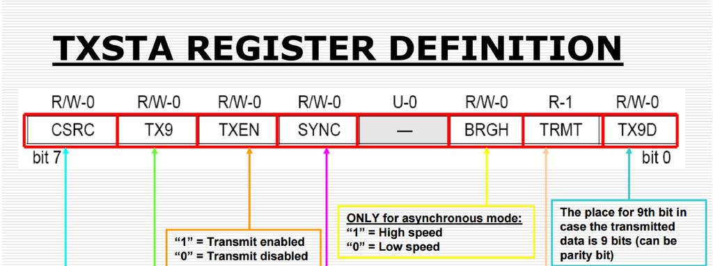
23 TXSTA Register Transmit Status and Control Register 8-bit register Used to select the synchronous/asynchronous modes and data framing size. BRGH bit: select a higher speed for transmission. Default is lower baud rate transmission D6 of TXSTA: determines the framing of data by specifying the number of bits per character

24
25 RCSTA Register Receive Status and Control Register 8-bit register Used to enable the serial port to receive data.

26
27 PIR1 Register Peripheral Interrupt Request Register 1 8-bit register TWO (2) of PIR1 register bits are used by UART: TXIF (transmit interrupt flag) RCIF (receive interrupt flag) We monitor (poll) the TXIF flag bit to make sure that all the bits of the last byte are transmitted before we write another byte into TXREG. By the same logic, we monitor the RCIF flag bit to see if a byte of data has come in yet.

28 PIR1 Register
29 PIR1 Register (cont d)
30 Programming the PIC16 to Transfer Data Serially 1. Load TXSTA register = 20H Indicating asynchronous mode with 8-bit data frame, low baud rate and transmit enabled 2. Make TX pin (PORTC6) an output 3. Load SPBRG to set the baud rate 4. Enabled the serial port: RCSTA<7> (SPEN = 1) 5. Character byte to be transmit is written into TXREG 6. Keep monitor TXIF flag bit of PIR1 register to make sure UART is ready for next byte 7. To transmit next character, go to Step 5
31 Example 1 Write a C program for the PIC16 to transfer the letter 'G' serially at 9600 baud continuously. Assume XTAL = 10 MHz #include <htc.h> _CONFIG ; #define _XTAL PIC configuration void main (void) { TRISC = 0x00; // TX pin (PORTC6) as output TXSTA = 0x20; // 0b ; choose low baud rate, 8-bit, asynchronous mode SPBRG = 15; // or 0x0F; 9600 baud rate, XTAL = 10 MHz TXEN = 1; // enable transmit SPEN = 1; // enable serial port while(1) { TXREG = G ; // place value in buffer while(txif==0); // wait until transmitted } }
32 Write a C program to transfer the message YES serially Example 2 at 9600 baud, 8-bit data, and 1 STOP bit. Do this continuously. Assume XTAL = 10 MHz // PIC configuration void SerTx(unsigned char); // function for sending character void main(void) { TRISC = 0x00; // TX pin (PORTC6) as output TXSTA = 0x20; // 0b ; choose low baud rate, 8-bit, asynchronous mode SPBRG = 15; // or 0x0F; 9600 baud rate, XTAL = 10 MHz TXEN = 1; // enable transmit SPEN = 1; // enable serial port while(1) { SerTx( Y ); SerTx( E ); SerTx( S ); } } void SerTx(unsigned char c) { while(txif==0); // wait for transmitted TXREG = c; // place character in buffer }
33 Example 2 (cont d) // PIC configuration void main(void) { TRISC = 0x00; // TX pin (PORTC6) as output TXSTA = 0x20; // 0b ; choose low baud rate, 8-bit, asynchronous mode SPBRG = 15; // or 0x0F; 9600 baud rate, XTAL = 10 MHz TXEN = 1; // enable transmit SPEN = 1; // enable serial port unsigned char z; unsigned char Mess[] = YES ; while(1) { for (z=0; z<3; z++) // write message { while(txif==0); // wait for transmit TXREG = Mess[z]; // place char in buffer } } }
34 Example 3 Write a C program to send the two messages Normal Speed and High Speed to the serial port. Assuming that SW is connected to pin PORTB0, monitor its status and set the baud rate as follows: SW = 0 : 9600 baud rate SW = 1 : baud rate Assume that XTAL = 10 MHz for both cases. Solution: BRGH = 0 BRGH = 1 UART freq = 156,250 Hz UART freq = 625,000 Hz X = (156,250/9600) - 1 = 15 D X = (625,000/38400) - 1 = 15 D
35 Example 3 (cont d) // PIC configuration #define SW RB0; // PORTB0 as input switch SW void main (void) { TRISB = 0x01; TRISC = 0x00; TXSTA = 0x20; SPBRG = 15; TXEN = 1; SPEN = 1; // PORTB0 as input switch // TX pin (PORTC6) as output // 0b ; choose low baud rate, 8-bit, asynchronous mode // 9600 baud rate, XTAL = 10 MHz // enable transmit // enable serial port unsigned char z; unsigned char Mess1[] = Normal Speed ; unsigned char Mess2[] = High Speed ;
36 Example 3 (cont d) } if (SW==0) { for (z=0; z<12; z++) { while(txif==0); TXREG = Mess1[z]; } } else { TXSTA = TXSTA 0x04; for (z=0; z<10; z++) { while(txif==0); TXREG = Mess2[z]; } } while(1); // stay in loop // wait for transmit // place value in buffer // for high speed (BRGH=1) // wait for transmit // place value in buffer
37 Programming the PIC16 to Receive Data Serially 1. Load RCSTA register = 90H: To enable the continuous receive in addition to the 8-bit data size option 2. Load TXSTA register = 00H: To choose the low baud rate option 3. Load SPBRG to set the baud rate 4. Make RX pin (PORTC7) an input 5. Keep monitor RCIF flag bit of PIR1 register for a HIGH to see if an entire character has been received yet 6. When RCIF = 1, RCREG has a byte, its contents are moved into a safe place 7. To receive next character, go to step 5
38 Example 4 Write a C program to receive bytes of data serially and put them on PORTB. Set the baud rate at 9600, 8-bit data, and 1 STOP bit. // PIC configuration void main(void) { TRICS = 0x00; // set all pin at port B as output TRISC = 0x80; // RX pin (PORTC7) as input, TX pin (PORTC6) as output RCSTA = 0x90; // 0b ; Usart Enable, Continuous receive enable TXSTA = 0x00; // 0b ; choose low baud rate, 8-bit, asynchronous mode SPBRG = 15; // or 0x0F; 9600 baud rate, XTAL = 10 MHz TXEN = 0; // disable transmit SPEN = 1; // enable serial port unsigned char z; while(1) { while(rxif==0); // wait for receive z = RCREG; PORTB = z; // read data // send data to port B } }
39 Hardware Interfacing To communicate over UART or USART, we just need three basic signals which are namely, i) RXD (receive) ii) TXD (transmit) iii) GND (common ground)

40 Hardware Interfacing
41 Summary Serial Communication- data is sent one bit a time, is used in situations where data is sent over significant distances because in parallel communications, where data is sent a byte or more a time, great distances can cause distortion of the data. Additional advantage- allowing transmission over phone lines Asynchronous communication - data is sent one byte at a time and Synchronous communication - data is sent in blocks of bytes Simplex - can sent but cannot receive, Half duplex - can send and receive, but not at the same time and Full duplex - can send and receive at the same time RS232 - standard foe serial communication connectors
42 End of Chapter Life is not so short but that there is always time enough for courtesy Quote by Ralph Waldo Emerson A river cuts the rock not because of its power but because of its consistency. Never lose your hope and keep walking towards your vision!
ELCT 912: Advanced Embedded Systems
 ELCT 912: Advanced Embedded Systems Lecture 10: Applications for Programming PIC18 in C Dr. Mohamed Abd El Ghany, Department of Electronics and Electrical Engineering Programming the PIC18 to transfer
Hi Hsiao-Lung Chan Dept Electrical Engineering Chang Gung University, Taiwan
 PIC18 Serial Port Hi Hsiao-Lung Chan Dept Electrical Engineering Chang Gung University, Taiwan chanhl@mail.cgu.edu.twcgu Serial vs. parallel data transfer 2 Simplex, half-, and full-duplex transfers 3
Chapter 10 Sections 1,2,9,10 Dr. Iyad Jafar
 Starting with Serial Chapter 10 Sections 1,2,9,10 Dr. Iyad Jafar Outline Introduction Synchronous Serial Communication Asynchronous Serial Communication Physical Limitations Overview of PIC 16 Series The
Serial Communication with PIC16F877A
 Serial Communication with PIC16F877A In this tutorial we are going to discuss the serial/uart communication using PIC16F877A. PIC16F877A comes with inbuilt USART which can be used for Synchronous/Asynchronous
ELCT706 MicroLab Session #4 UART Usage for Bluetooth connection PC - PIC
 ELCT706 MicroLab Session #4 UART Usage for Bluetooth connection PC - PIC USART in PIC16F877A Universal Synchronous/Asynchronous Receiver Transmitter - Can receive and transmit - Can be synchronous or Asynchronous
Embedded Systems Programming and Architectures
 Embedded Systems Programming and Architectures Lecture No 10 : Data acquisition and data transfer Dr John Kalomiros Assis. Professor Department of Post Graduate studies in Communications and Informatics
ELCT706 MicroLab Session #4 UART Usage for Bluetooth connection PC - PIC
 ELCT706 MicroLab Session #4 UART Usage for Bluetooth connection PC - PIC USART in PIC16F877A Universal Synchronous/Asynchronous Receiver Transmitter - Can receive and transmit - Can be synchronous or Asynchronous
Parallel IO. Serial IO. Parallel vs. Serial IO. simplex vs half-duplex vs full-duplex. Wires: Full Duplex. Wires: Simplex, Half-duplex.
 Parallel IO Parallel IO data sent over a group of parallel wires. Typically, a clock is used for synchronization. D[15:0] clk Serial IO Serial IO data sent one bit at a time, over a single wire. A clock
Asynchronous Transmission. Asynchronous Serial Communications & UARTS
 Asynchronous Transmission Asynchronous Serial Communications & UARTS 55:036 Embedded Systems and Systems Software asynchronous: transmitter and receiver do not share a common clock or explicitly coordinate
Serial Communication
 Serial Communication What is serial communication? Basic Serial port operation. Classification of serial communication. (UART,SPI,I2C) Serial port module in PIC16F887 IR Remote Controller Prepared By-
Example of Asyncronous Serial Comms on a PIC16F877
 /***************************************************************************************/ /* Example of Asyncronous Serial Comms on a PIC16F877 */ /* Target: PIC16F877 */ /* Baud: 9600 */ /* Bits: 8 */
Section 21. Addressable USART
 21 Section 21. Addressable USART Addressable USART HIGHLIGHTS This section of the manual contains the following major topics: 21.1 Introduction... 21-2 21.2 Control Registers... 21-3 21.3 USART Baud Rate
ELE492 Embedded System Design
 Overview ELE9 Embedded System Design Examples of Human I/O Interfaces Types of System Interfaces Use of standards RS Serial Communication Overview of SPI, I C, L, and CAN Class //0 Eugene Chabot Examples
MCS-51 Serial Port A T 8 9 C 5 2 1
 MCS-51 Serial Port AT89C52 1 Introduction to Serial Communications Serial vs. Parallel transfer of data Simplex, Duplex and half-duplex modes Synchronous, Asynchronous UART Universal Asynchronous Receiver/Transmitter.
Experiment 7:The USART
 University of Jordan Faculty of Engineering and Technology Department of Computer Engineering Embedded Systems Laboratory 0907334 7 Experiment 7:The USART Objectives Introduce the USART module of the PIC
FULL DUPLEX BIDIRECTIONAL UART COMMUNICATION BETWEEN PIC MICROCONTROLLERS
 FULL DUPLEX BIDIRECTIONAL UART COMMUNICATION BETWEEN PIC MICROCONTROLLERS Dhineshkaarthi K., Sundar S., Vidhyapathi C. M. and Karthikeyan B. M. Tech, School of Electronics Engineering, VIT University,
ECE 354 Introduction to Lab 1. February 5 th, 2003
 ECE 354 Introduction to Lab 1 February 5 th, 2003 Lab 0 Most groups completed Lab 0 IDE Simulator Questions? ICD Questions? What s the difference? ECE 354 - Spring 2003 2 Addition to Honesty Policy It
TKT-3500 Microcontroller systems
 TKT-3500 Microcontroller systems Lec 3a Serial Input/output Ville Kaseva Department of Computer Systems Tampere University of Technology Fall 2010 Sources Original slides by Erno Salminen Robert Reese,
The University of Texas at Arlington Lecture 21_Review
 The University of Texas at Arlington Lecture 21_Review CSE 5442/3442 Agenda Tuesday December 1st Hand back Homework 7,8 and 9. Go over questions and answers Exam 3 Review Note: There will be a take home
Embedded Systems and Software. Serial Communication
 Embedded Systems and Software Serial Communication Slide 1 Using RESET Pin on AVRs Normally RESET, but can be configured via fuse setting to be general-purpose I/O Slide 2 Disabling RESET Pin on AVRs Normally
Embedded Systems and Software
 Embedded Systems and Software Serial Communication Serial Communication, Slide 1 Lab 5 Administrative Students should start working on this LCD issues Caution on using Reset Line on AVR Project Posted
ELEG3923 Microprocessor Ch.10 Serial Port Programming
 Department of Electrical Engineering University of Arkansas ELEG3923 Microprocessor Ch.10 Serial Port Programming Dr. Jingxian Wu wuj@uark.edu OUTLINE 2 Basics of Serial Communication Serial port programming
8051 Timers and Serial Port
 8051 Timers and Serial Port EE4380 Fall 2001 Class 10 Pari vallal Kannan Center for Integrated Circuits and Systems University of Texas at Dallas Timer: Mode 1 Operation (recap) 16 bit counter. Load the
8051 Serial Communication
 8051 Serial Communication Basics of serial communication Parallel: transfers eight bits of data simultaneously over eight data lines expensive - short distance fast Serial : one bit at a time is transferred
Serial Communication Prof. James L. Frankel Harvard University. Version of 2:30 PM 6-Oct-2015 Copyright 2015 James L. Frankel. All rights reserved.
 Serial Communication Prof. James L. Frankel Harvard University Version of 2:30 PM 6-Oct-2015 Copyright 2015 James L. Frankel. All rights reserved. Overview of the Serial Protocol Simple protocol for communicating
8051 Serial Port. EE4380 Fall02 Class 10. Pari vallal Kannan. Center for Integrated Circuits and Systems University of Texas at Dallas
 8051 Serial Port EE4380 Fall02 Class 10 Pari vallal Kannan Center for Integrated Circuits and Systems University of Texas at Dallas Serial Comm. - Introduction Serial Vs Parallel Transfer of data Simplex,
IE1206 Embedded Electronics
 IE1206 Embedded Electronics Le1 Le3 Le4 Le2 Ex1 Ex2 PIC-block Documentation, Seriecom Pulse sensors I, U, R, P, serial and parallell KC1 LAB1 Pulsesensors, Menuprogram Start of programing task Kirchoffs
Hong Kong Institute of Vocational Education Digital Electronics & Microcontroller. 8. Microcontroller
 8. Microcontroller Textbook Programming Robot Controllers, Myke Predko, McGraw Hill. Reference PIC Robotics: A Beginner's Guide to Robotics Projects Using the PIC Micro, John Iovine, McGraw Hill. Embedded
Kit Contents. Getting Started Kits. Board. Board
 Kit Contents Getting Started Kits Each kit has the following items: Board with microcontroller (18(L)F4620) Power brick for the board. Programmer, and power brick for programmer. USB logic analyzer Digital
Hello, and welcome to this presentation of the STM32 Low Power Universal Asynchronous Receiver/Transmitter interface. It covers the main features of
 Hello, and welcome to this presentation of the STM32 Low Power Universal Asynchronous Receiver/Transmitter interface. It covers the main features of this interface, which is widely used for serial communications.
APPLICATION NOTE 2361 Interfacing an SPI-Interface RTC with a PIC Microcontroller
 Maxim/Dallas > App Notes > REAL-TIME CLOCKS Keywords: DS1305, SPI, PIC, real time clock, RTC, spi interface, pic microcontroller Aug 20, 2003 APPLICATION NOTE 2361 Interfacing an SPI-Interface RTC with
Hello, and welcome to this presentation of the STM32 Universal Synchronous/Asynchronous Receiver/Transmitter Interface. It covers the main features
 Hello, and welcome to this presentation of the STM32 Universal Synchronous/Asynchronous Receiver/Transmitter Interface. It covers the main features of this USART interface, which is widely used for serial
The MICROPROCESSOR PRINCIPLES AND APPLICATIONS Lab 7
 The MICROPROCESSOR PRINCIPLES AND APPLICATIONS Lab 7 Timer, USART Cheng-Chien Su 蘇正建 Home Automation, Networking, and Entertainment Lab Dept. of Computer Science and Information Engineering National Cheng
Serial Communications
 1 Serial Interfaces 2 Embedded systems often use a serial interface to communicate with other devices. Serial Communications Serial implies that it sends or receives one bit at a time. Serial Interfaces
Sender Receiver Sender
 EEE 410 Microprocessors I Spring 04/05 Lecture Notes # 19 Outline of the Lecture Interfacing the Serial Port Basics of Serial Communication Asynchronous Data Communication and Data Framing RS232 and other
Lab 6 RS-232 Communication The following routines are provided for devices with a single USART peripheral:
 Still More Lab 6 Considerations; Embedded System Power Issues; Project Information Lab 6 RS-232 Communication The following routines are provided for devices with a single USART peripheral: BusyUSART CloseUSART
 Features 2.4 GHz Carrier Frequency RS232 UART interface with variable baud rate Input supply voltage: 5V to 12V 255 possible Channels frequencies (0 to 255) Programmable Device Address (255 per channel)
Interrupts and Serial Communication on the PIC18F8520
 Interrupts and Serial Communication on the PIC18F8520 Kyle Persohn COEN 4720 Fall 2011 Marquette University 6 October 2011 Outline 1 Background Serial Communication PIC18 Interrupt System 2 Customizing
8051SERIAL PORT PROGRAMMING
 8051SERIAL PORT PROGRAMMING Basics of Serial Communication Computers transfer data in two ways: Parallel Often 8 or more lines (wire conductors) are used to transfer data to a device that is only a few
11.4 THE SERIAL PERIPHERAL INTERFACE (SPI)
") Synchronous Serial IO 331 TRISC6 TRISC[6] Must be 0 so that RC6/TX/CK pin is an output. TRISC7 TRISC[7] Must be 1 so that RC7/RX/DT pin is an input. 11.4 THE SERIAL PERIPHERAL INTERFACE (SPI) The Serial
Synchronous Serial IO 331 TRISC6 TRISC[6] Must be 0 so that RC6/TX/CK pin is an output. TRISC7 TRISC[7] Must be 1 so that RC7/RX/DT pin is an input. 11.4 THE SERIAL PERIPHERAL INTERFACE (SPI) The Serial
Demo 17 - Receiving data from Host through Serial Port. Introduction:
 Introduction: This demo program gives an idea about receiving data from the host using the serial port in asynchronous mode at 500 baud using serial port 0. The received data will be stored in the RAM
CAT Controlled Fract-N Synthesizer
 CAT Controlled Fract-N Synthesizer Overview The unit is a PIC based interface that takes in serial Computer Aided Transceiver (CAT) commands and translates them into the register values to programme an
DIPLOMA THESIS DETECTION AND PREVENTION OF FAULTY PINS
 UNIVERSITY POLITEHNICA OF BUCHAREST FACULTY OF ELECTRONICS, TELECOMMUNICATIONS AND INFORMATION TECHNOLOGY DETECTION AND PREVENTION OF FAULTY PINS DIPLOMA THESIS Submitted in partial fulfillment of the
To be familiar with the USART (RS-232) protocol. To be familiar with one type of internal storage system in PIC (EEPROM).
 protocol. To be familiar with one type of internal storage system in PIC (EEPROM).") Lab # 6 Serial communications & EEPROM Objectives To be familiar with the USART (RS-232) protocol. To be familiar with one type of internal storage system in PIC (EEPROM). Serial Communications Serial
Lab # 6 Serial communications & EEPROM Objectives To be familiar with the USART (RS-232) protocol. To be familiar with one type of internal storage system in PIC (EEPROM). Serial Communications Serial
Super Awesome Multitasking Microcontroller Interface for Electromechanical Systems (S.A.M.M.I.E.S.) Pinball Table
 Pinball Table") Super Awesome Multitasking Microcontroller Interface for Electromechanical Systems (S.A.M.M.I.E.S.) Pinball Table Group 13 April 29 th, 2008 Faculty Advisor: Professor Haibo He Group Members: William McGuire
Super Awesome Multitasking Microcontroller Interface for Electromechanical Systems (S.A.M.M.I.E.S.) Pinball Table Group 13 April 29 th, 2008 Faculty Advisor: Professor Haibo He Group Members: William McGuire
19.1. Unit 19. Serial Communications
 9. Unit 9 Serial Communications 9.2 Serial Interfaces Embedded systems often use a serial interface to communicate with other devices. Serial implies that it sends or receives one bit at a time. µc Device
Serial communication
 Serial communication CSCI 255: Introduction to Embedded Systems Keith Vertanen Copyright 2011 Serial communication Terminology RS-232 protocol Baud rates Flow control Example Overview Develop functions
Chapter 13. PIC Family Microcontroller
 Chapter 13 PIC Family Microcontroller Lesson 06 Special Function Registers for Control and status registers for the peripherals, input/output and Interrupt SFRs SFRs at the addresses of internal RAM/register
e-pg Pathshala Subject : Computer Science Paper: Embedded System Module: Serial Port Communication Module No: CS/ES/11 Quadrant 1 e-text
 e-pg Pathshala Subject : Computer Science Paper: Embedded System Module: Serial Port Communication Module No: CS/ES/11 Quadrant 1 e-text In this lecture, serial port communication will be discussed in
8051 Microcontroller
 8051 Microcontroller The 8051, Motorola and PIC families are the 3 leading sellers in the microcontroller market. The 8051 microcontroller was originally developed by Intel in the late 1970 s. Today many
Interrupt Programming: Interrupts vs. Polling Method:
 UNIT 4: INTERRUPT PROGRAMMING & SERIAL COMMUNICATION WITH 8051: Definition of an interrupt, types of interrupts, Timers and Counter programming with interrupts in assembly. 8051 Serial Communication: Data
UART: Universal Asynchronous Receiver & Transmitter
 ECE3411 Fall 2015 Lecture 2a. UART: Universal Asynchronous Receiver & Transmitter Marten van Dijk, Syed Kamran Haider Department of Electrical & Computer Engineering University of Connecticut Email: {vandijk,
Interfacing a Hyper Terminal to the Flight 86 Kit
 Experiment 6 Interfacing a Hyper Terminal to the Flight 86 Kit Objective The aim of this lab experiment is to interface a Hyper Terminal to 8086 processor by programming the 8251 USART. Equipment Flight
EE 354 November 13, 2017 ARM UART Notes
 EE 354 November 13, 2017 ARM UART Notes For serial communications you should be familiar with the following terms: UART/USART Baud rate Synchronous/Asynchronous communication Half-Duplex/Full-Duplex The
Design, Development & Implementation of a Temperature Sensor using Zigbee Concepts
 Design, Development & Implementation of a Temperature Sensor using Zigbee Concepts T.C.Manjunath, Ph.D. ( IIT Bombay ) & Fellow IETE, Ashok Kusagur, Shruthi Sanjay, Saritha Sindushree, C. Ardil Abstract
CoE3DJ4 Digital Systems Design. Chapter 5: Serial Port Operation
 CoE3DJ4 Digital Systems Design Chapter 5: Serial Port Operation Serial port 8051 includes an on-chip serial port Hardware access to the port is through TXD and RXD (Port 3 bits 1 and 0) Serial port is
Emulating an asynchronous serial interface (USART) via software routines
 via software routines") Microcontrollers ApNote AP083101 or æ additional file AP083101.EXE available Emulating an asynchronous serial interface (USART) via software routines Abstract: The solution presented in this paper and
Microcontrollers ApNote AP083101 or æ additional file AP083101.EXE available Emulating an asynchronous serial interface (USART) via software routines Abstract: The solution presented in this paper and
SCB-C08 USB to RS232/422/485 Converter
 SCB-C08 USB to RS232/422/485 Converter USB Interface RS-232 signal RS-422 signal: RS-485 signal: Cable Type Transmission distance Signal LED Direct power from USB port Power consumption: Compliant with
Maxim > Design Support > Technical Documents > Application Notes > Microcontrollers > APP 4465
 Maxim > Design Support > Technical Documents > Application Notes > Microcontrollers > APP 4465 Keywords: MAXQ, MAXQ610, UART, USART, serial, serial port APPLICATION NOTE 4465 Using the Serial Port on the
PIC-I/O Multifunction I/O Controller
 J R KERR AUTOMATION ENGINEERING PIC-I/O Multifunction I/O Controller The PIC-I/O multifunction I/O controller is compatible with the PIC-SERVO and PIC-STEP motor control modules and provides the following
Informatics for industrial applications
 Informatics for industrial applications Lecture 5 - Peripherals: USART and DMA Martino Migliavacca martino.migliavacca@gmail.com October 20, 2011 Outline 1 Introduction to USART Introduction Synchronous
Microcontroller basics
 FYS3240 PC-based instrumentation and microcontrollers Microcontroller basics Spring 2017 Lecture #4 Bekkeng, 30.01.2017 Lab: AVR Studio Microcontrollers can be programmed using Assembly or C language In
RFID: Read and Display V2010. Version 1.1. Sept Cytron Technologies Sdn. Bhd.
 PR8-B RFID: Read and Display V2010 Version 1.1 Sept 2010 Cytron Technologies Sdn. Bhd. Information contained in this publication regarding device applications and the like is intended through suggestion
Serial Communication. Simplex Half-Duplex Duplex
 1.5. I/O 135 Serial Communication Simplex Half-Duplex Duplex 136 Serial Communication Master-Slave Master Master-Multi-Slave Master Slave Slave Slave (Multi-)Master Multi-Slave Master Slave Slave Slave
COMP2121: Microprocessors and Interfacing
 COMP2121: Microprocessors and Interfacing Lecture 25: Serial Input/Output (II) Overview USART (Universal Synchronous and Asynchronous serial Receiver and Transmitter) in AVR http://www.cse.unsw.edu.au/~cs2121
 Overview RFSv4.3 is a RF module providing easy and flexible wireless data transmission between devices. It is based on AVR Atmega8 with serial output which can be interfaced directly to PC. Features 2.4
ARM HOW-TO GUIDE Interfacing GPS with LPC2148 ARM
 ARM HOW-TO GUIDE Interfacing GPS with LPC2148 ARM Contents at a Glance ARM7 LPC2148 Primer Board... 3 GPS (Global Positioning Systems)... 3 Interfacing GPS... 4 Interfacing GPS with LPC2148... 5 Pin Assignment
Serial Communications
 April 2014 7 Serial Communications Objectives - To be familiar with the USART (RS-232) protocol. - To be able to transfer data from PIC-PC, PC-PIC and PIC-PIC. - To test serial communications with virtual
LCD. Configuration and Programming
 LCD Configuration and Programming Interfacing and Programming with Input/Output Device: LCD LCD (liquid crystal display) is specifically manufactured to be used with microcontrollers, which means that
DHANALAKSHMI COLLEGE OF ENGINEERING, CHENNAI DEPARTMENT OF ELECTRICAL AND ELECTRONICS ENGINEERING. EE Microcontroller Based System Design
 DHANALAKSHMI COLLEGE OF ENGINEERING, CHENNAI DEPARTMENT OF ELECTRICAL AND ELECTRONICS ENGINEERING EE6008 - Microcontroller Based System Design UNIT III PERIPHERALS AND INTERFACING PART A 1. What is an
USART Functions. putsusart puts1usart puts2usart putrsusart putrs1usart putrs2usart. ReadUSART Read1USART Read2USART getcusart getc1usart getc2usart
 1 of 11 USART Functions TABLE OF CONTENTS 1 Introduction 2 Function Descriptions 2.1 BusyUSART Busy1USART Busy2USART 2.2 CloseUSART Close1USART Close2USART 2.3 DataRdyUSART DataRdy1USART DataRdy2USART
4D Picaso Touchscreen Display board datasheet EB
 4D Picaso Touchscreen Display board datasheet EB076-00 00-1 CONTENTS 1. About this document. 2 2. General Information.. 3 3. Board layout... 3 4. Testing this product... 4 5. Circuit description.. 4 Appendix
ECE251: Thursday November 8
 ECE251: Thursday November 8 Universal Asynchronous Receiver & Transmitter Text Chapter 22, Sections 22.1.1-22.1.4-read carefully TM4C Data Sheet Section 14-no need to read this A key topic but not a lab
Section Description DIP Switch Extension Bus Port Port for Microcontroller Port
 1. Upto 256 RC SERVOs can be connected together using Serial Lines. 2. Angle and speed can be set. Angle and speed can be set independently set for each SERVO. 3. 4800bps or 9600 bps baud rate are supported
Basics of UART Communication
 Basics of UART Communication From: Circuit Basics UART stands for Universal Asynchronous Receiver/Transmitter. It s not a communication protocol like SPI and I2C, but a physical circuit in a microcontroller,
UNIVERSITY OF NAIROBI FACULTY OF ENGINEERING DEPARTMENT OF ELECTRICAL AND INFORMATION ENGINEERING
 UNIVERSITY OF NAIROBI FACULTY OF ENGINEERING DEPARTMENT OF ELECTRICAL AND INFORMATION ENGINEERING PROJECT: A MICROCONTROLLER BASED WIRELESS E-NOTICE BOARD PROJECT INDEX: 06 NAME: LUBANGA DENNIS WASIOYA
Outlines. PIC Programming in C and Assembly. Krerk Piromsopa, Ph.D. Department of Computer Engineering Chulalongkorn University
 PIC ming in C and Assembly Outlines Microprocessor vs. MicroController PIC in depth PIC ming Assembly ming Krerk Piromsopa, Ph.D. Department of Computer Engineering Chulalongkorn University Embedded C
Universal Asynchronous Receiver Transmitter Communication
 Universal Asynchronous Receiver Transmitter Communication 13 October 2011 Synchronous Serial Standard SPI I 2 C Asynchronous Serial Standard UART Asynchronous Resynchronization Asynchronous Data Transmission
Embedded programming, AVR intro
 Applied mechatronics, Lab project Embedded programming, AVR intro Sven Gestegård Robertz Department of Computer Science, Lund University 2017 Outline 1 Low-level programming Bitwise operators Masking and
ET-PIC 24 WEB-V1. o Central Processing Unit (CPU) o System. o nanowatt Power Managed Modes. o Analog Features
 o System. o nanowatt Power Managed Modes. o Analog Features") ET-PIC 24 WEB-V1 ET-PIC 24 WEB-V1 is PIC Board Microcontroller from Microchip that uses 16 Bit No.PIC24FJ128GA008 Microcontroller for processing data and develops board. The remarkable specification of
ET-PIC 24 WEB-V1 ET-PIC 24 WEB-V1 is PIC Board Microcontroller from Microchip that uses 16 Bit No.PIC24FJ128GA008 Microcontroller for processing data and develops board. The remarkable specification of
e-pg Pathshala Subject : Computer Science Paper: Embedded System Module: Serial Port Programming in Assembly Module No: CS/ES/12 Quadrant 1 e-text
 e-pg Pathshala Subject : Computer Science Paper: Embedded System Module: Serial Port Programming in Assembly Module No: CS/ES/12 Quadrant 1 e-text In this lecture, serial communication control register
Emulating an asynchronous serial interface (ASC0) via software routines
 via software routines") Microcontrollers ApNote AP165001 or æ additional file AP165001.EXE available Emulating an asynchronous serial interface (ASC0) via software routines Abstract: The solution presented in this paper and in
Microcontrollers ApNote AP165001 or æ additional file AP165001.EXE available Emulating an asynchronous serial interface (ASC0) via software routines Abstract: The solution presented in this paper and in
Parallel-to-Serial and Serial-to-Parallel Converters
 Session 1532 Parallel-to-Serial and Serial-to-Parallel Converters Max Rabiee, Ph.D., P.E. University of Cincinnati Abstract: Microprocessors (MPUs) on a computer motherboard communicate in a parallel format
University of Texas at El Paso Electrical and Computer Engineering Department. EE 3176 Laboratory for Microprocessors I.
 University of Texas at El Paso Electrical and Computer Engineering Department EE 3176 Laboratory for Microprocessors I Fall 2016 LAB 08 UART Communication Goals: Learn about UART Communication and the
Input-Output Organization
 Ted Borys - CSI 404 5/1/2004 Page 11-1 Section 11 Input-Output Organization ASCII Character Set 94 printable characters Upper & lowercase letters 10 numerals Special characters such as $, @, #, % 34 control
Lab 8 RS232 October 22, 2015
 Lab 8 RS232 October 22, 2015 In this lab you will use the Serial Communications Interface (SCI) system on the HCS12 microcontroller to send and receive characters using the RS232 signal format. You will
Serial I-O for Dinesh K. Sharma Electrical Engineering Department I.I.T. Bombay Mumbai (version 14/10/07)
") Serial I-O for 8051 Dinesh K. Sharma Electrical Engineering Department I.I.T. Bombay Mumbai 400 076 (version 14/10/07) 1 Motivation Serial communications means sending data a single bit at a time. But
Serial I-O for 8051 Dinesh K. Sharma Electrical Engineering Department I.I.T. Bombay Mumbai 400 076 (version 14/10/07) 1 Motivation Serial communications means sending data a single bit at a time. But
Laboratory 5 Communication Interfaces
 Laboratory 5 Communication Interfaces Embedded electronics refers to the interconnection of circuits (micro-processors or other integrated circuits) with the goal of creating a unified system. In order
Input/Output Ports and Interfacing
 Input/Output Ports and Interfacing ELEC 330 Digital Systems Engineering Dr. Ron Hayne Images Courtesy of Ramesh Gaonkar and Delmar Learning Basic I/O Concepts Peripherals such as LEDs and keypads are essential
Serial Peripheral Interface Bus SPI
 Serial Peripheral Interface Bus SPI SPI Bus Developed by Motorola in the mid 1980 s Full-duplex, master-slave serial bus suited to data streaming applications for embedded systems Existing peripheral busses
Lecture 10. Serial Communication
 Lecture 10 Serial Communication Serial Communication Introduction Serial communication buses Asynchronous and synchronous communication UART block diagram UART clock requirements Programming the UARTs
8051 Peripherals. On-Chip Memory Timers Serial Port Interrupts. Computer Engineering Timers
 8051 Peripherals On-Chip Memory Timers Serial Port Interrupts Computer Engineering 2 2-1 8051 Timers 8051 Timers The 8051 has 2 internal 16-bit timers named Timer 0 and Timer 1 Each timer is a 16-bit counter
AVR Training Board-I. VLSI Design Lab., Konkuk Univ. LSI Design Lab
 AVR Training Board-I V., Konkuk Univ. Tae Pyeong Kim What is microcontroller A microcontroller is a small, low-cost computeron-a-chip which usually includes: An 8 or 16 bit microprocessor (CPU). A small
USB232 board EB Technical datasheet
 USB232 board EB039-00-1 Technical datasheet Contents 1. About this document...2 2. General information...3 3. Board layout...4 4. Testing this product...5 5. Circuit description...7 Appendix 1 Circuit
LABORATORY MANUAL Interfacing LCD 16x2, Keypad 4x4 and 7Segment Display to PIC18F4580
 LABORATORY MANUAL Interfacing LCD 16x2, Keypad 4x4 and 7Segment Display to PIC18F458 1. OBJECTIVES: 1.1 To learn how to interface LCD 16x2, Keypad 4x4 and 7Segment Display to the microcontroller. 1.2 To
The Atmel ATmega168A Microcontroller
 Ming Hsieh Department of Electrical Engineering EE 459Lx - Embedded Systems Design Laboratory The Atmel ATmega168A Microcontroller by Allan G. Weber 1 Introduction The Atmel ATmega168A is one member of
User s Manual Closer to Real, Zigbee Module ZIG-100. Wireless Communication. ROBOTIS CO.,LTD
 User s Manual 2006-07-06 Closer to Real, Wireless Communication ROBOTIS CO.,LTD. www.robotis.com +82-2-2168-8787 Contents 1. Page 02 2. Zigbee Setting Page 06 3. PC Interface Zig Board Schematic Page 10
ELAN DIGITAL SYSTEMS LTD. CF428 COMPACT FLASH CF+ CARD USER S GUIDE
 ELAN DIGITAL SYSTEMS LTD. LITTLE PARK FARM ROAD, SEGENSWORTH WEST, FAREHAM, HANTS. PO15 5SJ. TEL: (44) (0)1489 579799 FAX: (44) (0)1489 577516 e-mail: support@pccard.co.uk website: http://www.pccard.co.uk
Am186ER/Am188ER AMD continues 16-bit innovation
 Am186ER/Am188ER AMD continues 16-bit innovation 386-Class Performance, Enhanced System Integration, and Built-in SRAM Am186ER and Am188ER Am186 System Evolution 80C186 Based 3.37 MIP System Am186EM Based
ATmega128. Serial Communication (RS-232C)
") ATmega128 Serial Communication (RS-232C) RS-232C EIA (Electronics Industries Association) DTE (Data Terminal Equipment) DCE (Data Communication Equipment) RS-232C Signals 핀번호 (Pin No.) 명칭 (Signal Name)
ATmega128 Serial Communication (RS-232C) RS-232C EIA (Electronics Industries Association) DTE (Data Terminal Equipment) DCE (Data Communication Equipment) RS-232C Signals 핀번호 (Pin No.) 명칭 (Signal Name)