DVR Server Manual. DVR system USER S GUIDE
|
|
|
- Dana Sanders
- 6 years ago
- Views:
Transcription
1 DVR system USER S GUIDE I
2 Contents Chapter1 Start up and Main Interface Installation Disk management Start up Main Interface Show tips Screen menu Interface description System Menu Network panel PTZ Control panel Color and Audio adjustment Matrix & display DI/DO Control Chapter2 Local setup System setup System setup Network setup Boot setup Camera setup II
3 2.2.1 Camera setup Group setup Sensor setup Sensor setup Group setup PTZ & Linkage setup PTZ protocol setup Motion detection relay & remote client alert & Sms setup setup SMS setup Digital matrix setup Matrix setup Display setup Password setup User information User right setup Chapter3 IP Camera Setup Functional buttons Server setup Channel setup III
4 3.4 PTZ control Sensor setup Alarm setup Chapter4 Playback Main interface Select playback channel Select date Select camera Select file Play file and related operations Capture picture Create clip file Create file clip Backup by time: View Backup file Search captured picture Fast search Camera status Synchronic play Smart search Show files IV
5 4.10 POS Playback ACU Playback ICON Playback Chapter5 IE client Functions of IE Client Main interface Connection operations Connection/Record status Partition mode PTZ Control Quit program Local search Display setup and data information Playing operation area Remote search Fast download record data Chapter6 Mobile Client Recommended Mobile Phone Requirements Download software Install and connect Installation V
6 6.3.2 Connection Login Interface Camera List PTZ control Chapter7 Appendixes Appendix A: Fast key reference Appendix B: Audio preview Appendix D: How to use Copy File folder Appendix E: Explanation about NV series DVR board Appendix F: Frequent Asked Questions VI
7 Introductions: Thank you for purchasing our DVR system. This operation manual is to introduce how to set DVR system and explain all functions for using the system effectively and stably. You should be better go through this manual thoroughly before installing this DVR system and you can get this manual from your dealer or contact us directly. System features: -Support H.264 compression and low HDD cost -Access web through LAN or WAN. -Real time full-motion video-capture & display (Up to 64 channel video input) -Real time high-speed recording(up to 30 fps per channel) -Synchronous audio recording (optional) -Motion detection (Whole area or up to 12 detection zones per channel) -Normal recording (continuous) and event recording (Motion detection or external sensor) -Electron Map pop-up when alarm happen -System operating and alarm logging -Alarm before recording -Remote recording -Send alarm message automatically. -Send alarm image to box as attachment automatically -Matrix display and group display -Duplex mode (Recording while playback) -Network support (Remote access via LAN, Ethernet, PSTN, ISDN, ADSL) -P/T/Z/F & speed demo control on keyboard -Search/playback by date/time directory (random-access) -Backup & burn CD directly -Remote talking between server and client or server and server -Support three types of resolution (1024*768 pixels, 1024*768 pixels, 1028*1024 pixels) Important Information: For optimal performance of your system, it is important to follow these recommendations. 1 We recommend that you divide your hard disk into two partitions (E.g. C and D:) at least. The first partition is used to install Windows OS and system software, the other for storing record files. 2 Please use appropriate motherboard and display card. Contact your dealers or our support engineers if you have any questions. 7
8 Recommended System Requirements Chipset: Intel 845PE, 865PE, 875PE, 915P, 945P Motherboard: Intel: D915/945PCY, D865PERL Asus: P4P800SE, P5P800 MSI: 865PE Neo2-F, 915/925/945; Gigabit: GA-865GME, GA-945PL-G etc Video Card: ATI Radeon MB, ATI Radeon MB, ATI X500, X550, X700 etc; Processor: Intel Pentium 4 2.4GHz or better Memory: 512MB minimum 8
9 Chapter1 Start up and Main Interface 1.1 Installation 1) Before running DVR server, please make sure all connectors are firmly connected. 2) After Installing compressed card and its driver(please refer to Appendix C: Update drivers of compressed card ), operating system will identify the compressed cards automatically 错误! 未定义书签 1.2 Disk management Disk Management interface will be displayed after completing installation Disk Drives Display the disk and its format. Total Size(M) Display the disk s total space. Free Space(M) Display the free size of the disk. Allotted Data Package Display the number of data packages which have been allocated in disk Residual Data Package Display the rest number of data package in disk New Data Package Select the number of the new data package. 9
10 Select the new data package number which you want in the drop-down list. The software will calculate the rest space automatically. Notice: 1.the space of a package is 256M by default and cannot be changed. 1.3 Start up 2 If there is no any package is created in disk,the Dvr server will not record. After installing, a shortcut icon will be displayed on desktop, Left-Double-Click it to access DVR system. The main interface is as follow: 10

11 Note: the software support 1024*768, 1280*768, 1280*1024 three display ways, dvr adjust display mode automatically according to user VGA setup. 1.4 Main Interface Show tips 1. When the mouse moves closely or stops above a button, a text tip will be shown to interpret the function of it immediately. 2. Zoom in/out video image: Left-Double-Click a camera window to zoom in/out video image (or press F11 on the keyboard). 3. System will detect cards and read the total number automatically, and the corresponding number buttons will be displayed dynamically. 4. Recording status: a. This icon means the system is recording normally. b. This icon means the system is recording manually. c. This icon means the system is recording in motion detection. d. This icon means the system is recording in sensor detection. 11
12 1.4.2 Screen menu Press TAB key or Page UP (select next camera window) and Page Down (select previous camera window) key on keyboard to select one live camera window. 1. Full screen Single-Right- Click image area, it will popup a menu, then select full screen to change display mode to full screen (or press F12 on the keyboard). When you want to resume origin mode, you should Single-Right- Click image area and select Restore display. 2. Instant playback Single-Right-Click desired camera window and select Instant playback (except IP Camera, it can just play back instantly in the window that is not used). After that, choose a time from the submenu, and then system will play back video data of current camera in current window according to your selection (E.g.: you select 1min, system will play back previous 1 minute video data of current camera in current window). Also, you can play back video data of one current live camera in a window that is not used by any cameras (always black background with no Video Loss information, IP Camera can only play back instantly in those windows): Select a window, and then Single-Right-Click it to select Instant playback. Finally, choose a time and the camera you want to playback, and then system will play back video data in current window according to your selection. The window that is playing back video data will indicate a yellow border to be different from the live windows. ` 12
13 In the course of the instant playback, you can press Space key to switch the play/pause status or direction key and to play next and previous frame. If you want to stop the instant playback, you can Single-Right-Click the play backing window, and select End playback. While instant playback is in processing, if you want to play it again, you can select Review playback function. You can press Space key to switch the play/pause status or direction. In pause status, you can press key and to play next and previous frame. when the screen plays, you can press and to control the speed of playing, also, in play status you can press and to play in normal speed and play it again. 3. Alarm popup Single-Right-Click video image area in main interface and select Start alarm popup after you set Alarm camera popup interval in system setup, otherwise, it can t be selected with gray. After that when there has a motion detection alarm (set in PTZ & Linkage setup and Motion detection setup) or an alarm triggered by sensor (set in Sensor setup), system will display alarm cameras in sequence. But this function does not include IP camera, even IP camera have alarms, there images will not pop up. When you want to end this function, you can Single-Right-Click video image area and select Pause alarm popup. 4. OSD Adjustment Single-Right-Click video image area in main interface and select OSD Adjustment to adjust the position of OSD (IP Camera does not have this function; you can set the OSD position in IP Camera setup remotely). 13

14 OSD include time and channel name. you can drag time or channel name to where you want directly in screen,then press button to save it or press button to resume time and channel name to default position. 5. IP Camera setup For this function, it is only available when you Right-single-Click image of IP camera. It will describe in Chapter 3 IP Camera Setup Interface description 1. Partition mode Press button to set the window s partition mode of the main screen. There are many types partition; the available partition is determined by the total channels of card, you can select the suitable partition according to the 14
15 number of video inputs, the partition number which is bigger than total channel is not available with gray. 2. Videos-play-in-sequence mode switch Press button to switch between playing all cameras in current windows in sequence and not when the current partition number is smaller than the total channels of card. 3. Emergency recording button Press button to trigger recording of all cameras for 30 seconds even if they have been set to record by any other modes. This function is useful to deal with emergency where quick response is required. 4. Image capture Press button to save a still image of selected camera to local hard disk for reviewing or print. 5. Manual record switch Press button to record manually and press it again to stop manual recording for selected camera. 6. Information display panel This panel shows day of the week, current date, current time, total free 15

16 hard disk space, current record disk and description of selected camera. 7. Local setup submenu Press button to enter Local setup submenu. 8. Playback submenu Press button to enter Playback submenu to search local video/audio data. 9. System lock Press button to prevent unauthorized user to operate system. Press this button again; the unlock dialog box will be displayed. Input your User ID and password then press OK to unlock it. Default User ID is admin, no password. Note: If the DVR system is not configured as User Manage Mode, the lock button will be unusable and allow any client s access (even in client program, user name and password will be useless) 10. Minimize button Press keyboard). button to minimize the main window (or press WIN + Z on 11. Exit program Press button to exit program. 16

17 After clicking this button, a dialog will display. Click OK to quit DVR system System Menu 1. Backup System Parameters Select this function to export system configurations. 2. Import System Parameters Select this function to import system configurations. 3. DVD/CD Disc backup directly Select this function to burn video data to DVD or CD, it is same to burn DVD/CD function in Playback. 4. Execute a external program Select this function to execute an external program 17
18 5. Remote chatting Select this option to connect a remote Client or Server for a live chatting via IP address, but first, you should be sure you have installed audio card and Microphone in each PC. 6. Write working log This is useful to record events that occur during the operator s shift. 7. Open Explorer When keyboard is locked, Users can operate window resource via explorer. 8. Play back to Tv Monitor In DVR system, the recording data can be transmitted to TV monitor via Matrix card 9. Open Screen Keyboard This function allow user to use soft keyboard, you can press this bar to open the screen keyboard. Also, in the setup interface you can Left-Double-Click the blank to open this keyboard. User can close this keyboard manually. 10. Motion detection Setup 18

19 By default, the entire screen is set as motion detection area where is indicated with green border around the image. To mask a specific area, you can click button to cancel the full screen detection border; then Left-Single-Click and drag a rectangle. A green rectangle will mark the area of it. Also, you can set any other areas. Any activities in the motion detection areas will trigger recording, depending on the reaction mode; and alarms may be generated along with electronic map icons flashing in alert mode. Click button to test the sensitivity of motion detection. The sensitivity can be adjusted by dragging the slider bars below the motion detection window, The Sensitivity value bar is used to adjust the sensitivity of the area you selected, The motion value bar is used to set the minimum acreage of full screen to trigger alarm. Its unit is percent, if the acreage of motion area exceeds the setting percents of the areas you selected, system will trigger alarm. The default value of Sensitivity and Motion is 6 and 1%. Notice: motion sensitivity value will affect the accuracy of smart search 19

20 Add mask / Delete mask Press button to set the area to be shielded. If there are some areas that you don t want to show, you can draw those areas with mouse till they change to be black. You can set several cover areas. Press this button again to finish adding Press button to delete all cover areas. 11. E-map Select this option, the setting picture will appear. You can add or delete sensors and cameras that pointed by the arrow or change the digital map. If it is set to appear automatically, when the sensor is triggered, the map will appear automatically and the sensor being triggered will be marked. For triggered camera, user can Left-Double-Click it to view its video. 11.Keyboard Shortcuts setup If you don t want to use certain shortcut keys, you can disable the shortcut functions and save the setup. 20


21 12. IP Camera Device List Press this bar to add IP Module to DVR system. For resource limitation, you can add max 16 IP Modules, including DVS and EM DVR, but every device can only add four channels to DVR system. DVR system support playing video of IP Camera to TV wall directly, then it uses the hard decoding function of decoder, so you should set the work mode 21

22 of decoder. If you don t use hard decoding, you can t output video of IP Camera real-time, user can only play back recording data to TV monitor by selecting Playback to TV Wall function. Note: Each NV4002MD card can decode 2 channels D1 or 4channels CIF. Each NV4004MD card can decode 4 channels D1 or 8 channels CIF. When you select the work mode, system will send out corresponding channels of IP camera from the first IP camera. It will not influence soft decoding for cameras of local board cards. If you enable hard decoding, then all the images of cameras will be displayed in overlay model, adversely, all the image of cameras will be displayed in off screen model. (1). Add IP camera device Press button to add an IP Camera device: Figure2 1 Server Name Set a name for the new IP camera device. IP Address Input the address of the IP Camera, it is an IP address or IP alias of an IP camera which is connected through DNS Server. Connect Port Set the port through which connects to IP Camera. Login user ID/Login Pass When the user want to visit IP Camera and the server has used the function of rights management, login user ID and password will be checked. If the user has no right to visit that camera, the connection will be cut down automatically. Data Stream type Select the Main-stream or sub-stream for the device,the main-stream and sub-stream could set in the follow interface: 22

23 If use DNS to get IP Select whether use DNS to get IP or not, if the server end is the dynamic IP address, users need use DNS to get the server s IP. DNS Server IP Set IP address of DNS server host. DNS Server Port DNS server host s port, which is provide to connect DNS software. When you finished adding IP Camera to DVR system, it will show the status of that camera, including Sever name, IP Address, connect port, sequence number for IP Camera, connect status and register information. Note: 1. Currently our DVR server can maximums add 16 channels IP cameras. For each device, system allows to connect maximum 4 cameras. 2. After you add IP cameras to DVR system, they will be collocated sequence numbers after local board cards. The sequence numbers of the IP camera change dynamically according to the total numbers of local board cards and the sequences of the IP cameras to be added. For example, if there have 32 channels local board card, then you adds 2 IP cameras, they will be collocated 33 and 34 as their sequence number. Then if you add another board card (4 channels), the sequence number of them will change to 37and 38 dynamically. (2). Modify IP camera Press button to modify IP camera s information, its interface is same as Add IP Camera. (3). Delete IP camera device 23

24 Press button to delete connected server. When system is in processing to add IP camera device ( connecting indicated in connect status column), user cannot delete that IP camera device. 13. Pos Function\Monitor\Text Search We will introduce the Pos particularly in 1.5 Pos introduction and function Network panel This panel displays the network configuration of DVR system. IP address of the system Information of network adapter Subnet Mask Net Gate When client is linked, its IP address will display in this window (the current IP only) PTZ Control panel In DVR system, it has three ways to operate PTZ; a. Panel operate; b. Operate in video area directly ; c. Keyboard operate 24
 If using the PTZ cameras corresponding wiper control relay, this toggles the relay/wiper on and off. 4.")
25 1. PTZ speed Press and drag the slider bar to adjust the speed of PTZ. 2. Relay (On/Off) Control the PTZ cameras internal relay (relay1) or the decoder s relay (relay 1). Used to turn on a light or control an access gate. 3. Wiper (On/Off) If using the PTZ cameras corresponding wiper control relay, this toggles the relay/wiper on and off. 4. Zoom + / Zoom Controls the zoom function of the PTZ camera. 5. Focus + / Focus Overrides the auto-focus setup of the PTZ camera, adjust focus the image. 6. Iris + / Iris 25
26 Overrides the PTZ cameras auto-iris and brighten or darken the image. Pressing this button initiates the connected PTZ camera to do an automatic tour of 360, but for speed dome, many PTZ factory forbid this command. 7. Speed Dome Press By pressing and holding these buttons, the PTZ camera will move up, down, right and left as well as other directions. button to operate the speed dome, including Preset Setup, Preset Call and Preset Tour: (1). Preset Setup In this screen you can set the preset position: 26

27 Add/Delete preset In this section you can set the preset name with its sequence number, then you can press / button to add/delete a preset, when you want to modify the preset you can press button to confirm your modification. For different cameras, they have different commands to open and set, so you can choose the call mode in the drop-list for different cameras. Home position You can set a home position for the PTZ. When there have no PTZ actions after the setting time system will call the PTZ to the home position. Tour preset In this section you can set the tour schedule. First you can choose a group, 27
.")
28 and then set the track for this schedule; you can press / button to add/delete a preset to it. After you choose the preset name you can set the time to keep on. (2). Preset call When you select this function, system will show all the preset names you set in Preset Setup menu; you can click one to move to it. (3). Preset Tour When you select this function, system will show the entire tour groups you set in Preset Setup menu; you can click one to execute it. 8. Control PTZ via video window Pressing and dragging the mouse to the corresponding area can control the PTZ Color and Audio adjustment 1 Press the first button and drag to adjust the brightness of the image that you selected, and you can resume its default value by pressing. 2Press the second button and drag it to adjust the contrast of the image that you selected and you can resume its default value by pressing. 28

29 3Press the third button and drag it to adjust the hue of the image that you selected, and you can resume its default value by pressing. 4Press the fourth button and drag it to adjust the saturation of the image that you selected, and you can resume its default value by pressing. 5Press the fifth button to switch sound of the audio that related to the image you selected and drag the bar to adjust the volume, and you can resume its default value by pressing. Copy Color To:By pressing the audio adjustment in this camera to the other. button to copy the color and Matrix & display This panel includes matrix group and display group. Each group includes 16 numeric buttons; each button denotes one type of matrix or display. This will describe in2.6digital matrix setup DI/DO Control 1. DI control Press number button to check sensor all time forcibly even though user didn t set check sensor in 2.3sensor setup. The channel of DI and DO is 29
30 determined by the setup of DI/DO device you set in 2.1System setup. The status of DI has three types: Input channel 2 doesn t check sensor forcibly. Input channel 2 checks sensor forcibly. Input channel 1 has an alarm inputting When there has no alarm yet, user can press number button to check sensor forcibly. Press the button again to stop to check all time, then system check sensor according to 2.3Sensor setup. When there has an alarm, the corresponding button will show the alarm with green. Note: When you select NV 7632 and the combination is not the standard configuration (combination of NV 7608 and NV 7616 or NV 7608 : total DI is less than 32), some ports are not available according to the setting of decoder address. For example: user selects NV 7632 and the combination is NV 7608 (decoder address is 1) and NV 7616 (decoder address is 2), then the DI port 9 to 16 is not available, the status indication is not available. 2. DO control Press number to open/close alarm device relay switch manually. The status of DO has two types: Output channel 2 is close. Output channel 1 is open. When there has no alarms triggered out, user can press the number button to output alarm forcibly and the button will show it with green, press it again the output will be closed. 30

31 Chapter2 Local setup The DVR System Configuration and Setup include 7 types configuration setup: System setup Camera setup Sensor setup PTZ & linkage setup & SMS setup Matrix & display setup User setup Notice: If the DVR software reboot abnormally,the system will send the sms to the mobile number automatically. 2.1 System setup 31
32 2.1.1 System setup Number of Channels Display total channels of.local board card, the number of IP Camera is not included. For IP Camera, you should set it remotely in Chapter 3 IP Camera setup. Sensor Input(DI) Display number of sensors (DI). Sensor output(do) Display the number of alarms(do). Audio Monitoring Select real-time monitoring audio or not. Use E-Map Select use Electron Map or not. Camera sequencing interval Set auto-split changing interval time. DI/DO Port Select sensor/alarm driver connecting port, it must be different from PTZ Port. If you do not use alarm input, you can close this function. To avoid conflicts to the PTZ port, you should set and use the different ports for these two functions. System Keystroke System keystroke. When it is enable, functions of some system keys will be disabled (Ctrl+Alt+Del included). Save Log for() Days Log save days(max 100 days). POS Function Set the pos function disable or not ACU Function Set the ACU function disable or not Alarm camera popup interval Set the interval of alarm camera, if you select,you can t select function Start alarm popup. DI/DO Device Select receive alarm device type. When you change the type of alarm device, you should reboot the system to update the device information in DI/DO control panel. Note: Currently, system support following NV serials DI/DO devices: NV7608, NV7609, NV7616, NV7616B, NV7632 and NV7632B. NV7632 includes two NV7616 (or combination of NV 7608 and NV 7616), and NV7632B includes two NV7616B. When you select these two selections you must set their decoder address as 1 and 2, and they should connect with PC through RS 485 converter after they connect parallel with each other. Date Format Select the way to display date. It decides the date display mode of DVR system, including the information panel on the main screen, the date panel of the playback window and OSD date in video. Alarm Beep Select disable or enable from drop-down list. If select enable, when there is an alarm, system will make beep voice. Time Format Select time format from the drop-list. After you change the format it will affect the OSD format, information in information display panel and file lists. Default Camera type Set the default mode of video from PAL and NTSC, it is available when the input video is lost and for the decoder to playback local video to TV Wall. Grab picture save to Select the path to save the grabbed pictures. Dual Monitor Function Select the function to use the dual monitor or not. 32
33 Note:If you want to select the dual monitor function,you must make sure the hardware and the system must support the dual monitor first. Or else maybe you can t modify setup to back initial status. HS Card 4CIF Mode Select the HS Card 4CIF Mode function disable or enable Network setup Remote Connection Select using network or not. If select disable, it will not permit any client connect this DVR system; Remote Connect Port Select remote connection port for Clients. Remote buffer Priority There are three items selected."smooth demands the system have large buffer."realtime"demands there have enough bandwidth. Otherwise, the data off and on when it is sent from the network. PDA Connection Select whether allow PDA connect to DVR system. If select disable, it will not permit any PDA device connect this DVR system. Note: To use PDA connection normally, the board card should support dual compression and user must set dual setting in local setup (can t set remote image same as recording). PDA Connect Port Select remote connection port for PDA device. Automatic Alarm Notification client IP Assign a network client to receive alarm message when there is an alarm. The alarm channel image will auto display in the client software. But user must be sure that client is running on that IP address. *Note: Alarm auto connection to IP is used to input alarm automatically. When sensor, normal or motion record is set to input and there is IP address, the system will check if the client has connected with this system. If there is no connection, the system will try to connect with it through Port 5300(preset). While it cannot be connected, the system will keep trying till the connection is OK. So please ensure that your client s program is in use, Port 5300 is listening and the network is in good condition. If not so, the system will not be stable. Alarm Send Port This is the alarm message connecting port, which is used to send alarm from DVR Server to Client. Web Server Port The IE client connecting port. Default value is 80 for http access; but for some windows XP edition, it shields 80 port. In this case, user should modify this port to other port, such as After that, user must reboot DVR server, then user can access DVR server via IE Client like this: (IP can be a static IP or dynamic domain name). Use DNS Select use DNS or not, support dynamic IP. Local Host Name Input the name description for DNS Server identification. DNS Server IP DNS server host IP. DNS Connection Port DNS server host port,it is used to connect DNS 33


34 server. DNS server work mode: If it is requiring, please get DNS server software from developer. 1. If your DVR is dynamic IP, you should set your DVR system as follow: 2. DNS server will get domain name and current IP of your DVR, NVR Client can connect DVR server through this domain name. 3. NVR Clients get IP of DVR through DNS server according to its domain. 4. NVR Clients visit DVR through the IP that get from DNS server. Interval Connection Time Set the interval time to connect DNS automatically. Permit Max Connect Video Num The maximum number of video that permit to the client to connect the DVR server. The number can select according to the network bandwidth. The maximum is 256. For example: one DVR server own 2Mbit network bandwidth, if all video channel compress base on CIF resolution (max data bit rate is 500Kb).To get better video effect, we can set 4 as the permit max connect video number; Boot setup Exit to Windows User can exit program and back to windows 34

35 desktop. Exit and Shutdown User can exit program and shut down computer. Auto Shut Down Set the time to shut down the computer. Auto Reboot Date(Mon-Sun) Select auto reboot date. Reboot at Set auto-reboot time. 2.2 Camera setup Camera setup Selected Camera To set the parameters for a camera, select the camera from the drop-down list. The cameras you can select are only the cameras of the local board card, IP Cameras are not included. For IP Camera, you should set it remotely in Chapter 3 IP Camera setup. Camera Description Input the description for easy identification. OSD text can support any languages,it can put any language in camera description edit blank,and then press the button to set proper color (it does not support white) as below: 35
 Set the frame rate of the SubStream. Bit Rate Set recording mode. Variable Bit Rate (VBR) or Constant Bit Rate (CBR) Recording.")
36 eight. note: Because of the width limit, you d better input the characters within Camera Type Select camera type from drop-down list. Users can choose from PAL and NTSC. Camera Enable or disable selected camera. SubStream Frame Rate(fps) Set the frame rate of the SubStream. Bit Rate Set recording mode. Variable Bit Rate (VBR) or Constant Bit Rate (CBR) Recording. VBR allows each frame to be recorded at a dynamic bit rate depending on the image complexity, activity and color. CBR allows each frame to be recorded at fixed bit rate, regardless the scene activity. In many cases, this limits detail (resolution). The benefit of CBR is its ability to accurately estimate the total video capacity. Frame Rate(fps) Set the recording rate for selected camera. For Frames per Second (fps), the frame rate should be from 1 to 30 fps. While image size is set 704*576, the frame rate should be set around 1 to 15 frame. SubStream Image size Select image resolution to the SubStream. When you set the Image Size as 4CIF(704*576), this configuration is not available for HC series card, program will select it as 4CIF( Same as Record ) automatically because DVR board does not support dual stream when it records with 4CIF resolution. When you want to use mobile client to access DVR Server, you must open dual compressing function by not selecting same as record. When you open dual compressing function and the Mobile Client is online, whatever you select, the Clients, including NVR Client and Mobile Client, will just receive QCIF format image; when Mobile Client is offline, NVR Client will receive image as the format you set here. Image Quality Sets the quality of the image to be recorded. Select from Poorest, Poor, Medium, Very good and Best. Click this button to make advanced setup for video quality, you can set I B P frame and maximum bit rate. 36
*5 same configuration(i P B) For D1: Note: Maxbps is the CIF s value with the Maxbps = (Maxbps/3)*8 Note: Maxbps")
37 (Note: If you don t familiar with those features, we advise you not to revise them) Recommend setup: For CIF: Image I frame P frame B frame Max bps Best Good Medium Low Lowest For DCIF: Maxbps = (Maxbps/3)*5 same configuration(i P B) For D1: Note: Maxbps is the CIF s value with the Maxbps = (Maxbps/3)*8 Note: Maxbps is the CIF s value with the same configuration(i P B) Alarm Adjust fps Select enable or disable, If select enable, when alarm occurred, the camera will record with real-time frame rate(25fps or 30fps),even though Frame Rate(fps) has been set other values(eg:5fps). Remote Quality Set the image quality of the clients to be recorded from Poorest, Poor, Medium, Very good and Best. Click this button, users can make advanced setup for video quality of client end, also can setup I B P frame and adjust maximum bit rate according to the network bandwidth. Image Size Set the resolution for local record. There is an item 704*576(12fps), each channel can be set 704*576, but not real time, system will select frame rate automatically around to 12-15fps To get best effect, you should set the resolution of local record according to your CPU configuration. There is a referenced configuration sample as below: Computer configuration: CPU: Intel Pentium 4 2.4GHz Motherboard: ECS 848P-A 37
38 Graphic Card: ATI MB, Memory: 512MB HDD: 120G (IDE) Recommended resolution configuration for different channels: DVR Board Channels Recommended Resolution 64 CIF 48 CIF Less or Equal to16 DCIF CIF DCIF CIF DCIF CIF 4CIF DCIF Remark Continuous recording is not recommended CIF OSD Date Select whether display the OSD date on the screen or not. When you select Not, the date will not display on the screen of corresponding channel. Masking Bitmap File Watermark function,the logo picture must be edited ad 128*128 pixels file size and saved as bmp format. Record Days This section allows users to determine how long the record data of each camera should be kept by the system. The maximum duration for on-line storage is 120 days. Users can select exact number of days, or can select auto mode. If select auto, system will auto-delete the recorded data of the earliest days when there is no enough space. *NOTE: If there is no enough space of HDD, system will delete the record data according to the length of saving time of each camera. Eg: there are four cameras, the 1 st camera save 2 days, the 2 nd camera save 5 days, the 3 rd camera save 10 days, and the 4 th camera we will set auto mode. If there is enough space, the 4 th camera s record data will save in HDD, while there are no enough space, system will delete data automatically. If the 4 th camera s record data has been saved more than 10days, system will delete the 4 th camera s data, if the 4 th camera s record data has been saved less than 10 days, but the 3 rd camera s data is more than 10 days, system will delete the 3 rd camera s data. So, even if you set the 3 rd camera s record data saving 10 days, the data that is saved less than 10 days become possible. System will delete the record data from the earliest date. OSD Contrast Set OSD displaying brightness & position. An auto item in OSD Contrast s drop-down list will make OSD suit the background s color automatically. Copy Setup to Set other cameras with the same setup. Notes: 1. If less than 64 cameras are used, many of them can t provide pictures sometimes and an alarm will appear (beep to tell you some video information is missing). Set the camera with no picture 38
39 disabled and the alarm will disappear. When you want to use them later, set as enabled again. 2. The unit of the swap file should be MB. The range is 2 to Set the position and contrast of the date shown on the screen. Sometimes the date cannot be clearly seen for its color is similar with the background. You can change its position or color when this happens. 4. Image size is the format used when recording. Remote image size is the format used when these images are transmitted to client sides. 5. Remote Frame Rate, Remote image size and Remote Quality are the parameters of the client side. 1When the server s image size is set as 704*576(12fps), these three items are no effect, and client s parameters will be same as server. 2When the server s resolution is set as others (except 704*576(12fps) ), if Remote image size is set as Same as Rec, Remote frame rate (fps) and Remote Quality are no effects, the client s parameters will be same as server. 6. Variable digital rate table Image quality record environment occupied disk space (/com/hour) Poorest medium best low action, indoor high action, road low action, indoor high action, road low action, indoor high action, road about 45Mb about 95Mb about 70Mb about 180Mb about 160Mb about 320Mb Invariable digital rate can t improve image quality but it is helpful for calculating disk space. Variable digital rate recording is recommended Group setup Note: If you set a camera into several groups, only the last setup is available. Selected Group Select group number. Selected Cameras Select the camera that have the same work mode with group. Cameras include local board card and IP module Pre-Event Record Select the start time of record when there is an alarm. When DVR system is in Motion Detect mode or Sensor Detect mode, it can record video before the alarm is trigged. Post Record Time Select the end time of record when there is an alarm. When the system is in Motion Detect mode or Sensor Detect mode, it can record video after the alarm end. Record Audio Selects whether program record audio data or not, this setting is not available for IP Cameras, for stream type of IP Camera, you should set it remotely in IP Camera setup. Recording Schedule Setup (setting for cameras of local board cards and IP Cameras.) 39
: DVR System is always recording video. (e.g. Sun. Fri. Sat.) 2. Motion Detect (Blue): DVR System begins to record video only when it detect moving object. (e.g. Mon.")
40 Tips: One block of pane means half an hour. Firstly click record mode icon, then click schedule diagram, hold down the mouse and move it to select large area (Drag & Drop). 1. Normal Record (Green): DVR System is always recording video. (e.g. Sun. Fri. Sat.) 2. Motion Detect (Blue): DVR System begins to record video only when it detect moving object. (e.g. Mon.)Click "Motion Detect" icon, then select your schedule time by drag & drop. For example, the above picture means: on Monday it is motion detect record, on Sunday it is normal record, but on TUE, WED and THU from 3:30 to 11:00 it is sensor record, from 14:00 to 22:30 it changes to both motion detect record mode and sensor detect record mode, other time is normal record. 3. Event Record (red): DVR System begins to record video only when there is the pos or the acu acts Note: The time setup must be correspond with Check Alarm setups in Sensor setup otherwise it can to work properly. 4. Motion or Event Record (yellow): Combine with above 2 and 3 function. 5. Not Record (gray): DVR System does not record video. 40

41 2.3 Sensor setup Sensor setup Select Sensor Select the sensor from the drop-down list in order to set the parameters for it. Sensor Select this sensor port to use or not. Sensor Position Enter the description for easy identification. Activate PTZ Preset Select linkage of Speed Dome preset number. Speed Dome will move to this preset number automatically when there is an alarm. (Speed Dome installation needed). Play Alarm sound Select a sound of.wav for a sensor, if there is an alarm, the sound file will play. Link to PTZ Select camera that is related to this sensor alarm Group setup Sensor group setup is very similar to the group setup of camera recording. Selected Group Select group number. Sensor Type Select NC or NO alarm type. Alarm Write log Select write alarm log or not. Alarm Action After It Times-Out Select system alarm linkage mode 41

42 when an alarm stops. Stop Immediately means the system stop alarm immediately after the alarm driver stops an alarm. Do Not Stop means the system don t stop alarm after the alarm driver stops an alarm. Wait means the system will stop alarm at your setting time after the alarm driver stops an alarm. Send Set the send alarm function disable or enable when the sensor test abnormally Send sms Set the send sms alarm function disable or enable when the sensor test abnormally Sensor input Add sensor to selected group. Start recording cameras Set cameras that to be related to this sensor group. They will start recording and connect remote network client automatically when there is an alarm. The cameras just include the cameras of local board card; IP Cameras are not included. For IP Camera, you should set it remotely in IP Camera setup. Trigger Output Relays Add alarm devices (alarm out port) to this group such as siren, light. All connecting devices will send alarm message when there is an alarm. Schedule Setup (Example for below figure) 1. Check Alarm (Red): DVR System responds with sensor during this time. (00:30 to 12:00 from Sun. to Sat.) 2. Not Check (gray): DVR System doesn t respond with sensor in this time. Note: If you set a camera in several groups, only the last setup is available. 42

43 2.4 PTZ & Linkage setup PTZ protocol setup Selected Camera Select the camera from the drop-down list to be set the parameters. The cameras just include the cameras of local board card; IP Cameras are not included. For IP Camera, you should set it remotely in IP Camera setup. PTZ Port Select PTZ connecting port, when you do not use PTZ port, please choose PTZ Protocol Selects the PTZ protocol for the PTZ camera. PTZ Address Set the camera ID number of the PTZ camera being controlled. Note: The PTZ camera has a dipswitch to set the PTZ address. The PTZ camera ID number must be matched with the number of this dipswitch. PTZ Baud rate Select PTZ Baud rate for the PTZ camera. PTZ Position Select the installation mode of the PTZ according to its installation mode. Notes: 1. PTZ position will influence PTZ control. E.g.: if you set it as obverse and press left, then it will turn left. If you set it as inverse and press left, then it will turn right. 2. If there is (H) after the PTZ protocol, it has the high speed of Preset function. If there is no (H), 43

44 it only has ordinary functions. 3. The PTZ address will be sent as a message option. Take care that some address begins from 0. That is to say,when the address number is 1, the real address is 0. So we must set it according to their relations Motion detection relay & remote client alert DO Port DO Port Name Select a DO port and set its name to identify the various DO port. It will be shown as a tip when the mouse moves closely or above the DO button in DVR Server or NVR Client. Camera alarm detected In Selects camera to be set from dropdown list. Send Alarm to client Select sending alarm to network clients or not. Motion Alarm Sound Press button to selects a.wav sound File for a motion alarm. If there is a motion alarm, the sound file will be played. Also, you can test it by pressing button. Send Set the send alarm function disable or enable when the cameras test abnormally Send sms Set the send sms alarm function disable or enable when the cameras test abnormally Video Loss Alarm Sound Press button to selects a.wav sound File for a video loss alarm. If there is a video loss alarm, the sound file will be played. Also, you can test it by pressing button. Trigger DO Output Selects which DO ports will be triggered by above camera alarms. Schedule Setup (setting for cameras of local board cards, IP Cameras are not included.) 1. Motion & Video Loss (Red): DVR System responds with Motion Detection and Video Loss alarm in specified time. 2. Motion Alarm (Blue): DVR System only responds with Motion Detection alarm in specified time. 3.Video Loss (Yellow): DVR System only responds with Video Loss alarm 44
 does not take affection to Motion Detect Record. It is only alarm setup.")
45 in specified time. 4.Not Check (gray): DVR System doesn t respond with any alarms in specified time. Note: Check Alarm Setup (including Motion & Video Loss, Motion Alarm and Video Loss) does not take affection to Motion Detect Record. It is only alarm setup. It takes affection to motion detect alarm out and motion detect alarm to network & Sms setup Press button to access setup: The alarm to trigger sending include two types: Camera-related alarms (Motion detection alarm & Video loss alarm) and Sensor-related alarms. For Camera-related alarms, you should set Motion detection area & Cover setup(please refer to 1.4.4) and check alarm in Motion detection relay & remote client alert. For Sensor-related alarms, you should set check sensor and select cameras to be triggered in Sensor setup(please refer to 2.3). 45
46 setup SMPT Server SMTP server address, eg: mail.jstdvr.com, SMPT Port SMTP listen TCP s port for connect request. Auth.Type Logon mailbox, operator will select SMTP authentic type. Or select simple login. Login User ID Mailbox s ID. Login Pass Mailbox s password. After user setup finished, can press can be sent successfully.. to test whether Send To Set address of receiver. Copy To Set another address of receiver to whom system sends . Sender Enter address of sender. Title Enter title of the to be sent. Screenshot As Attachment When alarm be triggered, the system will grab a picture, you can choose whether send the picture as attachment to the SMS setup SMS Device Set the the sms send mode, you can select the SMS pdu mode or the sms text mode. SMS Use Com Port Set the SMS Use Com Port which the device connect. DVR Host Name Set a name to sign the dvr which on the SMS displays. Mobile number 1 Mobile number 2 Mobile number 3 Set the mobile number to receive the SMS,SMS will be sent to the mobile which you set. After setup, press successfully. to test whether the SMS can be sent Note:the mobile number should be make up of the international code + mobilephone number.eg: In China,the mobile number is ********. 46

47 2.6 Digital matrix setup Matrix setup Matrix Group System operator can set a groups of video images to be sent out through matrix decode card, each group has different display mode. Up to 16 groups you can set. Video Out Port Select the output port of Matrix card that you want to set, the total number of channels is decided by Matrix Decoder card. Video Out Standard Set Matrix video out standard, you can select from PAL and NTSC. Video View Mode Select video output display mode, there are 1split, 2split, 4split, 9split, 13split and 16 split. Video Window Display Video Camera in window After selecting video split mode, there will have corresponding display video window, select one camera or several cameras to show in the window. The Video cameras you can select are cameras of the local board card and IP Cameras. For cameras of board card, system use soft decoding to play to TV Wall, total channels of them is not influenced by decoding channel. For IP cameras, system use hard decoding, total channels of them are influenced by decoding channels. For different work mode (set in IP Camera list), the channels you can 47
48 used is different, the available certain channels must be the first certain channels. If you disable hard decoding by setting in IP Camera list, you can t output real-time video of IP camera to TV Wall. *Note: one camera is only showed in one window once. Video Switch Interval(sec) Set interval that each window shows cameras circularly when there have more than one camera in it Display setup Display Group System operator can set a groups of cameras to display for fast preview, including its display mode and cameras. Up to 16 groups can be set. Video View Mode Set the split mode, the split mode is same as main window s display split mode. There are1, 4,9,13,16,20,25,28,33,36,40,49 and 64 partition mode. Video Window Display Camera in the window After selecting video split mode, there will have corresponding windows, select one camera show in per window. The cameras include 64 cameras (the biggest of the system limitation), when the total channels (cameras of local board card and IP Cameras) are less than 64, some channels do not have image with black window. *Note: One camera is only showed in one window once, but each camera can display any window discretionarily. E.g.: The 1 st camera has been displayed in window1, and the 2 nd camera has been displayed in window2. When change the 1 st camera to be displayed in window2, the 2 nd camera will be exchanged in window 1 automatically. 48

49 2.7 Password setup User information Local Password Check to enable User Manage mode for local PC DVR, and activate the lock button in main window. Only authorized user can log into System at User Manage Mode. Auto lock time Select a time to enable system to lock automatically when there have no actions after this time. Network Password Check to enable User Manage mode for Client. When you enable this function, client must pass the authentication to connect with PC DVR. User Name Input new User ID in this box when add a new user to system. Arht. Level Select user type. Only Administrator can enter User Manage Window and have the right of user management. Password Set new user or selected user s password. Password Confirm Confirm password again. Note Input your description of this user. New User Press button to edit the user you want to add in 49
50 the User Name blank. Input User Name, Note Name, Password, and Confirm Password. Select Manage Right (Administrator or Operator), and then click Add User to save. Add User Up to15 users can be added to system except Admin. Click icon to add new user you edited to user list. Modify User Select a user from user list, then click button to modify it. Delete User Select a user from user list, then click button to delete it User right setup Select setup items Select an item from the drop-list and then choose the cameras for the users. These items include Camera View Right, Camera Playback Right, Camera Audio Right, PTZ Control Right. Camera View Right Select cameras can be viewed by the user you are setting. The cameras you can select include the cameras of local board card and IP Cameras. By default, every user is granted to access all live images. To deny access, you can click the desired cameras button and the color will change from blue to gray (by default, user admin is super user, you can t modify its rights, it has entries rights). Camera Playback Right Select the cameras can be play backed by the user you are setting. The cameras you can select include the cameras of local board card and IP Cameras. By default, every user is granted to playback video data of all cameras. To deny access, you can click the desired camera button and the color will change from blue to gray. Camera Audio Right Select cameras whose audio can be heard by the use you are setting. The cameras you can select include the cameras of local board card and IP Cameras. By default, every user is granted to check audio of all cameras. To deny access, you can click the desired camera button and the color will change from blue to gray. PTZ Control Right Select the cameras that related PTZ can be controlled by the user you are setting. The cameras you can select include the cameras of local board card and IP Cameras. Operation Right Select operational tasks, granting or denying rights. Operational tasks are normally reserved for administrative, privileged accounts. Operators are rarely granted rights to adjust camera color, exit program, explore files etc. 50
51 Setup Right Select setup rights to grant or deny user privileges. 51

52 Chapter3 IP Camera Setup Note: for IP camera setup, its alarm and related setup is only be available when you set remotely, the Local setup of PC DVR is not available for IP Cameras except Recording Schedule in Camera Setup 3.1 Functional buttons There are 5 buttons in each page. They are Upgrade, Restart, Time adjustment, Save and Exit. button, and select the right file. The system can upgrade to the server remote. Click this Some setting will only come into effect after device reboots. Adjust date and time of DVS or EMDVR. The new date and time will accordant with NVR client computer. After setup is finished, click this button to save the setup. Exit setup. 52

53 Remote setup for DVS including Server, Channel, PTZ, Sensor and Alarm. 3.2 Server setup Press button to set server parameters remotely: In the server window, some blanks background are gray. Those parameters are read from foreside server, you can t modify them. Other blanks whose background is white, you can set them remotely. Server Name Enter the name description for easy identification. This name delegates the foreside server. If use DNS to get IP, this name will be used. IP configuration and related Server IP Port Subnet Mask Net Gate Net Cable Type These are network configuration; you can set LAN or Internet IP according to your need. Connection configuration and related parameter If use PPPOE PPPOE Login Name If system uses PPPOE to connect with web, please select it and input the PPPOE login ID and password. 53

54 PPPOE Login Pass User Pass Set the user password of DVS remotely, after that operation you should change the Login Pass to corresponding value in Add / Modify server. Otherwise, you can t connect the DVS correctly. DNS Server IP If use DNS, input the DNS host IP address. Remote manage Remote manage IP Remote manage port 3.3 Channel setup Set the IP address and port of host server who will receive the message upload from foreside server Press button to set channel parameters. This section contains the parameters to designate a name for every camera connected, to enable or disable show LOGO and OSD, and to set display type of OSD & LOGO as well as record resolution, record type, record quality and frame rate, etc. Camera Select the camera to be set from the drop- list. Camera Name Enter a name description for easy identification. Frame Rate Select the record rate of camera from drop-list. MasStream SubStream Select MasStream or SubStream for the current cameras. 54

55 Resolution Set the resolution at which the video files will be recorded. Choices are DCIF, CIF, QCIF, 2CIF and 4CIF. The higher resolution, the more disk space. Stream Type Select video and audio or only video record. Image Set the quality of the image to be recorded. Select from worst, worse, normal, good and Best. Bit Rate Type Select bit rate type from Variable Bit Rate (VBR) and Fixed Bit Rate (FBR) record: VBR range= Poorest, Poor, Medium, Good, Best. FBR range = 45 Megabytes/Hour to 400 Megabytes/Hour. Max Bit Rate Select the maximum bit rate for Variable Bit Rate (VBR) record. Show LOGO/ OSD/ Week If you check those box, system will show corresponding information on screen. Position Set the position of OSD or Logo by entering the X and Y coordinate directly. OSD Set the display attribute of the OSD & LOGO. There is four types display modes: Clarity-Glitter, Clarity-Not Glitter, Not Clarity-Glitter and Not Clarity-Not Glitter. OSD Type Select the type of OSD for the Week. Privacy Mask You can check this box to set the privacy mask on the below image directly, and you can clear some privacy masks by pressing button. Record schedule You can set record schedule in following chart Note: This record schedule is only available to EM-DVR.There are 4 time segments every day. Every segment has start time, end time and record type. The time segment is set in sequence, every segment can t be overlapped, included or skipped with any other. Copy to After finishing one channel, if you want to set any other channels configuration as the same as this camera, you can select channel number from drop-list, and press button.,set the time to post or pre the record. 55

56 3.4 PTZ control Press button to set PTZ In this screen, you can define the PTZ protocol and set the Preset Position as well as the plan to execute them automatically. Camera Select the camera to be set from the drop- list. Baud rate Set baud rate according to PTZ protocol from the drop- list. PTZ Protocol Select the communication protocol for the PTZ camera from drop-list. Copy to After finishing one channel, if you want to set any other channels configuration as the same as this camera, you can select channel number from drop-list, and press button. PTZ Address Set the address of the decoder, which must be matched with the value of dipswitch in the PTZ. Speed Set the speed of the PTZ. Preset position & schedule setup Define preset position and set time to call preset position automatically. System can add and delete plan time. 56


57 Name Set the name for the current preset. Preset Set the preset number for the current camera SetUp the preset by current configuration. Delete the finished Preset. Call the Preset if the Mode is Call preset.the mode is save preset,you should save the preset and shouldn t call the preset. Set disable or how long the ptz will come back to the home position when there is no ptz action 57


58 Preset it can add the preset into the Preset Schedule,the preset set completed in the AutoPre yet, Call Time Schedule List Set the time of the preset should be call at that time. Tour Group Add the Preset cameras into the Tour Group and set the Stay Time for one tour group. 3.5 Sensor setup Press button to set sensor parameters. 58

59 Sensor NO Select one sensor to be set. Sensor Name Enter the name description of the sensor. Type Select alarm type (sensor type) from NO (Normally Open) or NC (Normally Close). Policy Selecting Sensor Alarm Handling firstly, handling policies will be available as follows: On screen warning Display the alarm information on the monitor. Audio warning Indicate the alarm with voice. Upload to center Update the alarm information to center. Trigger alarm out Trigger alarm box to output the alarm. Trigger record camera Set cameras to record triggered by the alarm. You can select one or more channels. When there is alarm input, the cameras will be triggered to record (the record type of the channel is Alarm Record), and the monitor will switch to preview the cameras (warning on monitor is enable). Preset Set camera that will move to its one preset position when the alarm happened. Schedule Set alarm input precaution time firstly, then set time segment according to the sequence. The time of each segment should not overlap the others and no skips are allowed. After the precaution time of a certain day is set, you can copy the parameter to other dates by select a day and press copy button. 59


60 Copy to After finishing one channel, if you want to set any other channels configuration as the same as this camera, you can select channel number from drop-list, and press button. 3.6 Alarm setup Press button to set alarm parameters. Figure4 1 Camera Select a camera to be set from the drop-list and you can copy the configuration to the other cameras by clicking copy button. Alarm Type Select alarm type: Motion detect, Tempering alarm and Video Loss. Level Select sensibility levels from 0 (the lowest level) to 5 (the highest level) for 60

61 the alarm. Set motion detection areas Left-click mouse and drag it on the screen to select motion detect area, you can select the whole area or many areas. Also, you can clear one or whole area by press the button clear and test the effect by clicking test button. Policy Selecting Handling current alarm firstly, handling policies will be available as follows: On screen warning Display the alarm information on the monitor. Audio warning Indicate the alarm with voice. Upload to center Update the alarm information to center. Trigger alarm out Trigger alarm box to output the alarm. Trigger record camera Set cameras to record triggered by the alarm. You can select one or more channels. When there is alarm input, the cameras will be triggered to record (the record type of the channel is Alarm Record), and the monitor will switch to preview the cameras (warning on monitor is enable). Schedule Set alarm input precaution time. Select date firstly, then set time segment according to the sequence. The time of each segment should not overlap the others and no skips are allowed. After the precaution time of a certain day is set, you can copy the parameter to other dates by select a day and press copy button. Figure4 2 Copy to After finishing one channel, if you want to set any other channels configuration as the same as this camera, you can select channel number from drop-list, and press button. 61

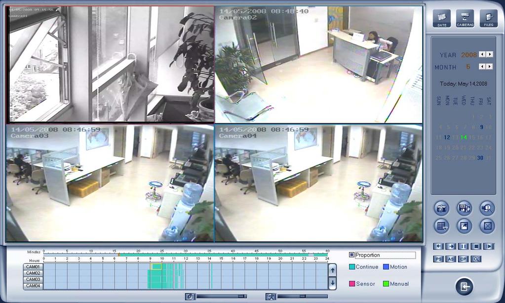
62 4.1 Main interface Chapter4 Playback Click button in main interface to enter playback interface. if your screen resolution is 1024*768,the playback screen could be adjusted by the Proportion as bellow. 62

63 63 DVR Server Manual


64 4.2 Select playback channel Select date Select one window (the 1 st one in default), and then click show the date. button to The blue dates contain recorded data. The green date is the current date. The gray dates signify no data. Only those blue ones can be selected and when they are selected the camera window will appear automatically to show which cameras has record data. Click or to change month and year of search data. You should select the data first,otherwise,you can t entry the all sub-playback interface. It can t select the data in the sub- playback interface Select camera 64

65 After selecting date system will show the camera state of corresponding day, or click button directly to show the cameras state of current day. The number button with navy blue means this channel has record data. By pressing it directly on the numerical panel, DVR system will play back recorded data from the first file Select file After selecting the camera to play user can click the files of this camera. button to show all In default, system will play back video file from the first one. In this screen you can change the file you want to play by clicking it directly. The camera list below the window will show the recorded data of the day you select. Double clicking one hour of that day,system will play back data from the beginning of the hour via the window you select. 65
66 Press or button to see the recorded data of other cameras, Click any minute of that hour, immediately, the system will turn to play back that time via the window you select. The red bar of the minute s list and hour list means the exact time which system is playing back now. Tips: Right click the picture to perform digital zoom function. Different color will show information of all cameras. You can see all kinds of record, their time and length according to recorded data. 4.3 Play file and related operations Press this button to set partition mode of Window, there are 1,4, 9and 16 splits. To reduce the load of CPU and get best effect, you should select the partition mode according to the record channels amount and resolution. There is a referenced configuration sample as below: Computer configuration: CPU: Intel Pentium 4 2.4GHz Motherboard: ECS 848P-A Graphic Card: ATI MB Memory: 512MB HDD: 120G(IDE) Recommended channel configuration for playback: DVR Board Channels Record Resolution Recommended Playback Channels 64 CIF 4 48 CIF 4 40 DCIF 4 CIF 4 32 DCIF 4 CIF 9 24 DCIF 9 CIF 16 4CIF 4 66
67 4CIF 4 D CIF 16 9 Press this button to open all playback windows in sequence according to the order of the cameras. next minute. Press this button to close all playback windows. Previous / Next Minute: press this two buttons to look previous or Next frame: press this button continuously to play video next frame, the speed is determined by the following playing speed adjustment bar. / Play/Pause: This button will alternate between Play and Pause. When it is playing, it will show and press it to stop, and then the button will show. When you select reverse playing, it will show to play by pressing it. Stop: press this button to stop playing. Image zooms out. Press this button, Left-Single-Click an image; quarter of the image will be enlarged. Right-Single-Click the image again, it will resume the normal. and click the left button to clear the voice. Adjust the voice: drag the bar to adjust the voice Adjust playing speed: drag the bar to adjust the playing speed and click the left button to resume normal playing speed. *Note: It is not suggested that multi-channel (more than 10 channels) record or playback coinstantaneous unless your PC has a advanced configuration, because the data throughput of HDD is huge in that case. Multi-channel search in client and server are the same except their paths. In client, they are in local; in remote search, it searches among the record data in server in the local network. 4.4 Capture picture Click capture button to capture a still picture. When one is captured, there will display a dialog to ask for a file name. After your 67

68 confirmation, you will be asked to input the save path. *Note: the size of the image is that of the playing window. 4.5 Create clip file Click button,there are three items to be selected as below Create file clip Press to create file clip. Select channel and save path Select channel and save path of the backup file on the top of interface. File list and attribute Select a file and double-click it to play and its attribute will display below the list, including begin time, end time, file size, resolution, frame rate etc. 68


69 Play control button User can press and drag slider on to control the player time. Beginning and stop position setup After you select a time, press button to set it as the beginning time, and then drag the bar to select another time and press button to set it as the end time. When you finished, the file attribute on the left will show the size of the file to be created. Save file After you set the beginning and end time press button to save the file, and it will ask for the file name named by you. Voice control Click to control voice, press it to clear voice Backup by time: Press to enter backup by time feature. 69

70 Backup Path Select path for the backup file, User can backup record file to CD. Backup Camera Select the backup camera. User can select more than one camera at one time. Select begin time Select end time Select the beginning time and end time of the file to backup. It can backup the data feature and remove file unite function when backup, so that backup procedure is faster. You can check the file s value by pressing total value. button to show its Backup Date Size Show the size of the backup file. If user backup recording file to CD directly, the date size should not more than 650M. NOTE: If user backup recording file to CD directly, the system disk volume s(c volume in general) free space should not less than twice of the backup date size. Because system volume will be used buffer area when burn CD. For example, if the backup date size is 450M,so, the system volume s free space should more than 900M. 70


71 The process of burning CD: 1.Select the CD-ROM as backup path, and select the camera and time. 2.Check the backup file value. 3.Backup the file to the temporary file in the last volume if there have enough free space. Otherwise, write backup file to the last second volume. 4. Write data to buffer. 5. Write CD. 6. Delete buffer and temporary file View Backup file a. Select channel Select channel. b. Save Path Select path of the backup file. c. Select one file from File List and Double-Click it, this file will be played. The united file is named by date + begin time and date + 71

72 end time. d. Capture a picture. e. Burn CD Copy the file player in the Save path. :Add selected file :Delete selected file Burn CD drive Select CD-ROM driver. Volume label Set the CD s label. Total file size Show the size of all files will be burned to CD. or DVD. When you finish your setup, click this button to write file to CD Clean up the data of CD/DVD. Open the CD ROM Close the CD ROM 72


73 It supports DVD or CD disc backup directly, max support 4.3G DVD disc and user can erase DVD-RW disc and write again, all work needn't install third burning software. 4.6 Search captured picture Click to enter the search captured picture window: Select pictures from directory and file list You can select a captured picture from directory list and file list in local disk and the file name will show in the top of the window. 73
74 Note: If you want to save the reworked picture in another file, you can change its name and path here, with BMP or JPG as suffix. Then click the button. Related operations Save the reworked picture. picture disposal. Functional buttons of When the result of disposal is not good click it to the default. Print picture, when the image is wider than 400 pixels, it will be printed smaller. On the other hand, it will be printed bigger. enlarged. When it s bright, with the mouse moving, part of the picture will be 4.7 Fast search Delete current file or delete all files. Click button to show the date: The green date is the current date. The gray dates signify no data. Only those blue and green ones can be selected and when they are selected the camera window will appear automatically to show which cameras has record data. Click or to change month and year of search data. 74


75 4.8 Camera status Click button to show the cameras state. If the number is bright, it means there has record data in this channel Synchronic play time. Click button to synchronize all playback channels Smart search 1. Function introduction: This function allows users to draw a zone on a video image and do a search for any motions, missing objects, or unattended object events occurred in that zone. It can help you find recorded video you are interested. Notice: Smart Search accuracy is decided by sensitivity value in Motion Setup 2. Operation and example Press button, then select a search area, the system will play all motion occurred within this area from previous 3 seconds to next 3 seconds when the motion occurred. Pressing this button again will end smart 75


76 search. E.g.: There is a telephone on the desk (Picture 1). 2.But it disappeared now (Picture 2). 3.If you want to know where the telephone is, you can select this area on the image to do a smart search when playback the video. Note: 1. Press synchronic button while smart search is running, system will end smart search. 2. The sensitivity of the smart search is same as motion detection. If you set a high sensitivity, system will search even that there is no motion in specified area. Contrarily, if you set a low sensitivity, it is possible that system will not search when there is some small range motion in specified area. So you should set the sensitivity according to the surroundings. 4.9 Show files Click button to show all the files of current cameras. *Note: 1.It is not suggested that multi-channel(more than 10 channels) record and playback coinstantaneous unless your PC has a wonderful configuration, because the data throughput of HDD is huge.multi-channel search in client and server are the same except their paths. In client there are local and lan search. In lan search, it searches among the record data in the local network of server. 76

77 4.10 POS Playback Press the button,you will see the interface as below: Show Txt: show the txt on the screen,(if you select txt overlay in the Cam setup,the show txt is invalid. Data :Select the search data. Camera:Select the search camera TXT Filter:Search the content including the word. Eg: 77
78 The word of the TXT.Filter is THANK,then,press the Search,the content display all the Pos messages with the THANK From.. To: Select the begin time and the end time press this button to search the record for the setting setup page. press these button to back or next the display 4.11 ACU Playback Press the button,you will see the interface as below: 78

79 Show Txt: show the txt on the screen,(if you select txt overlay in the Cam setup,the show txt is invalid. Data :Select the search data. Camera:Select the search camera From.. To: Select the begin time and the end time press this button to search the record for the setting setup User Name: Search the ACU record with the name input in the blanks.eg: 79


80 Input the Wang in the User Name,then press search,,the content display all the ACU messages with the user name Wang 4.12 ICON Playback Press the button,you will see the interface as below: Select the cameras 80
81 the end time of the record, Set the begin time and set the time of the one view plays. Eg: as the above image,the time from 9:45 to 12:00, it include 135 minutes between the begin time and the end time,the screen is 4 views, the first view show the 0-10 minutes record,the second view show the mintues record,..,when the 4 views plays endly,it will play the second 40 minutes until the 135 minutes all endly. 81

82 Chapter5 IE client The client user can view video of DVR Server through Internet Explorer, The default web server port is 80; if user changes it to other port, user should add this port number after domain name when visit the video of Server through Internet Explorer. E.g.: Functions of IE Client 1. Video display and video storage; 2. Audio input; 3. Searching and playback video image locally or remotely; 4. Control PTZ and speed demo remotely; 5.2 Main interface When you connect foreside server successfully, you should input valid User ID and password in left up of the interface to acquire rights to play video and other operations. 82
83 5.2.1 Connection operations Press will connect the DVR Server s camera video from and press will disconnect all connections. Select the Main Stream or Sub Stream for current cameras Server s channel is more than channels that you selected partition mode, you can use button to display DVR Server s video in sequence. Pressing button will switch full screen mode and Right-Single-Click image can back to normal mode Connection/Record status This icon indicates the current connection and their record status: Gray: Not connected; Navy blue: Connected with no recording; Green: Connected with recording. You can change the record status by pressing corresponding number button or change status of all connections at the same time by pressing button Partition mode You can set the partition mode by pressing corresponding button on the right of main interface. It has follow partition modes: 1partition mode; 6partition mode; 10partition mode; 4partition mode; 9partition mode; 16partition mode PTZ Control 83

84 Most functions of PTZ control are same as PTZ Control panel in DVR Server Quit program Press button to shut down the IE Client. 5.3 Local search Press button to enter local search: Playing operation area Display setup and data information Display setup and data information 84
85 In this area, you can select display partition mode, date, video channel and its video file named according to time Playing operation area In this area, you can operate video playing: Video-playing time adjustment Press and drag slider bar to adjust video-playing time Information display panel Display current window name, camera name and record data information. Playing-control buttons : Play, Pause, Stop. Single frame play : Previous frame, next frame Playing speed control Slowly play Fleetly play 5.4 Remote search Most functions and operations of Remote search are same as playback; different feature is that remote search added download feature 85


86 When you playback remotely, you click button, system will save video of current channel you selected. After finishing it, system will inform the save path Fast download record data In the playback mode, select one camera that has record data, open file list panel, select one record data file, and click button, the selected data file will download fast. NOTE: When user use IE client to visit DVR server, If connect successfully, there will appear four partition blue window. If connect unsuccessfully, the reasons possibly are: 1. The Web server port has been used by other programs. 2. Your computer didn t download the player plug normally. The reason may be the jurisdiction of your computer is too high, or your computer has plug filter. 86
87 Chapter6 Mobile Client 6.1 Recommended Mobile Phone Requirements 1 Before you run Mobile Client, please check if your mobile phone supports JAVA and comply with following applicable standards: CLDC version: CLDC-1.0 MIDP version: MIDP Your mobile telephone should have GPRS or CDMA to transport data. 3 Set Internet as the access point of your phone call. 4 Select Enable to allow the PDA to connect With DVR server in the network setup of the DVR system. 5 To use PDA connection normally, the DVR board should support dual compression and user must open sub channel compress in camera setup. User should select CIF or QCIF but not same as recording for remote Remote Image size. Note: GPRS is charged by data flow, so shut down the MobileDVR application if you do not need to view cameras. 6.2 Download software You have following methods to download our mobile client software: 1) Download through wireless technology (in Wireless LAN) such as Blue tooth, infrared. 2) Copy mobile client software to phone directly through data cable. 3) Download mobile client software through OTA (in WAN), it will describe as follow: Enter in the address bar of the mobile telephone internet explorer to download the setup package of the Mobile Client. Note: IP: the IP address of the DVR server. PORT: the Port of the IE client of the DVR server. When you download mobile client software on WAN, you must be sure that your mobile phone connect with Internet correctly. 87
 or use the application supplied by the manufacture of your smart phone to install mobile client. 6.3.")
88 6.3 Install and connect Installation You can install the mobile client as install java games in your smart phone, install mobile client in your smart phone directly (downloaded the program in WAN or LAN) or use the application supplied by the manufacture of your smart phone to install mobile client Connection After you installed mobile client in your smart phone, you should be sure that your smart phone connect with Internet correctly. Currently, mobile providers support WAP and WEB access point, mobile client must use Internet as access point (AP) to access DVR Server remotely. 6.4 Login Interface After you downloaded and installed the MobileDvr software, you can run it on your mobile phone to enter the login interface. Addr Fill the IP address or domain name of the DVR server. Port Fill the port through which connects to DVR Server. User / Pass Fill the valid user with its password to visit server from MobileDvr. And the server has enabled rights management, login user ID and password from client will be checked. If the user has no right to visit that camera, the connection will be cut down automatically. 88


89 Press Login button to connect the DVR server. 6.5 Camera List The MobileDvr will enter the Camera List after you connect the DVR server successfully. Select the Camera you want to browse and press the preview button to get the image from the server. 89


90 6.6 PTZ control Press the Options button and select the PTZ button to enter the PTZ control interface. Orientation control : Select the button and press OK,it will change into. After that, by pressing and holding the up, down, right and left buttons, the PTZ camera will move up, down, right and left. Note: Please try 5 button on your phone if pressing OK does not work.. Zoom + / Zoom : Control the zoom function of the PTZ camera. Focus+/ Focus : Overrides the auto-focus setup of the PTZ camera, adjust focus the image. Iris on/off : Overrides the PTZ cameras auto-iris and brighten 90
91 or darken the image. 91
 Play in fast speed (in the status of instant playback and review playback) Down(in the status of preview for PTZ control) Play in slow speed")
92 Chapter7 Appendixes 7.1 Appendix A: Fast key reference Please refer to shortcuts keyboard setup This color key denotes PTZ control. PTZ control: This color key is other function control. Key Function Up(in the status of preview for PTZ control) Play in fast speed (in the status of instant playback and review playback) Down(in the status of preview for PTZ control) Play in slow speed (in the status of instant playback and review playback) Left(in the status of preview for PTZ control) Play last frame(when pause in the status of instant playback) Play again(in play condition of review playback) Play last frame(in pause condition of review playback) Right(in the status of preview for PTZ control) Play next frame(in the status of instant playback) 92
93 Play in normal speed(in play condition of review playback) Play next frame((in pause condition of review playback) Home End Insert Delete C Num0-9G Zoom- Zoom+ Focus- Focus+ Presets Control OperationCall preset Enter C Num0-9 Presets Control Operation Other controls: Key F1 Tab Page Down Page UP F9 F11 F12 Ctrl + 0 Ctrl Function System Help Switch the camera channel Next screen Previous screen All cameras recording 30 Sec emergency Zoom in/out the single camera view Switch to Full screen mode (Equivalent to pressing space key except Instant Playback mode) Enter playback Instant playback minutes Shift Select screen partition 1,4,9,16,25,36,49,64 WIN+ Z Minimize the Main System window 7.2 Appendix B: Audio preview First, connect the card use the cable, as follows: 93


94 NOTE: Sometimes there is no preview sound, Solution: double click the volume control of in the taskbar, open the properties dialog box, and check AUX control. 7.3 Appendix C: Update drivers of compressed card If you first install the card or upgrade the DVR software, you should install or update the card driver. The steps are as follows: 1) Find the driver folder, and run driver Install program. 94
 Click Install or Update Driver button, a")


95 2) A dialog will show on the screen. 3) Click Install or Update Driver button, a prompt UI will inquire you, click yes, the program will continue the installation. 4) If the driver installed successfully, the program will show you a prompt, click OK, the install driver program finished. 95

96 7.3 Appendix D: How to use Copy File folder. In installation CD, there is a file named CopyFile If you want to replace some files in installation directory, you can copy new files into CopyFile, when you finished the installation, the new files will replaced the old files. If you want to replace some files in sub directory of installation directory, you can create the same directory in CopyFile folder with the installation directory. Thus, when you finished the installation, the all files which in CopyFile will replace the old files. Note: If you replace the image, the new image s size and name should be same with old image. 7.4 Appendix E: Explanation about NV series DVR board. This DVR System manual is suitable for all NV series DVR board (NV400XHC,NV400XC,NV400XCE,NV4016HCS) NV400XHC: support double encoding, when image size was selected D1 Auto F,NV400XHC card only single encoding. NV4016HCS: Single encoding. NV400XC:Single encoding. NV400XCE:Support double encoding. 96
KIKO Consulting DVR Server USER S Manual
 KIKO Consulting DVR Server USER S Manual Contents Chapter1 Start up and Main Interface 8 1.1 Start up 8 1.2 Main Interface 9 1.2.1 Show tips 9 1.2.2 Screen menu 9 1.2.3 Interface description 13 1.2.4 System
ipoint Ultra v5.17 Hybrid Server USER MANUAL
 ipoint Ultra v5.17 Hybrid Server USER MANUAL 1 of 63 Table of Contents Introduction:... 4 System Features:... 4 1. Start Up and Main Interface... 5 1.1. Start Up... 5 1.2 Main Interface... 6 1.2.1 Show
VR Enterprise DVR System
 VR Enterprise DVR System DVR Server (ver. 6.05) User Manual I II DVR Server Manual ver.6.05/rel.120909 Contents Chapter1 Start up and Main Interface 3 1.1 Installing 3 1.2 Disk management 3 1.3 Start up
LV Server Lite. Lanvision Lite. User s Guide
 Lanvision Lite DVR system User s Guide I Contents Chapter1 Start up and Main Interface...11 1.1 Preparation & Uninstallation... 11 1.1.1 Installation... 11 1.1.2 Uninstallation... 11 1.2 Disk management...
ipoint Ultra v6.32 Client User Manual ipoint Ultra v6.32 Client USER MANUAL
 ipoint Ultra v6.32 Client User Manual ipoint Ultra v6.32 Client USER MANUAL I ipoint Ultra v6.32 Client User Manual Content Chapter 1 Start up and Main interface... 8 1.1 Disk management... 8 1.2 Start
NVR Client system. User Guide
 NVR Client system User Guide Content Chapter1 Start up and Main interface 2 1.1 Start up 2 1.2 Main interface 6 1.2.1 Interface description 6 1.2.2 Select playback channel 8 1.3 System Menu 11 1.3.1 Remote
Netvision DVR system
 Netvision DVR system USER S GUIDE China Chongqing Netvision Technology Co., Ltd TEL: (86)23 68697255 FAX :(86)23 68639816 www.jstdvr.com www.netvisiondvr.com I Contents Chapter1 Start up and Main Interface...
Hybrid NDVR system USER S GUIDE
 Hybrid NDVR system USER S GUIDE Contents Chapter1 Start up and Main Interface... 10 1.1 Preparation & Uninstallation... 10 1.1.1 Preparation... 10 1.1.2 Uninstallation... 11 1.2 Disk Management... 12 1.2.1
LV Client Lite. Lanvision Lite. User s Guide
 Lanvision Lite Client System User s Guide I Content Chapter1 Start up and Main interface...11 1.1 Preparation & Uninstallation... 11 1.1.1 Preparation... 11 1.1.2 Uninstallation... 11 1.2 Start up... 12
IP Camera. USER S Manual
 IP Camera USER S Manual China Chongqing NetVision Technology Co., Ltd TEL: (86)23 68697255 FAX:(86)23 68639816 www.jstdvr.com http://www.netvisiondvr.com/ CONTENTS Chapter1 Configuration & Connection...
ipoint NVR Client System
 ipoint NVR Client System USER S GUIDE 4973 Rivers Avenue Building 300 North Charleston, SC 29406 Phone 843-745-0045 or 888-885-5577 www.tscharleston.com Table of Contents ipoint NVR User Manual Introduction...
Control center. USER S Manual
 Control center USER S Manual Contents Chapter1 System introduction... 1 1.1 System Frame and work mode... 1 1.2 Control center... 3 1.3 Video site... 3 1.4 Client... 3 1.5 E-Map... 4 1.6 Send video image
Hybrid NDVR system USER S GUIDE. China Chongqing Netvision Technology Co., Ltd TEL: (86) FAX :(86)
 FAX :(86)") Hybrid NDVR system USER S GUIDE China Chongqing Netvision Technology Co., Ltd TEL: (86)23 68697255 FAX :(86)23 68639816 www.jstdvr.com www.netvisiondvr.com I Contents Chapter1 Start up and Main Interface...
Hybrid NDVR system USER S GUIDE China Chongqing Netvision Technology Co., Ltd TEL: (86)23 68697255 FAX :(86)23 68639816 www.jstdvr.com www.netvisiondvr.com I Contents Chapter1 Start up and Main Interface...
CMS Client Manual. CMS Client System. User s Guide
 CMS Client System User s Guide I Content Chapter1 Start up and Main Interface... 9 1.1 Preparation & Uninstallation... 9 1.1.1 Preparation... 9 1.1.2 Uninstallation... 11 1.2 Start up... 12 1.3 Main interface...
User s Manual of DVR ULTIMAX. Remote Client Software V wersja 2.40
 User s Manual of DVR ULTIMAX Remote Client Software V 4.0.1 ULTIMAX-304 ULTIMAX-308 ULTIMAX-316 ULTIMAX-504 ULTIMAX-508 ULTIMAX-516 ULTIMAX-704 ULTIMAX-708 ULTIMAX-716 wersja 2.40 Index 1 Software Install,
Client Software-4000(V ) User Manual
 User Manual") Client Software-4000(V2.00.02) User Manual Index Chapter 1 Welcome to Client Software-4000 (V2.0)... 1 1.1 Overview... 1 1.2 Computer Disposition Request... 1 1.3 Convention... 1 Chapter 2 Install & Uninstall...
Client Software-4000(V2.00.02) User Manual Index Chapter 1 Welcome to Client Software-4000 (V2.0)... 1 1.1 Overview... 1 1.2 Computer Disposition Request... 1 1.3 Convention... 1 Chapter 2 Install & Uninstall...
NVMS1000. User Manual
 NVMS1000 User Manual Contents 1 Software Introduction... 1 1.1 Summary... 1 1.2 Operation Environment... 1 1.3 Install and Uninstall... 2 1.3.1 Install the Software... 2 1.3.2 Uninstall the Software...
Unisight DVR System. Unisight DVR Manual. Ver rev1.3.4
 Unisight DVR Manual Ver2.7.1027 rev1.3.4 1 Table of Contents System Requirements.8 Unisight DVR Server.. 8 Server Hardware Requirements...8 Server Software Requirements 8 Client Hardware Requirements...
NVMS User Manual
 NVMS-1000 User Manual Contents 1 Software Introduction...1 1.1 Summary... 1 1.2 Operation Environment... 1 1.3 Install and Uninstall... 2 1.3.1 Install the Software... 2 1.3.2 Uninstall the Software...
CMS Client System. User s Guide
 CMS Client System User s Guide TEL: (86)23 68697255 FAX :( 86)23 68639816 www.jstdvr.com www.netvisiondvr.com 1 Content Chapter1 Startup and Main Interface... 8 1.1 Introduction... 8 1.1.1 Preparation...8
VMS-A1 Client Software. User Manual
 VMS-A1 Client Software User Manual Contents Contents... 2 Chapter1. Overview... 4 1.1 Description... 4 1.2 Features & Functions... 4 Chapter2. Update Info... 6 Chapter3. Starting VMS-A1... 7 3.1 Installing
NVMS User Manual
 NVMS-1000 User Manual Contents 1 Software Introduction...1 1.1 Summary... 1 1.2 Operation Environment... 1 1.3 Install and Uninstall... 2 1.3.1 Install the Software... 2 1.3.2 Uninstall the Software...
NVMS1000. User Manual
 NVMS1000 User Manual Contents 1 Software Introduction... 1 1.1 Summary... 1 1.2 Operation Environment... 1 1.3 Install and Uninstall... 2 1.3.1 Install the Software... 2 1.3.2 Uninstall the Software...
USER MANUAL. Mac Version
 USER MANUAL Mac Version Contents 1 Software Introduction... 1 1.1 Summary... 1 1.2 Install and Uninstall... 1 1.2.1 Install the Software... 1 2 Login Software... 3 2.1 Login... 3 2.2 Control Panel Instruction...
Video Surveillance Management Software NVClient V5 User Manual
 Video Surveillance Management Software NVClient V5 User Manual Version: V5.0 Update Date: 2013-12-12 Welcome Thanks for using the Company's digital video surveillance management software. Please read this
NVMS User Manual. Version 2.1.0
 NVMS-1000 User Manual Version 2.1.0 Contents 1 Software Introduction... 1 1.1 Summary... 1 1.2 Operation Environment... 1 1.3 Install and Uninstall... 2 1.3.1 Install the Software... 2 1.3.2 Uninstall
errors, or places that do not match the product. If you have any unsolved please contact our technical support department.
 - 0 - Statement: This manual may contain several technical inaccuracies or typographical errors, or places that do not match the product. If you have any unsolved problems in the process of using product
HIP2P Network Video Camera Client Terminal User Manual
 HIP2P Network Video Camera Client Terminal User Manual Document version:5.1 Page 1 of 34 } Preface Thank you for using our company's products. The network video camera client terminal is used to implement
NVMS-7000 Client Software User Manual Version 1.03
 NVMS-7000 Client Software User Manual Version 1.03 Contents Chapter 1. Overview... 3 1.1 Description... 3 1.2 Running Environment... 3 Chapter 2. Starting NVMS-7000... 4 2.1 User Registration... 4 2.2
SunEyes V Series IP Camera P2P CMS user manual
 SunEyes V Series IP Camera P2P CMS user manual Version: 2.0 Date: July. 2015 This document is applicable to all series devices in our company. Page 1 ON page 40 foreword The HiP2P client of IP Camera is
PROFESSIONAL PROTECTION INCORPORATED
 PROFESSIONAL PROTECTION INCORPORATED EAGLE EYE DIGITAL VIDEO RECORDING AND SURVEILLANCE SYSTEMS 1101 Tyvola Road Suite 202 Charlotte North Carolina 28217-3515 Business: (704) 523-1660 Facsimile: (704)
CMS USER S MANUAL VER:
 CMS USER S MANUAL VER: 1.0 2009-1-6 1 INDEX INDEX... 2 Preface... 3 1. Introduction... 4 2. Install and uninstall CMS... 4 2.1 System requirement... 4 2.2 Computer Hardware Requirements... 5 2.3 Process
W Box VMS BOX T E C H N O L O G I E S.
 W Box VMS BOX T E C H N O L O G I E S www.wboxtech.eu Contents Contents... 1 Overview... 3 1.1 Description... 3 1.2 Running Environment... 3 1.3 Function Modules... 3 Live view... 6 2.1 User Registration
ivms-4000(v2.03) User Manual
 User Manual") ivms-4000(v2.03) User Manual Table of Contents ivms-4000(v2.03)...2 User Manual...2 Table of Contents...1 Chapter 1 Welcome to ivms-4000 (V2.03)...4 1.1 Overview...4 1.2 Computer Disposition Request...4
ivms-4000(v2.03) User Manual Table of Contents ivms-4000(v2.03)...2 User Manual...2 Table of Contents...1 Chapter 1 Welcome to ivms-4000 (V2.03)...4 1.1 Overview...4 1.2 Computer Disposition Request...4
Video Management Software
 Video Management Software User Manual Web: europesecurity.eu Mail: info@europesecurity.eu Tel.: 0541 352 952 User s Manual 2 Contents CHAPTER : XMS CENTRAL USER MANUAL 1 PC REQUIREMENT 3 2 INSTALL 3 3
Quick Operation Guide of ivms-4200
 Quick Operation Guide of ivms-4200 V1.02 2012-02-22 Description ivms-4200 is a video management software using a distributed structure to manage all the connectable devices. It can manage the NVR, DVR,
Manual Version: V1.15. Video Management Software Guard Station User Manual
 Manual Version: V1.15 Video Management Software Guard Station User Manual Thank you for purchasing our product. If there are any questions, or requests, please do not hesitate to contact the dealer. Disclaimer
Central Management Software for NVR-915 / NVR-1615 CV5-M256
 Central Management Software for NVR-915 / NVR-1615 Table of Contents Chapter 1. Main Console... 4 1.1 Tool Bar... 4 1.2 NVR List... 5 1.3 Division List... 7 1.4 Group List... 9 1.5 PTZ Panel...11 1.6 Operation
Quick Start Guide 4/8/16-Ch DVR
 Quick Start Guide 4/8/16-Ch DVR 1 1. Install Hard Drive &DVD Writer 1.1Install Hard Drive Notice: 1. Support two SATA hard drives. Please use the hard drive the manufacturers recommend specially for security
JVS-D7216 Standalone DVR User Manual
 Menu JVS-D7216 Standalone DVR User Manual JVS-D7216 Standalone DVR Instructions 1. Introduction..4 1.1 Product Description...4 1.2 Features..4 1.3 Specifications...4 2. Product Features....6 2.1 Panel
VMS2.0 Client Software. User Manual
 VMS2.0 Client Software User Manual Chapter 1 Contents Brief Introduction...1 1.1 Description... 1 1.2 Running Environment...1 Chapter 2 Installation... 2 Chapter 3 Live View... 4 3.1 User Login...4 3.2
CMS USER S MANUAL VER:
 CMS USER S MANUAL VER: 1.0 2009-1-6 1 INDEX INDEX... 2 Preface... 3 1. Introduction... 4 2. Install and uninstall CMS... 4 2.1 System requirement... 4 2.2 Computer Hardware Requirements... 5 2.3 Process
SKY l SYS DVR USER S MANUAL TABLE OF CONTENTS. Skydreamers Systems DVR Page 1
 TABLE OF CONTENTS Main System Application (Control) SERVER Startup Screen 6 Login/Logout/Shutdown 7 Control Screen 7 Setup 7 System Power Management 8 Auto Switching Interval 8 E-map 8 TV-Out 8 On-screen
Unisight DVR System. Unisight DVR Manual. Version Rev 1.0
 Unisight DVR Manual Version 1.8.0131 Rev 1.0 1 Table of Contents System Requirements...5 Server Hardware Requirements...5 Server Software Requirements...5 Client Hardware Requirements...5 Client Software
IP Solution Intelligent Surveillance Solution
 IP Solution Intelligent Surveillance Solution user s manual Table of Contents TABLE OF CONTENTS TABLE OF CONTENTS...1 SYSTEM REQUIREMENT...5 INSTALLATION...6 QUICK START...10 1. MAIN CONSOLE...14 1.1 Start...16
SecuGuard. Basic 5.0. Version: xxx
 SecuGuard Basic 5.0 Ł` ˆª Ø Version: 5.0.2.xxx SecuGuard Basic ` Ø ˆ ˆ...6 ˆ Ø...7 Ł ˆ Ø»ˆÆ ˆ`... 7 ˆŁ` ˆ Ø»ˆÆ ˆ`... 7 Ø Æ Ł...10 Ø IP Camera(s)... 10 Ł` IP Camera(s)... 10 ˆ Ø Ł ˆ ˆ :... 14 Playback:...
Quick Start Guide 4/8/16/24-Ch DVR
 Quick Start Guide 4/8/16/24-Ch DVR 1.1 Install Hard Drive 4/8/16/24-CH DVR Quick Start Guide Notice: 1.4/3/16-ch DVR supports one SATA hard drive. 24-ch DVR supports three SATA hard drives. Please use
Before Setting. GMS is an integrated security management system that provides a useful solution for central monitoring station operation.
 GMS MANUAL Before Setting What What is is GMS? GMS? GMS is an integrated security management system that provides a useful solution for central monitoring station operation. Minimum Minimum System System
SecuGuard. Basic 5.0. User s manual. Dec Version: 5.0.x
 SecuGuard Basic 5.0 User s manual Dec. 2009 Version: 5.0.x SecuGuard Basic System Requirement...5 Installation...6 Before Installing the Software... 6 Starting the Installation... 6 Quick Start...9 Install
Vegas Valley Video Systems. Vegas Valley DVR Manual TZHC Series Server
 Vegas Valley DVR Manual TZHC Series Server 1 Table of Contents Initial Startup...4 Initial Setup...4 Live Preview Mode...5 DVR Information Window...6 Camera Status LEDs...6 Channel Grid...7 Grid Layout
DVR System. NW9400 Manual Version Rev 1.2
 NW9400 Manual Version 2.8.0131 Rev 1.2 1 Table of Contents DVR System System Requirements...5 Server Hardware Requirements...5 Server Software Requirements...5 Client Hardware Requirements...5 Client Software
Quick Start Guide 4/8/16-Ch DVR
 Quick Start Guide 4/8/16-Ch DVR 1 1. Install Hard Drive &DVD Writer 1.1Install Hard Drive Notice: 1.This series support one SATA hard drive. Please use the hard drive the manufacturers recommend specially
IMS200 SURVEILLANCE SYSTEM USER MANUAL
 IMS200 SURVEILLANCE SYSTEM USER MANUAL 1 PRECAUTIONS The contents of this manual may change due to product upgrades or other reasons. We have the right to make changes of the contents without notice. This
User Manual of Client Software for Embedded DVRDVS (Version 1.4)
") User Manual of Client Software for Embedded DVRDVS (Version 1.4) 1 Index Version Description...3 Chapter 1 Client Software Installation...6 1.1 Notice...6 1.2 Installation...7 Chapter 2 Client Software
User Manual of Client Software for Embedded DVRDVS (Version 1.4) 1 Index Version Description...3 Chapter 1 Client Software Installation...6 1.1 Notice...6 1.2 Installation...7 Chapter 2 Client Software
Quick Start Guide 4/8/16-CH DVR.
 Quick Start Guide 4/8/16-CH DVR 1. Install Hard Drive &DVD Writer 1.1 Install Hard Drive Notice: 1. Support two SATA hard drives. Please use the hard drive the manufacturers recommend specially for security
Quick Start Guide 4/8-CH DVR
 Quick Start Guide 4/8-CH DVR 1 1. Install Hard Drive &DVD Writer 1.1 Install Hard Drive Notice: 1. this series support one SATA hard drives. Please use the hard drive the manufacturers recommend specially
NVMS-5000 NVMS User Manual
 NVMS-5000 NVMS-5000 User Manual NVMS-5000 User Manual Contents 1 Introduction... 4 1.1 NVMS-5000 Brief Introduction... 4 1.1.1 Summerization... 4 1.1.2 Software Architecture... 4 1.2 System Components...
SURVEILLANCE KIT USER MANUAL. All in One Series
 SURVEILLANCE KIT USER MANUAL All in One Series Contents Part one Basic Operation 1 1. Basic Installation 1 1. Hard Disk Installation 1 2. Mouse Connection 1 2. Starting 1 3. Turn Off 1 4. Login 2 5. Preview
Quick Reference Guide. For IL6000HB Series NetDVR
 Quick Reference Guide For IL6000HB Series NetDVR Directory 1. Features and Specifications.1 2. Physical Interface 2 2.1 Front Panel and Interior of Product 2 2.2 Rear Panel of Product..3 3. Software Main
Manual Version: V1.01. ISS Manager Video Management Software User Manual
 Manual Version: V1.01 ISS Manager Video Management Software User Manual Notice The information in this manual is subject to change without notice. Every effort has been made in the preparation of this
User Manual. Contents 1 WELCOME Features Installation Requirements Software Installation Software Operation...
 CMS User Manual Contents 1 WELCOME... 3 1.1Features... 3 1.2Installation Requirements... 3 1.3 Software Installation...4 2 Software Operation... 5 2.1 Menu bar... 6 2.2 Camera list tree... 7 2.3 Camera
NetClient software user manual
 NetClient software user manual 1-1. General information Net Client is an application which provides users not only viewing and controling remote DVRs, but also receiving realtime event data or alarm signals
User Manual. Central Monitoring Software for TER-series recorders. CenPro
 EN User Manual Central Monitoring Software for TER-series recorders CenPro Contents CENPRO USER MANUAL 1 PC REQUIREMENT 3 2 INSTALL 3 3 UNINSTALL 5 4 BASIC OPERATION 7 4.1 Log In 7 4.2 Screen Layout 8
AVerMedia. CM3000 Central Management System. User Manual
 AVerMedia CM3000 Central Management System User Manual DISCLAIMER No warranty or representation, either expressed or implied, is made with respect to the contents of this documentation, its quality, performance,
DS-1100KI Network Keyboard User Manual V 2.1.0
 DS-1100KI Network Keyboard User Manual V 2.1.0 (V2.0) Preventive and Cautionary Tips Before connecting and operating your keyboard, please be advised of the following tips: Ensure unit is placed in a well-ventilated,
Centralized Monitoring Management Platform. Manual
 Centralized Monitoring Management Platform Manual 3 Contents 1. Products... 5 1.1. Summary... 5 1.2. Application Environment... 5 1.3. Install and uninstall... 6 2. Centralized Monitoring Management Platform
Digital Video Surveillance Center Management Software
 Digital Video Surveillance Center Management Software NVClient User Manual Revision: V3.2 Updated: 12-2011 Contents Chapter I General...- 3-1.1 INTRODUCTION... - 3-1.2 MAIN FUNCTIONS... - 3 - Chapter II
IP WEB User Manual V2.0
 IP WEB User Manual V2.0 Please read carefully before installing or contacting your supplier. The information contained at the time of printing is correct, but is subject to change without notice. This
The Intelligent Surveillance Solution. User manual
 The Intelligent Surveillance Solution User manual CONTENTS 1.1 System Requirement... 1 1.2 Installation... 1 1.3 Quick Start... 5 2.1 Start Menu... 10 2.2 Information Window:... 12 2.3 PTZ Config:... 12
Chapter 3 Operating instructions
 Chapter 3 Operating instructions Summary This chapter describes the how to control and navigate through the TVR 30 s menus and options. Content Control interfaces 10 Controlling the TVR 30 10 Front panel
Lorex Client 7.0 & Lorex Message Master
 Lorex Client 7.0 & Lorex Message Master Software Manual English Version 1.0 MODELS: L19WD Series www.lorexcctv.com Includes L19WD800 & L19WD1600 Copyright 2008 Lorex Technology Inc. Table of Contents Table
Enterprise Pro Surveillance System User s Manual
 Enterprise Pro Surveillance System User s Manual 1 Table of Contents 1 FEATURES... 6 2 INSTALLATION... 8 2.1 Environment...8 2.2 Installation...8 2.3 Un-installation...10 3 NAVIGATION AND CONTROLS OF THE
User`s Manual. CMS Pro. Professional Central Monitoring Software. Full-featured Enterprise Class Surveillance Solution
 Professional Central Monitoring Software CMS Pro Full-featured Enterprise Class Surveillance Solution User`s Manual This document contains preliminary information and is subject to change without notice.
Quick Start Guide (V1.03) UD.6L0201B1064A01
 UD.6L0201B1064A01") ivms-4200 PCNVR Quick Start Guide (V1.03) UD.6L0201B1064A01 Thank you for purchasing our product. If there is any question or request, please do not hesitate to contact the dealer. This manual applies
ivms-4200 PCNVR Quick Start Guide (V1.03) UD.6L0201B1064A01 Thank you for purchasing our product. If there is any question or request, please do not hesitate to contact the dealer. This manual applies
Network Video Recorder Quick Operation Guide
 Network Video Recorder Quick Operation Guide UD.6L0202B1057A01 Thank you for purchasing our product. If there is any question or request, please do not hesitate to contact dealer. This manual is applicable
Outdoor IPC Web Operation Manual Version1.0
 Outdoor IPC Web Operation Manual Version1.0 1 Table of Contents 1 Network Connection...4 2 Main Interface Introduction...5 2.1 Log in...5 2.2 Monitor Channel Menu Tree...8 2.3 System Menu...10 2.4 Monitor
DVR Server Users Manual
 DVR Server Users Manual System Guide... 4 Precaution in Use... 4 Product Guide... 4 Live View... 5 Server Login... 7 Power Off... 7 On-Screen Display (OSD)... 8 View Screen... 8 Digital Zoom... 9 Video
H.264 Network DVR. Quick Start
 341Z H.264 Network DVR Quick Start GUI Display with USB Mouse Control Please read instructions thoroughly before operation and retain it for future reference. For the actual display & operation, please
Network Transmission System
 Network Transmission System Quick Operation Guide Quick Operation Guide of Network Transmission System UD.6L0202B1058A02 Thank you for purchasing our product. If there is any question or request, please
PTZ FUNCTION Presets. 13 Pattern Tracking. 14 Group Run SEARCH & PLAYBACK 17 EMAP. 18 CLIENT SETUP 19 DVR(s). 20 Groups.
. 20 Groups.") 1 REMOTE VIEW 3 Client Login. 5 DVR Connection. 6 Remote Client OSD 7 View Screen 7 Digital Zoom 8 Video Event Log. 8 Image Control. 9 Date & Time 9 Screen Capture.. 10 Forced Recording... 10 Sensors 11
1 REMOTE VIEW 3 Client Login. 5 DVR Connection. 6 Remote Client OSD 7 View Screen 7 Digital Zoom 8 Video Event Log. 8 Image Control. 9 Date & Time 9 Screen Capture.. 10 Forced Recording... 10 Sensors 11
user manual Version /1
 user manual Version 3.1.0.6 2018/1 1 CATALOGUE CHAPTER 1 SOFTWARE INTRODUCTION... 3 1.1 SUMMARY... 错误! 未定义书签 1.2 FEATURES... 错误! 未定义书签 CHAPTER 2 INSTALLATION INSTRUCTION... 6 2.1ENIVRONMENT REQUEST OF
DCMS. User Manual. Version V1.0
 DCMS User Manual Version V1.0 About This Document About This Document About This User Manual Please note the following points before using this user manual: This user manual is intended for persons who
SAFEGUARD CONTENTS. Digital Video Recorder. Version 1.3. Page. DVR Server S A F E G U A R D
 S A F E G U A R D SAFEGUARD Digital Video Recorder Version 1.3 CONTENTS Chapter 1 Chapter 2 Chapter 3 3.1 3.2 3.3 3.4 3.5 3.6 3.7 3.8 3.9 Chapter 4 4.1 4.2 Remote Client Chapter 5 Chapter 6 Chapter 7 7.1
K6 Series IP Camera Web Operation Manual
 K6 Series IP Camera Web Operation Manual Version1.3 1 Table of Contents 1 Network Connection...4 2 Main Interface Introduction...5 2.1 Log in...5 2.2 Monitor Channel Menu Tree...7 2.3 System Menu...10
E-Series Management Software User s Manual
 E-Series Management Software User s Manual Version 1.12.1 Table of Contents 1 OVERVIEW AND ENVIRONMENT... 1 1.1 Overview... 1 1.2 Performance... 1 1.3 Environments... 1 2 INSTALLATION AND UPGRADE... 2
PIVOT CMS CLIENT SOFTWARE USER MANUAL
 PIVOT CMS CLIENT SOFTWARE USER MANUAL 1 CMS USER GUIDE 1.1 PC REQUIREMENT Recommended PC Requirement OS CPU VGA RAM HDD Graphics Card OS CPU VGA RAM HDD Windows Vista, 7 or higher Intel Core2Quad Q9400
E-Vista Digital Surveillance System 300 / 500 Series. User s Operation Manual Copyright By Shaoming Technology
 E-Vista Digital Surveillance System 300 / 500 Series User s Operation Manual 2004 Copyright By Shaoming Technology 1 Contents Copyright Notice... Trademarks.. Special Notice...... Warning... Checking List..
User Manual. 4 Channel 960H High Performance Standalone DVR with HDMI 1080p Output. Model: D4960H-H-BK
 Model: D4960H-H-BK 4 Channel 960H High Performance Standalone DVR with HDMI 1080p Output User Manual 8805 Jones. Rd Ste C104, Houston Texas 77065 * 1-888-861-7351 * www.zuummedia.com Statement: This manual
TruVision Recorder Operator Guide
 TruVision Recorder Operator Guide Live view In the viewer you can see displayed on the live image the current date and time, camera name, and whether a recording is in progress. Information on the system
Network Video Monitor Software
 Network Video Monitor Software V2.0.0.7 Operation menu 1 www.opax.com Chapter 1 Product Overview 1.1 Performance instruction Network video monitoring software is a centralized management software for I8
Digital Video Recorder User Manual. DVR User Manual. For H channel/ 8-channel/16-channel Digital Video Recorder All rights reserved
 DVR User Manual For H.264-4-channel/ 8-channel/16-channel Digital Video Recorder All rights reserved i CAUTION ii Please read this user manual carefully to ensure that you can use the device correctly
Viewgate. DVR Software
 Viewgate DVR Software Table of Contents 5. DVR Software 1 5-1. DVR Setup 1 5-1-1. Disk Tool 2 5-1-2. System Setup 4 5-1-3. Camera Setup 7 5-1-3-1. General Tab 7 5-1-3-2. Schedule Tab 10 5-1-3-3. Color
NVR&IPCAM USER MANUAL V1.0 (USER MANUAL) V1.0. Thanks for choosing our products, please read this manual carefully before use!
 V1.0. Thanks for choosing our products, please read this manual carefully before use!") NVR&IPCAM (USER MANUAL) V1.0 Thanks for choosing our products, please read this manual carefully before use! NOTICE Installation condition 1) In order to ensure your rights, please read this manual carefully
NVR&IPCAM (USER MANUAL) V1.0 Thanks for choosing our products, please read this manual carefully before use! NOTICE Installation condition 1) In order to ensure your rights, please read this manual carefully
H.264 Network DVR. Quick Start
 H.264 Network DVR Quick Start GUI Display with USB Mouse Control Please read instructions thoroughly before operation and retain it for future reference. For the actual display & operation, please refer
NVR some functions manual
 NVR some functions manual 1. Move image to centre... 2 2. Time modify... 2 3. Camera title modify... 3 4. Mask area setup... 4 5. Record before alarm and record after alarm... 5 6. Record setup... 5 7.
CCTV42 System2 DVR Quick Start Guide 4/8/16-Ch DVR
 CCTV42 System2 DVR Quick Start Guide 4/8/16-Ch DVR If you have purchased a DVR / Hard drive package from us then we will have already installed the hard drive(s) and configured the basic settings on your
RX Series. Video Recording Server. Quick Start Guide. RX324v3 / RX328v3 / RX3216v3 RX364v3 / RX368v3 / RX3616v3. Version 1.04
 RX Series Video Recording Server RX324v3 / RX328v3 / RX3216v3 RX364v3 / RX368v3 / RX3616v3 Quick Start Guide Version 1.04 Contents 1.Introduction...1 1.1.Packages Contents...1 1.2.Hardware Features...2
RAS (Remote Administration System)
") RAS (Remote Administration System) Digital Video Recorder Software User Guide Document 900.0314 Rev 2.00 RAS User Guide Revisions Issue Date Revisions 1.00 08/04 New document. 1.01 04/05 Update template,
RAS (Remote Administration System) Digital Video Recorder Software User Guide Document 900.0314 Rev 2.00 RAS User Guide Revisions Issue Date Revisions 1.00 08/04 New document. 1.01 04/05 Update template,
Unisight Digital Technologies. Unisight DVR Manual Client
 Unisight DVR Manual Client 1 Table of Contents Initial Startup...4 Initial Startup...4 Channel Grid...6 DVR Information Window...6 Grid Layout Buttons...7 Camera Status LEDs...7 Extra Function Buttons...7
D-ViewCam Standard/Professional/Enterprise
 Multi-Channel Playback Select multiple channels to replay video and view real-time video at the same time Multi-Layer E-Map Tracks specific locations Alarm status for easy and instant response when an