2-Wire Residential Intercom
|
|
|
- Elmer Arnold
- 5 years ago
- Views:
Transcription


1 2-Wire Residential Intercom QUICK INSTALLATION GUIDE v1.3 1
2 Table of Contents 1. Components Installation...7 a) 1 Indoor Monitor to 1 Door Station (No Network Functionality)...8 b) 1 Indoor Monitor to 1 Door Station via a Network Controller...9 c) 2 Indoor Monitors to 1 Door Station via a Network Controller...12 d) 2 Indoor Monitors to 2 Door Stations via a Network Controller Additional Configuration...22 a) How to change the Indoor Monitor s IP Address...22 b) How to set up an Indoor Monitor as an Extension Monitor...22 c) How to change the Door Station s IP Address...23 d) Setting the Time and Date...27 e) Indoor Monitor Volume Configuration...28 f) Door Station Volume Configuration...29 g) Wiring an Electric Door Strike to the Door Station...30 h) Adjust Electric Door Strike Timing...31 i) P2P Configuration (QR Code)...32 j Advanced Configuration of your Intercom for Remote Access (optional)...36 k) Changing Door Station Network Ports (optional)...37 l) Adding Your Door to a VIP Vision NVR (optional) How to Use Your Intercom System...39 Troubleshooting...43 Limited Warranty
 2-Wire Residential IP Intercom Door Station -")

3 1. Components 2-Wire Residential IP Intercom Indoor Monitor - INTIPMONFB2W Advanced H.264 Video Compression Technology for High Quality Images 800 x 480 pixels resolution 7 Touch Screen Micro SD Card Slot (Micro SD Card sold separately) 2-Wire Residential IP Intercom Door Station - INTIPRDSVW2W 1MP Camera IP54 Rated Loudspeaker Door Release Output 2-Wire Residential IP Intercom Network Controller - INTIPNC2W 4 Channel Inputs Power Input - 24V DC 2.5 Amps Surface Mountable or DIN Mountable Maximum cable run distance - 100M Minimum recommended cable type 24 Strand Figure 8 Cable If you are using a single Indoor Monitor and a single Door Station and do not wish to connect to the system remotely, an IP Network Controller is not required. If you are using a single Indoor Monitor and a single Door Station, and wish to access the system remotely, an IP Network Controller is required. If you are using multiple Indoor Monitors or multiple Door Stations, a Network Controller is required. A maximum of 4 devices can be connected to the IP Intercom Network Controller. For example, 2 Door Stations, and 2 Indoor Monitors or 1 Door Station and 3 Indoor Monitors. The User Password is which may be used for basic operation of the Intercom System. The Project Settings Password is which may be used for configuration of the Intercom System. The Door Station s web interface will require the username admin and password admin. The Door Station s default IP address is The Indoor Monitors default IP address is Please note that the Indoor Monitor does not have a web interface. 3
4 Door Station Microphone 2 Camera 3 Compensation Light 4 Speaker 5 Name Plate 6 Call Button Camera Adjustment Insert a small screwdriver, and gently move the camera to the desired position 2 Tamper Switch This must be fully pressed down once installed. If the switch is released, the alarm will sound. 3 Connection Port Door Station wiring is to be connected to these ports. Push the tab in, insert the cable, then release the tab to lock the cable in place. 4 Debug Port Not used. 4
5 1 2 1 Alarm Inputs and 6 alarms inputs, and one alarm output. Output 2 2-wire Connectors 3 groups of 2-wire ports which can connect to the Network Controller, Door Station or to additional monitors. Monitor Press to unlock the door latch Press to view the Door Station s camera Press to answer the call, once finished, press to hang-up the call. Press to return to the main menu Not Used 5

6 Network Controller Power Input 24V DC 2.5 Amp power input 2 Power Light Power Status Light 3 LAN Port LAN port to connect to your existing computer network 4 Reboot Button Pressing this button will the Network Controller. 5 2-wire Connections 4 groups of 2-wire ports which can be connect to Door Stations or Indoor Monitors. 6
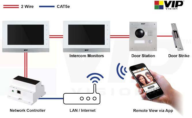
7 2. Installation If this is your first time purchasing a VIP 2-Wire Residential Intercom, we recommend setting it up on the bench first, before installation. If you are setting up more than one Door Station, or wish to connect to the Door Stations web interface, a Windows computer is required to login to the Door Station. The 2-Wire intercom requires a 2-wire cable to be run between the Indoor Monitor, Network Controller and Door Station. If you wish to connect to the system remotely, a Cat5e cable will need to be connected from the Network Controller to your existing computer network. 24V DC power must be provided for the intercom to function, it can be provided at the Indoor Monitor, Network Controller, Door Station, or mid-way through the 2-wire cable connected between the devices. The intercom components have no polarity, so it does not make a difference which wire you connect to positive or which you connect to negative. When connecting to the Door Stations web interface, the default IP address is We recommend using Internet Explorer to connect to the Door Station. Please note that the Indoor Monitor does not have a web interface. The VIP Vision 2-Wire Residential IP Intercom can be wired in either a parallel or series configuration. Parallel Configuration 24VDC Power Modem Series Configuration 24VDC Power Modem 7


8 a) 1 Indoor Monitor to 1 Door Station (No Network Functionality) This configuration requires a length of 2-wire cable running between the Indoor Monitor, and Door Station. 24V DC power must be provided to power the intercom system. Power can be provided to the Door Station, Indoor Monitor, or mid-way through the 2-wire cable. 24VDC Power 1. Install each unit at their respective location and connect the devices together with a figure 8 cable. 2. Connect the 24V DC power supply to the figure 8 cable. 3. You have now successfully connected your 2-Wire Residential IP Intercom 8
9 b) 1 Indoor Monitor to 1 Door Station via a Network Controller This configuration allows you to connect your Indoor Monitor and Door Station together, and also provide them with network access. 2-wire cables will need to be run between the Indoor Monitor, Door Station, and Network Controller. 24V DC power must be provided to power the intercom system. Power can be provided to the Door Station, Indoor Monitor, Network Controller, or mid-way through the 2-wire cable. A Cat5e network cable will need to be connected from the Network Controller to your existing computer network. 24VDC Power Modem In this example, we are going to connect the intercom Door Station and Indoor Monitor to a Network Controller, and change the IP address of the Door Station and Indoor Monitor. Device IP Addresses (example) Room Number Door Station Master Indoor Monitor Install each unit at their respective location and connect the devices together with a 2-wire cable. 2. Connect a Cat5e cable from the Network Controller, to your existing computer network. 3. Connect the 24V DC power supply to the 2-wire cable or the Network Controller. 4. Once the Indoor Monitor has powered on, go to Settings > Project Settings > then enter password Choose Net Set and change the IP address, subnet mask, and default gateway to match your local computer network. Press OK to save. In this example we are going to change the IP address of the Indoor Monitor from to
10 6. On the Indoor Monitor go to Settings > Project Settings > then enter the password Select Search Device. You will see the Door Station s IP address listed. 8. Select the Door Station, then select Modify IP and change the IP address, subnet mask and default gateway of this Door Station from to the new IP address Press OK to save. 9. Once you have set the Door Stations IP address, select the Door Station, then the Add button. 10. Enter a name for the Door Station for example Front Gate. Press the OK button. 10
11 11. A green icon will now appear next to the IP address indicating the Door Station is connected. 12. Reset the power of both the Door Station and Indoor Monitor. 13. You have now successfully connected your 2-Wire Residential IP Intercom 11
12 c) 2 Indoor Monitors to 1 Door Station via a Network Controller This configuration allows you to connect your Indoor Monitors and Door Station together, and also provide them with network access. 2-wire cables will need to be run between the Indoor Monitors, Door Station, and Network Controller. 24V DC power must be provided to power the intercom system. Power can be provided to the Door Station, Indoor Monitor, Network Controller, or mid-way through the 2-wire cable. A Cat5e network cable will need to be connected from the Network Controller to your existing computer network. 24VDC Power Modem In this example, we will be changing each devices IP address. Device IP Addresses (example) Room Number Door Station Master Indoor Monitor Extension Indoor Monitor Install each unit at their respective location and connect the devices together with a 2-wire cable. 2. Connect a Cat5e cable from the Network Controller, to your existing computer network. 3. Connect the 24V DC power supply to the 2-wire cable or the Network Controller. 4. Once the Master Indoor Monitor has powered on go to Settings > Project Settings > then enter password
13 5. Select Product Info and set the Room No. (it must be at least 3 digits, such as 102, in our example we will be using 9901) and press OK to save. 6. Select Net Set and change the local IP address of this Indoor Monitor from to and press OK to save. 7. The other Indoor Monitor we will setup as an Extension Indoor Monitor. On the Extension Indoor Monitor go to Settings > Project Settings > then enter the password Select Product Info and set the mode to Extension. You can now set the Room Number to the same as the Master Indoor Monitor but add -1 to show that it is the first extension (such as ). Enter the IP address of the Master Indoor Monitor and press OK to save. 13
14 9. Select Net Set and change the local IP address of this Indoor Monitor from to and press OK to save. 10. On the Master Indoor Monitor, go to Settings > Project Settings > then enter the password Select Search Device. You will see the Door Station s IP address listed. 12. Select the Door Station, then select Modify IP and change the IP address, subnet mask and default gateway of this Door Station from to the new IP address Press OK to save. 14
15 13. Once you have set the Door Stations IP address, select the Door Station, then the Add button. 14. Enter a name for the Door Station for example Front Gate. Press the OK button. 15. A green icon will now appear next to the IP address indicating the Door Station is connected. 16. Reset the power of both the Door Station and Indoor Monitor. 17. You have now successfully connected your 2-Wire Residential IP Intercom. 15

16 d) 2 Indoor Monitors to 2 Door Stations via a Network Controller This configuration allows you to connect your Indoor Monitors and Door Stations together, and also provide them with network access. 2-wire cables will need to be run between the Indoor Monitors, Door Stations, and Network Controller. 24V DC power must be provided to power the intercom system. Power can be provided to the Door Station, Indoor Monitor, Network Controller, or mid-way through the 2-wire cable. A Cat5e network cable will need to be connected from the Network Controller to your existing computer network. A Windows computer is required to setup this configuration. 24VDC Power Modem In this is example, we will be changing each devices IP address. Device IP Addresses (example) Room Number Door Station Door Station Master Indoor Monitor Extension Indoor Monitor Install each unit at their respective location and connect the devices together with a 2-wire cable. 2. Connect a Cat5e cable from the Network Controller, to your existing computer network. 3. Connect the 24V DC Power supply to the 2-wire cable or the Network Controller. 4. Once the Master Indoor Monitor has powered on go to Settings > Project Settings > then enter password

17 5. Select Product Info and set the Room No. (it must be at least 3 digits, such as 102, in our example we will be using 9901). Press OK to save. 6. Select Net Set and change the local IP address of this Indoor Monitor from to Press OK to save. 7. The other Indoor Monitor we will setup as an Extension Indoor Monitor. On the Extension Indoor Monitor go to Settings > Project Settings > then enter the password Select Product Info and set the mode to Extension. You can now set the room number to the same as the Master Indoor Monitor but add -1 to show that it is the first extension (such as ). Enter the IP address of the Master Indoor Monitor Press OK to save. 17

18 9. Select Net Set and change the local IP address of this Indoor Monitor from to Press OK to save. 10. Open Internet Explorer and enter in the address bar. 11. Log in with the Default username admin, password also admin. Once logged in, go to System Config > Local Config. Change the VTO number. Each Door Station must have a different VTO number, otherwise they will not function correctly. For example, 6901 for the first Door Station and 6902 for the second Door Station. Press OK. Repeat this set for each Door Station. 18
19 12. On the Master Indoor Monitor, go to Settings > Project Settings > then enter the password Select Search Device. You will see the Door Station s IP address listed. 14. Select the Door Station, then select Modify IP and change the IP address, subnet mask and default gateway of this Door Station from to the new IP address Press OK to save. 15. Once you have set the Door Station s IP address, select the Door Station, then the Add button. 16. Enter a name for the Door Station, for example Front Gate. Channel must be Vto0. Press the OK button. 19

20 17. A green icon will now appear next to the IP address Indicating the Door Station is connected. 18. Connect your additional Door Station. 19. Select the Door Station, then select Modify IP and change the IP address, subnet mask and default gateway of this Door Station from to the new IP address Press OK to save. 20. Once you have set the Door Stations IP address, select the Door Station, then the Add button. 21. Press the right arrow, enter a name for the Door Station. Channel must be Vto Select State and turn it to On. Press the OK button. 20

21 23. On the Master Indoor Monitor go to Settings > Project Settings > then enter the password Select Network. 25. You will see the IP address of the first Door Station that is added. Ensure Enable Status is set to ON. 26. Press the right arrow to view the second Door Station. Ensure Enable Status is set to ON. 27. On the Extension Indoor Monitor go to Settings > Project Settings > then enter the password Select Network. 29. You will see the IP Address of the first Door Station that is added. Ensure Enable Status is set to ON. 30. Press the right arrow to view the second Door Station. Ensure Enable Status is set to ON. 31. Reset the power of both the Door Station and Indoor Monitor. 32. You have now successfully connected your 2-Wire Residential IP Intercom. 21

22 3. Additional Configuration a) How to change the Indoor Monitor s IP Address 1. Power on the Indoor Monitor 2. On the Indoor Monitor go to Settings > Project Settings > then enter the password Select Net Set and change the IP address of the Indoor Monitor from to the new IP Address (e.g ). Press OK to save. b) How to set up an Indoor Monitor as an Extension Monitor When you have more than one Indoor Monitor, you must setup one Indoor Monitor as the Master and all the additional monitors as Extension monitors. All the Door Station details will be entered into the Master monitor and the Extension monitors will retrieve the settings from the Master monitor. You must enter in each Extension monitor, the Master IP which is the address of the Master monitor. 1. Change the Indoor Monitors IP Address as above. 2. On the Indoor Monitor go to Settings > Project Settings > then enter the password Choose Product Info and change the Mode from Master to Extension. 4. Input the room number you wish to use. This should be the same number as your Master monitor with a - to indicate it is an extension. e.g for your first Extension monitor, and for the second. 5. Enter the IP Address of your Master monitor e.g Press OK to save. 22


23 c) How to change the Door Station s IP Address Method 1 - Using Internet Explorer (Recommended) If you have multiple Door Stations, connect and configure one Door Station at a time, otherwise you may have IP address conflicts. The default address for a Door Station will be , and your PC will need to be set to an IP address that is in the same network range as the Door Station. We suggest To be able to log in to the Door Station web interface you must be using Internet Explorer. Enabling ActiveX Controls: If this is your first time logging in, you may get a system popup asking you to install ActiveX control. Click the OK button, and the system will automatically install the ActiveX control. When finished you may need to close and re-open Internet Explorer. If you are unable to download the ActiveX file, please check whether you have ActiveX allowed under your Security Settings. Go to: Tools > Internet Options > Security > Custom Level > Then once in the Security Settings, enable all Active X related options. 2. Open Internet Explorer and enter in the address bar. 3. Log in with the default username admin, and password also admin. 4 You will then be able to go to System Config > Network Config. In this menu you can change the IP address to one that is compatible with your network, as well the corresponding gateway and subnet mask. For example Press OK to save. 5. You have now successfully set the Door Station to a new IP address and can now set up additional Door Stations if necessary. 23


24 Method 2 Setup from the Indoor Monitor If you have multiple Door Stations, connect and configure one Door Station at a time, otherwise you may have IP address conflicts. 1. Power on the Indoor Monitor. 2. On the Indoor Monitor go to Settings > Project Settings then enter the password Select Search Device. You will see the Door Station s IP address on the list. 4. Select the Door Station, then select Modify IP and change the IP address, subnet mask and default gateway of this Door Station from to the new IP address Press OK to save. 24
25 5. Once you have set the Door Stations IP address, select the Door Station, then the Add button. 6. Enter a name for the Door Station for example Front Gate. Press the OK button. 7. A green icon will now appear next to the IP address, indicating the Door Station has been added to the Indoor Monitor. 8. You have now successfully set the Door Station to a new IP Address and can now set up additional Door Stations if required. 25
26 Method 3 - Using the Config Tool PC Software If you have multiple Door Stations, connect and configure one Door Station at a time, otherwise you may have IP address conflicts. Before starting you must first have a copy of the Config Tool which can be downloaded from here: 1. Double click the ConfigTool.exe icon to open the tool. This tool will automatically scan your network to find the Door Station, and then in the device list you will see IP address, port number, subnet mask, gateway, and the unique MAC address information. 2. Select the Door Station from the list, it will have the default address of (if necessary match up the unique MAC address with the MAC Address on the devices sticker). 3. Click LOGIN, and then LOGIN again to log in to the Door Station Here you can change the IP address to one that is more compatible with your network, as well the corresponding gateway and subnet mask, for example Then click OK to save. 5. You have now successfully set the Door Station to a new IP Address and can now set up additional Door Stations if necessary.

27 d) Setting the Time and Date When using your intercom system, you will need to set the correct time and date. There are 2 different ways to set the time and date, you can setup features such as NTP and DST in the Door Stations web interface, or you can adjust the time and date from the monitor. To set the time and date from the Indoor Monitor: On the Indoor Monitor go to SETTINGS > Time. In this menu, you can adjust the date and time. To set the time and date from the Door Station: You will need to have a PC (in the same IP range) that is capable of connecting to the Web Interface of the Door Station. 1. Open Internet Explorer and input the Door Station IP Address in to the address bar. e.g. 27


28 2. Log in with the eefault username admin, password also admin. 3. You will then be able to go to System Config > Local Config > System Time. In this menu you can change the Time and Date format and Sync the Door Station to your PC time. 4. After you have made your changes, select OK. It will take a few minutes before the indoor monitor displays the new time and date. e) Indoor Monitor Volume Configuration 1. On the Indoor Monitor go to Settings > Ring. In this menu you can adjust the ring tone, and volume settings. 2. After you have made your changes, select OK. 28

29 f) Door Station Volume Configuration You will need to have a PC (in the same IP range) that is capable of connecting to the Web Interface of the Door Station. 1. Open Internet Explorer and input the Door Station IP Address in to the address bar. e.g Log in with the default username admin, password also admin. 3. Once logged in, go to System Config > Video Set > Audio Set. In this menu you can change Door Station s audio levels. VTO Mic Volume Controls the microphone volume level. VTO Beep Volume Controls the speaker sounds such as The door is unlocked. 29

30 g) Wiring an Electric Door Strike to the Door Station The Door Station has a dry contact relay. Depending on which door strike you have, will depend on how your wire the door strike, whether it be wired to the Normally Open or Normally Closed contact. When connecting the Door Station to an Electric Door Strike: - The Electric Door Strike positive (+) is connected to the 12V DC power supply positive (+). - The Electric Door Strike negative (-) is connected Door Stations COM terminal. - The 12V DC power supply negative (-) is connected to the Door Stations NO or NC terminal depending on the model of door strike. Normally Closed Door Strike Wiring Normally Open Door Strike Wiring Unlock Wiring If you wish to wire in an external button to trigger the door latch, connect the button to the terminal marked Unlock Button and GND. 30

31 h) Adjust Electric Door Strike Timing 1. You will need to have a Windows computer (in the same IP range) that is capable of connecting to the web interface of the Door Station. 2. Open Internet Explorer and input the Door Station IP Address in to the address bar. e.g Log in with the default username admin, password also admin. 4. You will then be able to go to System Config > Local Config > A&C Manager. 5. Press OK to save your changes. Unlock Responding Interval is the time (in seconds) between door strike actuations. Unlock Period is the time (in seconds) that the door stays unlocked. 31
 1.")

32 i) P2P Configuration (QR Code) The mobile application must be installed before you begin You will need to have a PC (in the same IP range) that is capable of connecting to the Web Interface of the Door Station. (If you have more than one Door Station, this procedure must be done on each Door Station.) 1. Open Internet Explorer and input the Door Station IP Address in to the IE address bar. e.g Log in with the default username of admin, password also admin. 3. You will then be able to go to System Config > Network Config > P2P. 4. Tick the Enable box and select OK. 5. After waiting 2 minutes, press the refresh button, the Status should display Online. 32


33 6. Open the mobile application. 7. On the mobile application go to MENU then Home. 8. Select Door. 9. Select Device Manager. 10. Select Add Device. 33


34 11. Select P2P 12. Give your device a name (this is for your own reference), and enter your username and password. 34


35 13. Select the picture of the QR Code on the mobile application and scan the code that you see on the Door Station s web interface. 14. Select Start Live Preview to save and connect. 15. You will be returned to the live view screen where your intercom camera will now be displayed. 16. You have now successfully connected your 2-Wire Residential IP Intercom for remote access. In the future, you can connect to your system directly from the main screen by tapping the Device Manager button, then selecting your intercom. 35
36 j) Advanced Configuration of your Intercom for Remote Access (optional) Important: Before setting up remote access for your Intercom, you will need a good understanding of computer networks. If you do not, please seek the assistance of a qualified I.T. professional. In order to connect the Intercom system for remote access, the Intercom system will need to be connected to the local computer network and use the same IP Address range. To be able to set your Intercom up for Remote Access, you will first require: An ADSL internet connection of 512/512 minimum (ADSL2 or NBN recommended). An ADSL Modem which supports Port Forwarding (such as Sapido, D-link or Netgear). An External static IP address from your Internet Service Provider. An Internal Static IP address from your Modem. A network cable between your Intercom switch and your Modem. A windows PC on your network to configure your Modem. Once you have these you can proceed to set up the Remote Access by: 1. Port forward ports 37777, 3800 in the modem, to the Internal IP address of the Intercom Door Station. 2. You should then be able to test the connection to the Intercom over the internet from a different internet connection (or from a mobile on 3G/4G). Test your Remote Access by connecting to the Intercom from the mobile app: When you are in the same building as the Intercom you will be able to connect via Wi-Fi and use the Internal IP address of the Intercom. However, when you are not where the Intercom is and wish to connect via the internet or 3G, you would use the External static IP address given to you by your Internet Service Provider. Port forwarding support: There are many different brands and models of ADSL Modems which makes them difficult to set up, this is why we must recommend an IT professional. Some manufacturers offer guides on their websites or alternatively we can recommend Third-party assistance on configuring port forwarding from sites such as: If you dont have a External Static IP address: If you do not have a external static IP address, you can setup DDNS if your modem supports it. Please refer to your modems user manual on how to setup this feature. 36
 that is capable of connecting to the Web Interface of the Door Station. 1.")
37 k) Changing Door Station Network Ports (optional) In some situations, it may be necessary to change the ports that the intercom Door Station s use. You will need to have a PC (in the same IP range) that is capable of connecting to the Web Interface of the Door Station. 1. Open Internet Explorer and input the Door Station IP Address in to the address bar. e.g Log in with the Default username admin, password also admin. 3. Once logged in, go to Network Config > Port. 4. In this menu, you can modify the ports to suit your requirements. Press OK to save the settings. 5. Select Logout > Reboot. The Door Station will now restart with the changes you have made. 37

38 l) Adding Your Door to a VIP Vision NVR (optional) If you have a VIP Vision NVR, you can add your Door Station as a camera. To do this both your NVR, and intercom Door Station must be on the same IP address range. Adding a Door Station to your NVR system will take up a single channel for each Door Station. The Door Station will be recording constantly, it is not able to be set for motion detection recording. 1. Select Main Menu > Camera > Remote. 2. Select Device Search. The intercom Door Station will be listed in the top row. 3. Put a tick in the box next to the IP address, then select Add. The Door Station will now be added to your VIP Vision NVR. 38

39 4. How to Use Your Intercom System How to make a call from the Door Station After installation is complete, you can simply press the call button on the Door Station to call all Indoor Monitors simultaneously. How to answer a call using the Indoor Monitor When receiving an incoming call, you can choose to answer the call or reject the call or unlock the door. You can unlock the door while taking a call. 39
. During a call you can take a snapshot from the Door Stations camera by pressing then be stored to the Indoor Monitors Micro SD Card (if fitted).")
40 How to take Videos / Snapshots from the Indoor Monitor During a call you can take a video from the Door Stations camera by pressing this will record audio and video which will then be stored in the Indoor Monitors Micro SD Card (If fitted). During a call you can take a snapshot from the Door Stations camera by pressing then be stored to the Indoor Monitors Micro SD Card (if fitted). this image will Automatically capture screenshots from the Indoor Monitor You can also auto capture snapshots to the Micro SD Card (If fitted) when someone rings the Door Station and no one answers the call. On the Indoor Monitor go to Settings and set Autocapture to On. How to view your Videos / Snapshots from the Indoor Monitor On the Indoor Monitor go to Message > Video Pictures. Select Records to view messages visitors have left, or Pictures to few snapshots. Select the file and press View 40

41 Calling Between Indoor Monitor (When you have more than one monitor) If you have more than one Indoor Monitor, you may wish to call between monitors. On the Indoor Monitor go to Video Talk > Call User. If you are calling from the Master monitor to an Extension monitor, enter -1. If you are calling from an Extension monitor to the Master monitor, enter the room number, e.g Create Favorites You can create favorites to call between room, instead of dialing the room number each time you wish to make a call. On the Indoor Monitor go to Video Talk > Call User. 1. Select the favorite option. 2. Select the Add button. 41


42 3. Enter a name for the room, and the room number. Select the Save button to save your changes. 4. The device will now be added to the favorites list. Select the name and then press the Call button. 42
43 Troubleshooting Please refer to the FAQ table below for easy troubleshooting. The table below describes some typical problems and their solutions. Please consult these guides before contacting your place of purchase. Problem No power No live video Cannot connect to one device when it has been programmed. Door Station and monitors not connecting Touch screen not responsive Door Station makes an alarm sound when it is turned on. Unable to login to the Door s Station web interface Web interface not displaying correctly Second monitor not ringing Solution - Check power cord connection. - Confirm that there is power from the outlet. - Ensure that the 24V DC PSU is connected - Check the Door Station s cable and connections. - Check the Indoor Monitors cable and connections. - Try to ping the device IP address from a PC. - Reboot All Devices and Wait 5 minutes to ensure all devices have finished loading. - Check there are no breaks in the cable. - Press the unlock and menu button together, and re-calibrate the screen. - Check that the tamper switch is fully depressed. - Ensure your computer is in the same IP address range as the Door Station. - Ensure you are using Internet explorer to connect to the Door Station. - Ensure you are using Internet Explorer to connect to the Door Station. - Clear your Internet Explorer search history. - Connect to the Door Stations web interface, and ensure Group Call is selected. 43
44 Limited Warranty Cornick Pty Ltd (Seller) warrants its products to be in conformance with its own plans and specifications and to be free from defects in materials and workmanship under normal use and service for forty eight months from the date of original purchase. Sellers obligation shall be limited to repairing or replacing, at its option, free of charge for materials or labor, any part which is proved not in compliance with Sellers specifications or proves defective in materials or workmanship under normal use and service. Seller shall have no obligation under this Limited Warranty or otherwise if the product is altered or improperly repaired or serviced by anyone other than Seller. For Warranty Service: Return transportation prepaid with a copy of your purchase receipt and contact details to: Cornick, Unit 1/9 Hannabus Place, Mulgrave, NSW 2756 Australia. Seller has no obligation to attend the buyer s location to retrieve the goods or make repairs onsite. There are no warranties, expressed or implied, of merchant ability, or fitness for a particular purpose or otherwise, which extend beyond the description on the face hereof. In no case shall seller be liable to anyone for any consequential or incidental damages for breach of this or any other warranty, express or implied, or upon any other basis of liability whatsoever, even the loss or damage is caused by its own negligence or fault. Seller does not represent that the products it sells may not be compromised or circumvented; that the products will prevent any personal injury or property loss by burglary, robbery, fire or otherwise; or that the products will in all cases provide adequate warning or protection. Customer understands that a properly installed and maintained alarm system or video surveillance system may only reduce the risk of a burglary, robbery, or fire without warning, but it is not insurance or a guarantee that such will not occur or that there will be no personal injury or property loss as a result. Consequently, seller shall have no liability for any personal injury; property damage or other loss based on a claim the product failed to give any warning. However, if seller is held liable, whether directly or indirectly, for any loss or damage arising under this limited warranty or otherwise, regard less of cause or origin, seller's maximum liability shall not in any case exceed the purchase price of the product, which shall be the complete and exclusive remedy against seller. This warranty replaces any previous warranties and is the only warranty made by the Seller on this product. No increase or alteration, written or verbal, of the obligations of this Limited Warranty is authorized. Please refer to the website ( for a full list of trading terms. 44
Residential IP Intercom Kit
 www.rhinoco.com.au MODEL: INTIPRKITB Residential IP Intercom Kit Includes Door station and Indoor Monitor QUICK INSTALLATION GUIDE N517 Indoor Monitor Door Station - Advanced H.264 Video Compression Technology
Professional IP Surveillance Pack
 www.vip-vision.com MODEL: NVR4PROPACK Professional IP Surveillance Pack Network Video Recorder with 4 Security Cameras QUICK INSTALLATION GUIDE N517 NVR 4 x IP Day/Night Cameras - Advanced H.264 Video
Professional Surveillance Pack
 www.watchguardalarms.com.au MODEL: DVR8ENTPACK Professional Surveillance Pack Digital Video Recorder with 8 Security Cameras QUICK INSTALLATION GUIDE N517 Digital Video Recorder (DVR) 4 x 15 Infrared Day/Night
Professional Surveillance Pack
 www.watchguardalarms.com.au MODEL: DVR8E(PACK) Professional Surveillance Pack Digital Video Recorder with 8 Security Cameras QUICK INSTALLATION GUIDE N517 Digital Video Recorder 8 x 15m IR Day/Night Cameras
Professional IP Surveillance Pack
 www.vip-vision.com MODEL: NVR16PRO(PACK)3NP Professional IP Surveillance Pack Network Video Recorder with 16 Security Cameras QUICK INSTALLATION GUIDE N517 NVR 16 x IP Day/Night Cameras - Advanced H.264
zclock-200w User Manual
 zclock-200w User Manual Table of contents Product Diagram......Page 1 Alarm clock operation......page 5 Setting up Hidden Cam.....Page 7 Advanced set up......page 14 Windows......Page 15 Apple OSX...Page
Professional Surveillance Pack
 www.watchguardalarms.com.au MODEL: DVR8ENTPACK3 Professional Surveillance Pack Digital Video Recorder with 8 Security Cameras QUICK INSTALLATION GUIDE N517 Digital Video Recorder (DVR) 4 x 15 Infrared
Professional IP Surveillance Pack
 www.vip-vision.com MODEL: NVR8PRO(PACK)3 Professional IP Surveillance Pack Network Video Recorder with 8 Security Cameras QUICK INSTALLATION GUIDE N517 NVR 8 x IP Day/Night Cameras - Advanced H.264 Video
SOFTWARE VERSION 3.3. CD P/N Rev. C
 SOFTWARE VERSION 3.3 CD P/N 7301538 Rev. C 2 4 Introduction 1 4 General Specification: 1.1 4 Factory defaults parameters: 1.2 5 Basic Functionality 1.3 5 Password Protection 1.4 6 Operation 1.5 6 SMS support
 www.watchguardalarms.com.au MODEL: DVR8ENTPACK4 Professional Surveillance Pack Digital Video Recorder with 8 Security Cameras QUICK INSTALLATION GUIDE N517 Digital Video Recorder (DVR) 4 x 15m Infrared
NAPCO iseevideo Fixed IP Camera User Guide
 333 Bayview Avenue Amityville, New York 11701 For Sales and Repairs, (800) 645-9445 For Technical Service, (800) 645-9440 Publicly traded on NASDAQ NAPCO 2008 R Symbol: NSSC NAPCO iseevideo Fixed IP Camera
Wireless Doorphone Intercom
 Security Made Smarter Wireless Doorphone Intercom EN INSTRUCTION MANUAL DOORBELL OVERVIEW MICROPHONE LEDS CAMERA LENS LIGHT SENSOR Detects ambient light and turns on the LEDS to provide clear color night
2-Way Wireless I/O Expander Installation Guide
 2-Way Wireless I/O Expander Installation Guide For more detailed information please refer to the iconnect Installer Manual provided on our website: www.electronics-line.com Table of Contents 1. Introduction...
INSTALLATION INSTRUCTIONS
 General Information INSTALLATION INSTRUCTIONS K3129-2V1 7/98 FA210RF Keypad/Transceiver The FA210RF Keypad/Transceiver is a combination unit. It replaces a FA210KP Fixed Addressable Keypad, 5881/5882M
WELCOME. For customer support or any inquiries, please visit our web site at or contact us at
 WELCOME Congratulations on purchasing the GBF Smart Four Wire Intercom System. Our factory engineers were the first to enable multiple security cameras being monitored through a smart mobile device and
IOX-4. Installation Instructions. AXS-100 I/O Expander 1. INTRODUCTION 2. SPECIFICATIONS 3. MOUNTING DE6314 1
 AXS-100 I/O Expander 1. INTRODUCTION The is an input / output expander for the AXS-100 access control panel. It contains eight analog inputs and eight dry contact relays output. Up to four boards may be
Introduction. 1. RF Module
 Introduction RISCO Groupʹs 2 Way Wireless I/O & X10 Module is an extension module enabling wired devices to be connected to the Agility Wireless system. The Wireless I/O Module supports 4 hardwired zones,
ISEE-SCHGW User Guide
 333 Bayview Avenue Amityville, New York 11701 For Sales and Repairs, (800) 645-9445 For Technical Service, (800) 645-9440 Publicly traded on NASDAQ NAPCO 2008 R Symbol: NSSC NAPCO ISEE-SCHGW User Guide
F Series Indoor Fixed IP Camera. Quick Start Guide
 F Series Indoor Fixed IP Camera Quick Start Guide Welcome Thank you for purchasing our IP camera! Before install and use the IP camera, please read the following section carefully. Please keep this start
VDP RANGE. Quick Installation Guide. tel: +44 (0) fax: +44 (0) web:
 fax: +44 (0) web:") VDP RANGE Quick Installation Guide Official UK distribution partner tel: +44 (0)1457 874 999 fax: +44 (0)1457 829 201 email: sales@cop-eu.com web: www.cop-eu.com Home System Configuration When configuring
VDP RANGE Quick Installation Guide Official UK distribution partner tel: +44 (0)1457 874 999 fax: +44 (0)1457 829 201 email: sales@cop-eu.com web: www.cop-eu.com Home System Configuration When configuring
For use with QED controls panels ONLY
 Previous Menu K3129 5/98 6128RF Keypad/Transceiver INSTALLATION INSTRUCTIONS For use with QED controls panels ONLY General Information The 6128RF Keypad/Transceiver is a combination unit. It replaces a
VIDEO DOOR ENTRY FEBRUARY Quick Install Guide. tel: +44 (0) fax: +44 (0) web:
 fax: +44 (0) web:") FEBRUARY 2017 Quick Install Guide VIDEO DOOR ENTRY Official UK distribution partner tel: +44 (0)1457 874 999 fax: +44 (0)1457 829 201 email: sales@cop-eu.com web: www.cop-eu.com Home System Configuration
FEBRUARY 2017 Quick Install Guide VIDEO DOOR ENTRY Official UK distribution partner tel: +44 (0)1457 874 999 fax: +44 (0)1457 829 201 email: sales@cop-eu.com web: www.cop-eu.com Home System Configuration
SVT-WIFI Video Intercom System C
 SVT-WIFI Video Intercom System C User Manual Please read this user manual prior to installing the system, and keep it well for future use. CONTENTS 1. Parts and Functions... 1 2. Terminal Descriptions...
SD1306. Speed Dome IP Camera. Quick User Guide
 SD1306 Speed Dome IP Camera Quick User Guide Table of Contents I. Camera Introduction... 1 1. Package Contents... 1 2. Hardware Installation... 2 2.1 Factory Default... 6 3. SD card Compatibility List...
Digital Electronic Lock OWNER S MANUAL
 CAL-ROYAL CR3000 Digital Electronic Lock OWNER S MANUAL THANK YOU for purchasing CAL-ROYAL CR 3000 Digital Lock. Your new CAL-ROYAL CR3000 Digital Lock advanced features include: 1 Master Code for entry
DP-234Q (NTSC) DP-734Q (PAL) Hands-Free Video Door Phone Manual
 DP-734Q (PAL) Hands-Free Video Door Phone Manual") DP-234Q (NTSC) DP-734Q (PAL) Hands-Free Video Door Phone Manual Screen image simulated. * has four LEDs for nighttime operation Remotely and securely talk to visitors and unlock doors, gates, etc. from
DP-234Q (NTSC) DP-734Q (PAL) Hands-Free Video Door Phone Manual Screen image simulated. * has four LEDs for nighttime operation Remotely and securely talk to visitors and unlock doors, gates, etc. from
DP-222Q Color Video Door Phone Manual
 DP-222Q Color Video Door Phone Manual * has 6 LEDs for nighttime operation Remotely and securely talk to visitors and unlock doors, gates, etc. from the Easily connect a secondary * Simple 2-wire connection
FW2 MERLIN PRO Manual ==============================
 FW2 MERLIN PRO Manual ============================== PROGRAMMABLE STAND ALONE 2WAY WIRELESS TRANSCEIVER Installation and Programming Guide WWW.THECROWGROUP.COM ELECTRONIC ENGINEERING LTD. P/N 7106452 Rev.
DP-222Q Color Video Door Phone Manual
 DP-222Q Color Video Door Phone Manual * has 6 LEDs for nighttime operation Remotely and securely talk to visitors and unlock doors, gates, etc. from the Easily connect an secondary * Simple 2-wire connection
212iL Rev. 1.1
 212iL 1 International Electronics, Inc. 427 Turnpike Street Canton, Massachusetts 02021 212iL (illuminated Luxury) Keypad Single Unit Keypad- Control Installation Manual Features: 120 User Capability Illuminated
For use with QED and hardwired control panels ONLY!
 K3129V2 7/98 6128RF Keypad/Transceiver INSTALLATION INSTRUCTIONS For use with QED and hardwired control panels ONLY! General Information The 6128RF Keypad/Transceiver is a combination unit. It replaces
Unit Door Station User's Manual ----VTO12XX Series
 Unit Door Station User's Manual ----VTO12XX Series V1.2.0 Welcome Thank you for purchasing our product! This quick start guide is designed to be a reference tool for your system. Please keep it well for
Agility 2-Way Wireless Slim Keypad
 Agility 2-Way Wireless Slim Keypad Models: : RW132KL1, RW132KL1P Instruction Manual Agility 2-Way Wireless Slim Outdoor Keypad Table of Contents INTRODUCTION 3 MAIN FEATURES 3 COMMUNICATION SETUP 3 MOUNTING
NAPCO NetLink NET-COMM
 333 Bayview Avenue Amityville, New York 11701 For Sales and Repairs, (800) 45-9445 For Technical Service, (800) 45-9440 Publicly traded on NASDAQ Symbol: NSSC R NAPCO NetLink NET-COMM Internet Communication
NAPCO NetLink. Getting Started Guide INTRODUCTION. Napco 2004 WI1298A 7/04
 333 Bayview Avenue Amityville, New York 11701 For Sales and Repairs, (800) 645-9445 For Technical Service, (800) 645-9440 R NAPCO NetLink Getting Started Guide Napco 2004 WI1298A 7/04 INTRODUCTION Thank
IP Apartment System Quick Start Guide
 IP Apartment System Quick Start Guide Version 1.0.0 Welcome Thank you for purchasing our device! This quick start guide will help you become familiar with our device in a very short time. Before installation
300 Series Cube Wireless HD Surveillance Camera with Microphone. Installation Manual. Important! Ensure your NVR has the latest firmware!
 300 Series Cube Wireless HD Surveillance Camera with Microphone Installation Manual Important! Ensure your NVR has the latest firmware! Read this page before you go to the job site! 2 For maximum control
V-9908 MESSAGE/PAGE PANEL
 Issue 4 V-9908 MESSAGE/PAGE PANEL Introduction These instructions contain the specifications and guidelines necessary to install, operate, and maintain the V-9908, /Page Panel. The V-9908 /Page Panel provides
8 WiFi Digital Photo Frame with Touchscreen LCD Display Instructional Manual
 8 WiFi Digital Photo Frame with Touchscreen LCD Display Instructional Manual aluratek.com mnl M10438 model AWDMPF8BB Copyright 2017 Aluratek, Inc. All Rights Reserved. Table of Contents Frame Features...
QUICK GUIDE. Camera Installation for iphone, ipad, Android smart phone and tablet
 QUICK GUIDE Camera Installation for iphone, ipad, Android smart phone and tablet For Technical questions, please email: info@trivisiontech.com 1 Contents 1.0 Introduction ----------------------------------------------------------------------3
2-Wire ECL-VIP200 User s Manual
 2-Wire ECL-VIP200 User s Manual V1.0.0 i Table of Contents Table of Contents...i 1 Product Overview... 1 1.1 List of Models... 1 1.2 Structure... 1 1.2.1 Dimension... 1 1.2.2 Front Panel... 2 1.2.3 Rear
power port make sure the ac adapter is plugged into the correct port Make sure to include at the beginning.
 Quickstart Guide If you have a blank SD card, you may insert it into the camera. To set up your camera for use on the network, connect the camera's wired network port to a router. Connect the AC adapter
2N Telecommunications H.I.M. USER GUIDE Helios Interface Module
 2N Telecommunications H.I.M. USER GUIDE Helios Interface Module PRODUCT DESCRIPTION The Helios Interface Module (HIM) is designed to connect the Helios Door Phone device to all telephones connected to
8 WiFi Digital Photo Frame with Touchscreen LCD Display Instructional Manual
 8 WiFi Digital Photo Frame with Touchscreen LCD Display Instructional Manual aluratek.com mnl M10424 model AWDMPF208F Copyright 2016 Aluratek, Inc. All Rights Reserved. Table of Contents Frame Features...
Trilogy DL5200 Programming Instructions OI345 10/08
 345 Bayview Avenue Amityville, New York 11701 For Sales and Repairs 1-800-ALA-LOCK For Technical Service 1-800-645-9440 ALARM LOCK 2008 CONGRATULATIONS! Trilogy DL5200 Programming Instructions OI345 10/08
iminicam 1080p Wireless Spy Camera User Manual
 iminicam 1080p Wireless Spy Camera User Manual imini Spy Camera User Manual Introduction Thank you for choosing the imini Spy Camera. Experience cutting edge technology and enjoy the security that the
8 WiFi Digital Photo Frame with Touchscreen LCD Display Instructional Manual
 8 WiFi Digital Photo Frame with Touchscreen LCD Display Instructional Manual aluratek.com mnl M10424 model AWDMPF208F Copyright 2017 Aluratek, Inc. All Rights Reserved. Table of Contents Frame Features...
Professional IP Intercoms Product Reference Guide
 Professional IP Intercoms Product Reference Guide Stay connected with all that you love. Stay connected with all that you love. It is our mission to keep you in touch with the important things in life,
Falcon SM200 Series Camera
 Falcon Series Camera Quick Start Guide Package Contents Camera with Mount Base 1 Flexible Clamp with Fixing Screws 1 Power Adapter 1 Wall Mounting Screws 1 Terminal Block for Alarm I/O 1 Quick Start Guide
All the registered trademarks referred to this manual are belonging to their respective companies.
 MiniDE User Manual COPYRIGHT and TRADEMARK All rights reserved by APANTA LCC, Porland, Oregon, USA. No part of this document may be reproduced in any form or by any means without written permission from
H.264 HD HDMI Encoder for IP TV. Operation Instructions
 H.264 HD HDMI Encoder for IP TV Operation Instructions Table of Contents 1. Features...3 2. Package Contents... 3 3. Hardware Description... 4 4. Typical Application... 4 5. Environment Configuration...
ASCL1 / ASCL2 CarLink Guide for Android Users
 ASCL1 / ASCL2 CarLink Guide for Android Users 2012 Audiovox Electronics Corporation. All rights reserved. CarLink Guide for Android Users New Account Creation After having CarLink installed, follow the
Welcome Contents Diagram
 Welcome Congratulations on your purchase of our GBF PL960 Series of IP Doorbells. Our factory engineers were the first to enable viewing of multiple security cameras through your handheld smart device,
WiFi Video Doorbell. User Manual
 WiFi Video Doorbell User Manual Introduction Content With Hisilicon Hi3518E processor and H.264 compression technology, this Wifi video intercom provides smooth realtime video transmission while keeps
cb 1500 quick start guide & user manual Time and Attendance Made Simple...
 cb 1500 quick start guide & user manual Time and Attendance Made Simple... and Smart! ABC Office 1142 West Flint Meadow Drive, Kaysville, UT 84037 (800) 658-8788 www.abcoffice.com Sign-up Thank you for
FREUND SIP IPDS-20A INTERCOM USER MANUAL. FREUND ELEKTRONIK A/S Fuglebakken Odense NV Denmark Tlf.
 FREUND SIP IPDS-20A INTERCOM USER MANUAL Contents 1. Product Overview... 4 1.1 Instruction... 4 1.2 At a Glance... 5 1.3 Daily Use... 6 1.3.1 Making a Call... 7 1.3.2 Receiving a Call... 7 1.3.3 Unlock
A-100 INDOOR STAINLESS STEEL KEYPAD WIRING & PROGRAMMING INSTRUCTIONS
 345 Bayview Avenue Amityville, New York 11701 For Sales and Repairs 1-800-ALA-LOCK For Technical Service 1-800-645-9440 Publicly traded on NASDAQ Symbol: NSSC ALAR LOCK 2006 INDOOR STAINLESS STEEL KEYPAD
Hik-Connect Mobile Client Software (ios)
") User Manual V1.1.0 UD01586B 1 COPYRIGHT 2015 Hangzhou Hikvision Digital Technology Co., Ltd. ALL RIGHTS RESERVED. Any and all information, including, among others, wordings, pictures, graphs are the properties
User Manual V1.1.0 UD01586B 1 COPYRIGHT 2015 Hangzhou Hikvision Digital Technology Co., Ltd. ALL RIGHTS RESERVED. Any and all information, including, among others, wordings, pictures, graphs are the properties
INSTALLATION MANUAL. SIM/SIK/SI-8000 IP Intercom System ELITE
 INSTALLATION MANUAL SIM/SIK/SI-8000 IP Intercom System ELITE SIM/SIK/SI- 8000Series IP Intercom System QUICK START GUIDE CONTENTS Introduction Specifications and Package Contents 1 Dimensions 2 Installation
Optus Blitz ZTE BLADE V7 LITE Quick Start Guide
 Optus Blitz ZTE BLADE V7 LITE Quick Start Guide Search ZTE Australia on Facebook, Google+ and Twitter to keep in touch. ZTE 2016 Ver 1.0 May 2016 Copyright 2016 by ZTE Corporation All rights reserved.
Digital Villa VTO (VTO2 series) User s Manual
 User s Manual") Digital Villa VTO (VTO2 series) User s Manual V1.0.0 Table of Contents 1 Product Overview... 1 1.1 Intro to Product... 1 1.2 Applicable Models... 1 2 Structure... 2 2.1 Front Panel... 2 2.2 Rear Panel...
Digital Villa VTO (VTO2 series) User s Manual V1.0.0 Table of Contents 1 Product Overview... 1 1.1 Intro to Product... 1 1.2 Applicable Models... 1 2 Structure... 2 2.1 Front Panel... 2 2.2 Rear Panel...
Installation Manual & User Instructions. MultiCom 500
 Installation Manual & User Instructions For MultiCom 500 Multi resident GSM Intercom System Contents Section Description Page 1 Introduction 3 2 Getting started 3 3 SIM card 3 4 Wiring 4 5 Keypad / onscreen
7-inch Digital Intercom Monitor User s Manual
 7-inch Digital Intercom Monitor User s Manual V1.0.1 Table of Contents 1 General Introduction... 5 1.1 Product Intro... 5 1.2 Applicable Model... 5 2 Structure and Appearance... 6 2.1 Front Panel... 6
Network Video Recorder Quick Start Guide
 Network Video Recorder Quick Start Guide Contents Important Safeguards and Warnings... 2 1. Hardware Installation and Connection...2 1.1. Before You Start... 3 1.2. HDD Installation... 3 2. Interface Instruction...4
GSM Door / Gate Intercom Entry System For 123 Units max.
 USER MANUAL USA VERSION GSM Door / Gate Intercom Entry System For 123 Units max. GSM-DE2123 Speaker LCD Display Microphone Please read this user manual and the quick setup guide completely and keep it
Algo 8028 SIP Doorphone Manual. Empowered by Innovation P/N ALGO
 Empowered by Innovation Algo 8028 SIP Doorphone Manual P/N 1093100ALGO August 19, 2015 Printed in U.S.A. For additional resources, visit our Technical Support site on the web at http://www.necdsx.com.
HOME SECURITY KIT. USER MANUAL SMART PROTECTION WITH THE ALL-IN-ONE SOLUTION. SMART WINDOW SENSOR SMART POWER SOCKET SMART MOTION SENSOR SMART IP CAM
 HOME SECURITY KIT. SMART PROTECTION WITH THE ALL-IN-ONE SOLUTION. SMART WINDOW SENSOR SMART POWER SOCKET SMART IP CAM SMART MOTION SENSOR USER MANUAL SL-900100/900111 HOME SECURITY KIT A/B SHORT INSTRUCTION
300 Series Mini Dome IP-Enabled HD Surveillance Camera with Microphone. Installation Manual. Important! Ensure your NVR has the latest firmware!
 300 Series Mini Dome IP-Enabled HD Surveillance Camera with Microphone Installation Manual Important! Ensure your NVR has the latest firmware! Read this page before you go to the job site! 2 For maximum
Digital VTH (Version 4.0)
") Digital VTH (Version 4.0) Quick Start Guide V1.0.2 Cybersecurity Recommendations Mandatory actions to be taken towards cybersecurity 1. Change Passwords and Use Strong Passwords: The number one reason
Digital VTH (Version 4.0) Quick Start Guide V1.0.2 Cybersecurity Recommendations Mandatory actions to be taken towards cybersecurity 1. Change Passwords and Use Strong Passwords: The number one reason
VTO2000A Series User s Manual
 VTO2000A Series User s Manual V1.1.0 1 Table of Contents Table of Contents... 2 1 Product Overview... 1 1.1 List of Models... 1 1.2 Structure... 1 1.2.1 Structure... 1 1.2.2 Front Panel... 2 1.2.3 Rear
LITE TUNES #V
 LITE TUNES #V45000-71 Thank you for purchasing this new Sylvania LITE TUNES. This LITE TUNES assembles in minutes. The LITE TUNES: CARTON INCLUDES: 1 Litetunes 2 Remote controls 1 Set ground stake 1 Audio
Telephone Line Monitor USER GUIDE
 Telephone Line Monitor USER GUIDE For Technical Assistance call the Manufacturers direct Ph 800 530 8645 8AM - 5PM West Coast Pacific Time NATCOMM USA LLC Responsible Supplier Code NC OPERATION Our Telephone
Bluetooth Stereo Headset
 Bluetooth Stereo Headset RF-BTHP01 User Guide Bluetooth Stereo Headset Contents Features... 3 Package contents... 3 Components... 4 Using your headset... 5 Charging the battery... 5 Turning your headset
3MP WI-FI SECURITY CAMERA QUICK START GUIDE ENGLISH
 3MP WI-FI SECURITY CAMERA QUICK START GUIDE ENGLISH WELCOME! Congratulations on your latest purchase and welcome to the Q-See family. This guide will help get your camera up and running. WHAT S INCLUDED
PA-SIP PAGING SWITCH. For Technical Assistance call the Manufacturers direct ph AM - 5PM West Coast Pacific Time
 PA-SIP PAGING SWITCH For Technical Assistance call the Manufacturers direct ph 800 530 8645 8AM - 5PM West Coast Pacific Time NATCOMM USA LLC Responsible Supplier Code :NC PACKING LIST PA-SIP Paging Switch
ASCL1 / ASCL2. CarLink Guide for BlackBerry Users Audiovox Electronics Corporation. All rights reserved.
 ASCL1 / ASCL2 CarLink Guide for BlackBerry Users 2012 Audiovox Electronics Corporation. All rights reserved. CarLink Guide for BlackBerry Users New Account Creation After having CarLink installed, follow
Installation Manual & User Instructions. MultiCom 100 / 500
 Installation Manual & User Instructions For MultiCom 100 / 500 Multi apartment GSM Intercom System 1 P a g e M u l t i c o m 1 0 0 i n s t a l l i n s t r u c t i o n s v 1 Contents Section Description
TENVIS Technology Co., Ltd. User Manual. For H.264 Cameras. Version 1.0.0
 TENVIS Technology Co., Ltd User Manual For H.264 Cameras Version 1.0.0 Catalogue Basic Operation... 3 Hardware Installation... 3 Search Camera... 3 For Internet Explorer... 6 Playback Record Files... 9
Remote Refrigeration Control
 Remote Refrigeration Control Installation & Operation Bulletin No. H-IM-RRC June 2018 Part Number 25092901 Replaces H-IM-RRC (01/17) Remote Refrigeration Control Installation Start Up Troubleshooting Operation
QUICK USER MANUAL WINDOWS TABLET 8 & 10
 1 Index Getting to know your Tablet 3 Windows Keyboard (Optional accessory) 4 Desktop Introduction 5 Swipe Functions 5 Introduction to app Interface 7 Charm Bar menu 8 Dual-Screen Mode 9 Basic Operations
3M Sorter System FX. Administrator s Guide
 3M Sorter System FX Administrator s Guide 3M 2010. All rights reserved. 3M Sorter System FX Administrator s Guide, 78-8129-3969-8, Rev A 3M is a trademark of 3M. Microsoft and Windows are either trademarks
IP Camera User Manual
 Statement IP Camera User Manual If the user manual cannot help you to solve the problem, please call our technology center about the solutions. We will update the content for the new functions without
ST-HD-CVR4CH ST-HD-CVR8CH ST-HD-CVR16CH. Professional Digital Video Recorders QUICK START GUIDE
 ST-HD-CVR4CH ST-HD-CVR8CH ST-HD-CVR16CH Professional Digital Video Recorders QUICK START GUIDE 1 Thank you for your purchase of this SecurityTronix HD-COAXINATOR Video Recorder (CVR). Documentation for
Unit Door Station User's Manual ----VTO12XX Series
 Unit Door Station User's Manual ----VTO12XX Series V1.1.0 Welcome Thank you for purchasing our product! This quick start guide is designed to be a reference tool for your system. Please keep it well for
User Instructions. For WiFi (PRO 2) Manual Version 1. For warranty, service and support, contact:
 Manual Version 1. For warranty, service and support, contact:") User Instructions For WiFi (PRO 2) Manual Version 1 For warranty, service and support, contact: Installed By: Install Company Name: Installer Phone Number: Installer Email Address: Date of Install: Note:
User Instructions For WiFi (PRO 2) Manual Version 1 For warranty, service and support, contact: Installed By: Install Company Name: Installer Phone Number: Installer Email Address: Date of Install: Note:
D3D Security Pvt ltd
 D3D Security Pvt ltd Copyright Notice @ 2017 D3D. All right reserved. All text instructions on product information and services are protected by copyright or other intellectual property, any use of the
TALKBACK INTERCOM SYSTEM V-2926 OPTION BOARD
 Issue 8 TALKBACK INTERCOM SYSTEM V-2926 OPTION BOARD The V-2926 Option Board is an add-on feature for the V-2924A Expandable Zone Talkback Intercom System. The addition of this board provides the following
Trilogy DL1200ET Programming Instructions WI1686 7/08
 345 Bayview Avenue Amityville, New York 11701 For Sales and Repairs 1-800-ALA-LOCK For Technical Service 1-800-645-9440 Publicly traded on NASDAQ Symbol: NSSC ALARM LOCK 2008 Trilogy DL1200ET Programming
Sotion Wireless Camera. User Manual.
 Sotion Wireless Camera User Manual Email: Help@sotiongroup.com App Download & Installation The camera is compatible with Wi-Fi 2.4 GHz only, please connect camera to 2.4 GHz Wi-Fi. Make sure your network
EAS DIGITAL/ANALOG OVERRIDE INTERFACE Model 988 PC Software version 1.06
 Instruction Manual EAS DIGITAL/ANALOG OVERRIDE INTERFACE Model 988 PC Software version 1.06 Emergency Alert Systems CATV Switching and Control 585-765-2254 fax 585-765-9330 100 Housel Ave. Lyndonville
User Manual. Wireless IP Camera
 User Manual Wireless IP Camera Introduction Hi. Thank you for purchasing the AUKEY VT-CM1 Wireless Security IP Camera. Please read this user manual carefully and keep it in a safe place for future reference.
Website: Toll Free: [US] USER MANUAL. J-Tech Digital IPTV H264 Encoder.
![Website: Toll Free: [US] USER MANUAL. J-Tech Digital IPTV H264 Encoder.](/thumbs/79/79503151.jpg "Website: Toll Free: [US] USER MANUAL. J-Tech Digital IPTV H264 Encoder.") Website: www.jtechdigital.com Toll Free: 1-888-610-2818[US] Email: Support@jtechdigital.com USER MANUAL J-Tech Digital IPTV H264 Encoder RoHS JTD-ID:220 Table of Contents 1. Features... 3 2. Package Contents...
Website: www.jtechdigital.com Toll Free: 1-888-610-2818[US] Email: Support@jtechdigital.com USER MANUAL J-Tech Digital IPTV H264 Encoder RoHS JTD-ID:220 Table of Contents 1. Features... 3 2. Package Contents...
Plus-X 600. Installation and Operation Manual
 Plus-X 600 Installation and Operation Manual Table of Contents Introduction... 1 Compatibility... 1 Unpacking... 1 Front Panel Indicators... 2 Hardware Configuration... 2 Installation... 4 Software Configuration...
Digital VTO (VTO15 Series) User s Manual
 User s Manual") Digital VTO (VTO15 Series) User s Manual V1.1.0 1 1 Table of Contents 1 Table of Contents... 2 1 Product Overview... 1 1.1 VTO1520C... 1 2 Function... 3 2.1 Basic Function... 3 2.2 Call... 4 2.2.1 Call
Digital VTO (VTO15 Series) User s Manual V1.1.0 1 1 Table of Contents 1 Table of Contents... 2 1 Product Overview... 1 1.1 VTO1520C... 1 2 Function... 3 2.1 Basic Function... 3 2.2 Call... 4 2.2.1 Call
Wireless Video/Audio Intercoms
 Wireless Video/Audio Intercoms User Set-Up Guide and Instructions BEC Integrated Solutions Williamsville, New York 716-689-0871 1 Table of Contents: B-WSP1.Page 3 B-WSP2 Page 8 B-WC2..Page 13 B-WI2 Page
Let s get started. Need more help getting started?
 Need more help getting started? www.zencam.com/support Let s get started. We hope you love your new Zencam Camera. If you have any questions, we're here for you. M1. M2. E1. E2 Series support@zencam.com
Quick-Start Guide. App Cam XLight/X55/X56. Wireless IP Camera
 Quick-Start Guide App Cam XLight/X55/X56 Wireless IP Camera Use this Quick-Start Guide to connect the camera to the network and for basic installation and setup procedure. For more detailed instructions
PTT-100-VZ Wireless Speaker Microphone
 Federal Communication Commission Interference Statement This equipment has been tested and found to comply with the limits for a Class B digital device, pursuant to Part 15 of the FCC Rules. These limits
zpen-1080p Features zpen-1080p Layout
 1 zpen-1080p Features CMOS image sensor with Low Light sensitivity HD 1080P up to 30fps, 720P up to 60fps H.264 compression Built-in micro SD card, supports up to 32GB One button operation Easily download
LINESTEIN DIGITAL ADAPTER
 LINESTEIN DIGITAL ADAPTER USER GUIDE IMPORTANT! FOLLOW THE SETUP PROCEDURE IN THIS USER GUIDE WHENEVER YOU MOVE LINESTEIN TO A DIFFERENT TELEPHONE. About Your New LineStein Congratulations on purchasing