AH Motion Controller - Operation Manual
|
|
|
- Betty Dennis
- 5 years ago
- Views:
Transcription
 Ltd.")
1 Industrial Automation Headquarters Delta Electronics, Inc. Taoyuan Technology Center No.18, Xinglong Rd., Taoyuan City, Taoyuan County 33068, Taiwan TEL: / FAX: Asia Delta Electronics (Jiangsu) Ltd. Wujiang Plant Jiangxing East Road, Wujiang Economic Development Zone Wujiang City, Jiang Su Province, P.R.C TEL: / FAX: Delta Greentech (China) Co., Ltd. 238 Min-Xia Road, Pudong District, ShangHai, P.R.C TEL: / FAX: Delta Electronics (Japan), Inc. Tokyo Office Minato-ku Shibadaimon, Tokyo , Japan TEL: / FAX: Delta Electronics (Korea), Inc. 1511, Byucksan Digital Valley 6-cha, Gasan-dong, Geumcheon-gu, Seoul, Korea, TEL: / FAX: Delta Electronics Int l (S) Pte Ltd. 4 Kaki Bukit Ave 1, #05-05, Singapore TEL: / FAX: Delta Electronics (India) Pvt. Ltd. Plot No 43 Sector 35, HSIIDC Gurgaon, PIN , Haryana, India TEL : / FAX : Americas Delta Products Corporation (USA) Raleigh Office P.O. Box 12173,5101 Davis Drive, Research Triangle Park, NC 27709, U.S.A. TEL: / FAX: Delta Greentech (Brasil) S.A. Sao Paulo Office Rua Itapeva, 26-3 andar Edificio Itapeva One-Bela Vista São Paulo-SP-Brazil TEL: / FAX: Europe Delta Electronics (Netherlands) B.V. Eindhoven Office De Witbogt 20, 5652 AG Eindhoven, The Netherlands TEL : +31 (0) / FAX : +31 (0) AH Motion Controller - Operation Manual AH Motion Controller - Operation Manual AH *We reserve the right to change the information in this manual without prior notice.
2 AH Motion Controller Operation Manual Revision History Version Revision Date 1 st The first version was published. 2017/09/20
3 Preface AH Motion Operation Manual Contents P.1 Introduction... II P.1.1 Applicable Products... II P.1.2 Related Manuals... II P.2 Navigation between Manuals... III Chapter 1 Introduction to Motion Control Operation 1.1 Features of AH Motion PLCopen based Motion Control Instructions Motion Network Communications AH Motion System Configurations Basic Operating Procedures for Motion Control Specifications of AH Motion CPU General Specifications Motion Control Specifications Chapter 2 Hardware Setup 2.1 Installation CPU Rack Installation in a Control Panel Mounting a Backplane Installing a CPU/Module Wiring Basic System Configurations Wiring Power Supply Modules Wiring AH Motion CPU Modules Chapter 3 Software Setup 3.1 Installing and Uninstalling ISPSoft Installing ISPSoft Uninstalling ISPSoft i
4 3.2 Installing and Uninstalling COMMGR Installing COMMGR Uninstalling COMMGR Connecting ISPSoft with AH Motion CPU Direct connection via USB Direct connection via Ethernet Chapter 4 Operating ISPSoft 4.1 Quick Start Example Hardware Program Procedures for Creating a Project in ISPSoft Creating a Project Hardware Configuration Configuring a Module Setting the Parameters in a CPU and a Module Setting Module Parameters Setting PLC Parameters Creating a Program Adding a Ladder Diagram Basic Editing Creating a Contact and a Coil Basic Editing Inserting a Network and Typing an Instruction Basic Editing - Selection of a Network and Operation Basic Editing - Connecting a Contact in Parallel Basic Editing Editing a Comment Basic Editing Inserting an Applied Instruction Basic Editing Creating a Comparison Contact and Typing a Constant Writing a Program Checking and Compiling a Program Testing and Debugging a Program Creating a Connection Downloading a Program and Parameters Connection Test ii
5 4.6.4 Setting a Real-time Clock Chapter 5 Understanding Common Devices 5.1. Introduction Common Devices Functions of Common Devices Device List Latched Devices Input Relays (X) Output Relays (Y) Auxiliary Relays (M) Special Auxiliary Relays (SM/AM) Data Registers (D) Special Data Registers (SR/AR) Link Registers (L) Stepping Relays (S) Timers (T) Counters (C) bit Counters (HC/AC) Index Registers (E) Values and Constants (K, 16#) Floating-point Numbers (F, DF) Strings ( $ ) EtherCAT Symbols Symbols Application of Symbols Classes Data Types Using Devices, Symbols and Instructions Modifying a Symbol with an Index Register User-defined Data Type (ENUM) Chapter 6 Understanding Motion Control Devices 6.1 Motion Control Devices iii
6 Structures Applicable for Motion Control Parameters for Motion Axes Chapter 7 Motion Control Programming 7.1 Introduction Program Organization Units and Tasks Motion Control Program Program Architecture and Types in ISPSoft POUs in ISPSoft Managing the Tasks in ISPSoft Motion Control Instructions Function Blocks for AH Motion Controller CPU Axis State Transitions Axis States Axis Group State Buffer Mode Execution of Function Block Instructions The Interface of a Motion Control Function Block Timing Diagram for Input/Outputs Positions Postion Types Applicable Postions for Each Axis Type Electronic Cam Introduction of Electronic Cams Operation of an Electronic Cam Initial Setting Setting a Master/Slave Axis and Operating an Electronic Cam Starting/Stopping an Electronic Cam Operating Cyclically Creating Electronic Cam Data Creating a CAM Chart in ISPSoft Application of an Electronic Cam Using a Rotary Cutter Creating Rotary Cut Data iv
7 Chapter 8 Memory Card 8.1 Overview of Memory Cards Appearances of Memory Cards Specifications for SD Cards Using a Memory Card Formatting a Memory Card Installing and Removing a Memory Card SD Slot in a CPU Installing a Memory Card Removing a Memory Card Contents of a Memory Card Initializing a Memory Card Folder Structure in a Memory Card Reading/Writing a Memory Card Backing up the System Restoring the System CARD Utility Backup Restoration Chapter 9 Troubleshooting 9.1 Inspection and Troubleshooting Basic Inspection Clearing the Error State Troubleshooting Procedure Viewing Error Logs Error Codes and Indicators AHxxEMC-5A Analog I/O Modules and Temperature Measurement Modules AH02HC-5A/AH04HC-5A AH05PM-5A/AH10PM-5A/AH15PM-5A v
8 AH20MC-5A AH10EN-5A/AH15EN-5A AH10SCM-5A/AH15SCM-5A AH10DNET-5A AH10PFBM-5A AH10PFBS-5A AH10COPM-5A Troubleshooting for CPU ERROR Indicator ON ERROR Indicator Blinking BUS FAULT Indicator ON BUS FAULT Indicator Blinking Others Troubleshooting for I/O Modules Analog I/O Modules and Temperature Measurement Modules AH02HC-5A/AH04HC-5A AH05PM-5A/AH10PM-5A/AH15PM-5A AH20MC-5A AH10EN-5A/AH15EN-5A AH10SCM-5A/AH15SCM-5A AH10DNET-5A AH10PFBM-5A AH10PFBS-5A AH10COPM-5A Troubleshooting for Limitation Errors Software limit errors Hardware limit errors Appendices A.1 Installing the USB Driver for an AH Motion CPU on Windows 7... A-2 A.2 Device Addresses... A-5 A.3 Operating Principles of the CPU Module... A-7 A.3.1 Operation of the CPU Module... A-7 A.3.2 Operating Modes of the CPU Module... A-9 vi
9 P Preface Table of Contents P.1 Introduction... II P.1.1 Applicable Products... II P.1.2 Related Manuals... II P.2 Navigation between Manuals... III I
10 AH Motion Controller Operation Manual P.1 Introduction Thank you for purchasing the AH series Motion Controller CPU with our advanced motion control system. _P This manual introduces the concept of motion control operation, overview of software operation, motion control programming procedures, and troubleshooting information of the system. Please ensure that you understand the configuration and operations of the AH series motion control system, and use the AH series motion controller CPU correctly. To obtain required information for different system configurations, you can navigate between different manuals of AH Motion Controller series manuals and other related manuals. P.1.1 Applicable Products This manual relates to the following products - AHxxEMC-5A (AH08EMC-5A/AH10EMC-5A/AH20EMC-5A) - AH500 series modules P.1.2 Related Manuals The related manuals of the AH Motion series motion controllers are composed of the following. 1. AH Motion Controller - Hardware Manual It introduces function specifications, electrical specifications, appearances, dimensions, and etc. 2. ISPSoft User Manual It introduces the use of ISPSoft, the programming languages (ladder diagrams, instruction lists, sequential function charts, function block diagrams, and structured texts), the concept of POUs, the concept of tasks, and the operation of motion control programming. 3. AH Motion Controller - Standard Instructions Manual It introduces the elements for standard programming including devices, symbols and standard instructions. 4. AH Motion Controller - Operation Manual It introduces basic knowledge of motion control structure, software/hardware setup, quick start of software operations, devices to be used, motion control operations and troubleshooting. 5. AH Motion Controller - Motion Control Instructions Manual It introduces the elements for motion control programming including axis parameters, symbols and single axis/multi-axes motion instructions. 6. AH500 Motion Control Module Manual It introduces the specifications for the AH500 series motion control modules, the wiring, the instructions, and the functions. 7. AH500 Module Manual It introduces the use of special I/O modules of AH500 series PLCs. For example, network modules, analog I/O modules, temperature measurement modules, and etc. II
11 Preface P.2 Navigation between Manuals Before using the products, there are three manuals that should be utilized as fundamental information: AH Motion Controller - Hardware Manual, ISPSoft User Manual, and AH Motion Controller - Standard Instructions Manual. With the fundamental manuals, you can understand the basic information of hardware configuration, operation procedures of the software, and the basic instructions for using the system. P_ To obtain required information for different system configurations and applications, refer to other manuals as indicated in the table below. Reading all manuals related to your system configuration helps you make the most use of the AH series motion control system. Related manuals AH Motion Controller series manuals Fundamental General operation procedures AH Motion Controller Hardware Manual ISPSoft User Manual AH Motion Controller Standard Instructions Manual AH Motion Controller Operation Manual AH Motion Controller Motion Control Instructions Manual AH500 Motion Control Module Manual AH500 Module Manual 1. Overview of AH Motion Controller series products V 2. Setting up hardware configuration for the system for motion control applications V for communication (e.g. EtherCAT) for additional motion control modules V V for I/O extension using AH500 series modules V 3. Getting started with the software for motion control applications V for communication (e.g. EtherCAT) for additional motion control modules V V for I/O extension using AH500 series modules V 4. Programming V for motion control applications V V V for communication (e.g. EtherCAT) for additional motion control modules V III
12 AH Motion Controller Operation Manual Related manuals AH Motion Controller series manuals Fundamental _P General operation procedures AH Motion Controller Hardware Manual ISPSoft User Manual AH Motion Controller Standard Instructions Manual AH Motion Controller Operation Manual AH Motion Controller Motion Control Instructions Manual AH500 Motion Control Module Manual AH500 Module Manual for I/O extension using AH500 series modules V 5. Testing and troubleshooting for motion control applications V* for communication (e.g. EtherCAT) V V for additional motion control modules V* V for I/O extension using AH500 series modules V* V 6. Maintenance and Inspection V *Note: Information regarding Error codes and Indicators and the associate troubleshooting information are attached as Appendices for a quick reference. For the complete troubleshooting of the system, refer to AH Motion Controller Operation Manual. IV
13 1 Chapter 1 Introduction to Motion Control Operation Table of Contents 1.1 Features of AH Motion PLCopen based Motion Control Instructions Motion Network Communications AH Motion System Configurations Basic Operating Procedures for Motion Control Specifications of AH Motion CPU General Specifications Motion Control Specifications
14 AH Motion Controller Operation Manual 1.1 Features of AH Motion AH Motion Controller is the advanced motion control series with dedicated motion control CPUs and shares the same modules with AH series PLC s. Through the motion control network, such as EtherCAT, AH Motion Controller CPU can perform high-speed, high-precision machine control with the connected servo drives on the motion network. _ PLCopen based Motion Control Instructions AH Motion Controller CPUs offers motion control instructions that are standardized by PLCopen*. In addition, you can also use the conve nient function block in structions developed by Delta together with the PLCopen based instructions to optimize the control flexibility. These instructions help you achieve single-axis motion, multi-axis interpolation, G-code programming, synchronized motion (e.g. electronic cam/gear), velocity control, and torque control. You can specify the motion parameters in the motion control instructions and the axis parameters according to the application. *Note: PLCopen is an organization promoting industrial control based on IEC , which is an international standard widely adopted for PLC progr amming. For more informati on regarding PLCopen, check the official website at: Motion Network Communications The AH Motion Controller CPU with built-in motion network (e.g. EtherCAT) port can be connected with Delta servo drives that supports the same motion network to perform dat a exchange of all con trol information via high-s peed communications. In comparison with the traditi onal pulse-type motion controllers, the motion contr ol instructions in network-type controllers are sent via data communications, meaning the servo motors performance is optimized and is not limited by the interface specifications, e.g. the response frequency of the feedback from encoders. The motion network communications allows users to achieve a real-time control and monitoring system. 1-2
15 Chapter 1 In troduction to Mo tion Control Operation 1.2 AH Motion System Configurations The AH Motion Contro ller series CPU basic configurations include the AH Motion Controller CPU Network Configuration, AH500 Series Module Configuration, and Supported Software. AH Motion Controller Network Configuration - AHxxEMC-5A You can use the EtherCAT master port built in on the CPU interface to connect to slave devices such as analog and digital I/O, servo drives, AC motor drives and encoder input devices. With EtherCAT network configuration, you can design a system capable of performing very accurate sequence and motion control in a fixed cycle. 1_ AH500 Series Module Configuration With the motion backpl ane, you can also ad d AH500 series I/O modules* in addition to the EtherCAT network. AH500 series modules can be installed directly to the motion backplane where the CPU module is mounted. *Note: a fe w of AH500 ser ies I/O modules are not supported by the motion bac kplane. Refer to Ch2 System Configuration for the list of supported products. Supported Software ISPSoft is the major programming software that you use for an AH Motion Controller series. You can connect the software on the computer to the USB interface o n the CPU module through a commercially available USB cable. You can also connect ISPSoft to the Ethernet port on the CPU module w ith an Ethern et cable or to the bui lt-in RS-485 port on th e Motion backplane with a RS -485 cable and a conv erting device, e.g. IF D6500 USB/RS-485 converter. In additio n to ISPSoft, you can also use other software for configuring various applications based on different networks. Support Software ISPSoft AH Motion CPU Power Supply CPU AH I/O modules AH500 Series Module Configuration USB(RS-232) CPU Rack LAN or EtherNet/IP Bullt-In EtherCAT port Bullt-In EtherNet/IP port EtherCAT AH MotionNetwork Configuration Servo drives/encoder input slaves General-purpose slaves 1-3
16 AH Motion Controller Operation Manual 1.3 Basic Operating Procedures for Motion Control _1 n 1-4
17 Chapter 1 In troduction to Mo tion Control Operation 1_ n 1-5
18 AH Motion Controller Operation Manual 1.4 Specifications of AH Motion CPU General Specifications AHxxEMC-5A _1 Operating temperature -20~60 C Environmental Specifications Storage temperature -40~70 C Operating humidity Storage humidity Vibration/Shock resistance Operating environment Installation location 5~95% No condensation 5~95% No condensation International standards IEC , IEC (TEST Fc)/ IEC & IEC (TEST Ea) No corrosive gas exists. In a control box Pollution degree 2 General Specifications AHxxEMC-5A Remark Execution Input/Output control Programming language Instruction execution speed Constant scan cycle (ms) Program capacity (step) Installation Installation of modules Number of modules Number of tasks The program is executed cyclically. Cyclically refreshed inputs/outputs Direct inputs/outputs IEC Ladder diagram (LD), continuous function chart (CFC), structured text (ST), and sequential function chart (SFC). 0.3 ms/k steps (The scan cycle can be increased by one millisecond.) 256K steps DIN rails or screws Modules are installed directly on a backplane. Five input/output modules at most can be installed on a motion backplane. 283 tasks (32 cyclic tasks, 32 I/O interrupt tasks, 212 external interrupt tasks, 1 24V LV The inputs and outputs can be controlled through the direct inputs (DX device) and direct outputs (DY device). The scan cycle time can be specified by parameters. 1-6
19 Chapter 1 In troduction to Mo tion Control Operation General Specifications AHxxEMC-5A Remark detection, 4 timed interrupt tasks, and 2 communication interrupt tasks). Number of input/output devices X/Y devices (bit): 8192 (X0.0~X511.15/Y0.0~Y511.15) X/Y devices (word): 512 (X0~X511/Y0~Y511) Number of devices which can be used in a program 1_ Number of inputs/outputs 328 inputs/ 324 outputs (AHxxEMC) Number of inputs/outputs accessible to an CPU Input relay [X] 8192 (X0.0~X511.15) Output relay [Y] 8192 (Y0.0~Y511.15) Auxiliary relay [M] 8192 (M0~M8191) Timer [T] 2048 (T0~T2047) Counter [C] 2048 (C0~C2047) 32-bit counter [HC/AC] HC: 64 (HC0~HC63) AC: 56 (AC0~ AC55) (AHxxEMC) Data register [D] D device (bit): (D0.0~D ) D device (word): (D0~D65535) Stepping relay [S] 2048 (S0~S2047) Index register [E] 32 (E0~E31) Special auxiliary relay [SM] SM: 2048 (SM0~SM2047) Special data register [SR] SR: 2048 (SR0~SR2047) Serial communication port One RS-232(USB), One RS-485 communication port Ethernet port 10/100 M USB port Mini USB Memory card slot Supports Micro SD card (SD 2.0) Real-time clock Years, months, days, hours, minutes, seconds, and weeks The function is available when the CPU is used together with the motion backplane 1-7
20 AH Motion Controller Operation Manual Motion Control Specifications AHxxEMC-5A _1 Specifications Number of substantial axes supported Storage Unit Motor control Maximum speed Operating switch AHxxEMC-5A AH08EMC: 8 axes / AH10EMC: 16 axes / AH20EMC: 32 axes (Axis 1~axis 32) The capacity of the built-in storage is 256K steps. Motor unit and mechanical unit EtherCAT high-speed motion control system The response time is 100 Mbps. EtherCAT: 100M bps Differential input: 1 MHz Open collector input: 200 KHz Open collector output: 200 KHz RUN-STOP switch Input signal Input terminal X0.0+, X0.0-, X0.1+, X0.1-, X0.8+, X0.8-, X0.9+, X0.9-, X0.10+, X0.10-, X0.11+, X0.11-; X0.2, X0.3, X0.12, X0.13, X0.14, X0.15, X1.0, X1.1, X1.2, X1.3, X1.4, X1.5 Output terminal Y0.8, Y0.9, Y0.10, and Y0.11 Output signal External communication port Mini USB port Ethernet port EtherCAT port Memory card slot M-code G-code Supports Micro SD card The maximum capacity is 32 GB. M00~M01, M03~M101, and M103~M65535: The execution of a program pauses. (WAIT) You can use them freely. G0 (rapid positioning), G1 (linear interpolation), G2 (circular interpolation, clockwise), G3 (circular interpolation, counterclockwise), G4 (dwell), G17 (XY plane selection), G18 (ZX plane selection), G19 (YZ plane selection), G90 (absolute programming), and G91 (incremental programming) Number of counters 6 Number of high-speed capture/comparison 6 Number of interrupt devices
21 2 Chapter 2 Hardware Setup Table of Contents 2.1 Installation CPU Rack Installation in a Control Panel Mounting a Backplane Installing a CPU Module Wiring Basic System Configurations Wiring Power Supply Modules Wiring AH Motion Controller CPU Modules
22 AH Motion Controller Operation Manual 2.1 Installation This section introduces the installation of the basic configuration with backplanes and CPU/modules. For detailed installation information including other components, please refer to AH Motion Controller Hardware Manual CPU Rack Installation in a Control Panel The essential steps of installing an AH Motion Controller system begin with mounting a motion backplane. The motion controller has to be installed in a closed control box. In order to ensure that the PLC dissipates heat properly, _2 the space between the motion controller and the control box has to be larger than 50 millimeters. >50mm 10EMC 06XA 10SCM 10DNET 10COPM 16AN01T >50mm >50mm >50mm Keep the motion controller away from high-voltage equipment, high-voltage wires, and high-voltage motors. In order to prevent the temperature of a motion controller from rising, do not install the motion controller vertically on the bottom/top in the control box. Install a motion controller horizontally in the control box, as shown above. If you intend to increase the number of modules, you have to leave some space for installing the modules in the control box Mounting a Backplane Fixing a backplane by screws Mount the backplane on a plane by means of M5 screws, as illustrated below. To fix the backplane, you need to evaluate the length of a screw, the size of a thread, and whether to use a nut according to the actual condition of the plane unless there are specific specifications for a screw which are indicated in the pictures below. 1. Tighten the M5 screws in the holes indicated by a. 2-2
23 Chapter 2 Hardware Setup a a 2. Tighten the two screws in the holes indicated by b. 2_ b b Installing a DIN rail 1. The installation is applicable to a 35 millimeter DIN rail. 2. Install the mounting clips on a backplane. 3. Install the backplane on a DIN rail. Step 1: Press the hook in the direction indicated by the arrow. Step 2: Mount the DIN rail clips onto a DIN rail. Step 3: Pull the hook to fix the clips and the DIN rail. 2-3
24 AH Motion Controller Operation Manual DIN rail _2 Removing a DIN rail Step 1: Press the hook in the direction indicated by the arrow. Step 2: Remove the backplane. 1 DIN rail Installing a CPU Module Insert a module into a slot, make sure that the module is installed on the backplane properly, and tighen the the screw, as illustrated below. 1. Insert the hook under the module into the hole in the backplane. 2-4
25 Chapter 2 Hardware Setup 2. Push the module in the direction indicated by the arrow until it clicks. 2_ 3. Tighten the screw on the module. 2-5

26 AH Motion Controller Operation Manual 2.2 Wiring This section introduces the connection structure and the wiring of the basic configuration with power supplies and CPUs. For detailed wiring information including other components, please refer to AH Motion Controller Hardware Manual Basic System Configurations The AH Motion Controller series CPU basic configurations include the AH Motion Controller CPU Network Configuration, AH500 Series Module Configuration, and Supported Software. Refer to the below diagram for the overview of the system connection structure. _2 Support Software ISPSoft AH Motion CPU Power Supply CPU AH I/O modules AH500 Series Module Configuration USB(RS-232) CPU Rack LAN or EtherNet/IP Bullt-In EtherCAT port Bullt-In EtherNet/IP port EtherCAT AH MotionNetwork Configuration Servo drives/encoder input slaves General-purpose slaves Wiring Power Supply Modules Precautions Connecting AC power cables 1. Please separate the power cable of AHPS05-5A from the power cables for I/O devices and other devices. If there is much noise, connect an isolating transformer. Isolating transformer AHPS05-5A AC power supply V I/O equipment Another piece of equipment 2-6
27 Chapter 2 Hardware Setup 2. The 110 VAC cable, the 220 VAC cable, and the 24 VDC cable should be twisted, and connected to a module within a short distance. 3. Do not bundle 110 VAC cable, the 220 VAC cable, the 24 VDC cable, the (high-voltage high-current) main circuit, and the I/O signal cable together. Besides, it is recommended that the distance between adjacent cables should be more than 100 millimeters. 4. To prevent the surge resulting from lightning, please install a surge absorber in the way shown below. Surge absorber AC power supply V AHPS05-5A I/O equipment 2_ Points for attention: 1. The surge absorber and the PLC system should be grounded separately. 2. Please select the surge absorber whose working voltage is not less than the maximum allowable input voltage. Connecting DC power cables 1. AHPS15-5A is independently supplied with power by a DC power supply. Please separate the power cable of the DC power supply from the power cables for I/O devices and other devices. If there is much noise, connect an isolating transformer. Isolating transformer AC power supply V DC power supply 24 V DC AHPS15-5A I/O equipment Another piece of equipment 2. The 110 VAC cable, the 220 VAC cable, and the 24 VDC cable should be twisted, and connected to a module within a short distance. 3. Do not bundle 110 VAC cable, the 220 VAC cable, the 24 VDC cable, the (high-voltage high-current) main circuit, and the I/O signal cable together. Besides, it is recommended that the distance between adjacent cables should be more than 100 millimeters. 4. To prevent the surge resulting from lightning, please install a surge absorber in the way shown below. Surge absorber AC power supply V DC power supply I/O equipment Another piece of equipment 2-7

28 AH Motion Controller Operation Manual Points for attention: 1. The surge absorber and the PLC system should be grounded separately. 2. Please select the surge absorber whose working voltage is not less than the maximum allowable input voltage. Ground The diameter of the ground should not be less than the diameters of the cables connected to the terminals L and N. AHPS05-5A AHPS15-5A Another piece of equipment _2 If much equipment is used, please use single-point ground. The single-point ground is better. If single-point ground cannot be used, please use common-point ground. AHPS05-5A AHPS15-5A Another piece of equipment The common-point ground is permitted. You cannot ground equipment in the way shown on the right. AHPS05-5A AHPS15-5A Another piece of equipment The equipment can not be grounded in this way. Wiring Power Supply Modules Connecting an AC power cable *1. 24V on the external power supply is connected to VS+ and VS- on the power supply module. VS+ and VS- can be used to detect whether the voltage of the external power supply is stable. *2. FG on the power supply module is connected to the control box as the functional ground. *3. The live wire and the neutral wire in the AC power cable are connected to L and N on the power supply module 2-8
29 Chapter 2 Hardware Setup respectively. To prevent the system from becoming abnormal, the ground in the AC power cable has to be connected to LG on the power supply module. The power input of AHPS05-5A is the AC input. You have to pay attention to the following points when you use AHPS05-5A. The alternating-current input voltage is in the range of 100 VAC to 240 VAC. Please connect the power supply to the terminals L and N. If the 110 VAC or the 220 VAC power supply is connected to the input terminals VS+ and VS-, the PLC will be damaged. In order to ensure that the external power supply stably provides24 VDC power, the external power supply can be connected to VS+ and VS-. If the PLC detects that the voltage of the external power supply is lower than the working voltage, you can write a protective program. The length of the cable connecting with the ground should be more than 1.6 millimeters. 2_ If the power cut lasts for less than 10 milliseconds, the PLC keeps running without being affected. If the power cut lasts for long, or if the voltage of the power supply decreases, the PLC stops running, and there is no output. When the power supply returns to normal, the PLC resumes. (You have to notice that there are latched auxiliary relays and registers in the PLC when you write the program.) Please use single-core cables or multicore cables. The diameters of the cables used should be in the range of 12 AWG to 22 AWG. The torque applied to the terminal screws should be 9.50 kg-cm (8.25 Ib-in). Please use copper conducting wires. The temperature of the copper conductive cables should be 60/75 C. Safety wiring: The PLC controls many devices, and the activity of any device affects the activity of other devices. If any device breaks down, the whole automatic control system goes out of control, and the danger occurs. The protection circuit is shown below. 2-9
30 AH Motion Controller Operation Manual MC 100~240VAC 50/60Hz 24VDC VS+ VS- UP ZP UP ZP _2 2A L PS05 CPU DI/DO AI/AO module module N 24VDC VS+ VS- UP ZP PS05 AI/AO module Network Motion module module 2A L N Alternating-current power supply: 100~240 VAC, and 50/60 Hz Circuit breaker Emergency stop: The emergency stop button can be used to cut off the power when an emergency occurs. Power indicator Load through which the alternating current passes 2 A fuse The ground impedance is less than 100 Ω. Direct-current power supply: 24 VDC 2-10

31 Chapter 2 Hardware Setup Connecting a DC power cable 2_ *1. 24V on the external power supply is connected to VS+ and VS- on the power supply module. VS+ and VS- can be used to detect whether the voltage of the external power supply is stable. *2. FG on the power supply module is connected to the control box as the functional ground. *3. +24V and 24G on the power supply module are connected to 24V and 0V on the DC power supply. To prevent the system from becoming abnormal, the ground of the DC power supply has to be connected to FE on the power supply module. The power input of AHPS15-5A is the DC input. You have to pay attention to the following points when you use AHPS15-5A. In order to ensure that the external power supply stably provides 24 VDC power, the external power supply can be connected to VS+ and VS-. If the PLC detects that the voltage of the external power supply is lower than the working voltage, you can write a protective program. The length of the cable connecting with the ground should be more than 1.6 millimeters. If the power cut lasts for less than 10 milliseconds, the PLC keeps running without being affected. If the power cut lasts for long, or if the voltage of the power supply decreases, the PLC stops running, and there is no output. When the power supply returns to normal, the PLC resumes. (You have to notice that there are latched auxiliary relays and registers in the PLC when you write the program.) Please use single-core cables or multicore cables. The diameters of the cables used should be in the range of 12 AWG to 22 AWG. The torque applied to the terminal screws should be 9.50 kg-cm (8.25 Ib-in). Please use copper conducting wires. The temperature of the copper conductive cables should be 60/75 C. 2-11
32 AH Motion Controller Operation Manual Wiring AH Motion Controller CPU Modules Specifications of Inputs and Outputs for Wiring AHxxEMC-5A Description of the terminals Terminal Description Response characteristic Current Rated input Voltage _2 X0.0+, X0.0-, X0.1+, X Differential input terminals. 2. The functions of the terminals: High-speed count: The terminals are the RESET input terminals for counter 0~counter 1. X0.0+ and X0.0- are for counter 0. X0.1+ and X0.1- are for counter 1. High-speed capture: The terminals can function as trigger signals for high-speed captures. 1MHz +/-5mA +/-5V X0.2, X0.3, X1.4, X Common input terminals. 2. The functions of the terminals: High-speed count: The terminals are the RESET input terminals for counter 2~counter 5. X0.2 is for counter 2. X0.3 is for counter 3. X1.4 is for counter 4 X1.5 is for counter 5 High-speed capture: The terminals can function as trigger signals for high-speed captures. 100kHz(*1) 5mA 24V X0.8+, X0.8-, X0.9+, X Differential input terminals. 2. The functions of the terminals: Motion control: The terminals are for a manual pulse generator. High-speed count: The terminals are for counter 0. X0.8+ and X0.8- are the A-phase inputs for counter 0. X0.9+ and X0.9- are the B-phase inputs for counter 0. High-speed capture: The terminals can function as trigger signals for high-speed captures. Interrupt inputs 1MHz +/-5mA +/-5V X0.10+, X0.10-, X0.11+, X Differential input terminals. 2. The functions of the terminals: High-speed count: The terminals are for counter 1. X0.10+ and X0.10- are the A-phase inputs for counter 1. X0.11+ and X0.11- are the B-phase inputs for counter 1. High-speed capture: The terminals can function as trigger signals for high-speed captures. Interrupt inputs 1MHz +/-5mA +/-5V 2-12

. 2. The function of the terminals: High-speed comparison: The terminals can function as high-speed comparison outputs.")
33 Chapter 2 Hardware Setup Terminal Description Response characteristic Current Rated input Voltage X0.12, X0.13, X0.14, X0.15, X1.0, X1.1, X1.2, X Common input terminals. 2. The functions of the terminals: High-speed count: The terminals are for counter 2~counter 5. X0.12 and X0.13 are for counter 2. X0.14 and X0.15 are for counter 3. X1.0 and X1.1 are for counter 4. X1.2 and X1.3 are for counter 5. High-speed capture: The terminals can function as trigger signals for high-speed captures. Interrupt inputs: X0.12, X0.13, X0.14 and X0.15 can function as interrupt inputs. 100kHz(*1) 5mA 24 V 2_ Y0.8, Y0.9, Y0.10, Y Pulse output terminals (open collector). 2. The function of the terminals: High-speed comparison: The terminals can function as high-speed comparison outputs. 200 khz 15 ma 24 V *1. If the frequency of input signals received by an input terminal must be 200 khz, the input terminal must be connected to a 1 kω (2 W) resistor in parallel Wiring AHxxEMC-5A External devices for AHxxEMC-5A MDR36 connector External terminal module AHxxEMC RUN ERROR ETH Et he rcat USB CN1 STOP RU N MicroSD SD Micro S D RJ45 (EtherCAT) Ethernet EtherCAT RJ45 (Ethernet) 2-13
34 AH Motion Controller Operation Manual MDR36 connector Pin Function Pin Function 1 COM 19 Y COM 20 Y COM 21 Y0.9 4 COM 22 Y0.8 5 S/S 23 X1.3 6 X X1.2 _2 7 S/S 25 X1.1 8 X X1.0 9 S/S 27 X X X S/S 29 X X X X X X X X X X X X X X X0.8+ USB port Pin Function 1 VBUS ( V) 2 D 3 D+ 4 Ground 5 Ground EtherNet/IP port Pin Signal Description 1 TX+ 2 TX- 3 RX+ Transmitting data (positive pole) Transmitting data (negative pole) Receiving data (positive pole) 2-14
35 Chapter 2 Hardware Setup 4 -- N/C 5 -- N/C 6 RX- Receiving data (negative pole) 7 -- N/C 8 -- N/C EtherCAT port Pin Signal Description 1 TX+ Transmitting data (positive pole) 2_ 2 TX- 3 RX+ Transmitting data (negative pole) Receiving data (positive pole) 4 -- N/C 5 -- N/C 6 RX- Receiving data (negative pole) 7 -- N/C 8 -- N/C Wiring the Differential Input Terminals The direct-current signals in voltage 5 V can pass through the high-speed input terminals X0.0+~X0.1+, X0.0-~X0.1-, X0.8+~X0.11+, and X0.8-~X0.11- on AHxxEMC-5A. The frequency of input signals can be up to 1 MHz. These high-speed input terminals are connected to a differential (two-wire) line driver. Wiring differential input terminals (The wiring below is used for high speed and high noise.) Encoder output AH04HC-5A high-speed input A A- B B- 2-15
36 AH Motion Controller Operation Manual Transistor Output Circuit AHxxEMC-5A LED Trigger circuit Y0.8 C0 < 0.5A Load Transistor output _2 Direct-current power supply Emergency stop Fuse The output terminals of a transistor module are open-collector output terminals. If Y0.8 is a pulse train output terminal of a transistor module, the output current passing through its output pull-up resistor must be greater than 0.1 A to ensure that the transistor module operates normally. A relay or a solenoid valve is used as a DC load. A diode is connected in parallel to absorb the surge voltage which occurs when the load is OFF. AHxxEMC-5A A bulb (incandescent lamp) is used as a DC load. A thermistor is connected in series to absorb the surge current which occurs when the load is ON. AHxxEMC-5A Y0.9 can not be connected to a power supply directly. It must be connected to a load. AHxxEMC-5A 2-16
37 Chapter 2 Hardware Setup Mutually exclusive output: For example, Y0.10 controls the clockwise rotation of the motor, and Y0.11 controls the counterclockwise rotation of the motor. The interlock circuit which is formed, and the program in the PLC ensure that there are protective measures if an abnormal condition occurs. 2_ 2-17
38 AH Motion Controller Operation Manual MEMO _2 2-18
39 3 Chapter 3 Software Setup Table of Contents 3.1 Installing and Uninstalling ISPSoft Installing ISPSoft Uninstalling ISPSoft Installing and Uninstalling COMMGR Installing COMMGR Uninstalling COMMGR Connecting ISPSoft with AH Motion CPU Direct connection via USB Direct connection via Ethernet
40 AH Motion Controller Operation Manual Before developing an AH Motion system, you need to install ISPSoft and COMMGR, which are basic software. ISPSoft is a platform for integrating the program development of a whole system, hardware configuration, and network configuration. COMMGR functions as middleware between a computer and devices. For example, it functions as a communication management interface between ISPSoft and AH Motion system hardware. 3.1 Installing and Uninstalling ISPSoft System Requirements _3 Item Operating system CPU Memory Hard disk drive CD-ROM drive Monitor Keyboard/Mouse Printer System requirements Windows 2000/NT/Me/XP/Vista/7/8/10 Pentium 1.5 G or above 256 MB or above (A memory having a capacity of 512 MB or above is recommended.) Capacity : 500 MB or above For installing ISPSoft It is optionally required. Resolution: or above (Setting which is suggested: 1024x768/96 dpi) A general keyboard/mouse, or devices compatible with Windows A printer with a driver for Windows (It is used to print a project, and is optionally required.) RS-232 port USB port Ethernet port For connecting to a PLC For connecting to a PLC For connecting to a PLC One of them is used, but a PLC which is connected must have a corresponding port. (*1) Communication software Models which are supported *Note: COMMGR, a communication manager, must be installed on a computer. (*2) AH500 series PLCs (including AH Motion CPUs)/DVP series PLCs (exclusive of DVP-PM series PLCs)/VFD-C2000 series AC motor drives/vfd-c200 series AC motor drives/vfd-cp2000 AC motor drives /VFD-E AC motor drives (*3) 1. ISPSoft supports several ways in which a computer is connected to a PLC. You have to make sure of the port and the mode supported by a PLC before a computer is connected to the PLC. *2. Please refer to section 3.2 for more information about COMMGR. *3. In addition to ISPSoft, you must use PMSoft version 2.05 or above to develop AH10PM-5A and AH20MC-5A. *4. The functions and specifications mentioned above are only applicable to ISPSoft version 2.00 or above. The older versions are not equipped with the complete functions. 3-2
 Start the Windows 2000/NT/Me/XP/Vista/7/8/10 operating system. (2) Download the installation program from http://www.deltaww.com/default.aspx?")
41 Chapter 3 Software Setup Installing ISPSoft If an older version of ISPSoft has been installed on a computer, you have to uninstall it before install ISPSoft. Pleases refer to section for more information about uninstalling ISPSoft. The following are the steps of installing ISPSoft. (1) Start the Windows 2000/NT/Me/XP/Vista/7/8/10 operating system. (2) Download the installation program from (Before the installation program downloaded from the website is installed, it has to be decompressed.) (3) Double-click the setup icon to execute the installation program. 3_ After the ISPSoft x.xx InstallShield Wizard window appears, click Next. 3-3

 Leave the default path unchanged, or click Change to")
42 AH Motion Controller Operation Manual (4) Type related information in the User Name box and Organization box, and then click Next. _3 (5) Leave the default path unchanged, or click Change to change the path. Click Next to proceed to the next step. 3-4


43 Chapter 3 Software Setup (6) Check the installation information, and then click Install. 3_ (7) After ISPSoft is installed, shortcuts to the program are created on the desktop and the Start menu. Click Finish to complete the installation. 3-5

44 AH Motion Controller Operation Manual _ Uninstalling ISPSoft (1) There are two methods of uninstalling ISPSoft. Method 1: Open the Control Panel window, and click Uninstall or change a program In the Currently installed programs box, click ISPSoft x.xx, and then click Uninstall 3-6

 After you click Yes,")
45 Chapter 3 Software Setup Method 2: Start>Programs>Delta Industrial Automation>PLC>ISPSoft x.xx>uninstall 3_ (2) After you click Yes, ISPSoft will be removed. 3-7
 Start the Windows 2000/NT/Me/XP/Vista/7/8/10 operating system.")
46 AH Motion Controller Operation Manual 3.2 Installing and Uninstalling COMMGR Installing COMMGR If an older version of COMMGR has been installed on a computer, you have to uninstall it before install COMMGR. Pleases refer to section for more information about uninstalling COMMGR. The following are the steps of installing COMMGR. (1) Start the Windows 2000/NT/Me/XP/Vista/7/8/10 operating system. (2) Download the installation program from (Before the installation program downloaded from the website is installed, it has to be decompressed.) (3) Double-click the setup icon to execute the installation program. _3 (4) After the COMMGR x.xx InstallShield Wizard window appears, click Next. 3-8

 Check the installation information,")
47 Chapter 3 Software Setup (5) Type information in the User Name box and the Organization box, and then click Next. 3_ (6) Check the installation information, and then click Install. 3-9
 There are two methods of uninstalling COMMGR. Method 1: Open the Control Panel window, and click Uninstall or change a program.")
48 AH Motion Controller Operation Manual (7) After COMMGR is installed, a shortcut to the program is created on the Start menu. Click Finish to complete the installation. _ Uninstalling COMMGR (1) There are two methods of uninstalling COMMGR. Method 1: Open the Control Panel window, and click Uninstall or change a program. In the Currently installed programs box, click COMMGR x.xx, and then click Uninstall. 3-10
49 Chapter 3 Software Setup Method 2: Start>Programs>Delta Industrial Automation>Communication>COMMGR>Uninstall 3_ (2) After you click Yes, COMMGR will be removed. 3-11

50 AH Motion Controller Operation Manual 3.3 Connecting ISPSoft with AH Motion CPU There are two types of hardware connections that can be used to go online with a Controller Direct connection via USB The USB port on the computer is connected directly to the peripheral USB port on the Controller. _ Direct connection via Ethernet The Ethernet port on the computer is connected directly to the Ethernet port on the Controller. 3-12
51 4 Chapter 4 Operating ISPSoft Table of Contents 4.1 Quick Start Example Hardware Program Procedures for Creating a Project in ISPSoft Creating a Project Hardware Configuration Configuring a Module Setting the Parameters in a CPU and a Module Setting Module Parameters Setting PLC Parameters Creating a Program Adding a Ladder Diagram Basic Editing Creating a Contact and a Coil Basic Editing Inserting a Network and Typing an Instruction Basic Editing - Selection of a Network and Operation Basic Editing - Connecting a Contact in Parallel Basic Editing Editing a Comment Basic Editing Inserting an Applied Instruction Basic Editing Creating a Comparison Contact and Typing a Constant Writing a Program Checking and Compiling a Program Testing and Debugging a Program Creating a Connection Downloading a Program and Parameters Connection Test Setting a Real-time Clock

52 AH Motion Controller Operation Manual 4.1 Quick Start The section provides a simple example, and leads users to create a traditional ladder diagram in ISPSoft in a short time. In order to help users quickly understand the functions provided by ISPSoft, and create a traditional ladder diagram, programming concepts related to IEC are not introduced in this section. For example, POUs, function blocks, variables, and etc. are not introduced. The concepts related to IEC will be introduced in the following chapters Example When the equipment operates, the parts on the conveyer are conveyed from left to right. If a sensor senses that a part is under an injector, the PLC will send a trigger signal to the injector, and the injector will injects the glue. How long the part will be injected is set externally, and is not controlled by the program in the PLC. However, the program in the PLC must be able to turn the trigger signal OFF so that the trigger signal can be sent next time. There are two injectors above the conveyer, and the two injectors inject glue in the same way. Besides, there is a sensor at the left side of the conveyer. When a part passes the sensor, the sensor value increases by one increment. If the sensor value is 100, the internal completion flag will be set to ON. The state of the flag can be used by other procedures later. However, the use of the state of the flag is not introduced in this example. _ Hardware In this example, the CPU module used is AHxxEMC-5A, the digital I/O module used is AH16AP11R-5A, and the backplane used is AHBP05M2-5A. The table below is an I/O allocation table. Type ID Description Digital input X2.0 START button Digital input X2.1 STOP button Digital input X2.2 In position sensor 1 Digital input X2.3 In position sensor 2 Digital input X2.4 Counting sensor Digital output Y2.0 Conveyer Digital output Y2.1 Trigger signal for injector 1 Digital output Y2.2 Trigger signal for injector 2 4-2
53 Chapter 4 Operating ISPSoft Program (1) When the START button (X2.0) is turned from OFF to ON, the internal operation flag is set to ON, and the conveyer (Y2.0) starts to run. When the STOP button (X2.1) is turned from OFF to ON, an error occurs (the error flag is ON), the operation flag is reset to OFF, and the conveyer stops running. (2) When in position sensor 1 (X2.2) is ON, the trigger signal for injector 1 (Y2.1) is set to ON. When in position sensor 1 is OFF, the trigger signal for injector 1 is reset to OFF. (3) When in position sensor 2 (X2.3) is ON, the trigger signal for injector 2 (Y2.2) is set to ON. When in position sensor 2 is OFF, the trigger signal for injector 2 is reset to OFF. (4) When the counting sensor (X2.4) is turned from OFF to ON, the sensor value increases by one increment. If the sensor value is larger than or equal to 100, the internal completion flag will be set to ON. 4.2 Procedures for Creating a Project in ISPSoft The procedures for creating a project in ISPSoft is as follow. You can adjust the procedure according to the practical application and their habits. Hardware configuration You can set the parameters such as a range of latched devices, set the parameters for data exchange, and set a port number in a PLC. Besides, you have to configure modules used with an AHxxEMC-5A, and set the parameters in these modules. 4_ Programming After you write a program in ISPSoft, you can compile the program. If the compiling of a program is unsuccessful, the messages in the Compile Message page can lead users to the places where errors occur to check the program code. Test and debugging You can download a program which is compiled, a hardware configuration, and a network configuration to a PLC. Besides, you can test and debug the program online by means of the functions provided by ISPSoft. Because the example introduced in this chapter does not discuss a network configuration, only the following procedure is carried out. The procedure will be introduced in the following section. 4-3


 _4 After the project is created successfully, a project management area will appear at the left side of the main screen.")
54 AH Motion Controller Operation Manual 4.3 Creating a Project After ISPSoft is started, you can click the File menu, point to New, and click New to create a new project. You can also create a new project by clicking on the toolbar after ISPSoft is started. In the Create a New Project window, type a project name in the Project Name box and a path in the Drive/Path box, select a PLC in the PLC Type drop-down list box, and click OK. (The PLC used in this example is AHxxEMC-5A.) _4 After the project is created successfully, a project management area will appear at the left side of the main screen. The relation between the items listed in the project management area is represented by a hierarchical tree structure. If the project management area does not appear, you can click Workspace on the View menu, or click on the toolbar. 4-4


55 Chapter 4 Operating ISPSoft 4.4 Hardware Configuration After you double-click HWCONFIG in the project management area, the HWCONFIG window will appear Configuring a Module In the HWCONFIG window, there is a five-slot backplane on which a CPU module and a power supply module are installed. However, the backplane used in this example is the three-slot backplane AHBP03M2-5A on which the digital I/O module AH16AP11R-5A is installed. 4_ If you want to replace the backplane, you can right-click the left side of the rack in the system configuration area, click Replace on the context menu, and double-click AHBP03M2-5A in the Rack Selection window. 4-5


56 AH Motion Controller Operation Manual Unfold the Digital I/O Module section on the product list, find AH16AP11R-5A, and drag the module to a vacant slot on the backplane in the system configuration area. After the module is added successfully, the related information and the devices assigned to the module will be listed in the table at the bottom of the window. _4 The system automatically assigns devices to a module which is added. If the devices assigned to a module do no conform to what is expected, you can click the Input/Output Device Range cell for the module, click in the cell, and type a device address in the Manual Assignment window. 4-6


57 Chapter 4 Operating ISPSoft Setting the Parameters in a CPU and a Module After AH16AP11R-5A is configured, you can set the parameters in the CPU module and the parameters in the extension module. Afteryou double-click the CPU module or the extension module, a corresponding window will appear. After the CPU module is double-clicked, the PLC Parameter Setting window will appear. You can click the primary tabs at the top of the window, and the secondary tables at the bottom of the window to set the parameters. In this example, you only need to define the name of the CPU module. After you click the CPU tab at the top of the window, and the Name tab at the bottom of the window, you can type a name in the Name box. You will find the default name in the Name box is the same as the project name. Delete the default name, type Main_Controller in the Name box, and click OK. 4_ After you double-click AH16AP11R-5A, the Parameter Setting window will appear. After the Parameter Setting window is opened, you can view the information related to the module. You can select the parameter type at the left side of the window, and then set the parameter in the table at the right side of the window. In this example, the default values are retained. Therefore, the step of setting the parameter in AH16AP11R-5A is skipped. 4-7


58 AH Motion Controller Operation Manual _4 The hardware configuration is not complete until the parameters in the CPU module and AH16AP11R-5A are set. However, the configuration and the setting must be downloaded to the CPU module so that you can take effect. The configuration and the setting are saved here, and will be downloaded with the program in the project later. If you want to save the configuration and the setting, you can click Save on the File menu, or on the toolbar. After the configuration and the setting are saved, you can close the HWCONFIG window. *Note: Please refer to section 4.4 for more information about HWCONFIG. 4-8

59 Chapter 4 Operating ISPSoft Setting Module Parameters Setting Parameters for Analog Input/Output Modules (1) AH04AD-5A (2) AH08AD-5B 4_ (3) AH08AD-5C 4-9
 AH08DA-5B _4 (6) AH08DA-5C")
60 AH Motion Controller Operation Manual (4) AH04DA-5A (5) AH08DA-5B _4 (6) AH08DA-5C 4-10

61 Chapter 4 Operating ISPSoft (7) AH06XA-5A Please refer to AH500 Module Manual for more information about setting parameters. Setting Paramters for Temperature Modules (1) AH04PT-5A 4_ 4-11

 AH08PTG-5A _4")
62 AH Motion Controller Operation Manual (2) AH08PTG-5A _4 (3) AH04TC-5A 4-12

")
63 Chapter 4 Operating ISPSoft (4) AH08TC-5A Please refer to AH500 Module Manual for more information about setting parameters. Setting Paramters for Network Modules 4_ (1) AH10COPM-5A 4-13

")
64 AH Motion Controller Operation Manual (2) AH10SCM-5A _4 Please refer to AH500 Module Manual for more information about setting parameters. Setting Paramters for Motion Control Modules (1) AH04HC-5A 4-14


65 Chapter 4 Operating ISPSoft (2) AH02HC-5A (3) AH05PM-5A 4_ (4) AH10PM-5A 4-15

 X Input Single Filter Time 4-16")
66 AH Motion Controller Operation Manual (5) AH15PM-5A (6) AH20MC-5A _4 Please refer to AH500 Module Manual for more information about setting parameters Setting PLC Parameters IO Input Filter Users can set the IO input filter to filter out unnecessary signal. There are two methods to set the filter: (1) X Input Single Filter Time 4-16
67 Chapter 4 Operating ISPSoft Setting up the responding time for the input filter; setting unit is ms, in the range of 0~1000. The responding time less than 1000 ms will be filtered out. Example: the responding time for X input is set to 10 ms: M100 will stay ON, when the X0.0 signal lasts for more than 10ms. (2) X Input Single Hardware Frequecny Filter 4_ The hardware frequency filter time should be set less than the Duty On time of the X input. The setting unit is 0.1μs, in the range of 1~
68 AH Motion Controller Operation Manual The formula of filter frequency and time: Filter frequency (f)*= 1/2(filter time t) (Hz): refer to the table below. If the input frequency is higher than it is stated in the range below. The signal will be filtered out. _4 t (0.1u) f (Hz) 1 5M K K K K K *The filter frequency should be corresponding to the response characteristic, refer to AH Motion Controller Hardware Manual for more details. This function is for DFB_Capture2, DFB_Hcnt, DFB_HTmr, DFB_Compare, and the X inputs used in the IO interrupts. 4.5 Creating a Program The following sections will lead users to create a traditional ladder diagram in ISPSoft. The contents of the following sections include creating a POU, editing a traditional diagram, and compiling a program. You are expected to equip yourselves with the basic abilities to create a traditional ladder diagram in a short time. 4-18
 Type a program name in the POU Name box, select the Ladder Diagram (LD) option button in the Language section, and retain the other default values. Click OK after the setting is complete.")
69 Chapter 4 Operating ISPSoft Adding a Ladder Diagram (1) Right-click Programs in the project management area, point to POU on the context menu, and click New. (2) Type a program name in the POU Name box, select the Ladder Diagram (LD) option button in the Language section, and retain the other default values. Click OK after the setting is complete. An item will be under Programs in the project management area. The item is a program organization unit (POU). 4_ 4-19

70 AH Motion Controller Operation Manual (3) After the POU is added, a program editing window will appear in the main working area. Local symbol table Program editing area After the program editing window is opened, the corresponding toolbar will appear in the window. The functions are described below. Icon Keyboard shortcut Function _4 Shift+Ctrl+C None Shift+Ctrl+A Shift+Ctrl+B Shift+Ctrl+P Shift+Ctrl+N Ctrl+I Shift+Ctrl+I ESC Typing an instruction Typing an instruction Typing an instruction Typing an instruction Typing an instruction Typing an instruction Shift+Ctrl+U Displaying/Hiding the comments on the networks Displaying/Hiding the commands on the devices Activating/Inactivating the network selected Adding a bookmark to the network selected or deleting a bookmark from the network selected Going to the previous bookmarked position Going to the next bookmarked position Putting a network above the network selected Putting a network under the network selected Selection Inserting a contact Inserting a coil Inserting a comparison contact Selecting a type of comparison contact Inserting a block logic instruction (NP/PN/INV/FB_NP/FB_PN) Selecting a type of block logic instruction (NP/PN/INV/FB_NP/FB_PN) Inserting an instruction or a function block *. Please refer to section for more information about typing an instruction. 4-20
71 Chapter 4 Operating ISPSoft Basic Editing Creating a Contact and a Coil (1) Click on the toolbar, and then move the mouse cursor to the red frame in network 1. The mouse cursor appears as a contact when the mouse cursor is moved to the left side of the red frame, the right side of the red frame, or the bottom of the red frame. Users can decide where to insert a contact. If a ladder diagram is edited, the mouse cursor must be near a position which is edited. Besides, an object inserted is arranged by the system automatically. Users can not move the object at will. In this example, users do not need to decide where to insert the contact. Therefore, the mouse cursor can be near the red frame, and you can click the left mouse button. 4_ (2) Click on the toolbar, or press Esc on the keyboard. After the contact is double-clicked, a drop-down list will appear. The items on the drop-down list are Normally Open, Normally Close, Rising-edge Trigger, and Falling-edge Trigger. In this example, Rising-edge Trigger is selected. 4-21
72 AH Motion Controller Operation Manual (3) Click the line at the right side of the contact, click on the toolbar, and move the mouse cursor to the red frame. Likewise, the mouse cursor appears as a coil when the mouse cursor is above or under the red frame. Users can decide where to insert the coil. In this example, you do not need to decide where to insert the coil. Therefore, the mouse cursor can be near the red frame, and you can click the left mouse button. _4 (4) Click on the toolbar, or press Esc on the keyboard. After the coil is double-clicked, a drop-down list will appear. The items on the drop-down list are Out, Set, and Reset. In this example, Set is selected. 4-22
73 Chapter 4 Operating ISPSoft (5) Click??? above the contact, type a device address in the box, and press Enter on the keyboard to jump to the next box in the network. After a device address is typed in the box, you can press Esc on the keyboard to complete the editing. In this example, X0.0 is typed in the box for the contact, and M0 is typed in the box for the coil. 4_ Additional remark After you click a network and press Enter on the keyboard, you can edit a box. You can edit the next box in the network after you press Enter on the keyboard. Besides, the next network is selected after you press Tab on the keyboard. You can edit a box with the keyboard. After the editing is complete, you can press Enter on the keyboard to jump to the next box. If you want to end the editing, you can press Esc on the keyboard. If you have declared symbols, you can click in a box, or press Page Down on the keyboard when you edit the box. The symbols on the drop-down list are the symbols which can be assigned to the object. You can select a symbol by the mouse or the up/down key on the keyboard. Please refer to chapter 6 of ISPSoft User Manual for more information about symbols. 4-23
74 AH Motion Controller Operation Manual Basic Editing Inserting a Network and Typing an Instruction After on the toolbar is clicked, a network will be under the network selected. After on the toolbar is clicked, a network will be put above the network selected. In this example, a network is under network 1. A contact and a coil can be created not only by clicking and on the toolbar, but also by typing instructions. (1) Click the line in network 2. _4 (2) Type the IL instruction LD M0. (The instruction is case-insensitive.) As soon as the IL instruction is typed, a box which can be edited appears. After the typing of the IL instruction is complete, users can press Enter on the keyboard or click OK at the right side of the box. 4-24
75 Chapter 4 Operating ISPSoft (3) Type the IL instruction OUT Y0.0, and write the program shown below. Additional remark A contact and a coil can be created by typing simple instructions. Please refer to the description below. (The instructions typed are case-insensitive.) Inserting a normally-open contact (contact A): A Device address 4_ Inserting a normally-closed contact (contact B): B Device address Inserting an output coil (OUT): O Device address 4-25


76 AH Motion Controller Operation Manual Basic Editing - Selection of a Network and Operation Before an object in a network is selected, users have to press Esc on the keyboard, or click on the toolbar. After the cursor appears as a small arrow, you can click the object in the network. The basic selection is shown below. Selecting the network Selecting the input contact Selecting the network Selecting the output coil Selecting the block _4 If you want to select a group of devices, you can click a device, and drag it to draw a frame round the group of devices. You can also select the group of devices by clicking the first device, pressing Ctrl+B on the keyboard, clicking the last device, and pressing Ctrl+B on the keyboard. You must draw a frame round devices which are in the same network, and the devices must be adjacent to one another. Besides, input devices and output devices can not be in the same frame. If you want to select several networks, you can press Ctrl on the keyboard, and click the networks. You can also select a range of networks by pressing Shift on the keyboard, clicking the first network within the range, and the last network within the range. 4-26


 Deleting a device, a block, or a network Activate/Inactivate Activating or Inactivating the network selected Network (The network which is inactivated is ignored when the program is compiled.")
77 Chapter 4 Operating ISPSoft If you right-click an object after the object is clicked, you can click an item on the context menu. Item Undo Redo Cut Copy Paste Paste right Paste under Delete Function Undoing the last action (The number of previous actions that can be undone is 20.) Redoing an action which has been undone Cutting a device, a block, or a network Copying a device, a block, or a network Paste an object which has been copied or cut on the present position Pasting an object at the right side of the position selected (The object will be connected to the position selected in series.) Pasting an object under the position selected (The object will be connected to the position selected in parallel.) Deleting a device, a block, or a network Activate/Inactivate Activating or Inactivating the network selected Network (The network which is inactivated is ignored when the program is compiled.) You can proceed with the operation in the example. 4_ (1) Select network 1, right-click network 1, and click Copy on the context menu. (2) Select network 2, right-click network 2, and click Paste on the context menu. A copy of network 1 will be put above network 2, and network 2 will become network

78 AH Motion Controller Operation Manual Basic Editing - Connecting a Contact in Parallel (1) Click on the toolbar, and then move the mouse cursor to the input contact in network 2. The mouse cursor will appear as a contact. Move the mouse cursor to the button of the input contact in network 2. After the mouse cursor appears as, you can click the left mouse button. A contact will be connected to the input contact in network 2 in parallel. _4 (2) Write the program in network 2 shown below in the way described above. Additional remark After you select a group of contacts, you can connect a contact to the group of contacts in the way described above. 4-28
 Make sure that on the toolbar is pressed.")
79 Chapter 4 Operating ISPSoft Basic Editing Editing a Comment (1) Make sure that on the toolbar is pressed. Click the position above a device name, type a comment in the box, and press Enter on the keyboard. (2) Make sure that on the toolbar is pressed. Click the position under a network number, and then type a comment in the box. If you want to start a new line of text at a specific point, you can press Shift+Enter on the keyboard. Press Enter on the keyboard after the editing is complete. (3) Write the program shown below in the way described above. 4_ 4-29
 in one of the three ways described below.")
 section in the project management area, find the instruction type, and unfold the instruction type section.")
80 AH Motion Controller Operation Manual Basic Editing Inserting an Applied Instruction Put network 6 under network 5, and then write the program shown below. You can insert an applied instruction (standard instruction) in one of the three ways described below. Method 1 Click the position where an instruction will be inserted, type the instruction (INC in this example), and press Enter on the keyboard. _4 Method 2 Unfold the APIs(Standard Instructions) section in the project management area, find the instruction type, and unfold the instruction type section. Select the instruction (INC in this example) which will be inserted, and then drag it to the position where it will be inserted. 4-30
 which will be")

81 Chapter 4 Operating ISPSoft Method 3 Click the position where an instruction will be inserted, click on the toolbar, select the instruction (INC in this example) which will be inserted in the API/FB window, and click Insert. 4_ After the instruction is inserted successfully, you can assign a device address to the operand, and write the program shown below. 4-31

82 AH Motion Controller Operation Manual Basic Editing Creating a Comparison Contact and Typing a Constant A comparison contact can be inserted not only in one of the three ways described in section 4.5.7, but also by means of the following steps. You need to put network 7 under network 6, and write the program shown below. (1) Click on the toolbar, and then select a type (>= in this example). (2) Click on the toolbar, and then move the mouse cursor to the position where the comparison contact will be inserted. The mouse cursor appears as a comparison contact when the mosue is moved to the left side of the red frame, the right side of the red frame, or the bottom of the red frame. You can decide where to insert the comparison contact. After you decided on a position, you can click the left mouse button to insert the comparison contact. _4 Write the program shown below in the way described above. If you want to type a decimal value in ISPSoft, you can type it directly. If you wan to type a hexadeicmal value in ISPSoft, you have to type 16# and the hexadecimal value, e.g. 16#7FFF. In ISPSoft, an octal value is preceded by 8#, and a binary value is preceded by 2#. 4-32
83 Chapter 4 Operating ISPSoft Writing a Program The creation of a traditional ladder diagram in ISPSoft has been introduced. You can write the program shown below in the way described in the previous sections. Owning to the fact that the program has not been compiled, the mother line at the left side of the ladder diagram is red during the writing of the program. The following sections will introduce how to compile the program, and how to download the program which has been compiled to the CPU module to test the program. 4_ *1. The program above is saved in the folder denoted by \ISPSoft x.xx\project\example\gluing_system_c. *2. Please refer to chapter 8 of ISPSoft User Manual for more information about creating a ladder diagram. 4-33

84 AH Motion Controller Operation Manual Checking and Compiling a Program After you write a program, you can check the syntax of the programming language or compile the program. The syntax and the structure in the present window will be checked after the Check function is enabled. The whole project will be checked after the Compile function is enabled. If there is no error in the project, an execution code will be generated automatically. After the program is compiled successfully, the mother line at the left side of the ladder diagram will become black. Check Click Check on the Compile menu, or on the toolbar. Compile Click Compile on the Compile menu, or on the toolbar. _4 After the check is complete, the Compile Message page shows the result related to the check. If there is any error in the project, the Compile Message page will show the related message. After the message is clicked, the system will automatically lead users to the place where the error occurs.you can enable the Check function or the Compile function after the error is eliminated. 4-34
85 Chapter 4 Operating ISPSoft 4.6 Testing and Debugging a Program Creating a Connection Before a program and parameters are downloaded to a PLC or monitored online, ISPSoft must be connected to the PLC. In this example, ISPSoft is connected to the CPU module AHxxEMC-5A through a USB cable. Please refer to section 3.2 for more information about connecting ISPSoft to a PLC in other ways. Please refer to operation manuals for more information about wiring. Those who have connected ISPSoft to a PLC successfully in accordance with the contents of section 3.2 can skip this section. (1) Install the modules on the main backplane in accordance with the hardware configuration in HWCONFIG. Make sure that the wiring is correct, and then power the CPU module. (2) Make sure that COMMGR is started, and the icon representing COMMGR is displayed on the system tray. If the icon representing COMMGR is not displayed on the system tray, you can start COMMGR by clicking the shortcut on the Start menu (Start>Programs>Delta Industrial Automation>Communication>COMMGR). (3) Double-click the icon representing COMMGR on the system tray to open the COMMGR window. Click Add in the COMMGR window to create a driver. 4_ 4-35


86 AH Motion Controller Operation Manual (4) Set the parameters in the Driver Properties window, and then click OK. _4 Type a driver name in the Driver Name box. Select RS232/422/485 in the Type drop-down list box in the Connection Setup section. Select a communication port in the COM Port drop-down list box. If the first two steps are complete, the PLC which is connected and its communication port will be displayed in the COM Port drop-down list box. You can select the number of times the sending of a command is retried if a connection error occurs in the Time of Auto-retry box, and select an interval of retrying the sending of a command in the Time Interval of Auto-retry box. 4-36


87 Chapter 4 Operating ISPSoft (5) Start ISPSoft, and then click Communication Settings on the Tools menu. In the Communication Setting window, select the driver which has been created in the Driver drop-down list box, appear, and select 0 in the Station Address drop-down list box, and click OK. The information about the driver will be displayed in the status bar in ISPSoft. (6) Click System Information on the PLC menu. ISPSoft will retrieve related information from the PLC. If the computer communicates with the CPU module normally, the related information retrieved from the PLC will be displayed in the System Information window. 4_ 4-37

 Double-click HWCONFIG in the project management area to open the HWCONFIG window.")
88 AH Motion Controller Operation Manual Downloading a Program and Parameters If ISPSoft is connected to a PLC normally, the parameters and the program in the project can be downloaded to the PLC. First, start ISPSoft and open the project created in the previous sections. In this example, two types of parameters are downloaded to the CPU module. They are the hardware configuration and the program. Downloading the hardware configuration (1) Double-click HWCONFIG in the project management area to open the HWCONFIG window. _4 (2) The hardware configuration is displayed in the window. Before the hardware configuration is downloaded to the CPU module, you have to make sure that the actual hardware configuration is the same as the hardware configuration in the window. 4-38


89 Chapter 4 Operating ISPSoft (3) After you click Download on the Option menu, or on the toolbar, the Transfer Items window will appear. Select the Download All Items checkbox, the hardware configuration and all types of paramaters will be downloaded to the CPU module after OK is clicked. You can also deselect the Download All Items checkbox then select the Hardware Configuration Settings and COM PORT. The hardware configuration of the two types of paramaters will be downloaded to the CPU module after OK is clicked. (4) After the hardware configuration is downloaded to the CPU module successfully, the BUS FAULT LED indicator on the CPU module will be OFF. You can close the HWCONFIG window. If the BUS FAULT LED indicator on the CPU module is still ON or blinking, the CPU module is in an abnormal state. Please make sure that the actual hardware configuration is the same as the hardware configuration in the HWCONFIG window again, or refer to the operation manual for more information about eliminating the error. Please refer to chapter 4.4 for more information about HWCONFIG. 4_ Downloading the program After the program is compiled successfully, you can click the PLC menu, point to Transfer, and click Download. You can also click on the toolbar after the program is compiled successfully. Select the Program checkbox and the Project Comments checkbox and the Axis Parameter checkbox in the Transfer Setup window so that the program in the CPU module can be uploaded later, and then click OK. 4-39


90 AH Motion Controller Operation Manual Connection Test After a program is downloaded to a PLC, you can monitor the execution status of the PLC through ISPSoft. There are two monitoring modes that ISPSoft provide. One is the device monitoring mode, and the other is the program monitoring mode. Monitoring mode Description Device monitoring mode You can monitor the statuses of the devices in the PLC through the monitoring table. In this mode, ISPSoft only needs to update the statuses of the devices. The present program in ISPSoft does not need to be the same as the program in the PLC. Program monitoring mode In this mode, the operating status of the program is displayed in the program editing window. As a result, the present program in ISPSoft must be the same as the program in the PLC. *. The device monitoring function can be enabled independently. However, if the program monitoring function is enabled, the device monitoring function is also enabled. After you click Online Mode on the PLC menu, or on the toolbar, the online monitoring function will be enabled. The system will also enable the device monitoring mode and the program monitoring mode. _4 In the online monitoring mode, you can view the present scan time, the communication status, and the status of the PLC in the status bar in ISPSoft. Besides, the present statuses of the devices will be displayed in the original program editing window after the program monitoring function is enabled. 4-40


91 Chapter 4 Operating ISPSoft You can change the operating status of a PLC by the RUN/STOP switch on the PLC. You can also change the operating status of the PLC through the functions provided by ISPSoft. After you click Run on the PLC menu or on the toolbar, the PLC will begin to run. The PLC will stop running after Stop on the PLC menu or on the toolbar is clicked. In the online monitoring mode, you can select a device, right-click the device, and click an item on the context menu. During a test, you can change the status of a device or the value in a device by clicking an item on the context menu. Before the status of a device is changed, you have to make sure that the operation does not cause damage to the system or staff. 4_ The items on the context menu are described below. Force on the context menu only applies to input contacts and output contacts. Item Set On Set Off Rising-edge Trigger Falling-edge Trigger Force Force Device List Description Setting the contact selected to ON Setting the contact selected to OFF No matter what the state of the contact selected is, the system set the contact to OFF, and then set it to ON. No matter what the state of the contact selected is, the system set the contact to ON, and then set it to OFF. Forcing an input contact or output contact ON or OFF Forcing several input contacts or output contacts in the tables ON or OFF 4-41

 In the binary mode, you can set the states of the bits through the mouse. The setting values will be applied after OK is clicked.")
92 AH Motion Controller Operation Manual If you want to change the value in a device, you can click the device, right-click the device, click Change Present Value on the context menu, and set a present value in the Enter Present Value window. The Enter Present Value window is described below. _4 Message You can type a value in the Present Value box. Name of a device or a symbol whose present value will be changed You can type a 16-bit value or a 32-bit value. Value change history (Format: Device name Value) In the binary mode, you can set the states of the bits through the mouse. The setting values will be applied after OK is clicked. The window will be closed after Cancel is clicked. You can display or hide the binary mode. In this example, X0.0~X0.15 and Y0.0~Y0.15 are input devices and output devices assigned to the digital I/O module AH16AP11R-5A. After the parameters in the hardware are downloaded to the CPU module, the states of X0.0~X0.15 will be the same as the states of the inputs on the actual module. Even if you set X0.0~X0.15 to ON or OFF in the program editing window, the states of X0.0~X0.15 will be updated by the actual input signals. 4-42
, Off (X/Y), Release (X/Y), or Release All.")
 Off (X/Y) Release (X/Y) Release All Description Forcing the input contact or output contact selected ON Forcing the input contact or output contact selected OFF Releasing the")

93 Chapter 4 Operating ISPSoft However, an input contact can be forced ON or OFF during a test. You can click an input contact or output contact which will be set, right-click the contact, point to Force on the context menu, and select On (X/Y), Off (X/Y), Release (X/Y), or Release All. If an input contact or output contact is forced ON or OFF, a lock symbol will appear at the left side of the contact. 4_ Force On (X/Y) Off (X/Y) Release (X/Y) Release All Description Forcing the input contact or output contact selected ON Forcing the input contact or output contact selected OFF Releasing the contact from the locked state Releasing all the contacts from the locked states If an output contact in the program is forced ON or OFF, the output state of this contact will not be affected by the program execution result. *. If the online monitoring function is disabled, the contacts will not be automatically released from the locked states. As a result, you have to check whether the contacts need to be released from the locked states after the test is complete. There are two ways to create a monitoring table. You can create a monitoring table online or offline. Method 1 Click New Devices Table on the PLC menu, or on the toolbar. 4-43


94 AH Motion Controller Operation Manual Method 2 Right-click Device Monitoring Table in the project management area, point to Device Monitor on the context menu, and click Add. _4 Type a table name in the Add Monitor Table window, and then click OK. An item will be under Device Monitor Table in the project management area. If you want to open the monitoring table, you can double-click the item. Besides, you can create several monitoring tables in the project, and the monitoring tables created will be saved with the project. 4-44


95 Chapter 4 Operating ISPSoft After the item is double-clicked, a window will appear. You can add items which will be monitored to the window. If you want to add an item to the window, you have to double-click the blank in the monitoring table, or type a device name directly, and type a start address and the number of devices which will be monitored in the Device Monitor Input window. Please notice that 100 items at most can be added to a monitoring table. You can press Insert on the keyboard to switch between inserting an item in the monitoring table and replacing an item in the monitoring table. The mode which is selected is displayed in the status bar in ISPSoft. If the insertion mode is selected, the item added will be above the item selected in the monitoring table. If the replacement mode is selected, the item added will overwrite the item selected in the monitoring table. 4_ If you want to hide certain columns in the monitoring table, you can right-click the monitoring table, point to Set the Fields, and unselect certain items. After an item is unselected, the corresponding column will disappear. 4-45
 Value (32 bits) Float Radix Comment Description The source of a symbol The identifier of a symbol The name of a device monitored")
96 AH Motion Controller Operation Manual The description of the columns in the monitoring table is as follows. Column Source Identifier Device name Status Data type Value (16 bits) Value (32 bits) Float Radix Comment Description The source of a symbol The identifier of a symbol The name of a device monitored If a bit device or a contact is monitored, the state will be ON or OFF. If a symbol is monitored, the data type of the symbol will be displayed. In the online mode, a 16-bit value is displayed. In the online mode, a 32-bit value is displayed. In the online mode, a 32-bit floating-point number is displayed. You can select a format in which a value is represented. The comments on a device or the comment on a symbol is displayed. _4 After the monitoring table is created, you can monitor the items in the monitoring table in the online mode. Besides, after you right-click an item in the monitoring table in the online mode, a context menu which is the same as the context menu which will after a device in the program editing window is clicked will appear. You can change the state of the item or the value in the item by clicking an item on this context menu. The program created in this chapter can be tested and debugged through the monitoring table created in this section. Please refer to chapter 14 of ISPSoft User Manual for more information about testing and debugging a program Setting a Real-time Clock The real-time clock in a PLC can be set by a tool provided by ISPSoft. Before the real-time clock in a PLC is set, you have to make sure that ISPSoft is connected to the PLC normally. Please refer to section 3.2 for more information about communication setting. (1) After you click Set RTC on the Tools menu, the SET RTC window will appear. The date displayed at the top of the window is the date retrieved from the PLC when the window is opened, and the time displayed at the top of the window is the time retrieved from the PLC when the window is opened. 4-46

 If you want to set the real-time clock by yourselves, you can")

97 Chapter 4 Operating ISPSoft (2) If the time on the computer s clock is the time on the real-time clock, you can select the Computer option button, and click OK. (3) If you want to set the real-time clock by yourselves, you can select the Custom option button, and type a date and a time in the boxes. If you click in the box, an auxiliary tool will appear. Click OK after the setting of the real-time clock is complete 4_ 4-47
98 AH Motion Controller Operation Manual MEMO _4 4-48
99 5 Chapter 5 Understanding Common Devices Table of Contents 5.1. Introduction Common Devices Functions of Common Devices Device List Latched Devices Input Relays (X) Output Relays (Y) Auxiliary Relays (M) Special Auxiliary Relays (SM/AM) Data Registers (D) Special Data Registers (SR/AR) Link Registers (L) Stepping Relays (S) Timers (T) Counters (C) bit Counters (HC/AC) Index Registers (E) Values and Constants (K, 16#) Floating-point Numbers (F, DF) Strings ( $ ) EtherCAT Symbols Symbols Application of Symbols Classes Data Types Using Devices, Symbols and Instructions Modifying a Symbol with an Index Register User-defined Data Type (ENUM)
100 AH Motion Controller Operation Manual 5.1. Introduction The chapter introduces the concept of common devices which will be used thoughout the programming process. In addition to the common devices, to complete a more complicated program you may also need to use other elements such as symbols, enumerations which are also introduced in this chapter. For motion control programming, there are also specific motion control devices which can be used for setting motion axis parameters. As long as you equipped yourself with the knowlege of devices and symbols, you are ready to use instructions for programming. For detailed information of instructions, refer to AH Motion Controller - Standard Instructions Manual and AH Motion Controller - Motion Control Instructions Manual Common Devices This section describes the concept of values/strings and devices which include input/output/auxiliary relays, timers, counters, and data registers Functions of Common Devices The procedure for processing the program in the PLC: _5 Input terminal X Device memory Processing the program Device memory Regenerating the input signal Device memory Regenerating the output signal and sending it to the output terminal Device List Regenerating the input signal: 1. Before the program is executed, the state of the external input signal is read into the memory of the input signal. 2. When program is executed, the state in the memory of the input signal does not change even if the input signal changes from ON to OFF or from OFF to ON. Not until the next scan begins will the input signal be refreshed. Processing the program: After the input signal is refreshed, the instructions in the program are executed in order from the start address of the program, and the results are stored in the device memories. Regenerating the state of the output: After the instruction END is executed, the state in the device memory is sent to the specified output terminal. Type Device name Number of devices Range Input relay X 8192 Output relay Y 8192 X0.0~X (Supporting Force ON/OFF) Y0.0~Y (Supporting Force ON/OFF) Bit device Data register D D0.0~D Link registers L L0.0~ L Auxiliary relay M 8192 M0~M8191 Special auxiliary SM 5-2
101 Chapter 5 Understanding Common Devices Type Device name Number of devices Range relay Stepping relay S 2048 S0~S2047 Timer T 2048 T0~T2047 Counter C 2048 C0~C bit counter HC/AC HC: 64 AC: 56 (AHxxEMC) HC0~HC63 AC0~AC55 (AHxxEMC) Input relay X 512 X0~X511 Output relay Y 512 Y0~Y511 Data register D D0~D65535 Special data register SR SR: 2048 SR0~SR2047 Link registers L L0~ L65535 Word device Timer T 2048 T0~T2047 Counter C 2048 C0~C bit counter HC/AC HC: 64 AC: 56 (AHxxEMC) HC0~HC63 AC0~AC55 (AHxxEMC) Index register E 32 E0~E31 Decimal system K 16 bits: ~ bits: ~ _ Hexadecimal system 16# 16 bits: 16#0~16#FFFF 32 bits: 16#0~16#FFFFFFFF Constant* Single-precision floating-point number F 32 bits: ± ~± Double-precisio n floating-point number DF 64 bits: ± ~ ± String* String $ 1~31 characters Pointer* Pointer PR *1: The decimal forms are notated by K in the device table in AH Motion Controller - Standard Instructions Manual, whereas they are entered directly in ISPSoft. For example, entering 50 in ISPSoft indicates the value K50. *2: The floating-point numbers are notated by F/DF in the device table in AH Motion Controller - Standard Instructions Manual, whereas they are represented by decimal points in ISPSoft. For example, entering in ISPSoft indicates the value F500. *3: The strings are notated by $ in AH Motion Controller - Standard Instructions Manual, whereas they are represented by adding quotes ( ) to the value in ISPSoft. For example, entering 1234 in ISPSoft indicates the string
102 AH Motion Controller Operation Manual Latched Devices Latched areas of each type of device Device Function Device range Latched area X Input relay X devices (bit): X0.0~X X devices (word): X0~X511 All devices are non-latched. Y Output relay Y devices (bit): Y0.0~Y Y devices (word): Y0~Y511 All devices are non-latched. M* Auxiliary relay M0~M8191 Default: M0~M8191 SM Special auxiliary relay SM: SM0~SM2047 Some devices are latched, and can not be changed. Refer to the table of special auxiliary relays in the appendices for more information. S Stepping relay S0~S2047 All devices are non-latched. T* Timer T0~T2047 Default: T0~T2047. C* Counter C0~C2047 Default: C0~C2047. HC/AC* 32-bit counter HC: HC0~HC63 AC: AC0~ AC55 (AHxxEMC) Default: HC0~HC63. AC devices are non-latched. D* Data register D device (bit): D0.0~D D device (word): D0~D65535 Default: D0~D At most devices can be latched devices. _5 SR Special data register SR: SR0~SR2047 Some are latched, and can not be changed. Refer to the list of special data registers for more information. L Link register L0~ L65535 All devices are non-latched. E Index register E0~E31 All devices are non-latched. *Note: You can define the range of latched areas for T, C, M and D and set the devices to be non-latched. Note that the range should not exceed the available device range, and only D devices at most can be non-latched. For example, you can set D50~D32817 or D32768~D65535 to latched area though the default range of latched areas is D0~D Do not disconnect power or CPU module while the power is on. Once the PLC is disconnected from the backplane, the data in the latched area such as devices will be affected. 5-4
103 Chapter 5 Understanding Common Devices Behavior of non-latched and latched devices PLC action Device type Non-latched Latched Output relay Power: OFF ON Cleared Retained Cleared The output relay is cleared. Retained Retained Cleared The state of the output relay is retained. Retained Retained Retained STOP RUN The state of the output relay returns to that before the PLC s stopping. Retained Retained The state of the output relay returns to that before the PLC s stopping. The non-latched devices are cleared. Cleared Retained Cleared The state of latched devices is retained. Retained Retained Retained RUN STOP Retained Retained Retained SM204 is ON. (All non-latched devices are cleared.) SM205 is ON. (All latched devices are cleared.) Cleared Retained Cleared Retained Cleared Retained Default value Input Relays (X) The function of the input The input is connected to the input device (e.g. external devices such as button switches, rotary switches, number switches, and etc.), and the input signal is read into the PLC. Besides, contact A or contact B of the input can be used several times in the program, and the ON/OFF state of the input varies with the ON/OFF state of the input device. 5_ The input number (the decimal number) For the PLC, the input numbers start from X0.0. The number of inputs varies with the number of inputs on the digital input/output modules, and the inputs are numbered according to the order in which the digital input/output modules are connected to the CPU module. The maximum number of inputs on the PLC can reach up to 8192, and the range is between X0.0 and X The input type The inputs are classified into two types. 1. Regenerated input: Before the program is executed, the data is fed into the PLC according to the states of the inputs which are regenerated. For example, LD X Direct input: During the execution of the instructions, the data is fed into the PLC according to the states of the inputs. For example, LD DX Output Relays (Y) The function of the output The task of the output is sending the ON/OFF signal to drive the load connected to the output. The load can be an external signal lamp, a digital display, or an electromagnetic valve. There are three types of outputs. They are relays, 5-5
104 AH Motion Controller Operation Manual transistors, and TRIACs (AC thyristors). Contact A or contact B of the output can be used several times in the program, but the output should be used only once in the program. Otherwise, according the program-scanning principle of the PLC, the state of the output depends on the circuit connected to the last output in the program. The output number (the decimal number) For the PLC, the input numbers start from X0.0. The number of outputs varies with the number of outputs on the digital input/output modules, and the outputs are numbered according to the order in which the digital input/output modules are connected to the PLC. The maximum number of outputs on the PLC can reach up to 8192, and the range is between Y0.0 and Y The output which is not practically put to use can be used as a general device. The output type The outputs are classified into two types. 1. Regenerated output: Not until the program executes the instruction END is the information fed out according to the states of the outputs. For example, OUT Y Direct output: When the instructions are executed, the information is fed out according to the states of the outputs. For example, OUT DY Auxiliary Relays (M) The auxiliary relay has contact A and contact B. It can be used several times in the program. You can combine the control loops by means of the auxiliary relay, but can not drive the external load by means of the auxiliary relay. The auxiliary relays can be divided into two types according to their attributes. _5 1. For general use: If an electric power cut occurs when the PLC is running, the auxiliary relay for general use will be reset to OFF. When the power supply is restored, the auxiliary relay for general use is still OFF. 2. For latched use: If an electric power cut occurs when the PLC is running, the state of the auxiliary relay for latched use will be retained. When the power supply is restored, the state remains the same as that before the electric power cut Special Auxiliary Relays (SM) SM: special auxiliary relays Every special auxiliary relay has its specific function. Please do not use the special auxiliary relays which are not defined. For function descriptions of each special auxiliary relay (SM), refer to Appendix 1: Special Auxiliary Relays Table of AH Motion Controller - Standard Instructions Manual Data Registers (D) The data register stores the 16-bit data. The highest bit represents either a positive sign or a negative sign, and the values which can be stored in the data registers range from -32,768 to +32,767. Two 16-bit registers can be combined into a 32-bit register, i.e. (D+1, D) in which the register whose number is smaller represents the low 16 bits. The highest bit represents either a positive sign or a negative sign, and the values which can be stored in the data registers range from -2,147,483,648 to +2,147,483,647. Besides, four 16-bit registers can be combined into a 64-bit register, i.e. (D+3, D+2, D+1, D) in which the register whose number is smaller represents the lower 16 bits. The highest bit represents either a positive sign or a negative sign, and the values which can be stored in the data registers range from -9,223,372,036,854,776 to +9,223,372,036,854,775,807. The registers can be classified into two types according to their properties: 5-6
105 Chapter 5 Understanding Common Devices 1. General-purpose register: If the PLC begins to run, or is disconnected, the value in the register will be cleared to zero. If you want to retain the data when the PLC begins to RUN, you can refer to ISPSoft User Manual for more information. Please notice that the value will still be cleared to zero if the PLC is disconnected. 2. Latched register: If the PLC is disconnected, the data in the latched register will not be cleared. In other words, the value before the disconnection is still retained. If you want to clear the data in the latched area, you can use RST or ZRST Special Data Registers (SR) SR: special data registers. Every special data register has its definition and specific function. The system statuses and the error messages are stored in the special data registers. Besides, the special data registers can be used to monitor the system statuses. For function descriptions of each special data register (SR), refer to Appendix 2: Special Deta Registers Table of AH Motion Controller - Standard Instructions Manual Link Registers (L) The link register is mainly used in for automatic data exchange function. When the data exchange occurs between the AHxxEMC series PLCs, the link register can be used as the buffer. The link registers L0~L65535 have words and can be used as the common auxiliary registers Stepping Relays (S) The function of the stepping relay: The stepping relay can be easily used in the industrial automation to set the procedure. It is the most basic device in the sequential function chart (SFC). Please refer to ISPSoft User Manual for more information related to sequential function charts. There are 2048 stepping relays, i.e. S0~S2047. Every stepping relay is like an output relay in that it has an output coil, contact A, and contact B. It can be used several times in the program, but it can not directly drive the external load. Besides, the stepping relay can be used as a general auxiliary relay when it is not used in the sequential function chart. 5_ Timers (T) millisecond timer: The timer specified by the instruction TMR takes 100 milliseconds as the timing unit millisecond timer: The timer specified by the instruction TMRH takes 1 millisecond as the timing unit. 3. The timers for the subroutine s exclusive use are T1920~T The accumulative timers are ST0~ST2047. If you want to use the device-monitoring function, you can monitor T0~T If the same timer is used repeatedly in the program, including in different instructions TMR and TMRH, the setting value is the one that the value of the timer matches first. 6. If the same timer is used repeatedly in the program, it is OFF when one of the conditional contacts is OFF. 7. If the same timer is used repeatedly in the program as the timer for the subroutine s exclusive use and the accumulative timer in the program, it is OFF when one of the conditional contacts is OFF. 8. When the timer is switched from ON to OFF and the conditional contact is ON, the timer is reset and counts again. 5-7
106 AH Motion Controller Operation Manual 9. When the instruction TMR is executed, the specified timer coil is ON and the timer begins to count. As the value of the timer matches the setting value, the state of the contact is as follows. Normally open (NO) contact Normally closed (NC) contact ON OFF General-purpose timer When the instruction TMR is executed, the general-purpose timer begins to count. As the value of the timer matches the setting value, the output coil is ON. X sec T0(PV) SV:K100 Y0.0 _5 Accumulative timer When the instruction TMR is executed, the accumulative timer begins to count. As the value of the timer matches the setting value, the output coil is ON. As long as users add the letter S in front of the letter T, the timer becomes the accumulative timer. When the conditional contact is OFF, the value of the accumulative timer is not reset. When the conditional contact is ON, the timer will count from the current value. 5-8
107 Chapter 5 Understanding Common Devices T1 T2 T1+T2=10sec X0.0 T250(PV) SV: K100 Y0.0 Timer used in the function block T1920~T2047 are the timers which users can use in the functional block or the interrupt. When the instruction TMR or END is executed, the timer used in the functional block begins to count. As the value of the timer matches the setting value, the output coil is ON. If the general-purpose timer is used in the functional block or the interrupt, and the functional is not executed, the timer can not count correctly Counters (C) Specifications of the 16-bit counter Item 16-bit counter Type Number Direction General type C0~C2047 Counting up Setting value 0~32,767 Specification of the setting value Change of the current value Output contact Reset Action of the contact The function of the counter: The setting value can be either the constant or the value in the data register. The counter stops counting when the value of the counter matches the setting value. The contact is ON when the value of the counter matches the setting value. When the instruction RST is executed, the current value is cleared to zero, and the contact is reset of OFF. After the scan is complete, the contact acts. 5_ Each time the input switches from OFF to ON, the value of the counter increases by one increment. When the value of the counter matches the setting value, the output coil is ON. You can use either the decimal constant or the value in the data register as the setting value. The 16-bit counter: 1. Setting range: 0~32,767 (The setting values 0 and 1 mean the same thing in that the output contact is ON when the counter counts for the first time.) 2. For the general-purpose counter, the current value of the counter is cleared when there is a power cut. If the counter is the latched one, the current value of the counter and the state of the contact before the power cut will be retained. The latched counter counts from the current value when the power supply is restored. 3. If you use the instruction MOV or ISPSoft to transmit a value bigger than the setting value to the current value register C0, the contact of the counter C0 will be ON and the current value will become the same as the setting value next time X0.1 is switched from OFF to ON. 5-9
108 AH Motion Controller Operation Manual 4. You can use either the constant or the value in the register as the setting value of the counter. 5. The setting value of the counter can be a positive or a negative. If the counter counts up from 32,767, the next current value becomes -32, bit Counters (HC/AC) HC: The 32-bit general-purpose addition/subtraction counter AC: The 32-bit counters used specifically for motion axis. The function of AC is the same as that of HC Specifications of the 32-bit counter Item 32-bit counter Type Number Direction General type HC0~HC63 Counting up/down setting value -2,147,483,648~+2,147,483,647 _5 Specification of the setting value Change of the current value Output contact Reset Action of the contact The setting value can be either the constant or the value occupying two data registers. The counter keeps counting after the value of the counter matches the setting value. The contact is ON when the value of the addition counter matches the setting value. The contact is reset to OFF when the value of the subtraction counter matches the setting value. When the instruction RST is executed, the current value is cleared to zero, and the contact is reset of OFF. After the scan is complete, the contact acts. 1. Setting range: -2,147,483,648~2,147,483, The switch between the 32-bit general-purpose addition counters and the 32-bit general-purpose subtraction counters depends on the states of the special auxiliary relays SM621~SM684. For example, the counter HC0 is the addition counter when SM621 is OFF, whereas HC0 is the subtraction counter when SM621 is ON. 3. You can use either the constant or the value in the data registers as the setting value of the counter, and the setting value can be a positive or a negative. If you use the value in the data registers as the setting value of the counter, the setting value occupies two consecutive registers. 4. For the general-purpose counter, the current value of the counter is cleared when there is a power cut. If the counter is the latched one, the current value of the counter and the state of the contact before the power cut will be retained. The latched counter counts from the current value when the power supply is restored. 5. If the counter counts up from 2,147,483,647, the next current value becomes -2,147,483,648. If the counter counts down from -2,147,483,648, the next current value becomes 2,147,483, Index Registers (E) The index register is the 16-bit data register. It is like the general register in that the data can be read from it and written into it. However, it is mainly used as the index register. The range of index registers is E0~E13. Refer to Modifying a Symbol with an Index Register for more information. 5-10
109 Chapter 5 Understanding Common Devices Values and Constants (K, 16#) - The explanation on data units which could be used in the system: Name Description Bit A bit is the basic unit in the binary system. Its state is either 1 or 0. Nibble Byte Word Double word Quadruple word A nibble is composed of four consecutive bits (e.g. b3~b0). Nibbles can be used to represent 0~9 in the decimal system, or 0~F in the hexadecimal system. A byte is composed of two consecutive nibbles (i.e. 8 bits, b7~b0). Bytes can be used to represent 00~FF in the hexadecimal system. A word is composed of two consecutive bytes (i.e. 16 bits, b15~b0). Words can be used to represent 0000~FFFF in the hexadecimal system. A double word is composed of two consecutive words (i.e. 32 bits, b31~b0). Double words can be used to represent ~FFFFFFFF in the hexadecimal system. A quadruple word is composed of four consecutive words (i.e. 64 bits, b63~b0). Quadruple words can be used to represent FFFFFFFFFFFFFFFF in the hexadecimal system. The relation among bits, nibbles, bytes, words, and double words in the binary system is shown below. DW Double word W1 W0 BY3 BY2 BY1 BY0 Word Byte NB7 NB6 NB5 NB4 NB3 NB2 NB1 NB0 Nib ble b31b30 b29 b28 b27b26 b25 b24b23 b22 b21 b20b19 b18 b17 b16 b15 b14 b13 b12 b 11 b10 b9 b8 b7 b6 b5 b4 b3 b2 b1 b0 Bit 5_ - The PLC uses four types of values to execute the operation according to different control purposes. The functions of these values are illustrated as follows: 1. Binary number (BIN) The PLC adopts the binary system to operate the values. 2. Decimal number (DEC) The decimal number in the PLC is used as; the setting value of the timer (T) or the setting value of the counter (C/HC). For example, TMR C0 50 (constant K). the device number. For example, M10 and T30 (device number) the number before or after the decimal point. For example, X0.0, Y0.11, and D10.0 (device number). the constant K: It is used as the operand in the applied instruction. For example, MOV 123 D0 (constant K). 3. Binary-coded decimal (BCD) A decimal value is represented by a nibble or four bits, and therefore sixteen consecutive bits can represent a four-digit decimal value. 4. Hexadecimal number (HEX) 5-11
110 AH Motion Controller Operation Manual The hexadecimal number in the PLC is used as; the constant 16#: It is used as the operand in the applied instruction. For example, MOV 16#1A2B D0 (hexadecimal constant) Floating-point Numbers (F, DF) The floating-point numbers are represented by decimal points in ISPSoft. For example, the floating-point number of 500 is Single-precision Floating-point Numbers The floating-point number is represented by the 32-bit register. The representation adopts the IEEE754 standard, and the format is as follows. 8-bit 23-bit S Exponent Mantissa b 31 b 0 Sign bit 0: Positive 1: Negative S M E B Equation: ( 1 ) 2 1. ; = 127 B The single-precision floating-point numbers range from ±2-126 ± to ± to ±2 +128, and correspond to the range from _5 The AH500 series PLC uses two consecutive registers to form a 32-bit floating-point number. Take (D1, D0) for example. D1(b15~b0) D0(b15~b0) S E7 E6 E5 E1 E0 A22 A21 A20 A6 A5 A4 A3 A2 A1 A0 b31 b30 b29 b28 b24 b23 b22 b21 b20 b6 b5 b4 b3 b2 b1 b0 Exponent (8 bits) Mantissa (23bits) The position where the d ecimal point is hid den Mantissa sign bit (0: Positive; 1: Negative) When b0~b31 are zeros, the content is zero. Double-precision Floating-point Numbers The floating-point number is represented by the 64-bit register. The representation adopts the IEEE754 standard, and the format is as follows. 11- bit 52-bit S Exponent Mantissa b 63 b 0 Sign bit 0: Positive 1: Negative 5-12
111 Chapter 5 Understanding Common Devices S E B Equation: ( 1 ) 2 1. ; = 1023 M B The double-precision floating-point numbers range from ± ± to ± to ± , and correspond to the range from The AH500 series PLC uses four consecutive registers to form a 64-bit floating-point number. Take (D3, D2, D1, D0) for example S E10 E9 E8 E1 E0 A51 A50 A49 A6 A5 A4 A3 A2 A1 A0 b63 b62 b61 b60 D1(b15~b0) b53 Exponent (11 bits) Example 1: b52 b51 b50 b49 b6 b5 D2~D0 b4 b3 Mantissa (52 bits) The position where the decimal point is hidden Mantissa sign bit (0: Positive; 1: Negative) When b0~b63 are zeros, the content is zero. 23 is represented by the single-precision floating-point number. Step 1: Convert 23 into the binary number, i.e. 23.0= Step 2: Normalize the binary number, i.e = (0111 is the mantissa, and 4 is the exponent.). Step 3: Get the value of the exponent. E-B=4 E-127=4 E=131= Step 4: Combine the sign bit, the exponent, and the mantissa to form the floating-point number. b2 b1 b =41B is represented by the double-precision floating-point number. Step 1: Convert 23 into the binary number, i.e. 23.0= _ Step 2: Normalize the binary number, i.e = (0111 is the mantissa, and 4 is the exponent.). Step 3: Get the value of the exponent. E-B=4 E-1023=4 E=1027= Step 4: Combine the sign bit, the exponent, and the mantissa to form the floating-point number = Example 2: -23 is represented by the single-precision floating-point number. The steps of converting into the floating-point number are the same as those of converting 23.0 into the floating-point number, except that the sign bit is =C1B is represented by the double-precision floating-point number. The steps of converting into the floating-point number are the same as those of converting 23.0 into the floating-point number, except that the sign bit is
112 AH Motion Controller Operation Manual =C Decimal Floating-point Numbers - Since single-precision floating-point numbers and double-precision floating-point numbers are not widely accepted by people, they can be converted into decimal floating-point numbers for people to make judgement. However, as to the operation of the decimal point, the PLC still uses single-precision floating-point numbers and double-precision floating-point numbers. - A 32-bibt decimal floating-point number is represented by two consecutive registers. The constant is stored in the register whose number is smaller while the exponent is stored in the register whose number is bigger. Take (D1, D0) for example. Decimal floating-point number=[constant D0 ]* Base number D0=±1,000~±9,999 Exponent D1=-41~ [Exponent ] D1 The base number 100 does not exist in D0 because 100 is represented by 1, In addition, 32-bit decimal floating-point numbers range from ± to ± Strings ( $ ) What strings can process are ASCII codes (*1). A complete string begins with a start character, and ends with an ending character (NULL code). If what you enter is a string, you can enter 31 characters at most, and the ending character 16#00 will be added automatically in ISPSoft. _5 1. No string (NULL code) is moved. 2. D0=0 (NULL) 3. The string is an even number. D0 16#62 (b) 16#61 (a) D1 16#64 (d) 16#63 (b) D2 0 (NULL) The string is an odd number. 5-14
113 Chapter 5 Understanding Common Devices D0 16#62 (b) 16#61 (a) D1 16#64 (d) 16#63 (b) D2 0 (NULL) 16#65 (e) *1: ASCII code chart Hex A B C D E F ASCII Hex A 1B 1C 1D 1E 1F ASCII Hex A 2B 2C 2D 2E 2F ASCII SP! " # $ % & ' ( ) * +, -. / Hex A 3B 3C 3D 3E 3F ASCII : ; < = >? Hex A 4B 4C 4D 4E 4F A B C D E F G H I J K L M N O Hex A 5B 5C 5D 5E 5F ASCII P Q R S T U V W X Y Z Hex A 6B 6C 6D 6E 6F 5_ ASCII ` a b C d e f g h i j k l M n o Hex A 7B 7C 7D 7E 7F ASCII p q r s t u v w x y z { } ~ Note: represents an invisible character. Please do not use it. 5-15
114 AH Motion Controller Operation Manual 5.3. EtherCAT Symbols The EtherCAT symbols are used to read states of EtherCAT slave. The symbols can be seen from the EtherCAT symbol table in the ISPSoft software. EtherCAT Symbol Data type Description Range Default settings ecat_dis.slaveaddress[ ] WORD[199] The EtherCAT slave address that disconnected (n=0~198) 0~ ecat_dis.count WORD The number of EtherCAT slave address that disconnected 0~(2 16-1) Symbols During the process of developing a traditional program for a PLC, it generally takes much time to manage device addresses. Besides, managing or debugging the program in a big project is a burden on users. As a result, the concept of symbols* in a high-level programming language is introduced by IEC A device in a PLC can be represented by a symbol, and a device can be automatically assigned to a symbol. In this way, the time to assign devices is saved, the program is more readable, and the efficiency of developing a program increases. *Note: Variables in ISPSoft are called symbols. As a result, variables are the same as symbols in terms of meaning in this manual Application of Symbols _5 A symbol has to be declared before it is used. There are two types of symbols. They are global symbols and local symbols. The global symbols in a project can be used in all the POUs* in the project, and the local symbols in a project can only be used in the POU in which the local symbols are declared. Besides, the identifier of a local symbol in a POU can be the same as the identifier of a local symbol in another POU. However, if this local symbol identifier is the same as a global symbol identifier, the system will automatically regard it as a local symbol. *Note: For further explanations regarding a POU, refer for ISPSoft User Manual Classes Symbols can be categorized into four classes. The features of the four classes are described below. VAR-General symbol The symbols of this class are for general operations only. The significance of a symbol of this class depends on the data type of the symbol. INPUT-Symbol used as an input pin of a function block A symbol of this class is used as an input pin of a function block. It can only be declared in the function block. If a function block is called, the symbols of this class can receive the input values sent by the caller. In a ladder diagram, INPUTs are put at the left sides of function blocks with pins receiving the input values sent by the caller. OUTPUT-Symbol used as an output pin of a function block A symbol of this class is used as an output pin of a function block. It can only be declared in a function block. After the execution of a function block is complete, the operation results will be sent to the caller through the symbols of this 5-16

115 Chapter 5 Understanding Common Devices class. In a ladder diagram, OUTPUTs are put at the right sides of function blocks with pins sending the operation results to the caller. INOUT-Symbol used as a feedback pin of a function block A symbol of this class is used as a feedback pin of a function block. It can only be declared in the function block. Please refer to the following example. When the function block is called, the caller sends the value in D1 to DT_IO, which is a symbol of the INOUT class. After the operation comes to an end, the final value of DT_IO is sent to D1. In a ladder diagram, the symbols of this class are put at the left sides of function blocks Data Types The data type of a symbol determines the format of the value of the symbol. Suppose there are two symbols VAR_1 and VAR_2. The data type of VAR_1 is BOOL, and the data type of VAR_2 is WORD. If VAR_1 and VAR_2 are used in a program, VAR_1 will represent a contact, and VAR_1 will represent a 16-bit device which can be involved in arithmetic operation or transferring the data. The data types supported by ISPSoft are listed below. Data type Name Description Program Function block 5_ BOOL Boolean A Boolean value represents the state of a contact, could be TRUE or FALSE. WORD Word Bit string of length 16. DWORD Double Word Bit string of length 32. LWORD Long Word Bit string of length 64. UINT Unsigned integer 16-bit data. UDINT Unsigned double integer 32-bit data. INT Integer 16-bit data DINT Double integer 32-bit data. LINT Long Integer 64-bit data. REAL Real numbers 32-bit data; applicable to single precision floating-point instructions. LREAL Long reals 64-bit data; applicable to double precision floating-point instructions. CNT Counter 16-bit counter value or 32-bit counter value. TMR Timer 16-bit timer value. 5-17
116 AH Motion Controller Operation Manual Data type Name Description Program Function block ARRAY Array If a symbol is declared as an array, the size of an array and an array data type must be specified. (An array is composed of 256 elements/members at most.) String Character string Variable-length single-byte data string. 8 bits as one ASCII character. The string length needs to be specified on declaration Using Devices, Symbols and Instructions A device is assigned to a symbol according to the data type of the symbol. You can set the initial value of the device. After the program in a project is downloaded to a motion controller, the initial values will be written into the devices assigned to the symbols at the first scan cycle. The principles of assigning devices to symbols are as follows. Devices can be assigned to the global symbols and the local symbols declared in the program POU by users, or assiagned automatically by system. Local symbols (except the symbols of VAR class) declared in a function block can only be assigned with devices by the system. The system will assign applicable devices only. (You can set a range of devices which can be assigned automatically.) _5 If a symbol is declared, the device assigned to the symbol, the data type of the symbol, and the initial value of the symbol must be compatible with one another. The relation between the data types and the device types which can be assigned is described below. AH Motion Controller CPU Data type Device assigned by users Device assigned by the system BOOL Contact M/SM or bit in the device X/Y (*3) Contact M/SM WORD D W DWORD D W LWORD D W UINT D W UDINT D W INT D W DINT D W LINT D W REAL D W LREAL D W CNT C C TMR T T ARRAY `The devices assigned to a symbol whose data type is ARRAY depend on the array type specified. An array is composed of the devices starting from the device assigned by users or the system, and the 5-18

117 Chapter 5 Understanding Common Devices Data type Device assigned by users AH Motion Controller CPU Device assigned by the system number of devices in an array conforms to the size of the array. String N/A *1. Please refer to ISPSoft User Manual for more information about setting a range of devices which can be assigned automatically. *2. A symbol representing a function block definition has a special significance. Please refer to ISPSoft User manual for more information. *3. X0.0 and Y0.1 are bits in the word devices X and Y. Please refer to ISPSoft User manual for more information Modifying a Symbol with an Index Register You are allowed to use index registers (E device) in ISPSoft to modify a symbol. The E devices are like general 16-bit data registers.you can write data into the E devices and read data from the E devices freely. If a E device is used as a general register, it can only be used in a 16-bit instruction. The modification of a symbol by an index register is represented by the format: Identifier@Index register. If an E device is used to modify an operand, it can be used in a 16-bit instruction or a 32-bit instruction. Please refer to the program below. The device assigned to VAR_0 is D0. The data stored in an index register indicates the offset for the symbol which the index register modifies. If the value in the index register E0 is 2, VAR_0@ E0 indicates that 2 is added to the device address (D0) assigned to VAR_0, that is, VAR_0@E0 represents D2. If M0 is ON, the value in E0 will be 2, the value in E1 will be 3, and the value in D2 will be moved to D103. 5_ Besides, if the value in an index register is changed, the device which actually operates differs from the original device. As a result, if the original device is not used in the program, the final value in the original device is retained. In the figure below, if the value in E0 is 3, the value in D2 will be moved to D103. When the value in E0 is changed from 3 to 4, the value in D2 will be moved to D104, and the value in D103 will remain unchanged. 5-19

118 AH Motion Controller Operation Manual _5 *1. The data stored in an index register indicates the offset for the device which the index register modifies. If the system automatically assigns a device to a symbol, the use of an index register to modify the symbol will cause the program to be executed incorrectly because users do not know which device is assigned to the symbol. *2. If you want to assign index registers to symbols, you have to specify device addresses and data types User-defined Data Type (ENUM) You can also use the user-defined data type for enumeration (ENUM). ENUM is a derivative data type which defines the ENUM symbol with its elements and the associated values. You can specify the initial value to an element, and use one of the enumerated values in the associated elements list. The list defines an ordered set of values in series, starting with the first element and ending with the last one. You can use the same element in different ENUM symbols. The rules for specifying the elements and the values for an ENUM symbol: If elements are not specified, the initial value will be 0, and following 1, and etc. When elements are specified with initial values, the initial value of the element will be changed. The enumerated values before the element is defined with an initial value remain unchanged. For example, 0, 1, 2 (not defined), 35(the defined initial value), 36, 37, and etc. Another example when the element is defined twice: 0, 1, 2 (not defined), 35(first defined value), 36, 70(second defined value), 71, and etc. 5-20


119 Chapter 5 Understanding Common Devices The two setting methods: Declare by the setting table Declare by texts For more information about the software operation, refer to ISPSoft User Manual. 5_ 5-21
120 AH Motion Controller Operation Manual MEMO _5 5-22
121 6 Chapter 6 Understanding Motion Control Devices Table of Contents 6.1 Motion Control Devices Structures Applicable for Motion Control Parameters for Motion Axes
122 AH Motion Controller Operation Manual 6.1 Motion Control Devices Motion control devices are manly used for configuring parameters for motion axis. In most applications, you can set up axis parameters in ISPSoft software, which is a convenient environment for users. In PLCopen technical standard, the information and parameters required for configuring motion control on axis are defined as Structures. A structure is a data type applicable to group the data elements together. You can refer to ISPSoft User Manual for the operation of using structures Structures Applicable for Motion Control For AH Motion Controller CPUs, the applicable Structure are as below. PLCopen Structures Motion FBs Definition AXIS_REF* Applicable for MC_ / DFB_ function blocks Information and parameters required for configuring axis motion is grouped in this Structure. AXES_GROUP_REF N/A Information and parameters required for configuring axes group motion is included in this Structure. TRIGGER_REF MC_TouchProbe MC_AbortTrigger Information on trigger inputs Specifications of the trigger Trigger activation patterns (rising-edge, falling edge, and etc.) INPUT_REF N/A Information relating to the inputs. Virtual data could be included. OUTPUT_REF N/A Information relating to physical outputs. *Note: refer to the Parameters for Motion Axes of this manual for the list of parameters grouped in the Structure AXIS_REF which is supported by AH Motion Controller CPU Parameters for Motion Axes _6 For AH Motion Controller CPUs, the applicable structure for setting up axis parameters is AXIS_REF. The below table can be used in case there is a need to change axis parameters by modifying specific data registers. The detailed explanation also helps you to have a proper understanding of the axis parameters. The axis parameters for motion axes AXIS_REF Description Members Data type Function Setting range Factory setting (Default) Parm_setting WORD Setting the parameters of the axis specified Bit 0~bit15 0 Pulse_of_1Rev DINT Number of pulses it takes for the motor of the axis specified to rotate once 1~ pulses/revolution 10,000 Parm_setti ng 32 DINT Distance generated after the motor of the axis specified rotate once 1~ ,
123 Chapter 6 Understanding Motion Control Devices AXIS_REF Description Members Data type Function Setting range Factory setting (Default) Pulse_of_ 1Rev 64 LREAL Userunit/ revolution Maximum _Speed Max_Spee d_f 32 DINT 64 LREAL Maximum speed (V MAX) at which the axis specified rotates 0~2,147,483, ,000 Start_up_s peed Start_up_s peed_f 32 DINT 64 LREAL Start-up speed (V BIAS) at which the axis specified rotates 0~100,000 0 JOG_spee d Target_JO G_speed_ f 32 DINT 64 LREAL JOG speed (V JOG) at which the axis specified rotates 0~(2 31-1) 5,000 0~ * ( ) 5,000 Homing_speed _for_switch DINT Speed (V RT) at which the axis specified returns home (0.1RPM) 0~2,147,483,647 2,000 Homing_speed _for_zero DINT Speed (V CR) to which the speed of the axis specified decreases when the axis returns home (0.1RPM) 0~2,147,483, Homing_positio n DINT Home position of the axis specified (User Unit) -(2 31 )~(2 31-1) 0 Max_Accelerate _time INT Maximum acceleration time (TACC); unit: ms 0~1,000 ms 500 Max_Decelerat e_time INT Maximum deceleration time (TDEC); unit: ms 0~1,000 ms 500 6_ Target_cm d_position 1 Target_cm d_position _f 32 DINT 64 LREAL Target position of the axis specified (User Unit) -(2 31 )~(2 31-1) (+-) *( ) 0 Target_cm d_speed1 Target_cm d_speed_f 32 DINT 64 LREAL Speed at which the axis specified rotates (User Unit) 0~(2 31-1) 0~ * ( ) 0 Current_c md_positio n_uu 32 DINT Present command position of the axis specified (User Unit) -(2 31 )~(2 31-1) 0 6-3
124 AH Motion Controller Operation Manual AXIS_REF Description Members Data type Function Setting range Factory setting (Default) Current_c md_positio n_uu_f 64 LREAL (+-) * ( ) 0 Current_a ctual_spee d Current_a ctual_spee d_uupers _f 32 DINT 64 LREAL Present command speed of the axis specified (User Unit/S) 0~(2 31-1) PPS 0 0~ * ( ) 0 Position_Lim_P ositive_f LREAL Positive dirction position limit (User Unit) 0~ * ( ) 2,147,483,647 Position_Lim_N egative_f LREAL Negative dirction position limit (User Unit) 0~ * ( ) 2,147,483,647 Max_Accelerati on_f LREAL Maximum Acceleration (User Unit /S 2 ) 0~ * ( ) 1,000 Target_cmd_Ac celeration_f LREAL Target acceleration of the axis specified (User Unit /S 2 ) 0~ * ( ) 1,000 Max_Decelerati on_f LREAL Maximum Dcceleration (User Unit /S 2 ) 0~ * ( ) 1,000 Target_cmd_De celeration_f LREAL Target deceleration of the axis specified (User Unit /S 2 ) 0~ * ( ) 200,000 _6 Target_cmd_Je rk_f LREAL Target jerk of the axis specified (User Unit /S 3 ) 0~ * ( ) 0 Max_position_o f_rotary_axis_f LREAL Maximum position of rotational axis (User Unit ) 0~2,147,483,647 2,147,483,647 Min_position_of _Rotary_Axis_f LREAL Minimum position of rotational axis (User Unit ) -2,147,483,647~0-2,147,483,647 Current_Axis_e rror_code WORD Axis error code Please refer to the error code tables in appendix A. 0 Egear_ratio_Nu merator INT Electronic gear ratio of the axis specified (Numerator) 1~99,999, Egear_ratio_De nominator INT Electronic gear ratio of the axis specified (Denominator) 1~99,999,999 1 Electrical_zero DINT Electrical zero of the axis specified Users can set the value according to their needs
125 Chapter 6 Understanding Motion Control Devices AXIS_REF Description Members Data type Function Setting range Factory setting (Default) StateMachine_ AxisStatus* 1 WORD State of the designed axis Refer to the table below 2 * 1 : State of the designed axis Axis number Description 2 Disabled 3 Standstill 4 Homing 5 Stopping 6 ContinuousMotion 7 SynchronizedMotion 8 DiscreteMotion 9 Coordinated 10 CoordinatedHalt 11 CoordinatedStop 6_ 6-5
126 AH Motion Controller Operation Manual MEMO _6 6-6
127 7 Chapter 7 Motion Control Programming Table of Contents 7.1 Introduction Program Organization Units and Tasks Motion Control Program Program Architecture and Types in ISPSoft POUs in ISPSoft Managing the Tasks in ISPSoft Motion Control Instructions Function Blocks for AH Motion Controller CPU Axis State Transitions Axis States Axis Group State Buffer Mode Execution of Function Block Instructions The Interface of a Motion Control Function Block Timing Diagram for Input/Outputs Positions Postion Types Applicable Postions for Each Axis Type Electronic Cam Introduction of Electronic Cams Operation of an Electronic Cam Initial Setting Setting a Master/Slave Axis and Operating an Electronic Cam Starting/Stopping an Electronic Cam Operating Cyclically Creating Electronic Cam Data Creating a CAM Chart in ISPSoft Application of an Electronic Cam Using a Rotary Cutter Creating Rotary Cut Data
128 AH Motion Controller Operation Manual 7.1 Introduction Program organization units (POUs) and tasks are important programming concepts related to IEC They upgrade programming from traditional program writing to project management. For details about the software operation and programming, please refer to ISPSoft User Manual Program Organization Units and Tasks Program Organization Units (POUs) Program organization units are basic elements of a program in a PLC. They are different from a traditional program in a PLC. The characteristic of the program architecture introduced by IEC is that a program is divided into several units. These units are called program organization units. There are three types of POUs: programs (PROGs), function blocks (FBs), and function POUs. Program (PROG): A POU of the program type is the main program unit in a project. A program POU executes according to the task to which it is assigned, either a cyclic program or an interrupt subroutine. The scan order of Program POUs can be arranged in the task list. Function block (FB): A POU of the function block type is similar to a subroutine program. The process defined in the function block will be executed only when proper parameters are specified to the FB and the FB is called by a program. Function POU A Function POU represents close to a macro instruction that allows you to write multiple operation commands in the function POU. Function POU is available to be called by PROG or FB in the main program. Note: ISPSoft only supports single function (noted as FC in AH Motion Controller Standard Instructions Manual), which refers to an API(applied instruction) in the software. Function POU is currently not supported by ISPSoft. Tasks Every program POU is assigned to a specific task. The tasks determine the order in which the program POU are executed or enabled. _7 The characteristic of the IEC architecture is that a program is divided into several POUs which can be developed independently. When all POUs are compiled, they are rearranged and combined into an execution code which can be scanned step by step. The POUs are rearranged and combined according to the tasks to which the POUs are assigned. There are three types of tasks. They are cyclic tasks, timed interrupt tasks, and conditional interrupt tasks. Cyclic task A program POU assigned to a cyclic task is scanned back and forth. Timed interrupt task A program POU assigned to a timed interrupt task is like a timed interrupt subroutine. If the time when timed interrupts should occur is reached, the POUs assigned to the timed interrupt task will be executed in order. Conditional interrupt task There are several types of conditional interrupt tasks. For example, external interrupts, I/O interrupts, counting interrupts, and etc. Different PLCs provide different conditional interrupt tasks. You have to make sure of the conditional interrupt 7-2
129 Chapter 7 Motion Control Programming tasks which are supported by the PLC before you assign the POUs of the program type to tasks. A POU of the program type which is assigned to a conditional interrupt task is like an interrupt subroutine. If the condition of an interrupt is met, e.g. the value of a counter reaches the setting value, the POUs assigned the interrupt task will be executed in order. 7.2 Motion Control Program Program Architecture and Types in ISPSoft In the classic architecture, a source code for a PLC is composed of all procedures, including subroutines. If the size of a program becomes larger, the maintenance of the program and the debugging of the program will be a burden. In the IEC architecture, a program is divided into several units according to the functions or characteristics. It is convenient to develop and maintain a program. Because program organization units are modular units, different program organization units can be developed by different designers. It benefits the distribution of manpower and the execution of the project. There are two types of POUs in ISPSoft. They are programs (PROGs) and function blocks (FBs). Program (PROG) A POU of the program type plays a role according to the task to which it is assigned. If a program POU is assigned to a cyclic task, the POU of the program type acts as a main program. If the POU of the program type is assigned to an interrupt task, the POU of the program type acts as a subroutine. In addition, a POU of the program type can call a function block (FB). Function block (FB) A static symbol can be declared in a function block (FB). As a result, the value of the symbol after an operation can be retained. Because the operation is performed on the value memorized in the function block and an input value, the output values may be different even if the input values are the same. In addition, a function block can call another function block. The relation among POUs is shown below. Note that ISPSoft presently does not support a Function POU, and the FC noted here refers to a single function which is referred to an API (applied instruction) in the system. 7_ 7-3
130 AH Motion Controller Operation Manual POUs in ISPSoft All POUs created by users are listed in the program management area. The POUs of the program type and the POUs of the function block type are managed separately. Besides, the programming language in which a POU is written determines the icon representing the POU, and the information about the POU is put at the end of the POU name. After a POU in the project management area is double-clicked, a POU editing window will appear. The POU editing window is composed of two parts. A table of local symbols is at the upper part of the window, and the body of a program is at the lower part of the window. Besides, the editing environment at the lower part of the window varies with the programming language used. Please refer to the following sections for more information about symbol tables and program editing Managing the Tasks in ISPSoft In ISPSoft, not all the POUs of the program type in the project are executed. A POU of the program type will be executed after it is assigned to a task, and the task determined how the POU is executed. If a POU is not assigned to a task, the POU will be taken as a general source code, will be saved with the project, and will not be translated into an execution code. Besides, only POUs of the program type need to be assigned to tasks, and function blocks are called by POUs. In ISPSoft, a POU of the program type is assigned to a task. However, more one POU can be assigned to the same task, and the order in which these POUs are executed can be specified. Besides, after you add a POU of the program type, you must assign it to a default task. There are three types of tasks. They are cyclic tasks, timed interrupt tasks, and conditional interrupt tasks. Cyclic task A POU assigned to a cyclic task is scanned back and forth. There are 32 cyclic tasks in a project for an AH series CPU. These cyclic tasks are numbered from 0 to 31. The smaller the task number is, the earlier the task is executed. Besides, AH series CPUs support the API (applied instructions) TKON and TKOFF which control tasks. You can enable or disable a task during the operation of an AH series CPU. A POU is which a sequential function chart can only be assigned to a cyclic task. It can not be assigned to an interrupt task. Timed interrupt task A POU of the program type which is assigned to a timed interrupt task is like a timed interrupt subroutine. If the time when timed interrupts should occur is reached, the POUs assigned to the timed interrupt task will be executed in order. Besides, the number of timed interrupt tasks depends on a PLC selected. The number of interrupt triggers that a PLC supports is the available number of timed interrupt tasks that can be used in the software. _7 Conditional interrupt task There are several types of conditional interrupt tasks. For example, external interrupts, I/O interrupts, counting interrupts, and etc. Different PLCs provide different conditional interrupt tasks. You have to make sure of the conditional interrupt tasks which are supported by the PLC before you assign the POUs of the program type to tasks. A POU of the program type which is assigned to a conditional interrupt task is like an interrupt subroutine. If the condition of an interrupt is met, e.g. the value of a counter reaches the setting value, the POUs assigned the interrupt task will be executed in order. 7-4

131 Chapter 7 Motion Control Programming 7.3 Motion Control Instructions To perform motion control function, you will need to use motion control instructions which are mostly function block POUs provided by AH Motion Controller CPU. In AH Motion Controller system, the naming of function blocks has two types. One is DFB instruction (Delta Function Block), which is developed by Delta to enhance the usability. Another one is MC, which complies with the motion control function block standard defined by PLCopen. For details of motion control instructions, refer to AH Motion Controller Motion Control Instructions Manual Function Blocks for AH Motion Controller CPU DFB ( Delta Function Block) instructions DFB instrictions are Delta-defined instructions categorized as single-axis, multi-axis, auxiliary, network, and field application instructions. These instructions are provided for achieving various control purposes. MC instructions PLCopen standardizes the motion control function block interface in IEC MC instructions provided by Delta comply with the PLCopen standard and make the user program less hardware-dependant and highly-reusable among different controllers. This feature reduces the time and effort on developing, tuning and maintaining the control system. 7_ 7-5


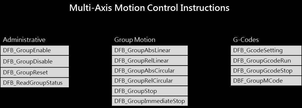

132 _7 AH Motion Controller Operation Manual 7-6
133 Chapter 7 Motion Control Programming 7.4 Axis Parameter Description Axis Type Setting Servo Axis Form Setting Node Address Setting Unit of Display Setting Pulse Count Per Motor Rotation Distance Count Per Motor Rotation Maximum speed setting Start-up speed setting Setting Value Unit Default A real axis which produces actual output to the drive assembly A virtual servo axis on which the operation is done in the controller Linear axis: The position value will be constantly increased (or decreased) when the linear axis rotates toward the positive direction (or negative direction). Rotary axis: The position value will be calculated again from minimum (maximum) value after the axis which rotates toward the positive direction (or negative direction) reaches the limit value. If Real axis is selected in the Axis Type Setting box, the content in Node Address Setting must be chosen by the servo names and station addresses in ECAT Builder. It means that the axis is the set EtherCAT servo drive to which the actual output is delivered. - Virtual servo axis Minimum Value Linear axis Users can select a system unit. - User unit - - Users can set how many pulses the controller outputs for a motor to rotate. Users can set the distance in an actual mechanism move whenever a motor rotates. Users can set the upper limit of the speed of the axis. (the program can be refreshed by using DFB_AxisSetting1 to input the Vmax in the contact) Users can set the start-up speed for the axis to start running. (the program can be refreshed by using DFB_AxisSetting1 to input the Vbias in the contact) Maximum Value Pulse User Unit User Unit/s User Unit/s _ 7-7
134 AH Motion Controller Operation Manual _7 Maximum Acceleration Setting Maximum Deceleration Setting MC_Stop deceleration = 0 Setting Error Deceleration Setting Stop Software Limit Enable Setting Axis positive Setting Axis negative Setting software limit software limit Rotary Maximum Position Setting Rotary Minimum Position Setting Gear Ratio Numerator Gear Ratio Denominator Users can set the upper limit of the acceleration of the axis. (when the contact of the function block is set to 0, it will go maximum acceleration) Users can set the upper limit of the deceleration of the axis. (when the contact of the function block is set to 0, it will go maximum acceleration) When the value is set to 0 in the contact of the function block MC_Stop, the methods to stop are immediate stop and deceleration stop. Immediate Stop: not sending any pulse Deceleration Stop: it will go maximum acceleration until it stops Users can set the axis stopping method, when the axis runs beyond the software limit set. The option Immediate Stop or Deceleration Stop can be selected. Immediate Stop: not sending any pulse Deceleration Stop: it will go maximum acceleration until it stops Users can set whether to enable or disable the software limit control Disabled: disable software limit funciton Enabled: enable software limit funciton (after using the software limit, users can only use the following function blocks MC_MoveAbsolute, MC_MoveRelative, MC_MoveAdditive and MC_MoveVelocity to exit from the limit position) Users can set the positive software limit value of the axis, which is only applied to the linear axis. Users can set the negative software limit value of the axis, which is only applied to the linear axis. Users can set the maximum position of the rotary axis which moves toward the positive direction. The position value will be calculated again from the minimum value after the axis reaches the limit value. Users can set the minimum position of the rotary axis which moves toward the negative direction. The position value will be calculated again from the maximum value after the axis reaches the limit value. Users can set the numerator value of the electronic gear ratio. Users can set the denominator value of the electronic gear ratio. User Unit/s User Unit/s - - Immediate Stop Immediate Stop Disabled - - User Unit User Unit User Unit User Unit
135 Chapter 7 Motion Control Programming Homing Velocity Homing Closed Velocity Permitted Deviation Start single axis immediately MC_CamIn direction of the master axis The parameter is the speed while the homing is performed. While the homing is performed, the motor moves at the homing velocity at first. Then the motor starts to decelerate to this velocity and moves at this velocity when the trigger is close to the home signal. The permitted deviation value for the difference between the actual position and the command position For instance: 0: when executing MC_MoveAbsolute and the actual and command positions are at , the contact of the function block will be Done (true). -1: only the command position will be used, and the actual position will be left unchecked. Note: within the permitted deviation for the following function blocks, MC_MoveAbsolute, MC_MoveRelative, MC_MoveAdditive, DFB_GroupAbsLinear, DFB_GroupRelLinear, DFB_GroupAbsCircular, and DFB_GroupRelCircular, when the actual and command positions are the same, the contact of the function block will be Done (true). Enable: when triggered, it will start the single axis immediately (not affected by the scan time) Disable: after the function block is executed, the single axis will stop when all the programs are scanned by the PLC. Note: it can be used with the following function blocks MC_MoveAbsolute, MC_MoveRelative, and MC_MoveAdditive. Forward: if the direction of the master axis is forward, the slave will follw; while the direction of the slave axis is reverse, the slave will not move along. Not specified: the slave axis will move along with the mater axis whether it s going forward or reversed. 0.1 rpm 0.1 rpm User Unit Disable Forward - - 7_ 7-9
136 AH Motion Controller Operation Manual 7.5 State Transitions This section introduces the state transitions in single axis motion and axes group motion when multiple motion control function blocks are used. The transition rules comply with the PLCopen motion control standard Axis States Note1: Entering ErrorStop state when an error occurs on the axis Note2: Enable of MC_Power changes to False and no axis error occurred. Note3: MC_Reset is executed and Status of MC_Power is False. Note4: MC_Reset is executed and both Enable and Status of MC_Power aretrue. _7 Note5: both Enable and Status of MC_Power change to True. Note6: Done of MC_Stop changes to True, and Execute of MC_Stop. Is False. Note7: when the axis is in Coorrdinated and Execute of MC_Stop changes to Ture, the axis will enter Coordinated Stop ; When the axis is in Coorrdinated Stop and Execute of MC_Stop changes to False, the axis will enter Coordinated. Note8: when the axis is in Coorrdinated and one single-axis motion instruciton is executed on the axis, the axis goup state will enter ErrorStop and the axis will enter Coordinated Halt. When the error is reset by MC_Reset, the axis will resume Coordinated. 7-10
137 Chapter 7 Motion Control Programming Axis Group State 9 Note1: the axis group moves by multi-axis motion control instructions. Note2: entering ErrorStop state when an error occurs on the axis group. Note3: when axis group is enabled, DFB_GroupReset switches the goup state to Standby. Note4: when axis group is not enabled, DFB_GroupReset switches the group state to Disabled. Note5: DFB_GroupDisable swiches the group state to Disabled. Note6: group state changes to Standby when Done of DFB_GroupStop is True and Execute of DFB_GroupStop changes to Fasle. Note7: group state switches to ErrorStop when 1. DFB_GroupDisable executes, 2. group motion executes, or 3. a single-axis motion instruciton is executed in Coordinated state. Note8: group state switches to ErrorStop when 1. DFB_GroupDisable executes, 2. group motion executes, or 3. a single-axis motion instruciton is executed in Coordinated state. Note9: group state switches to ErrorStop when a single-axis motion control instruction is executed in Coordinated state. Note10: group state switches to ErrorStop when an axis in the axis group is not in Standstill, and the following conditions occur: 1. DFB_GroupEnable is executed, 2. Group motion executes, or 3. DFB_GroupStop executes. 7_ 7-11
138 AH Motion Controller Operation Manual 7.6 Buffer Mode During the execution of a motion control instruction, it is possible to execute other motion instructions for the same axis. There are 6 buffer modes for users to choose from, switching from one motion instruction being executed to another motion instruction. The buffer mode can be selected through the BufferMode parameter of the buffered motion instruction.users can select the buffer mode according to the buffer mode of the later instruction. Terms used in the buffer mode are described below: Current motion instruction: the current motion instrtuction for controlling the axis Buffered instruciton: the instruction is waiting to be executed. Transit velocity: the speed at which the axis moves at the moment when the currently being executed instruction is switched to the buffered instruction. Target velocity: the Velocity parameter of an instruction Target position: the Position or Distance parameter of the position-related instructions. Buffer Mode 0: mcaborting (Aborting) 1: mcbuffered (Buffered) 2: mcblendinglow (Blend with low) 3: mcblendingprevious (Blend with previous) 4: mcblendingnext (Blend with next) 5: mcblendinghigh (Blend with high) Description The instruction being executed currently is aborted immediately. The buffered instruction just starts to control the axis after the current instruction execution is completed. The buffered instruction just starts to control the axis after the target position of the current instruction is reached. The transit velocity is the lower of the target velocities of the current instruction and buffered instruction. The buffered instruction just starts to control the axis after the target position of the current instruction is reached. The transit velocity is the target velocity of the current instruction. The buffered instruction just starts to control the axis after the target position of the current instruction is reached. The transit velocity is the target velocity of the buffered instruction. The buffered instruction just starts to control the axis after the target position of the current instruction is reached. The transit velocity is the higher of the target velocities of the current instruction and buffered instruction. _7 7-12
139 Chapter 7 Motion Control Programming Demonstration: Using two MC_MoveRelative instructions for explanation The maximum velocity of the first MC_MoveRelative instruction is V 1 and distance is S 1. The maximum velocity of the second MC_MoveRelative instruction is V 2 and distance is S 2. Modifying the value of BufferMode of the second MC_MoveRelative instruction, you can get different blending processes of the two instructions. See details as below. Buffermode = mcaborting: see the four examples below. 1. Current instruction is aborted while the controlled axis is accelerating. 2. Current instruction is aborted while the controlled axis is moving at a constant velocity. V V V 2 V 2 Curr ent instruction is started The buffer ed instr uction is star ted and then starts to contr ol the axis im mediately. V 1 Current instr uction is s tar ted The buffered i nstruction is s tarted and then starts to control the axis i mmediately. C urrent i nstruction Buffered instruction t Curr ent instruction Buffer ed instruction t 3. Current instruction is aborted while the controlled axis is decelerating. 4. The velocity direction of the buffered instruction is opposite to the current instruction. V V T he buffer ed ins tru cti on is star te d a nd the n sta rts t o contro l the axis im me dia tely. V 2 V 1 Current instr uction is star ted V 1 Curr ent ins truction is started The buffered ins truction is s tarted and then starts to contr ol the axis immediately. C urrent instruc ti on Buffered instruction t Current ins tr uction Buffered instruction t V 2 7_ 7-13
140 AH Motion Controller Operation Manual Buffermode = mcbuffered: see the two examples below. 1. When the direction of the buffered instruction is the same as that of the current instruction 2. When the direction of the buffered instruction is opposite to that of the current instruction. V V 2 V 1 When current i nstruction execution is completed, the buffered i nstruction starts to controlthe axis. The buffered i nstruction is started Cur rent ins truction is s tarted S 1 S2 V V 1 Current ins truc tion i s s tarted Current ins tr uction The buffered instruc tion is s tarted S1 When cur rent ins truction ex ec ution is is c ompl eted, t he buffer ed i nstruction starts to control the axis. Buffered instruction S2 t Curr ent instruction Buffered instruction t V 2 Buffermode = mcblendinglow: see the three examples below. 1. When the velocity of the current instruction is less than that of the buffered instruction. 2. When the velocity of the current instruction is greater than that of the buffered instruction. V V 2 V 1 The buffered i nstruction is started Current instruction is started T he buffered i nstruction starts to control the axis when current instruction executi on is completed and the axis v elocity is the low er of the tw o i nstruction vel ocities. S1 S2 V V 1 The buffered i nstruction is s tarted V 2 Curr ent ins truction S 1 is s tarted T he buffered i nstruc tion s tar ts to control the axi s when cur rent ins truc tion ex ecution is c ompleted and the axis v eloc ity is the low er of the two instruction velocities. S2 Cur rent i nstruction Buffered instruction t Curr ent ins truction Buffered instruction t 3. When the velocity direction of the current instruction is opposite to that of the buffered instruction. V _7 The buffer ed i nstruction is started V 1 C urrent instructi on i s started S1 The moti on di rections of current instruc ti on and buffered ins tr uction ar e oppos ite. The buffered ins truc tion s tarts to control the ax is w hen c urrent ins truction dec elerates till the veloc ity is 0. Buffer ed instruction Current instruction S2 t V
141 Chapter 7 Motion Control Programming Buffermode = mcblendingprevious: see the three examples below. 1. When the target velocity of the current instruction is less than that of the buffered instruction. 2. When the target velocity of the current instruction is greater than that of the buffered instruction. V T he buffer ed ins truction starts to contr ol the axis when curr ent ins truc tion ex ecution is completed and the axis v eloc ity is that of the previous instruction. V The buffered instr uction is star ted T he buffered i nstruction starts to control the axi s when cur rent instr uction executi on is completed and the axi s vel ocity i s that of the pr evious i nstruction. V 2 The buffered i nstruction is s tarted V 1 V 2 V 1 Current ins truc tion is s tarted S1 S2 Current instruction is started S1 S2 Cur rent i ns truction Buffered instruction t C urrent i nstruction Buffered instruction t 3. When the velocity direction of the current instruction is opposite to that of the buffered instruction. V The buffer ed i nstruction is started V 1 C urrent instructi on i s started S1 T he motion direc tions of c urrent ins truction and buffered i nstruc tion are opposite. The buffered ins truc tion s tarts to control the axis w hen current instruc ti on deceler ates til l the veloci ty i s 0. Buffered instruction Current ins truc tion S2 t V 2 Buffermode = mcblendingnext: see the three examples below. 1. When the target velocity of the current instruction is less than that of the buffered instruction V V 2 The buffered instruction is s tarted Current instruction execution is completed and the buffered instr uction starts to control the axi s when the axis accel erates to the v eloc ity of the next instruction. 2. When the target velocity of the current instruction is greater than that of the buffered instruction V V 1 The buffered instructi on i s started Current instruction execution is completed and the buffered instruction starts to control the axis w hen the axis velocity is decreased to the velocity o f the next instruction. 7_ V 1 C urrent i nstruction is s tarted S1 S2 V 2 Cur rent instruction is started S1 S 2 Current instr uction Buffered instruction t Current i nstructi on Buffered instruction t 7-15
142 AH Motion Controller Operation Manual 3. When the velocity direction of the current instruction is opposite to that of the buffered instruction V The buffered i nstruction is s tarted V 1 Current ins truc tion is s tarted S1 T he buffer ed instruction starts to control the axis when the motion dir ections of buffered instruc ti on and curr ent instruc tion are opposite and the velocity of cur rent instr uction is decreased to 0. Buffered instr uction Current instruction S2 t V 2 Buffermode = mcblendinghigh: see the three examples below. 1. When the target velocity of the current instruction is less than that of the buffered instruction 2. When the target velocity of the current instruction is greater than that of the buffered instruction V T he buffer ed ins truction starts to control the axis when current instruc ti on ex ecution is com pleted and the axi s vel ocity r eaches the higher of the two instruction velocities. V The buffered i nstruction is s tarted T he buffered instruction starts to control the axis w hen current i nstruction executi on is completed and the axis v elocity is the higher of the tw o i nstruction vel ocities. V 2 The buffered i nstruction is started V 1 V 1 Current instructi on i s started S1 S2 t V 2 Current instr uction is s tar ted S1 S 2 Current instruc ti on Buffered instruction t Cur rent i nstruction Buffered instruction t 3. When the velocity direction of the current instruction is opposite to that of the buffered instruction V _7 V 1 The buffered instr uction is s tar ted C urrent instructi on i s started S1 T he buffered instructi on star ts to control the axi s when the motion directions of buffered instruction and cur rent instr uction ar e opposite and the velocity of current instruction is decreased to 0. Buffered instruction Curr ent instruction S2 t V
143 Chapter 7 Motion Control Programming Whether the current instruction execution has been completed or not depends on the completion output parameter of the instruction. As the completion output parameter is TRUE, it indicates that the instruction execution is completed and the buffered instruction execution starts. See the completion output parameters of instructions in the following table so as to judge the instruction execution state in a buffer mode. Instruction name Is it a buffered instruction? (Yes or No) Can it be followed by a buffered instruction? (Yes or No) Completion output parameter of an instruction MC_MoveAbsolute Yes Yes Done MC_MoveRelative Yes Yes Done MC_MoveAdditive Yes Yes Done MC_MoveSuperImposed No No MC_MoveVelocity Yes Yes InVelocity MC_Home No Yes Done MC_Stop No Yes Done=True and Execute=False MC_Halt Yes Yes Done MC_TorqueControl Yes Only for MC_TorqueControl/MC_Halt InTorque MC_Power No Yes Status MC_HalfSuperimposed No No MC_CamIn Yes Yes EndOfProfile MC_GearOut No Yes Done MC_GearIn Yes Yes InGear MC_GearOut No Yes Done MC_PhasingAbsolute MC_PhasingRelative MC_VelocityControl Yes Yes Yes Only for MC_PhasingAbsolute/ MC_PhasingRelative Only for MC_PhasingAbsolute/ MC_PhasingRelative Only for MC_VelocityControl/MC_Halt 7.7 Execution of Function Block Instructions Done Done InVelocity 7_ The execution of the motion control instrucitons is controlled by the input parameters, and the status and execution results are indicated on the outputs. This section introduces the definition and function of the common interface of function block instructions The Interface of a Motion Control Function Block Common inputs and outputs in motion control function blocks are listed below. A function block has one or a part of the inputs/outputs listed below. For example, a function block has either the Execute input or the Enable input, based on the properties of the motion control function block. 7-17
144 AH Motion Controller Operation Manual Inputs Name Description Date Type Setting value (Default) En* Receiving the logic state in front of this instruction. BOOL True/False (False) Enable Enabling the motion control function block BOOL True/False (False) Execute Starting the motion control function block BOOL True/False (False) Outputs Name Description Date Type Setting value Eno* Transfering the logic state of the En input to the following instruction which is connected in series BOOL True/False (False) Done The execution of the function block is complete. BOOL True/False (False) Valid An output value is valid. BOOL True/False (False) Busy The motion control function block is being executed. BOOL True/False (False) Active True when the axis is being controlled. BOOL True/False (False) Command Aborted(Ab orted) The execution of the motion control function block is interrupted by another instruction. BOOL True/False (False) Error An error occurs in a function block. BOOL True/False (False) *Note: The function of En/Eno is to receive or transfer the logic state in the program, and will not be included in the details of the inputs/outputs of each motion control instruction. _7 A motion control function block has either the Execute input or the Enable input. The Execute/Enable input in a motion control function block is used to start the motion control function block. A motion control function block generally has the Busy output and the Done output. The Busy output and the Done output indicate the state of the motion control function block. If the execution of motion control function block is to be interrupted by another motion control function block, the CommandAborted/Aborted output will be added to the motion control function block. Besides, the Error output is used to indicate that an error occurs when the motion control function block is executed. A motion control function block has not only the Execute/Enable input, but also value/state inputs. The characteristics of the value/state inputs are described below. - Use of input values: If the input that a motion control function block has is the Execute input, values are used when there is a transition in the Execute input s signal from low to high. If a new value is created, it becomes valid when the Execute input is triggered again while the instruction is not in busy status. If the input that a motion control function block has is the Enable input, values are used when there is a transition in the Enable input s signal from low to high. Compared with the Execute input, the Enable input is used more often when an input value is updated repeatedly. 7-18
145 Chapter 7 Motion Control Programming - An input value exceeds a range. After a motion control function block is started, the input values which are not in ranges allowed will be limited, or result in an error occurring in the motion control function block. If an error occurring in a motion control function block results in an error occurring in an axis, the motion control function block is applied incorrectly. You should prevent incorrect values from being generated in an applied program. - Outputs are mutually exclusive. If the a motion control function block has an Execute input which is set to True, either the Busy output, the Done output, the CommandAborted /Aborted output, or the Error output can be set to True. If the a motion control function block has an Enable input, the Valid output and the Error output are mutually exclusive, and only the Valid output or the Error output can be set to True. - Time when output data/states are valid If the input that a motion control function block has is the Execute input, the Done output, the Error output, the CommandAborted output, and data output are reset when there is a transition in the Execute input s signal from high to low, but the execution of the function block does not stop when there is a transition in the Execute input s signal from high to low. Even if the Execute input in a motion control function block is reset before the execution of the motion control function block is complete, output states will still be generated and retained for one cycle. If a motion control function block is started again before the execution of the motion control function block is complete, the motion control function block will not give feedback to the Done output and the CommandAborted output, and an error will occur. If the input that a motion control function block has is the Enable input, the Valid output, the Busy output, and the Error output are reset when there is a transition in the Enable input s signal from high to low. (MC_Power has different behaviors on the inputs and outputs, refer to MC_Power for details.) - Characteristic of the Done output The Done output in a motion control function block will be set to True after the motion control function block is executed successfully. - Characteristic of the Busy output If the input that a motion control function block has is the Execute input, the motion control function block uses the Busy output to indicate that the execution of the motion control function block is not complete, and new output states (values) are expected to be generated. The Busy output is set to True when there is a transition in the Execute input s signal from low to high. When the Done output, the CommandAborted output, and the Error output are set to True, the Busy output are reset. If the input that a motion control function block has is the Enable input, the motion control function block uses the Busy output to indicate that the execution of the motion control function block is not complete, and new output states (values) are expected to be generated. The Busy output in a motion control function block is set to True when there is a transition in the Enable input s signal from low to high, and is set to True when the motion control function block is executed. When the Busy output is set to True, output states (values) still change. - Characteristic of the CommandAborted output 7_ The CommandAborted output in a motion control function block is set to True when the execution of the motion control function block is interrupted by a command. - Relation between the Enable input and the Valid output If the input that a motion control function block has is the Enable input, the motion control function block uses the Valid output to indicate whether output data/states are valid. The Valid output is set to True only when the Enable input is set to true and output data/state are valid. If an error occurs in a motion control function block, output data/states will 7-19


146 AH Motion Controller Operation Manual not be valid, and the Valid output will be set to False. The Valid output in a motion control function block will not be True until the error occurring in the motion control function block is eliminated, and output data/states become valid Timing Diagram for Input/Outputs Situation 1: The execution of the motion control function block is interrupted. Situation 2: An error occurs in the motion control function block. Situation 3: The execution of the motion control function block is complete normally. Situation 1: The motion control function block is executed normally. _7 Situation 2: An error occurs in the motion control function block. 7-20
147 Chapter 7 Motion Control Programming 7.8 Positions This section describes the positions that are used in motion control programming Postion Types Position Type Command position Actual position Description The command position is the position value that the Motion CPU outputs to drive an axis. The actual position is the position feedback value from the servo drive or the encoder. The valid positions for each axis type are listed as below Applicable Postions for Each Axis Type Axis type Position Type Command Position Actual Position Servo axis Valid Valid Vertual axis Valid Valid* *Note: the command position and the actual position is the same on virtual axis. 7.9 Electronic Cam This section introduces the operation of electronic cam (e-cam), and the steps to applied e-cam by settings in the software and the motion control instructions related to e-cam. For details about each mentioned instruction, please refer to AH Motion Controller Motion Control Instructions Manual Introduction of Electronic Cams A traditional mechanical cam is composed of a cam, a follower, and a support. 1. A mechanical cam is a rotating sliding piece with irregular shape. In general, it is an input object which rotates at a uniform speed. It makes a follower move regularly by coming into contact with the follower. 2. A follower is a part driven by a mechanical cam. In general, it is an output object which generates motion which is not uniform, sequential, and regular motion. 3. A support is a piece that which is used to support a mechanical cam and a follower. 7_ 7-21
148 AH Motion Controller Operation Manual Compared with a traditional cam, an electronic cam has the following advantages. 1. Friendlier user interface 2. Different products require different cam curves. Users can modify the electronic cam data in an electronic cam in software. Users do not need to modify the mechanical design. 3. High acceleration 4. Smoother operation Operation of an Electronic Cam _7 7-22
149 Chapter 7 Motion Control Programming Step 1 Step 2 Step 3 Initial setting Setting a master axis and a slave axis Starting/Stopping an electronic cam Creating electronic cam data (1) Setting an input pulse type (2) Setting a master axis (3) Setting the starting angle of the master axis specified (3) Setting a slave axis (3) Starting/Stopping a cam which operates cyclically (3) Initial Setting Creating Electronic Cam Data There are two methods of creating electronic cam data. Method 1: Function that relates the positions of a master axis to the positions of a slave axis Method 2: Measuring the relation between the positions of a master axis and the positions of a slave axis at work Please refer to section for more information. Setting an Input/Output Pulse Type 1. Setting an input pulse type The master axis specified can be a manual pulse generator, a motion axis, AC0, AC4, AC8, AC12, AC16, or AC20. If you use a counter as a master axis, you have to set an input pulse type. You can set an input pulse type for the counter used by means of the motion control function block DFB_HCnt. 2. Value of InputType Input value Input type (positive logic) Description mcud (0) FP Clockwise pulses RP Counterclockwise pulses Counting up/down 7_ mcpd (1) FP Pulses RP Directions Clockwise Counterclockwise Pulses+Directions FP A-phase pulses mcab (2) RP B-phas e pulses A/B-phase pulses Clockwise Counterclockwise 7-23
150 AH Motion Controller Operation Manual mc4ab (3) FP A-phase pulses RP B- phase pulses Clockwise Counterclockwise Quadruple frequency of A/B-phase pulses Setting a Master/Slave Axis and Operating an Electronic Cam You can set a master axis and a slave axis, and operate an electronic cam by MC_CamIn. After the setting of the inputs in the motion control function block MC_CamIn is complete, the instruction will be enabled if Enable is set to True. The outputs in the motion function block MC_CamIn can be used to monitor the electronic cam motion. _7 7-24
151 Chapter 7 Motion Control Programming Setting a Master Axis You can set a master axis by Master in the motion control function block MC_CamIn. Value of the Master Input value Definition Description A motion axis 1~n is used as a master axis (AH08EMC: n=8, 1~n Motion axis AH10EMC: n=16, AH20EMC: n=32) 200 Counter The counter AC00 is used as a master axis. 7_ 204 Counter The counter AC04 is used as a master axis. 208 Counter The counter AC08 is used as a master axis. 212 Counter The counter AC12 is used as a master axis. 216 Counter The counter AC16 is used as a master axis. 220 Counter The counter AC20 is used as a master axis. 7-25
152 AH Motion Controller Operation Manual Setting the Starting Engaging Position of a Master Axis You can set the starting engaging position of the master axis specified by ActivationPosition in the motion control function block MC_CamIn. Value of the ActivationPosition Input value Definition Description _7 Negative number, positive number and 0 starting engaging position of the master axis specified Specify the position of the master axis as the engagement begins. In other words, when the master axis passes the position, the slave axis starts to perform the engagement action. 7-26
153 7_ Chapter 7 Motion Control Programming 7-27
154 AH Motion Controller Operation Manual Setting a Slave Axis You can set a slave axis by Slave in the motion control function block MC_CamIn. Value of Slave Input value (Default value) Definition Description K1~Kn* (0) Motion axis number The motion axis that is used as a slave axis. _7 *Note: Kn refers to the maximum supported axes of different models. For example, AH20EMC-5A supports K1~K Starting/Stopping an Electronic Cam Operating Cyclically If an electronic cam operates cyclically, the slave axis of the electronic cam moves in accordance with electronic cam data when the master axis of the electronic cam moves. Electronic cam data defines only one cycle. The relation between the positions of a master axis and the positions of a slave axis is the repeated extension of electronic cam data. 7-28

155 Chapter 7 Motion Control Programming Electronic cam data Slave axis Max =180(Unit) Master axis Max =360(Unit) Starting a Cyclic Electronic Cam Operation After you set a master axis, a slave axis, and a starting angle by means of inputs in the motion control function block MC_CamIn, electronic cam motion will be started if the Enable is set to True and the Periodic is set to Ture. 7_ 7-29
156 AH Motion Controller Operation Manual Value of the EndofProfile Output value Definition Description True/False Starting a cam cycle Indicates the end point of the cam profile is completed. (Resets automatically) The steps of starting an electronic cam which operates cyclically are as follows. At the time T1, Enable is set to True (an electronic cam which operates cyclically is started). After the time T2 elapses, EndofProfile will be set to True. EndofProfile will be reset after one scan cycle. During the time T3, the initialization of the electronic cam is complete, the electronic cam operates cyclically, and the motion of the slave axis specified follows the motion of the master axis specified in accordance with the electronic cam data created. n n+60 n+300 Displacement of the slave axis Starting an electronic cam operating cyclically ( Enable) Position of the master axis EndofProfile T1 T2 Reset automatically T3 Stopping a Cyclic Electronic Cam Operation You can stop an electronic cam by CamOut in the motion control function block MC_CamIn. _7 1. Value of Execute Input value Definition Description True/False 2. Value of Done Not engaging with the master axis specified If CamOut is set to True, the slave axis specified will not engage with the master axis specified. Output value Definition Description True/False Disable the slave axis specified engaging with the master axis specified. If the engagement of the slave axis specified and the master axis specified is done, the output pin will be set to True. 7-30

157 Chapter 7 Motion Control Programming Creating Electronic Cam Data Electronic cam data defines the relation between the positions of a master axis and the positions of a slave axis. Before you create a cam chart in ISPSoft, you have to know the relation between the positions of a master axis and the position a slave axis. There are two methods of getting the relation between the positions of a master axis and the positions of a slave axis. Method 1: Creating master/slave relation by setting E-CAM data Method 2: Importing the recorded E-CAM data with master/slave relation to create the E-CAM curves After electronic cam data defines the relation between the master/slave positions, you can get the positions of the slave axis by means of the positions of the master axis Creating a CAM Chart in ISPSoft Creating master/slave relation by setting E-CAM data After you create a project in ISPSoft, right-click E-CAM Editor in the system information area, and click NEW, the New E-CAM-Chart window will appear. Set the parameters in the New E-CAM-Chart window, and then click OK, An E-CAM data item under E-CAM Editor will appear in the system information area. The below steps are the procedures for setting up parameters for the new E-CAM chart. Type an E-CAM name in the Name box. Type an E-CAM ID in the Item ID box. E-CAM ID ranges from 1 to 32. If you want to set an E-CAM password, you have to type the same password in the two boxes. You can only type English letters, numerical digits. When the E-CAM is opened next time, the password will be requested. If Show Charact checkbox is selected, the input characters for the password will be displayed. 7_ 7-31


158 AH Motion Controller Operation Manual After the parameters are set, click OK and the E-CAM editing window will be displayed as below. E-CAM curve area: the E-CAM curves of position, velocity and acceleration are established according to the specified data in the Data setting area. You can modify the curves by moving the data points directly in the E-CAM chart, or insert data points or sections by using function buttons. Data setting area: By using function buttons, you can create or delete data points or sections and modify the curves by specifying the data points in the Data setting area. The changes in the data settings area will be synchronized to the E-CAM curve area. After the E-CAM item is created, you can right-click on the item and select Delete to delete this item, or select Property to change the name and password of this E-CAM item. Note that Item ID is not allowed to be changed. Refer to the diagram below. _7 7-32
159 Chapter 7 Motion Control Programming Function buttons for E-CAM chart: Icon Name Description Insert a point Insert a section E-CAM setting Export Import Inserting an data point to the position curve in the E-CAM curve area Inserting a section with two end points into the position curve in the E-CAM curve area Opening the E-CAM setting window Exporting the E-CAM data in.txt format and speicifying the directory for saving this file. Importing the E-CAM file from the specified directory Insert a row Inserting a row under the selected row in the Data setting area Delete a row Deleting a selected row in the Data setting area. The operation and setting steps by using the function buttons are explained as below. You can click (Insert a point) and move the cursor to the position where you want to create a data point. Click at the position to create the data point, and the position/velocity/acceleration data of the data point will also be inserted in the Data setting area as below. 7_ 7-33

160 _7 AH Motion Controller Operation Manual 7-34

161 Chapter 7 Motion Control Programming 1. You can click (Insert a section) and move the cursor to the position where you want to insert a section. Click at the data point to create the section, and the position/velocity/acceleration data of the two end points of the section will also be inserted in the Data setting area as below. 7_ 7-35
 3.")
162 AH Motion Controller Operation Manual 2. Click (Setting) to open the setting window for the current E-CAM chart. Master position: defines the display range of the master axis in the E-CAM curve area. Slave position: defines the display range of the slave axis in the E-CAM curve area. Resolution: defines the resolution of this E-CAM chart (max.: 2047) 3. You can click (Insert a row) or (delete a row) to edit the Data setting area. Modifying the master/slave position in the table ill change the E-CAM curve in the E-CAM curve area immediately. _7 7-36
, and the E-CAM cycle will operate according to the designed E-CAM curves.")
163 Chapter 7 Motion Control Programming In the Data setting area, each column in the table can be specified to define the parameters of the data points which are listed in rows. The whole E-CAM curve are constructed by these data points (max. 20 rows), and the E-CAM cycle will operate according to the designed E-CAM curves. The columns in the Data setting area are explained as below. Master position: the master position of the data point Slave position: the slave position of the data point Slave velocity: the slave velocity calculated automatically according to the specified position. Slave acceleration: the slave acceleration calculated automatically according to the specified position. CAM Curve: the cam curve type between the data points, including Const Speed, Const Acc., Single Hypot., Cycloid and B-Spline. Resolution: the resolution of current section. The resolution setting should be specified according to the equipment requirements. The equipment operates smoother with a higher resolution, however the E-CAM data size also grows bigger with higher resolution. After the E-CAM editing is completed, you can use CamTable of MC_CamIn to specify the Name or the Item ID of the E-CAM chart. The specified E-CAM chart will be applied in the E-CAM operation when the two instructions are enabled or executed. For detailed explanations of the two instructions, refer to AH Motion Controller Motion Control Instructions Manual 7_ Importing the Recorded E-CAM Data with Master/slave Relation to Create the E-CAM Curves You can store the master/slave positions in a file, and then import the relation into a cam chart in ISPSoft. The steps of importing the E-CAM data into a cam chart in ISPSoft are as follows. 7-37

164 AH Motion Controller Operation Manual 1. Record and save the CAM data in CAM_1.txt. 2. Open an E-CAM Chart window in ISPSoft. _7 7-38

165 Chapter 7 Motion Control Programming 3. After is clicked, select the file CAM_1.txt to import the recorded CAM data. Click Open, and the E-CAM curves will be drawn on the E-CAM Chart as below. Modifying the E-CAM Data Directly in the Program After you create electronic cam data in a cam chart in ISPSoft, the cam data will be downloaded to an AH Motion Controller CPU. If you modify the electronic cam data in ISPSoft, you have to download the new electronic cam data created to the AH Motion Controller CPU again after you modify the electronic cam data. If you want to modify the electronic cam data in the program, you can use function block instructions. DFB_CamMultiRead is used to read a particular point in a cam chart, and DFB_CamMultiWrite is used to modify a particular point in a cam chart. 7_ 7-39
166 AH Motion Controller Operation Manual Application of an Electronic Cam Using a Rotary Cutter In the application of cutting materials on a feeding belt, a traditional approach is that a cutting roller will rotate after a feeding roller rotates for a certain length, and the alternation of feeding materials and cutting the materials is repeated. The disadvantage of this approach is that the acceleration/deceleration needed in order for a feeding roller to rotate/stop decreases production efficiency. As a result, a new approach is that materials are fed continuously. There are two ways of cutting materials on a feeding belt: rotary cut and flying shear. Flying shear is reciprocating motion, while rotary cut is unidirectional motion. The cam curve for rotary cut is different from the cam curve for flying shear. The application of rotary cut is described below. 4 Servo Length of the cutting AH M otio n CP U Servo Output of the encoder CAM X ax is Jog Y ax is Concept 1. In the application of rotary cut, the cutting roller of a rotary cutter rotates in a direction. A material is cut when the blade of the rotary cutter comes into contact with the material. The feeding roller of the rotary cutter continuously feeds materials at a uniform speed. The relation between rotary cut and the output generated is shown below. At first, the slave axis accelerates until it moves to the synchronization zone. After the slave axis leaves the synchronization zone, it decelerates until it returns home. A cycle is complete when the slave axis is at home. You can draw a speed relation chart. _7 7-40
167 Chapter 7 Motion Control Programming Home 1 Cutting axis (Slave axis) 3 Feeding axis (master axis) 2 Synchronization zone (Cutting zone) V Equal to the speed of the master axis Acceleration Synchronization Deceleration Distance for which the master axis moves (Length of a cutting) T 2. During the processing of cutting materials, synchronization is an important factor. When the bladed of a rotary cutter come into contact with a material, the speed of the blade must be the same as the speed of the material. If the speed of the blade of a rotary cutter is greater than the speed of a material when it comes into contact with the material, the force which pulls the material forward will appear, and the material will be cut smoothly. If the speed of the blade of a rotary cutter is less than the speed of a material when it comes into contact with the material, the material will be jammed. 3. The design of a synchronization zone affects the operation of equipment. The bigger the synchronization zone is in a cycle, the less time it takes for the slave axis specified to accelerate/decelerate. If equipment needs to accelerate/decelerate in a short time, there will be a great impact on the electric machinery used and the blade used, and there will be an overcurrent passing through the servo used. 4. Relation between the length of a cutting and the circumference of a blade Length of a cutting<length of the blade used: The speed of cutting roller used is the same as the speed of the feeding roller used in the synchronization zone designed. After the cutting roller used leaves the synchronization zone, the cutting roller will accelerate. 7_ Ratio of the speed of the slave axis to the speed of the master axis Synchronization zone Position of the master axis 7-41
168 AH Motion Controller Operation Manual Length of a cutting=circumference of the blade used: The cutting roller used rotates at a uniform speed. Ratio of the speed of the slave axis to the speed of the master axis 1 Position of the master axis One time the circumference of the blade used<length of a cutting<two times the circumference of the blade used: After the cutting roller used completes cutting in the synchronization zone designed, it will decelerate, and then accelerate until its speed is the same the speed of the feeding roller used. Ratio of the speed of the slave axis to the speed of the master axis Synchronization zone Position of the master axis Length of a cutting>two times the circumference of the blade used: The length of a cutting is greater than two times the circumference of the blade. (It is a common situation.) After the blade used completes cutting in a cycle, it will decelerate until it stops. After a material of a certain length is fed, the blade used will start cutting again. Ratio of the speed of the slave axis to the speed of the master axis Synchronization zone Position of the master axis _7 7-42

169 Chapter 7 Motion Control Programming Creating Rotary Cut Data You can create a rotary cut E-CAM curve by means of the motion control function block DFB_CamCurve2 and DFBCamCurveUpdate2. Function Block DFB_CamCurve2 1. Creating a cam chart: You have to create a blank cam chart in ISPSoft, and then set resolution in accordance with the number of rotary cut curves. In order to create a rotary cut curve, you need to type 300 in the Resolution box. Download the cam chart to an AH Motion Controller CPU. When the AH Motion Controller CPU operates, electronic cam data is stored in the cam chart. 2. Setting DFB_CamCurve2: You have to set the parameters related to a rotary cutter, including the distance for which the master axis specified moves, the distance for which the slave axis specified is synchronized with the master axis specified, and the synchronization ratio of the speed of the slave axis specified to the speed of the master axis specified. After the motion control function block DFB_CamCurve2 is executed, a rotary cut curve will be created. 7_ 7-43
170 AH Motion Controller Operation Manual Inputs Name Function Data type Setting value (Default value) Timing for updating Execute Executes the instruction to create the cam curve BOOL True/False (False) - MLength_P Specifies the moving distance for master axis. DWORD K1~K2,147,483,647 (0) When Execute shifts to True and Busy is Fasle. SLength_P Specifies the moving distance for slave axis. DWORD K1~K2,147,483,647 (0) When Execute shifts to True and Busy is Fasle. SSyncLength_P Specifes the synchronized distance for the slave axis. DWORD K1~K2,147,483,647 (0) When Execute shifts to True and Busy is Fasle. SSyncRatio Specifies the synchronization ratio between master and slave axes. REAL x10-38 ~ x10+38 (0) When Execute shifts to True and Busy is Fasle. SMaxRatio Specifies the max. cam synchronization ratio between master and slave axes. REAL x10-38 ~ x10+38 (0) When Execute shifts to True and Busy is Fasle. AccCurve* 1 Selects the acceleration curve in the cam profile. WORD 0~3 (0) When Execute shifts to True and Busy is Fasle. ecamcurve* 2 Selects the cam curve type. WORD 0~9 (0) When Execute shifts to True and Busy is Fasle. Defines if reciprocal operation Concatenate is required. True: periodical False; non-periodical BOOL True/False (False) When Execute shifts to True and Busy is Fasle. _7 *Note: 1. Set value of AccCurve. Refer to Function of this instruction for the cam profiles of each acceleration curve. Value Definition 0 Constant speed 1 Const Acceleration 2 SingleHypot 3 Cycloid 2. Set value of ecamcurve. Refer to Function of this instruction for the cam profiles of each type. Value Definition 0 leftcam 1 midcamall 2 midcambegin 7-44
171 Chapter 7 Motion Control Programming 3 midcamend 4 rightcam 5 rightcam 7 midcambegin 8 midcamend 9 Empty Outputs Name Function Data type Output range (Default value) Done True when the cam curve is established. BOOL True/False (False) Busy True when the instruction is executed. BOOL True/False (False) Error True if an error occurs. BOOL True/False (False) ErrorID SyncBegin SyncEnd Indicates the error code if an error occurs. Refer to Appendices for error code descriptions. Records the beginning position of the Synchronization zone Records the ending position of the Synchronization zone DWORD 0x0000, 0x3100, 0x3101, 0x3102 (0) DWORD K0~K2,147,483,647 (0) DWORD K0~K2,147,483,647 (0) In-Outs Name Function Data type Setting value (Default value) Timing for updating Slave Slave axis number WORD K1~K32 (0) When Enable is rising edge triggered and Busy is False. 7_ 7-45


172 AH Motion Controller Operation Manual Function AccCurve 0: Const speed 1: Constant Acceleration 2: SingleHypot 3: Cycloid _7 7-46


173 Chapter 7 Motion Control Programming ecamcurve 0: leftcam 1: midcamall 2: midcambegin 3: midcamend 5: right CAM 7: midcambegin 8: midcamend 9: Empty Example 7_ The parameters of creating a rotary cut curve by means of the motion control function block DFB_CamCurve2 are described below. Distance for which the master axis specified moves=1000 Distance for which the slave axis specified moves=500 Distance for which the slave axis specified is synchronized with the master axis specified=300 Synchronization ratio of the speed of the slave axis specified to the speed of the master axis specified=1.0 The rotary cut curve created and the values of parameters are shown below. 7-47
174 AH Motion Controller Operation Manual Displacement Distance for which the slave axis specified moves: ,000 Angle Vel oc ity Distance for which the master axis specified moves:1,000 Distance for which the axis specified is synchronized with the master axis specified:300 Synchronization ratio of the speed of the slave axis specified to the speed of the master axis specified: ,000 Angle Parameter Setting value Distance for which the master axis specified moves 1000 Distance for which the slave axis specified moves 500 Distance for which the slave axis specified is synchronized with the master axis specified 300 Synchronization ratio of the speed of the slave axis specified to the speed of the master axis specified 1.0 Maximum ratio of the speed of the slave axis specified to the speed of the master axis specified 10.0 Acceleration curve 0 Cam curve 0 Concatenation 0 Steps Download the program created to an AH Motion Controller CPU, and then execute the program. After M1 is set to True, a rotary cut curve will be created. _7 Program in ISPSoft 7-48

175 7_ Chapter 7 Motion Control Programming 7-49
176 AH Motion Controller Operation Manual Function Block DFB_CamCurveUpdate2 After DFB_CamCurve2 is executed, DFB_CamCurveUpdate2 can be used. If you want to modify a rotary cut curve, you can create a new rotary cut curve by DFB_CamCurve2, and then update the rotary cut curve by DFB_CamCurveUpdate2. Inputs Name Function Data type Setting value (Default value) Timing for updating Execute Executes the instruction to update the cam profile. BOOL True/False (False) - Outputs Name Function Data type Output range (Default value) Done True when the cam curve is established. BOOL True/False (False) Busy True when the instruction is executed. BOOL True/False (False) Error True if an error occurs. BOOL True/False (False) ErrorID Indicates the error code if an error occurs. Refer to Appendices for error code descriptions. DWORD 0x0000, 0x3100, 0x3101, 0x3102 (0) _7 7-50
177 8 Chapter 8 Memory Card Table of Contents 8.1 Overview of Memory Cards Appearances of Memory Cards Specifications for SD Cards Using a Memory Card Formatting a Memory Card Installing and Removing a Memory Card SD Slot in a CPU Installing a Memory Card Removing a Memory Card Contents of a Memory Card Initializing a Memory Card Folder Structure in a Memory Card Reading/Writing a Memory Card Backing up the System Restoring the System CARD Utility Backup Restoration


178 AH Motion Controller Operation Manual 8.1 Overview of Memory Cards The AH Motion Controller CPU supports Micro SD cards. Users can purchase products which meet specifications. The specifications for the SD cards supported by the AH Motion Controller CPUs, and the usage of the SD cards are described in this chapter Appearances of Memory Cards SD cards are classified into three types according to size. They are SD cards, minisd cards, and microsd cards. The AH Motion Controller CPU supports Micro SD cards. MicroSD SD MiniSD Specifications for SD Cards There are several specifications for SD cards on the market. SD cards not only can be classified according to size, but also can be classified into three types according to capacity. These types are SD cards, SDHC cards, and SDXC cards. The AH Motion Controller CPU presently support SD and SDHC specifications with micro size. The following is the table of SD card families. Be sure to purchase products which meet the specifications. The SD card families Type SD SDHC SDXC Capacity 2GB Max. 4GB ~ 32GB 32GB ~ 2TB File system FAT/FAT32 FAT32 exfat Size SD Micro SD SDHC Mini SDHC Micro SDHC SDXC Micro SDXC _8 Speed class rating N/A Class 2 (Min. 2 MB/sec.) Class 4 (Min. 4 MB/sec.) Class 6 (Min. 6 MB/sec.) Class 10 (Min. 10 MB/sec.) Class 2 (Min. 2 MB/sec.) Class 4 (Min. 4 MB/sec.) Class 6 (Min. 6 MB/sec.) Class 10 (Min. 10 MB/sec.) 8-2


179 Chapter 8 Memory Card 8.2 Using a Memory Card Formatting a Memory Card A memory card that you use for the first time may not yet be formatted. The memory card which is not formatted can not be used in an AH Motion Controller CPU. Therefore, you need to format the memory card. The file system with which the memory card is formatted is FAT(FAT16)/FAT32. The following example introduces the most common way to format an SD card, that is, formatting an SD card through a card reader. However, you still need to read the documents provided by the SD card manufacturer carefully. If a memory card is formatted, all the data in the memory card will be deleted. You have to check whether the data in a memory card needs to be backed up before you format the memory card. (1) When using MicroSD to SD card adapter,slide the write protect tab on the left side of the memory card upward, and then insert it into a card reader. The operating system detects a new storage device. Slide the write protect tab upward. New storage device (2) Right-click the new storage device and then click Format. Click Format. 8_ 8-3


 After OK in the warning window is")
180 AH Motion Controller Operation Manual (3) The file system with which the memory card is formatted must be FAT. The other default setting is retained. Click Quick Format, and then click Start. (4) After OK in the warning window is clicked, the SD card is formatted. _8 8-4
181 Chapter 8 Memory Card 8.3 Installing and Removing a Memory Card SD Slot in a CPU As shown below, the SD slot is in the middle right area of the front of a CPU. 8_ 8-5
182 AH Motion Controller Operation Manual Installing a Memory Card Insert a memory card into the SD slot in a CPU, and push it downward until it clicks. After the memory card is installed, it is fixed firmly in the slot. If the memory card is loose, it is not installed correctly. Besides, the memory card has anti-misinsertion design. If it is inserted in the wrong direction, it can not be pushed downward. To prevent the CPU from being damaged, you can not force the memory card in. The correct way to insert the memory card is shown below Removing a Memory Card After a memory card is pushed downward, the slot will eject the SD card and you can take it out. _8 8-6
183 Chapter 8 Memory Card 8.4 Contents of a Memory Card Initializing a Memory Card The system initializes the SD card when power is supplied to a CPU or stop to run Folder Structure in a Memory Card The default folder group used by an AH system is shown below. The folder name is AH500, which includes AH500 series CPUs and AH Motion Controller CPUs. Several subfolders are contained inside the AH500 folder. Related files created by users and the AH system are stored in the subfolders. Root directory PLC CARD AH500 Firmware Log SysDup DevMem GCode UserProg File Folder Description Firmware Firmware file (.lzm) Log Error log file (.log) SysDup UserProg GCode FTP DevMem, Setup System backup files (.dup) File memory created by instructions (.txt /.dmd /.csv) External G-code file (100.nc~227.nc) As an external SD card for G-code file (300.nc~400.nc) Reserved 8_ 8-7
184 AH Motion Controller Operation Manual 8.5 Reading/Writing a Memory Card You can read/write data into/from a memory card to back up and update a system by means of the DIP switch on a CPU Backing up the System When a system backup is executed, the user program (including G-code, E-CAM..), the parameter setting, the hardware configuration, the network (e.g. EtherCAT) configuration, and the values on the device memories in a CPU are backed up and saved as a file called AUTOEXEC.dup, which is stored in a folder named SysDup in a memory card. If a default path denotes an existing backup file, the previous data in the old backup file is overwritten when a system is backed up. A system backup can be executed, whether a CPU runs or stops. Please refer to Section 8.7 Backup for the system backup procedure Restoring the System Before a system restoration is executed, you have to make sure that the backup file AUTOEXEC.dup is stored in a folder named SysDup in a memory card. After the system restoration is executed, the user program, the parameter setting, the hardware configuration, and the network configuration in the memory card are restored to a CPU. In addition, if the data in the backup file includes the values on the device memories, the data restored to the CPU will include the values on the device memories. If :/PLC CARD/AH500/SysDup/AUTOEXEC.dup is valid, the CPU will restore the system automatically after power-on.please be sure not to put this file in SD card if you don t want to restore the system.you can restore the system by using Card Utility.Please refer to Section 8.9 Restoration. 8.6 CARD Utility There is a microsd slot on AH Motion Controller CPUs. You can back up/restore data in an AH Motion Controller CPU through the use of a memory card. Besides, ISPSoft provides CARD Utility for AH Motion Controller CPUs. You can back up/restore data in an AH Motion Controller CPU or an ISPSoft project through CARD Utility. The program code, the parameter setting, the hardware configuration, and the network configuration in an AH Motion Controller CPU or an ISPSoft project can be backed up. The values in the devices in an AH Motion Controller CPU can also be backed up. Please refer to previous sections or the AH Motion Controller - Hardware Manual for more information about the specifications of the SD cards which can be inserted into AH Motion Controller CPUs, and the usage of the SD cards. The network configuration stored in an AH Motion Controller CPU is the data which is only related to the AH Motion Controller CPU itself. When you back up the network configuration, only the part of the network configuration which is related to the selected AH Motion Controller CPU will be backed up. The part of the network configuration backed up consists of only a routing table and data exchange data. Therefore, if you restore the backup data to an ISPSoft project, the system will not be able to restore the complete data in the NWCONFIG settings. The functions supported by CARD Utility are described below. The diagram below is a flowchart. _8 If you export data in an AH Motion Controller CPU as a backup file (*.dup), the data exported can be saved in the memory card inserted in the AH Motion Controller CPU, or a folder in the computer. You can decide whether to include the values in the devices in the AH Motion Controller CPU. If you export an ISPSoft project as a backup file (*.dup), the ISPSoft project exported can only be saved in a folder in the computer, and the values in the devices in the AH Motion Controller CPU are not backed up. You can restore the backup file (*.dup) in the inserted memory card to the CPU. You can restore the backup file (*.dup) in a computer to the CPU which is connected, or restore the backup file to an 8-8


185 Chapter 8 Memory Card ISPSoft project. If you choose to restore the backup file to an ISPSoft project, the system will automatically skip the values in the devices and the network configuration in the backup file. After you double-click CARD Utility in the project management area, the system will open the CARD Utility window. 8_ 8-9
186 AH Motion Controller Operation Manual 8.7 Backup If the backup source/backup destination is an AH Motion Controller CPU or the memory card inserted in an AH Motion Controller CPU, you have to make sure that ISPSoft is connected to the AH Motion Controller CPU normally. Please refer to ISPSoft User Manual for more information about the checking operation. (1) Select the Backup (To DUP File) option button in the CARD Utility window, and then click Next. _8 (2) Select a backup source, and then click Next. After you select the ISP Project (Compiled and saved) option button, you have to click, and select an isp file in the Open window. If the program in the isp file selected is not compiled, a message appears when the isp file is backed up. Open the isp file with ISPSoft, compile the program in the isp file, and save the isp file. After the program in the isp file is compiled, you can back up the isp file. 8-10
 Select a backup destination. If the backup source is an ISPSoft project, the backup destination must be a computer. a. If the Memory Card (PLC Side) button is selected, the filename of the backup file which will be produced will be AUTOEXEC.")
187 Chapter 8 Memory Card (3) After you select the CPU (Need Connection) option button, you have to decide whether to include the values in the devices in the AH Motion Controller CPU which is connected to ISPSoft. (4) Select a backup destination. If the backup source is an ISPSoft project, the backup destination must be a computer. a. If the Memory Card (PLC Side) button is selected, the filename of the backup file which will be produced will be AUTOEXEC.dup, and the path which points to the backup file will be Root directory of the memory card\ah500\sysdup\autoexec.dup. 8_ b. If the PC (DUP File) option button is selected, you have to click, and specify the directoty and file name for the backup file. 8-11
188 AH Motion Controller Operation Manual (5) After a backup destination is specified, you can set passwords for the backup file. You can either select Same with Project passswrod or specify a new password by clicking Setting New PLC Password. _8 8-12

189 Chapter 8 Memory Card (6) After you make sure that the summary in the CARD Utility window is consistent with the desired data backup operation, you can click Execute. If you clicked Cancel to stop ISPSoft from backing up data from the CPU to the memory card, the CPU will be still in data backup process. You can power off the CPU to force stop the process. However, the backup file produced is not a complete backup file. As a result, you have to delete the backup file in the memory card. Every time when the Memory Card (PLC Side) button is selected, the system will execute the backup process with the same folder path and the same file name. If there is an old backup file in the memory card, a Warning window will appear. You can click Replace, Archive, or Cancel in the warning window according to your needs. If the data backed up is protected by passwords, these passwords will also be backed up. Data backup CPU Memory card CPU Computer ISPSoft project Computer Description The data backed up includes the PLC ID and the PLC password set in the CPU. The system will ask users to type a PLC ID and a PLC password. If the PLC ID and the PLC password typed are correct, the data backup will be performed. The data backed up includes the PLC ID and the PLC password. The data backed up includes the program ID and the project password set in the ISPSoft project. 8_ 8-13
190 AH Motion Controller Operation Manual (7) After the data backup is performed, you can click Home or Close in the CARD Utility window. 8.8 Restoration If the restoration source/restoration destination is an AH Motion Controller CPU or the memory card inserted in an AH Motion Controller CPU, you have to make sure that ISPSoft is connected to the AH Motion Controller CPU normally. Please refer to ISPSoft User Manual for more information about the checking operation. (1) Select the Restore (From DUP File) option button in the CARD Utility window, and then click Next. _8 8-14
 (Need Connection) button is selected, the backup files in the memory card will be displayed in a window after is clicked.")
191 Chapter 8 Memory Card (2) Select a restoration source, click, and select a backup file. If the Memory Card (PLC side) (Need Connection) button is selected, the backup files in the memory card will be displayed in a window after is clicked. You can double-click a backup file in the window. 8_ (3) Select a restoration destination, and then click Next. a. If you want to restore the selected backup file to the CPU, you have to select the CPU (Need Connection) button. If the restoration source is the memory card inserted in the CPU, the restoration destination must be the CPU. b. If the ISP Project button is selected, you have to click. After you click, you can specify a filename and a 8-15
192 AH Motion Controller Operation Manual path. If the path specified point to a file which exists in the computer, the file will be overwritten after the data restoration is performed. (4) After you make sure that the summary in the CARD Utility window is consistent with the desired data restoration operation, you can click Execute. _8 If you click Cancel in the process of restoring data to the CPU, the data will not be completely restored. To prevent the CPU from incorrect operation, you have to restore the CPU to the factory setting if you do not perform the data restoration again. In addition, when you clicked Cancel to stop ISPSoft from restoring data from the memory card to the CPU, the CPU will be still in data restoration process. You can power off the CPU to force stop the process. 8-16
193 Chapter 8 Memory Card If restoration source/restoration destination contains a password and an ID, the password and the ID will be processed as follows. Data restoration Memory card CPU Computer CPU Computer ISPSoft project Description a. The ID in the backup file must be the same as the ID in the CPU, otherwise the data restoration will not be performed. b. If there is a PLC password in the CPU, the password in the backup file must be the same as the PLC password in the CPU. Otherwise the data restoration will not be performed. c. If there is no PLC password in the CPU, and there is a password in the backup file, the system will perform the data restoration, and the password in the backup file will become the PLC password in the CPU. a. The ID in the backup file must be the same as the ID in the CPU, otherwise the data restoration will not be performed. b. If there is a PLC password in the CPU, the password in the backup file must be the same as the PLC password in the CPU. Otherwise the data restoration will not be performed, and a message will appear. c. If there is no PLC password in the CPU, and there is a password in the backup file, the system will perform the data restoration, and the password in the backup file will become the PLC password in the CPU. Program ID and the project password remain unchaged in an ISPSoft project. (5) After the data restoration is performed, you can click Home or Close in the CARD Utility window. 8_ 8-17
194 AH Motion Controller Operation Manual MEMO _8 8-18
195 9 Chapter 9 Troubleshooting Table of Contents 9.1 Inspection and Troubleshooting Basic Inspection Clearing the Error State Troubleshooting Procedure Viewing Error Logs Error Codes and Indicators AHxxEMC-5A Analog I/O Modules and Temperature Measurement Modules AH02HC-5A/AH04HC-5A AH05PM-5A/AH10PM-5A/AH15PM-5A AH20MC-5A AH10EN-5A/AH15EN-5A AH10SCM-5A/AH15SCM-5A AH10DNET-5A AH10PFBM-5A AH10PFBS-5A AH10COPM-5A Troubleshooting for CPU ERROR Indicator ON ERROR Indicator Blinking BUS FAULT Indicator ON BUS FAULT Indicator Blinking Others Troubleshooting for I/O Modules Analog I/O Modules and Temperature Measurement Modules AH02HC-5A/AH04HC-5A AH05PM-5A/AH10PM-5A/AH15PM-5A AH20MC-5A AH10EN-5A/AH15EN-5A AH10SCM-5A/AH15SCM-5A AH10DNET-5A AH10PFBM-5A
196 AH Motion Controller Motion Control Instructions Manual AH10PFBS-5A AH10COPM-5A Troubleshooting for Limitation Errors Software limit errors Hardware limit errors
197 Chapter 9 Troubleshooting 9.1 Inspection and Troubleshooting Basic Inspection This chapter describes errors which occur when the system operates, the causes and the corrective actions for the the errors. Before troubleshooting an error, you have to determine the reason and the cause for the error. There are basic inspections which are required to be conducted before you start to determine the reason and cause as below. (1) The following items have to be checked. The PLC system must operate under the proper operating conditions specified in the manuals, e.g. the environment specifications, the electrical specifications, the mechanical vibration level, and more. The power is supplied to the equioment or the location where the PLC is installed, and the power supplied to the PLC system is normal. The backplanes, modules, terminals, and cables are installed properly. Every LED indicator is in the normal state. The setting of the switches is correct. (2) Follow the instructions below to check the operating state of the AH system. Turn On/Off the RUN/STOP switch. Check the condition for the running/stopping of the CPU. Check and eliminate the influences which could be caused by external devices. Monitor the operating state of the system and the error logs by means of ISPSoft. (3) After inspection item (1) and (2) is conducted, you may determine the scope of the reasons that cause the errors as follows: Determine the errors to be caused by AH system, or by external devices. If the error is caused by AH system, you may determine if the error is a CPU error or a module error. Error codes and indicators might need to be checked. Refer to the following sections for details. When the hardware that has errors is identified, you can further confirm if the error are caused by parameter settings or the by the control program Clearing the Error State If an error occurs in a system, you can try to clear the error state in the following ways. However, if the cause to the error still exists after the error state is cleared, the error will occur in the system again. (1) Turn the RUN/STOP switch on the CPU to STOP, and then turn to RUN. (2) Power Off the CPU, and then power On again. (3) Clear the error log by means of ISPSoft. (4) Reset the CPU or restore the PLC to the factory setting. Download the program again, and execute the program. 9_ 9-3
198 AH Motion Controller Operation Manual Troubleshooting Procedure An error occurs The basic inspection has been done No Refer to for the basic inspection Yes CPU error or Module error CPU error ERROR LED is ON No ERROR LED blinks No BUS FAULT is ON N BUS FAULT blinks No Error log exists No Module error Yes Yes Yes Yes Yes 1. refer to for viewing the error logs 2. refer to section 9.2 for the meaning of the error code. 3. refer to section 9.4 for troubleshooting 1. refer to for viewing the error logs 2. refer to section 9.2 for the meaning of the error code. 3. refer to section for troubleshooting 1. refer to for viewing the error logs 2. refer to section 9.2 for the meaning of the error code. 3. refer to section for troubleshooting 1. refer to for viewing the error logs 2. refer to section 9.2 for the meaning of the error code. 3. refer to section for troubleshooting 1. refer to for viewing the error logs 2. refer to section 9.2 for the meaning of the error code. 3. refer to section for troubleshooting 1. refer to for viewing the error logs 2. refer to section 9.2 for the meaning of the error code. 3. refer to section for troubleshooting _9 If the error still exists or if you have any question, contact the customer service representative. 9-4


199 Chapter 9 Troubleshooting Viewing Error Logs When an error occurs, a corresponding error code generated by a system is recorded in a CPU. Twenty error logs at most can be stored in the CPU. If there are more than twenty error logs generated, the oldest error log will be overwritten by the latest error log. However, if a memory card is installed in the CPU, the twenty error logs are automatically backed up in the memory card before the oldest error log is overwritten. One thousand error logs at most can be stored in the memory card. If there are more than 1000 error logs which will be stored in the memory card, the twenty oldest error logs will be overwritten by the twenty latest error logs. (1) After ISPSoft is started, click System Log on the PLC menu. (2) The System Log window is as follows. You can refresh the error logs by clicking Refresh, and clear the error logs in the window and the CPU by clicking Clear Log. Rack number & Slot number: If errors are generated by extension modules, the racks and the slots on which the extension modules are installed are recorded in these columns. If no rack number and no slot number are recorded, it means that an error occurs in a CPU module. Module ID: The IDs of CPU modules, or those of extension modules Error Code: The error code of this error log Date & Time: The time when errors occur. The lateset error log is displayed in the upper row. The simple description related to the error log is in the last field. 9_ 9-5

200 AH Motion Controller Operation Manual 9.2 Error Codes and Indicators Columns Items provided in the table 1 Error code If the error occurs in the system, the error code is generated 2 Description The description of the error 3 CPU status If the error occurs, the CPU stops running, keeps running, or in the status defined by users. Stop: The CPU stops running when the error occurs. Keep: The CPU keeps running when the error occurs. Self-defined: The status of the CPU can be defined by users. 4 LED indicator status LED indicator status: If the error occurs, the LED indicator is ON, OFF, or Blinking. RUN: Operating status of the CPU ERROR: Error status of the CPU BUS FAULT: Error status of the I/O bus SYSTEM: System status of the CPU LED indicators The AH Motion Controller CPU can function as a motion CPU or a motion module. The effective LED indicators are different according to the applications of AH Motion Controller CPU, either in CPU mode or in Module mode: Mode LED indicator Description CPU RUN ERROR Operating status of the CPU ON: The user program is being executed. OFF: The execution of the user program stops. Blinking: The CPU runs in debug mode. Error status of the CPU ON: A serious error occurs in the CPU. OFF: The system is normal. Blinking: A slight error occurs in the CPU. _9 BUS FAULT Error status of the I/O bus ON: A serious error occurs in the I/O bus. OFF: The I/O bus is normal. Blinking: A slight error occurs in the I/O bus. 9-6
201 Chapter 9 Troubleshooting Mode LED indicator Description Module SYSTEM RUN ERROR System status of the CPU module ON: The external input/output is forced ON/OFF. OFF: The system is in the default status. Blinking: The CPU module is being reset./the retained values in the devices are being cleared. Operating status of the motion CPU functioning as a motion module ON: The user program is being executed. OFF: The execution of the user program stops. Blinking: The motion module runs in debug mode. Error status of the motion CPU functioning as a motion module ON: A serious error occurs in the module. OFF: The system is normal. Blinking: A slight error occurs in the module AHxxEMC-5A After a program is written into an AH Motion Controller series CPU, the ERROR LED indicator will blink and an error flag will be ON if an error occurs in main program or amotion subroutine. The reason for the error occurring in the main program or amotion subroutine may be that the use of operands (devices) is incorrect, syntax is incorrect, or the setting of motion parameters is incorrect. You can know the reasons for the errors occurring in an AH Motion Controller series CPU by means of the error codes (hexadecimal codes) stored in error registers. Error flags and registers: SM*: Special auxiliary relay SR*: Special data register Program error POU Motion error mn=10~41 (10: 1 st axis; 41: 32 nd axis) Error flag - AMmn49 Operation error SM0 - The operation error is locked SM1 - Syntax (Instruction/Operand) check error SM5 - Operation error code SR0 - Operation error address (step) SR1/SR2 - Syntax check error code SR4 ARmn41 Syntax check error address (step) SR5/SR6-9_ 9-7
202 AH Motion Controller Operation Manual Error codes and indicators Error code Description CPU Status LED indicator status ERROR BUS FAULT 16#000A Scan timeout (SM8: The watchdog timer error) Stop Blinking Keep 16#000B The program in the PLC is damaged. Stop ON Keep 16#000C The program downloaded to the PLC is incorrect. Stop Blinking Keep 16#000D The CPU parameter is damaged. Stop ON Keep 16#000E The program or the parameter is being downloaded, and therefore the PLC can not run. Stop Blinking Keep 16#000F The original program in the PLC is damaged. Continue Keep Keep 16#0010 The access to the memory in the CPU is denied. Stop ON Keep 16#0011 The PLC ID is incorrect. (SM9) Continue ON Keep 16#0012 The PLC password is incorrect. Continue ON Keep 16#0013 The I/O module can not run/stop. (SM10) Stop Keep ON 16#0014 The procedure of restoring the system can not be executed. (SM9) Stop ON ON 16#0015 The module table is incorrect. (SM10) Stop ON Keep 16#0016 The module setting is incorrect. (SM10) Stop ON Keep 16#0017 The device which is associated with the data register is incorrect. (SM10) Stop ON Keep 16#0018 The serial port is abnormal. (SM9) Continue Blinking Keep 16#0019 The USB is abnormal. (SM9) Continue Blinking Keep 16#001A The contents of the system backup file (.dup file) are incorrect. Continue Blinking Keep 16#001B Timed interrupt 0 is set incorrectly. Stop ON Keep 16#001C Timed interrupt 1 is set incorrectly. Stop ON Keep 16#001D Timed interrupt 2 is set incorrectly. Stop ON Keep 16#001E Timed interrupt 3 is set incorrectly. Stop ON Keep 16#001F The watchdog timer is set incorrectly. Stop ON Keep 16#0020 The setting of the fixed scan time is incorrect. Stop ON Keep 16#0021 The setting of the fixed scan time is incorrect. Stop ON Keep 16#0022 The CPU parameter downloaded to the PLC is incorrect. Stop ON Keep 16#0023 The Y state (STOP->RUN) section in the PLC Parameter Setting window is set incorrectly. Stop ON Keep 16#0024 There is no IO module on the backplane. Continue Keep Keep _9 16#0026 The Communication Ratio box in the Communication Loading of Scan Time (%) section in the PLC Parameter Setting window is set incorrectly. Stop ON Keep 16#0027 The latching auxiliary relay range which is set is incorrect. Stop ON Keep 9-8
203 Chapter 9 Troubleshooting Error code Description CPU Status LED indicator status ERROR BUS FAULT 16#0028 The latching data register range which is set is incorrect. Stop ON Keep 16#0029 The latching timer range which is set is incorrect. Stop ON Keep 16#002A The latching counter range which is set is incorrect. Stop ON Keep 16#002B The latching 32-bit counter range which is set is incorrect. Stop ON Keep 16#0033 The communication setting of COM1 is incorrect. (SM9) Continue Blinking Keep 16#0034 The setting of the station address of COM1 is incorrect. (SM9) Continue Blinking Keep 16#0035 The setting of the communication type of COM1 is incorrect. (SM9) Continue Blinking Keep 16#0038 The communication setting of COM2 is incorrect. (SM9) Continue Blinking Keep 16#0039 The setting of the station address of COM2 is incorrect. (SM9) Continue Blinking Keep 16#003A The setting of the communication type of COM2 is incorrect. (SM9) Continue Blinking Keep 16#0050 The memories in the latched special auxiliary relays are abnormal. Stop ON Keep 16#0051 The latched special data registers are abnormal. Stop ON Keep 16#0052 The memories in the latched auxiliary relays are abnormal. Stop ON Keep 16#0053 The latched timers are abnormal. Stop ON Keep 16#0054 The latched counters are abnormal. Stop ON Keep 16#0055 The latched 32-bit counters are abnormal. Stop ON Keep 16#0056 The memories in the latched timers are abnormal. Stop ON Keep 16#0057 The memories in the latched counters are abnormal. Stop ON Keep 16#0058 The memories in the latched 32-bit counters are abnormal. Stop ON Keep 16#0059 The latched data registers are abnormal. Stop ON Keep 16#005A The latched working registers are abnormal. Stop ON Keep 16#005E The memory card is initialized incorrectly. (SM453) Continue Blinking Keep 16#005F The data is read from the inexistent file in the memory card, or the data is written into the inexistent file in the memory card. (SM453) Continue Blinking Keep 16#0061 The capacity of the memory card is not large enough. (SM453) Continue Blinking Keep 16#0062 The memory card is write protected. (SM453) Continue Blinking Keep 16#0063 An error occurs when the data is written into the memory card. (SM453) Continue Blinking Keep 16#0064 The file in the memory card can not be read. (SM453) Continue Blinking Keep 16#0065 The file in the memory card is a read-only file. (SM453) Continue Blinking Keep 16#0066 An error occurs when the system is backupped. Continue Blinking Keep 16#0067 The length of the restored system data exceeds the system data length of CPU module Continue Blinking Keep 16#1401 An error occurs when the data in the I/O module is accessed. (SM9) Stop Keep ON 9_ 9-9
204 AH Motion Controller Operation Manual Error code Description CPU Status LED indicator status ERROR BUS FAULT 16#1402 The actual arrangement of the I/O modules is not consistent with the module table. (SM9) Stop Keep ON 16#1403 An error occurs when the data is read from the module. (SM9) Stop Keep ON 16#1405 The setting parameter of the module is not found. (SM9) Stop Keep ON 16#140B The number of network modules exceeds the limit. (SM9) Stop Keep ON 16#140C The checksum of the high-speed data exchange is incorrect. Stop Keep ON 16#140D The ID of the actual power supply module is not the same as the ID of the power supply module set in HWCONFIG. (SM9) 16#140E The amount of data exchanged at a high speed exceeds the maximum amount supported. Stop Keep ON Stop Keep ON 16#140F High-speed data exchange error Stop Keep ON 16#1801 There is no interrupt service routine in the CPU module. Continue Keep Keep 16#2000 There is no END in the program in the PLC. (SM5) Stop Blinking Keep 16#2001 The program is incorrect. There is a syntax error. Stop Blinking Keep 16#2002 GOEND is used incorrectly. (SM5) Stop Blinking Keep 16#2003 The devices used in the program exceed the range. (SM0/SM5) Self-defined Blinking Keep 16# # #2006 The part of the program specified by the label used in CJ/JMP is incorrect, or the label is used repeatedly. (SM0/SM5) The N value used in MC is not the same as the corresponding N value used in MCR, or the number of N values used in MC is not the same as the number of N values used in MCR. (SM5) The N values used in MC do not start from 0, or the N values used in MC are not continuous. (SM5) Stop Blinking Keep Stop Blinking Keep Stop Blinking Keep 16#2007 The operands used in ZRST are not used properly. (SM5) Stop Blinking Keep 16#200A Invalid instruction (SM5) Stop Blinking Keep 16#200B The operand n or the other constant operands exceed the range. (SM0/SM5) Self-defined Blinking Keep 16#200C The operands overlap. (SM0/SM5) Self-defined Blinking Keep 16#200D An error occurs when the binary number is converted into the binary-coded decimal number. (SM0/SM5) Self-defined Blinking Keep 16#200E The string does not end with 0x00. (SM0/SM5) Self-defined Blinking Keep 16#200F The instruction does not support the modification by an index register. (SM5) Stop Blinking Keep _9 16# The instruction does not support the device. 2. Encoding error 3. The instruction is a 16-bit instruction, but the constant operand is a 32-bit code. (SM5) Stop Blinking Keep 16#2011 The number of operands is incorrect. (SM5) Stop Blinking Keep 9-10
205 Chapter 9 Troubleshooting Error code Description CPU Status LED indicator status ERROR BUS FAULT 16#2012 Incorrect division operation (SM0/SM5). Self-defined Blinking Keep 16# # # # # #2018 The value exceeds the range of values which can be represented by the floating-point numbers. (SM0/SM5) The task designated by TKON/TKOFF is incorrect, or exceeds the range. (SM5) There are more than 32 levels of nested program structures supported by CALL. (SM0) There are more than 32 levels of nested program structures supported by FOR/NEXT. (SM0/SM5) The number of times FOR is used is different from the number of times NEXT is used. (SM5) There is a label after FEND, but there is no SRET. Or there is SRET, but there is no label. (SM5) Self-defined Blinking Keep Stop Blinking Keep Self-defined Blinking Keep Self-defined Blinking Keep Stop Blinking Keep Stop Blinking Keep 16#2019 The interrupt task is not after FEND. (SM5) Stop Blinking Keep 16#201A IRET/SRET is not after FEND. (SM5) Stop Blinking Keep 16#201B There is an interrupt task, but there is no IRET. There is IRET, but there is not interrupt task. (SM5) Stop Blinking Keep 16#201C End is not at the end of the program. (SM5) Stop Blinking Keep 16#201D There is CALL, but there is no MAR. (SM5) Stop Blinking Keep 16#201E The function code used in MODRW is incorrect. (SM102/SM103) Self-defined Blinking Keep 16#201F The length of the data set in MODRW is incorrect. (SM102/SM103) Self-defined Blinking Keep 16# # # # # #2025 The communication command received by using MODRW is incorrect. (SM102/SM103) The checksum of the command received by using MODRW is incorrect. (SM102/SM103) The format of the command used in MODRW does not conform to the ASCII format. (SM102/SM103) There is a communication timeout when MODRW is executed. (SM102/SM103) The setting value of the communication timeout is invalid when RS is executed. (SM102/SM103) There is a communication timeout when RS is executed. (SM102/SM103) Self-defined Blinking Keep Self-defined Blinking Keep Self-defined Blinking Keep Self-defined Blinking Keep Self-defined Blinking Keep Self-defined Blinking Keep 16#2026 The interrupt number used in RS is incorrect. Self-defined Keep Keep 16#2027 The execution of FWD is abnormal. Self-defined Blinking Keep 16#2028 The execution of REV is abnormal. Self-defined Blinking Keep 16#2029 The execution of STOP is abnormal. Self-defined Blinking Keep 16#202A The execution of RSDT is abnormal. Self-defined Blinking Keep 9_ 9-11
206 AH Motion Controller Operation Manual Error code Description CPU Status LED indicator status ERROR BUS FAULT 16#202B The execution of RSTEF is abnormal. Self-defined Blinking Keep 16#202C I/O interrupt service routine 0 does not exist. Stop Blinking Keep 16#202D I/O interrupt service routine 1 does not exist. Stop Blinking Keep 16#202E I/O interrupt service routine 2 does not exist. Stop Blinking Keep 16#202F I/O interrupt service routine 3 does not exist. Stop Blinking Keep 16#2030 I/O interrupt service routine 4 does not exist. Stop Blinking Keep 16#2031 I/O interrupt service routine 5 does not exist. Stop Blinking Keep 16#2032 I/O interrupt service routine 6 does not exist. Stop Blinking Keep 16#2033 I/O interrupt service routine 7 does not exist. Stop Blinking Keep 16#2034 I/O interrupt service routine 8 does not exist. Stop Blinking Keep 16#2035 I/O interrupt service routine 9 does not exist. Stop Blinking Keep 16#2036 I/O interrupt service routine 10 does not exist. Stop Blinking Keep 16#2037 I/O interrupt service routine 11 does not exist. Stop Blinking Keep 16#2038 I/O interrupt service routine 12 does not exist. Stop Blinking Keep 16#2039 I/O interrupt service routine 13 does not exist. Stop Blinking Keep 16#203A I/O interrupt service routine 14 does not exist. Stop Blinking Keep 16#203B I/O interrupt service routine 15 does not exist. Stop Blinking Keep 16#203C I/O interrupt service routine 16 does not exist. Stop Blinking Keep 16#203D I/O interrupt service routine 17 does not exist. Stop Blinking Keep 16#203E I/O interrupt service routine 18 does not exist. Stop Blinking Keep 16#203F I/O interrupt service routine 19 does not exist. Stop Blinking Keep 16#2040 I/O interrupt service routine 20 does not exist. Stop Blinking Keep 16#2041 I/O interrupt service routine 21 does not exist. Stop Blinking Keep 16#2042 I/O interrupt service routine 22 does not exist. Stop Blinking Keep 16#2043 I/O interrupt service routine 23 does not exist. Stop Blinking Keep 16#2044 I/O interrupt service routine 24 does not exist. Stop Blinking Keep 16#2045 I/O interrupt service routine 25 does not exist. Stop Blinking Keep 16#2046 I/O interrupt service routine 26 does not exist. Stop Blinking Keep 16#2047 I/O interrupt service routine 27 does not exist. Stop Blinking Keep 16#2048 I/O interrupt service routine 28 does not exist. Stop Blinking Keep 16#2049 I/O interrupt service routine 29 does not exist. Stop Blinking Keep _9 16#204A I/O interrupt service routine 30 does not exist. Stop Blinking Keep 16#204B I/O interrupt service routine 31 does not exist. Stop Blinking Keep 16#2054 External interrupt service routine 40 does not exist. Stop Blinking Keep 9-12
207 Chapter 9 Troubleshooting Error code Description CPU Status LED indicator status ERROR BUS FAULT 16#2055 External interrupt service routine 41 does not exist. Stop Blinking Keep 16#2056 External interrupt service routine 42 does not exist. Stop Blinking Keep 16#2057 External interrupt service routine 43 does not exist. Stop Blinking Keep 16#2058 External interrupt service routine 44 does not exist. Stop Blinking Keep 16#2059 External interrupt service routine 45 does not exist. Stop Blinking Keep 16#205A External interrupt service routine 46 does not exist. Stop Blinking Keep 16#205B External interrupt service routine 47 does not exist. Stop Blinking Keep 16#205C External interrupt service routine 48 does not exist. Stop Blinking Keep 16#205D External interrupt service routine 49 does not exist. Stop Blinking Keep 16#205E External interrupt service routine 50 does not exist. Stop Blinking Keep 16#205F External interrupt service routine 51 does not exist. Stop Blinking Keep 16#2060 External interrupt service routine 52 does not exist. Stop Blinking Keep 16#2061 External interrupt service routine 53 does not exist. Stop Blinking Keep 16#2062 External interrupt service routine 54 does not exist. Stop Blinking Keep 16#2063 External interrupt service routine 55 does not exist. Stop Blinking Keep 16#2064 External interrupt service routine 56 does not exist. Stop Blinking Keep 16#2065 External interrupt service routine 57 does not exist. Stop Blinking Keep 16#2066 External interrupt service routine 58 does not exist. Stop Blinking Keep 16#2067 External interrupt service routine 59 does not exist. Stop Blinking Keep 16#2068 External interrupt service routine 60 does not exist. Stop Blinking Keep 16#2069 External interrupt service routine 61 does not exist. Stop Blinking Keep 16#206A External interrupt service routine 62 does not exist. Stop Blinking Keep 16#206B External interrupt service routine 63 does not exist. Stop Blinking Keep 16#206C External interrupt service routine 64 does not exist. Stop Blinking Keep 16#206D External interrupt service routine 65 does not exist. Stop Blinking Keep 16#206E External interrupt service routine 66 does not exist. Stop Blinking Keep 16#206F External interrupt service routine 67 does not exist. Stop Blinking Keep 16#2070 External interrupt service routine 68 does not exist. Stop Blinking Keep 16#2071 External interrupt service routine 69 does not exist. Stop Blinking Keep 16#2072 External interrupt service routine 70 does not exist. Stop Blinking Keep 16#2073 External interrupt service routine 71 does not exist. Stop Blinking Keep 16#2074 External interrupt service routine 72 does not exist. Stop Blinking Keep 16#2075 External interrupt service routine 73 does not exist. Stop Blinking Keep 16#2076 External interrupt service routine 74 does not exist. Stop Blinking Keep 9_ 9-13
208 AH Motion Controller Operation Manual Error code Description CPU Status LED indicator status ERROR BUS FAULT 16#2077 External interrupt service routine 75 does not exist. Stop Blinking Keep 16#2078 External interrupt service routine 76 does not exist. Stop Blinking Keep 16#2079 External interrupt service routine 77 does not exist. Stop Blinking Keep 16#207A External interrupt service routine 78 does not exist. Stop Blinking Keep 16#207B External interrupt service routine 79 does not exist. Stop Blinking Keep 16#207C External interrupt service routine 80 does not exist. Stop Blinking Keep 16#207D External interrupt service routine 81 does not exist. Stop Blinking Keep 16#207E External interrupt service routine 82 does not exist. Stop Blinking Keep 16#207F External interrupt service routine 83 does not exist. Stop Blinking Keep 16#2080 External interrupt service routine 84 does not exist. Stop Blinking Keep 16#2081 External interrupt service routine 85 does not exist. Stop Blinking Keep 16#2082 External interrupt service routine 86 does not exist. Stop Blinking Keep 16#2083 External interrupt service routine 87 does not exist. Stop Blinking Keep 16#2084 External interrupt service routine 88 does not exist. Stop Blinking Keep 16#2085 External interrupt service routine 89 does not exist. Stop Blinking Keep 16#2086 External interrupt service routine 90 does not exist. Stop Blinking Keep 16#2087 External interrupt service routine 91 does not exist. Stop Blinking Keep 16#2088 External interrupt service routine 92 does not exist. Stop Blinking Keep 16#2089 External interrupt service routine 93 does not exist. Stop Blinking Keep 16#208A External interrupt service routine 94 does not exist. Stop Blinking Keep 16#208B External interrupt service routine 95 does not exist. Stop Blinking Keep 16#208C External interrupt service routine 96 does not exist. Stop Blinking Keep 16#208D External interrupt service routine 97 does not exist. Stop Blinking Keep 16#208E External interrupt service routine 98 does not exist. Stop Blinking Keep 16#208F External interrupt service routine 99 does not exist. Stop Blinking Keep 16#2090 External interrupt service routine 100 does not exist. Stop Blinking Keep 16#2091 External interrupt service routine 101 does not exist. Stop Blinking Keep 16#2092 External interrupt service routine 102 does not exist. Stop Blinking Keep 16#2093 External interrupt service routine 103 does not exist. Stop Blinking Keep 16#2094 External interrupt service routine 104 does not exist. Stop Blinking Keep 16#2095 External interrupt service routine 105 does not exist. Stop Blinking Keep _9 16#2096 External interrupt service routine 106 does not exist. Stop Blinking Keep 16#2097 External interrupt service routine 107 does not exist. Stop Blinking Keep 16#2098 External interrupt service routine 108 does not exist. Stop Blinking Keep 9-14
209 Chapter 9 Troubleshooting Error code Description CPU Status LED indicator status ERROR BUS FAULT 16#2099 External interrupt service routine 109 does not exist. Stop Blinking Keep 16#209A External interrupt service routine 110 does not exist. Stop Blinking Keep 16#209B External interrupt service routine 111 does not exist. Stop Blinking Keep 16#209C External interrupt service routine 112 does not exist. Stop Blinking Keep 16#209D External interrupt service routine 113 does not exist. Stop Blinking Keep 16#209E External interrupt service routine 114 does not exist. Stop Blinking Keep 16#209F External interrupt service routine 115 does not exist. Stop Blinking Keep 16#20A0 External interrupt service routine 116 does not exist. Stop Blinking Keep 16#20A1 External interrupt service routine 117 does not exist. Stop Blinking Keep 16#20A2 External interrupt service routine 118 does not exist. Stop Blinking Keep 16#20A3 External interrupt service routine 119 does not exist. Stop Blinking Keep 16#20A4 External interrupt service routine 120 does not exist. Stop Blinking Keep 16#20A5 External interrupt service routine 121 does not exist. Stop Blinking Keep 16#20A6 External interrupt service routine 122 does not exist. Stop Blinking Keep 16#20A7 External interrupt service routine 123 does not exist. Stop Blinking Keep 16#20A8 External interrupt service routine 124 does not exist. Stop Blinking Keep 16#20A9 External interrupt service routine 125 does not exist. Stop Blinking Keep 16#20AA External interrupt service routine 126 does not exist. Stop Blinking Keep 16#20AB External interrupt service routine 127 does not exist. Stop Blinking Keep 16#20AC External interrupt service routine 128 does not exist. Stop Blinking Keep 16#20AD External interrupt service routine 129 does not exist. Stop Blinking Keep 16#20AE External interrupt service routine 130 does not exist. Stop Blinking Keep 16#20AF External interrupt service routine 131 does not exist. Stop Blinking Keep 16#20B0 External interrupt service routine 132 does not exist. Stop Blinking Keep 16#20B1 External interrupt service routine 133 does not exist. Stop Blinking Keep 16#20B2 External interrupt service routine 134 does not exist. Stop Blinking Keep 16#20B3 External interrupt service routine 135 does not exist. Stop Blinking Keep 16#20B4 External interrupt service routine 136 does not exist. Stop Blinking Keep 16#20B5 External interrupt service routine 137 does not exist. Stop Blinking Keep 16#20B6 External interrupt service routine 138 does not exist. Stop Blinking Keep 16#20B7 External interrupt service routine 139 does not exist. Stop Blinking Keep 16#20B8 External interrupt service routine 140 does not exist. Stop Blinking Keep 16#20B9 External interrupt service routine 141 does not exist. Stop Blinking Keep 16#20BA External interrupt service routine 142 does not exist. Stop Blinking Keep 9_ 9-15
210 AH Motion Controller Operation Manual Error code Description CPU Status LED indicator status ERROR BUS FAULT 16#20BB External interrupt service routine 143 does not exist. Stop Blinking Keep 16#20BC External interrupt service routine 144 does not exist. Stop Blinking Keep 16#20BD External interrupt service routine 145 does not exist. Stop Blinking Keep 16#20BE External interrupt service routine 146 does not exist. Stop Blinking Keep 16#20BF External interrupt service routine 147 does not exist. Stop Blinking Keep 16#20C0 External interrupt service routine 148 does not exist. Stop Blinking Keep 16#20C1 External interrupt service routine 149 does not exist. Stop Blinking Keep 16#20C2 External interrupt service routine 150 does not exist. Stop Blinking Keep 16#20C3 External interrupt service routine 151 does not exist. Stop Blinking Keep 16#20C4 External interrupt service routine 152 does not exist. Stop Blinking Keep 16#20C5 External interrupt service routine 153 does not exist. Stop Blinking Keep 16#20C6 External interrupt service routine 154 does not exist. Stop Blinking Keep 16#20C7 External interrupt service routine 155 does not exist. Stop Blinking Keep 16#20C8 External interrupt service routine 156 does not exist. Stop Blinking Keep 16#20C9 External interrupt service routine 157 does not exist. Stop Blinking Keep 16#20CA External interrupt service routine 158 does not exist. Stop Blinking Keep 16#20CB External interrupt service routine 159 does not exist. Stop Blinking Keep 16#20CC External interrupt service routine 160 does not exist. Stop Blinking Keep 16#20CD External interrupt service routine 161 does not exist. Stop Blinking Keep 16#20CE External interrupt service routine 162 does not exist. Stop Blinking Keep 16#20CF External interrupt service routine 163 does not exist. Stop Blinking Keep 16#20D0 External interrupt service routine 164 does not exist. Stop Blinking Keep 16#20D1 External interrupt service routine 165 does not exist. Stop Blinking Keep 16#20D2 External interrupt service routine 166 does not exist. Stop Blinking Keep 16#20D3 External interrupt service routine 167 does not exist. Stop Blinking Keep 16#20D4 External interrupt service routine 168 does not exist. Stop Blinking Keep 16#20D5 External interrupt service routine 169 does not exist. Stop Blinking Keep 16#20D6 External interrupt service routine 170 does not exist. Stop Blinking Keep 16#20D7 External interrupt service routine 171 does not exist. Stop Blinking Keep 16#20D8 External interrupt service routine 172 does not exist. Stop Blinking Keep 16#20D9 External interrupt service routine 173 does not exist. Stop Blinking Keep _9 16#20DA External interrupt service routine 174 does not exist. Stop Blinking Keep 16#20DB External interrupt service routine 175 does not exist. Stop Blinking Keep 16#20DC External interrupt service routine 176 does not exist. Stop Blinking Keep 9-16
211 Chapter 9 Troubleshooting Error code Description CPU Status LED indicator status ERROR BUS FAULT 16#20DD External interrupt service routine 177 does not exist. Stop Blinking Keep 16#20DE External interrupt service routine 178 does not exist. Stop Blinking Keep 16#20DF External interrupt service routine 179 does not exist. Stop Blinking Keep 16#20E0 External interrupt service routine 180 does not exist. Stop Blinking Keep 16#20E1 External interrupt service routine 181 does not exist. Stop Blinking Keep 16#20E2 External interrupt service routine 182 does not exist. Stop Blinking Keep 16#20E3 External interrupt service routine 183 does not exist. Stop Blinking Keep 16#20E4 External interrupt service routine 184 does not exist. Stop Blinking Keep 16#20E5 External interrupt service routine 185 does not exist. Stop Blinking Keep 16#20E6 External interrupt service routine 186 does not exist. Stop Blinking Keep 16#20E7 External interrupt service routine 187 does not exist. Stop Blinking Keep 16#20E8 External interrupt service routine 188 does not exist. Stop Blinking Keep 16#20E9 External interrupt service routine 189 does not exist. Stop Blinking Keep 16#20EA External interrupt service routine 190 does not exist. Stop Blinking Keep 16#20EB External interrupt service routine 191 does not exist. Stop Blinking Keep 16#20EC External interrupt service routine 192 does not exist. Stop Blinking Keep 16#20ED External interrupt service routine 193 does not exist. Stop Blinking Keep 16#20EE External interrupt service routine 194 does not exist. Stop Blinking Keep 16#20EF External interrupt service routine 195 does not exist. Stop Blinking Keep 16#20F0 External interrupt service routine 196 does not exist. Stop Blinking Keep 16#20F1 External interrupt service routine 197 does not exist. Stop Blinking Keep 16#20F2 External interrupt service routine 198 does not exist. Stop Blinking Keep 16#20F3 External interrupt service routine 199 does not exist. Stop Blinking Keep 16#20F4 External interrupt service routine 200 does not exist. Stop Blinking Keep 16#20F5 External interrupt service routine 201 does not exist. Stop Blinking Keep 16#20F6 External interrupt service routine 202 does not exist. Stop Blinking Keep 16#20F7 External interrupt service routine 203 does not exist. Stop Blinking Keep 16#20F8 External interrupt service routine 204 does not exist. Stop Blinking Keep 16#20F9 External interrupt service routine 205 does not exist. Stop Blinking Keep 16#20FA External interrupt service routine 206 does not exist. Stop Blinking Keep 16#20FB External interrupt service routine 207 does not exist. Stop Blinking Keep 16#20FC External interrupt service routine 208 does not exist. Stop Blinking Keep 16#20FD External interrupt service routine 209 does not exist. Stop Blinking Keep 16#20FE External interrupt service routine 210 does not exist. Stop Blinking Keep 9_ 9-17
212 AH Motion Controller Operation Manual Error code Description CPU Status LED indicator status ERROR BUS FAULT 16#20FF External interrupt service routine 211 does not exist. Stop Blinking Keep 16#2100 External interrupt service routine 212 does not exist. Stop Blinking Keep 16#2101 External interrupt service routine 213 does not exist. Stop Blinking Keep 16#2102 External interrupt service routine 214 does not exist. Stop Blinking Keep 16#2103 External interrupt service routine 215 does not exist. Stop Blinking Keep 16#2104 External interrupt service routine 216 does not exist. Stop Blinking Keep 16#2105 External interrupt service routine 217 does not exist. Stop Blinking Keep 16#2106 External interrupt service routine 218 does not exist. Stop Blinking Keep 16#2107 External interrupt service routine 219 does not exist. Stop Blinking Keep 16#2108 External interrupt service routine 220 does not exist. Stop Blinking Keep 16#2109 External interrupt service routine 221 does not exist. Stop Blinking Keep 16#210A External interrupt service routine 222 does not exist. Stop Blinking Keep 16#210B External interrupt service routine 223 does not exist. Stop Blinking Keep 16#210C External interrupt service routine 224 does not exist. Stop Blinking Keep 16#210D External interrupt service routine 225 does not exist. Stop Blinking Keep 16#210E External interrupt service routine 226 does not exist. Stop Blinking Keep 16#210F External interrupt service routine 227 does not exist. Stop Blinking Keep 16#2110 External interrupt service routine 228 does not exist. Stop Blinking Keep 16#2111 External interrupt service routine 229 does not exist. Stop Blinking Keep 16#2112 External interrupt service routine 230 does not exist. Stop Blinking Keep 16#2113 External interrupt service routine 231 does not exist. Stop Blinking Keep 16#2114 External interrupt service routine 232 does not exist. Stop Blinking Keep 16#2115 External interrupt service routine 233 does not exist. Stop Blinking Keep 16#2116 External interrupt service routine 234 does not exist. Stop Blinking Keep 16#2117 External interrupt service routine 235 does not exist. Stop Blinking Keep 16#2118 External interrupt service routine 236 does not exist. Stop Blinking Keep 16#2119 External interrupt service routine 237 does not exist. Stop Blinking Keep 16#211A External interrupt service routine 238 does not exist. Stop Blinking Keep 16#211B External interrupt service routine 239 does not exist. Stop Blinking Keep 16#211C External interrupt service routine 240 does not exist. Stop Blinking Keep 16#211D External interrupt service routine 241 does not exist. Stop Blinking Keep _9 16#211E External interrupt service routine 242 does not exist. Stop Blinking Keep 16#211F External interrupt service routine 243 does not exist. Stop Blinking Keep 16#2120 External interrupt service routine 244 does not exist. Stop Blinking Keep 9-18
213 Chapter 9 Troubleshooting Error code Description CPU Status LED indicator status ERROR BUS FAULT 16#2121 External interrupt service routine 245 does not exist. Stop Blinking Keep 16#2122 External interrupt service routine 246 does not exist. Stop Blinking Keep 16#2123 External interrupt service routine 247 does not exist. Stop Blinking Keep 16#2124 External interrupt service routine 248 does not exist. Stop Blinking Keep 16#2125 External interrupt service routine 249 does not exist. Stop Blinking Keep 16#2126 External interrupt service routine 250 does not exist. Stop Blinking Keep 16#2127 External interrupt service routine 251 does not exist. Stop Blinking Keep 16# #2129 An action in a sequential function chart is incorrectly assigned qualifiers related to time. The modifier R is assigned to an action in a sequential function chart incorrectly. Stop Blinking Keep Stop Blinking Keep 16#3040 Data in the E-CAM exceeds the range or does not exist. Continue Keep Keep 16#3100 Input parameters exceed the available setting range. Continue Blinking Keep 16#3102 An error occurs in a sub-function block inside the function block. Continue Blinking Keep 16# # # # # #3108 The distance between the detecting sensors used for identifying exeptional bags is a negative value. Phasing is executed again before the previous phasing is completed. Superimposing is executed again before the previous superimposing is completed. Chain position compensation is triggered before the previous compensation is completed. Film axis position compensation is triggered before the previous compensation is completed. Knife position compensation is triggered before the previous compensation is completed. Continue Blinking Keep Continue Blinking Keep Continue Blinking Keep Continue Blinking Keep Continue Blinking Keep Continue Blinking Keep 16#3400 Motion axis number is incorrect. Continue Keep Keep 16#3401 SDO Data Type setting error (0~199) Continue Keep Keep 16#3404 The number of the counting channel exceeds the available setting range. Continue Keep Keep 16#3405 A negative value is given to Velocity. Continue Blinking Keep 16#340A Homing mode setting error. Continue Blinking Keep 16#340B Target distance is 0. Continue Blinking Keep 16#3410 User unit setting error; or the output pulse type setting error. Continue Blinking Keep 16#3411 Velocity factor overrides setting error. Continue Blinking Keep 16#3414 Pulse type setting error in DFB_HCnt. Continue Keep Keep 9_ 9-19
214 AH Motion Controller Operation Manual Error code Description CPU Status LED indicator status ERROR BUS FAULT 16#3415 Comparison confdition setting error in DFB_Compare. Continue Keep Keep 16#3419 Master axis position is negative value. Continue Blinking Keep 16#341B Maxmimum speed setting error. Continue Blinking Keep 16#3429 G-code compiling error. Continue Keep Keep 16#342A G-code pogram source error. Continue Keep Keep 16#342B G-code ID setting error. Continue Keep Keep 16#342C Gcode is in operation. Continue Keep Keep 16#342D Gcode grammer is being checked. Continue Keep Keep 16#342E The setting of the Gcode Filter is out of the range. Continue Keep Keep 16#3430 This group number already exists. Continue Keep Keep 16#3431 Motion axis number is repeated in the same group in DFB_GroupEnable. Continue Keep Keep 16#3432 The specified group number does not exist. Continue Keep Keep 16#3433 The number of axes is insufficient for the specified group axes motion. Continue Keep Keep 16#3434 DFB_GroupDisable is executed when group motion is in progress. Continue Keep Keep 16# #3436 Motion axis number is repeated between different groups when DFB_GroupEnable is enabled. The axis number of the first order should be a positive number other than 0. Continue Keep Keep Continue Keep Keep 16#3437 The group number exceeds the setting range. Continue Keep Keep 16#3438 The designated group is in ErrorStop state. Continue Keep Keep 16#343A Group is executing the function block ImmediateStop. Continue Keep Keep 16#343B Errors occur in other axes of the group. Continue Blinking Keep 16#3461 The required communication parameters for PDO settings are not specified. Continue Blinking Keep 16#3463 The designated ECAT Slave does not exist. Continue Keep Keep 16#3500 The axis is not in Ready state. Continue Blinking Keep 16#3501 The selected channel has been used in FB. Continue Blinking Keep 16#3502 It is not allowed to set positions. Continue Blinking Keep 16#3505 An error occurs when writing cam data. Continue Keep Keep 16#3506 The axis is in Coordinated state. Continue Blinking Keep 16#3507 The axis is in ErrorStop state. Continue Blinking Keep _9 16#3508 The axis is not in StandStill state. Continue Blinking Keep 16#3509 The axis is in Stopping state. Continue Blinking Keep 16#350B The time to acceleration is too short. Continue Blinking Keep 16#350C The time to deceleration is too short. Continue Blinking Keep 16#350D The CAM data length for reading is out of the setting range. Continue Blinking Keep 16#350E The CAM data length for writing is out of the setting range. Continue Blinking Keep 16#350F The axis is in Synchronized state. Continue Blinking Keep 16#3512 Cam data does not exist. Continue Keep Keep 9-20
215 Chapter 9 Troubleshooting Error code Description CPU Status LED indicator status ERROR BUS FAULT 16#3526 The movement error occurs before the axis. Continue Blinking Keep 16#3600 The state of axis is incorrect. Continue Blinking Keep 16#3601 The limit of the number of buffering instructions is reached Continue Blinking Keep 16#3602 A multiple instructions which are not allowed to be executed at the same time are executed. Continue Blinking Keep 16#3603 Buffermode parameter setting error Continue Blinking Keep 16#3604 Errors occur on the motion direction of the function block Continue Blinking Keep 16#3605 P1 exceeds the available range Continue Blinking Keep 16#3606 P2 exceeds the available range Continue Blinking Keep 16#3607 V1 exceeds the available range Continue Blinking Keep 16#3608 V2 exceeds the available range Continue Blinking Keep 16#3612 It has reached the positive limit. Continue Blinking Keep 16#3613 It has reached the negative limit. Continue Blinking Keep 16#3614 The servo limit is exceeded. Continue Blinking Keep 16#3617 The acceleration exceeds the setting range. Continue Blinking Keep 16#3618 The disceleration exceeds the setting range. Continue Blinking Keep 16#3619 The station address does not exist. Continue Keep Keep 16#3620 The schedule buffer section of SDO is full. Continue Keep Keep 16#3622 SDO OD data type is not matched. Continue Keep Keep 16#3623 SDO is overtime. Continue Keep Keep 16#3624 SDO data written error Continue Keep Keep 16#3625 SDO data reading error Continue Keep Keep 16#3626 SDO retry time exceeds the setting range. Continue Keep Keep 16#3800 Motion network disconnected during the execution of the instruction. Continue Blinking Keep 16#3801 EtherCAT axis error occurs on the motion network Continue Blinking Keep 16#3900 Failed to re-connect to the motion network. Continue Blinking Keep 16#3904 Motion network master can not read Slave parameters via SDO. Continue Blinking Keep 16#3905 Motion network master can not write Slave parameters via SDO. Continue Blinking Keep 16#3906 Torque limit setting error in MC_SetTorqueLimit Continue Blinking Keep 16#3907 The function is not available for imaginary axes. Continue Blinking Keep 16#3909 The motion network is currently executing other network functions. Continue Blinking Keep 16#390C Error occurred on the axis during operation. Continue Blinking Keep 16#3910 Disengage when the axes are not in engaging state. Continue Blinking Keep 16#3911 Software limit error Continue Blinking Keep 16#3912 The value in the input contact of the function block exceeds the rotary axis range. Continue Blinking Keep 16#3913 Synchronization for engagement fails Continue Blinking Keep 16#3914 GearInPos velocity is set too small Continue Blinking Keep 16#3915 GearInPos jerk is set too small Continue Blinking Keep 9_ 9-21
216 AH Motion Controller Operation Manual Error code Description CPU Status LED indicator status ERROR BUS FAULT 16#3916 GearInPos engagement time is set too small Continue Blinking Keep 16#3917 GearInPos the velocity of the main axis is 0 when the engagement started Continue Blinking Keep 16#3918 The enagement velocity is larger than the AxisVelocityMax Continue Blinking Keep 16#3919 GearInPos the main axis moves in opposite direction Continue Blinking Keep 16#3920 GearInPost the acceleration is set too small. Continue Blinking Keep 16#3921 GearInPosMasterStartDist is out of range. Continue Blinking Keep 16#3922 GearInPos engaging displacement is too small. Continue Blinking Keep 16#3923 GearInPos engaging displacement is too large. Continue Blinking Keep 16#3924 GearInPos the velocity of the main axis starts to change when engaging started. Continue Blinking Keep 16#3950 Capture cannot be used when the pulse speed is beyond 1MHz. Continue Keep Keep 16#3951 CamCurve wrong input (for example, Concatenate cannot be true or other parameters are out of range.) Continue Keep Keep 16#3953 Capture uses the same channel number repeatedly. Continue Keep Keep 16#3954 Torque ramp fail to write Continue Blinking Keep 16#3955 Torque velocity fail to write Continue Blinking Keep 16#3A00 CAM table setting error Continue Blinking Keep 16#3A01 CamIn master setting error Continue Blinking Keep 16#3A02 CamIn CAM table changed too soon Continue Blinking Keep 16#3A03 CamIn activation mode setting exceeds the available range Continue Blinking Keep 16#3A04 CamIn start mode setting exceeds the available range Continue Blinking Keep 16#3A05 CamIn master scaling is set to 0.0 Continue Blinking Keep 16#3A06 CamIn slave scaling is set to 0.0 Continue Blinking Keep 16#3A10 CamIn master start position is set too Small. Continue Blinking Keep 16#3A13 CamIn the velocity is set too small. Continue Blinking Keep 16#3A15 CamIn jerk is set too small Continue Blinking Keep 16#3A16 CamIn maximum acceleration is set too small Continue Blinking Keep 16#3A17 CamIn Start mode distance is set too small Continue Blinking Keep 16#3A18 CamIn Start mode distance is set too large Continue Blinking Keep 16#3A19 Too many CamIn are wait to start Continue Blinking Keep 16#3A20 Master is moving in the negative direction. Continue Blinking Keep 16#3A21 CamIn is cancelled when it is not in CamIn state. Continue Blinking Keep 16#3D00 EtherCAT ENI file does not match current hardware configuration. Continue Blinking Keep 16#3D01 Slave lost in motion network. Continue Blinking Keep 16#3D03 EtherCAT DC time is set too small Continue Blinking Keep 16#6001 Illegal IP address (SM1107) Continue Blinking Keep 16#6002 Illegal netmask address (SM1107) Continue Blinking Keep 16#6003 Illegal gateway mask (SM1107) Continue Blinking Keep 16#6004 The IP address filter is set incorrectly. (SM1108) Continue Blinking Keep 16#6006 The static ARP table is set incorrectly. (SM1108) Continue Blinking Keep 16#600D The RJ45 port is not connected. (SM1100) Continue Keep Keep _9 16#620D The length of the data which needs to be sent in a UDP Socket Configuration window is illegal. Continue Keep Keep 9-22
217 Chapter 9 Troubleshooting Error code Description CPU Status LED indicator status ERROR BUS FAULT 16#6212 There is no response from the remote device after the timeout period. Continue Keep Keep 16#6213 The data received exceeds the limit. Continue Keep Keep 16#6214 The remote device refuses the connection. Continue Keep Keep 16#6400 The number of TCP connections reaches the upper limit, or the flag which is related to the sending of the data is not set to ON. Continue Keep Keep 16#6401 The remote device aborts the connection. Continue Keep Keep 16#6402 There is no response from the remote device after the timeout period. Continue Keep Keep 16#6403 The remote IP address used in the applied instruction is illegal. Continue Keep Keep 16#6404 The MODBUS function code not supported is received. Continue Keep Keep 16# # #6502 The number of data which will be received is not consistent with the actual length of the data. The remote device involved in the data exchange does not respond after the timeout period. (SM828~SM955) The remote device involved in the data exchange does not respond correctly. (SM828~SM955) Continue Keep Keep Continue OFF OFF Continue OFF OFF 16#6700 MODBUS TCP data exchange initialization error Continue Keep Keep 16#6701 MODBUS TCP data exchange timeout Continue Keep Keep 16#6702 MODBUS TCP data receiving error Continue Keep Keep 16#7002 This function is not available for CPU modules. Continue Keep Keep 16#7203 Invalid access code Continue Keep Keep 16#7401 Function code error Continue Keep Keep 16#7402 The packet exceeds the max. data length. Continue Keep Keep 16#7407 Non-ASCII characters exist in the command. Continue Keep Keep 16#7408 PLC is in RUN mode Continue Keep Keep 16#740A The CPU memory is being written or failed to be written. Continue Keep Keep 16#740B The Clear or Reset operation is in progress. Continue Keep Keep 16#740C The backplane number in a communication command is incorrect. Continue Keep Keep 16#740D The slot number in a communication command is incorrect. Continue Keep Keep 16#740E Error occurs when the memory is being cleared. Continue Keep Keep 16#740F Communication timeout Continue Keep Keep 16#7410 The function code for responding the instruction is inconsistent. Continue Keep Keep 16#7412 Data cannot be downloaded to CPU becaue SW1 is ON. Continue Keep Keep 16#757D The number of times users can enter the PLC password is 0. Continue Keep Keep 9_ 9-23
218 AH Motion Controller Operation Manual Error code Description CPU Status LED indicator status ERROR BUS FAULT 16#757E Incorrect PLC password Continue Keep Keep 16# # # # # # # # #8236 The contents of the program downloaded are incorrect. The program syntax is incorrect. The contents of the program downloaded are incorrect. The length of the execution code exceeds the limit. The contents of the program downloaded are incorrect. The length of the source code exceeds the limit. The CPU parameter downloaded is incorrect. The IP address is illegal. The CPU parameter downloaded is incorrect. The netmask address is illegal. The CPU parameter downloaded is incorrect. The gateway address is illegal. The CPU parameter downloaded is incorrect. The IP address filter is set incorrectly. The CPU parameter downloaded is incorrect. The static ARP table is set incorrectly. A CPU parameter downloaded is incorrect. The NTP client service is set incorrectly. Continue Keep Keep Continue Keep Keep Continue Keep Keep Continue Blinking Keep Continue Blinking Keep Continue Blinking Keep Continue Blinking Keep Continue Blinking Keep Continue Keep Keep 16#8240 A CPU parameter downloaded is incorrect. The data exchange by means of Ethernet is set incorrectly Continue Keep Keep 16#8242 Gcode Data ERROR Continue Blinking Keep 16#8243 ECAM Data ERROR Continue Blinking Keep 16#8244 ENI Data ERROR Continue Blinking Keep 16#8245 EtherCat Data ERROR Continue Blinking Keep 16#8246 Axes Parameters Data ERROR Continue Blinking Keep 16#8247 External Gcode Data ERROR Continue Blinking Keep 16#8522 A module configuration is being scanned. Continue Keep Keep 16#853B An I/O module is not configured.(wirte error) Continue Keep Keep 16#853C An I/O module does not exist. (wirte error) Continue Keep Keep 16#854B An I/O module is not configured. (read error) Continue Keep Keep 16#854C An I/O module does not exist. (read error) Continue Keep Keep 16#8572 The checksum of the module configuration table is incorrect. Continue Keep Keep 16#8576 The checksum of the module parameter setting is incorrect. Continue Keep Keep 16#857A The checksum of the module parameter mapping table is incorrect. Continue Keep Keep 16#85E1 An I/O interrupt number is incorrect. Continue Keep Keep 16#85E2 An I/O interrupt service routine does not exist. Continue Keep Keep _9 16#860F System restoration error Continue Keep Keep 16#8611 No memory card exists, or the memory card format is incorrect. Continue Keep Keep 9-24
219 Chapter 9 Troubleshooting Error code Description CPU Status LED indicator status ERROR BUS FAULT 16#9A33 16#9A34 16#9A35 An error occurs when COM1 communicates with slave 19 by Modbus. An error occurs when COM1 communicates with slave 20 by Modbus. An error occurs when COM1 communicates with slave 21 by Modbus. Continue Keep Keep Continue Keep Keep Continue Keep Keep 16#9A47 COM1 receives no response from slave 7 by Modbus. Continue Keep Keep 16#9B01 An error occurs when the Modbus connection of COM2 is initialized. Continue Keep Keep 16#9B21 An error occurs when COM2 communicates with slave 1 by MODBUS. Continue Keep Keep 16#9B22 An error occurs when COM2 communicates with slave 2 by MODBUS. Continue Keep Keep 16#9B23 An error occurs when COM2 communicates with slave 3 by MODBUS. Continue Keep Keep 16#9B24 An error occurs when COM2 communicates with slave 4 by MODBUS. Continue Keep Keep 16#9B25 An error occurs when COM2 communicates with slave 5 by MODBUS. Continue Keep Keep 16#9B26 An error occurs when COM2 communicates with slave 6 by MODBUS. Continue Keep Keep 16#9B27 An error occurs when COM2 communicates with slave 7 by MODBUS. Continue Keep Keep 16#9B28 An error occurs when COM2 communicates with slave 8 by MODBUS. Continue Keep Keep 16#9B29 An error occurs when COM2 communicates with slave 9 by MODBUS. Continue Keep Keep 16#9B2A An error occurs when COM2 communicates with slave 10 by MODBUS. Continue Keep Keep 16#9B2B An error occurs when COM2 communicates with slave 11 by MODBUS. Continue Keep Keep 16#9B2C An error occurs when COM2 communicates with slave 12 by MODBUS. Continue Keep Keep 16#9B2D An error occurs when COM2 communicates with slave 13 by MODBUS. Continue Keep Keep 16#9B2E An error occurs when COM2 communicates with slave 14 by MODBUS. Continue Keep Keep 16#9B2F An error occurs when COM2 communicates with slave 15 by MODBUS. Continue Keep Keep 16#9B30 An error occurs when COM2 communicates with slave 16 by MODBUS. Continue Keep Keep 9_ 9-25
220 AH Motion Controller Operation Manual Error code Description CPU Status LED indicator status ERROR BUS FAULT 16#9B31 16#9B32 16#9B33 16#9B34 16#9B35 16#9B36 16#9B37 16#9B38 16#9B39 16#9B3A 16#9B3B 16#9B3C 16#9B3D 16#9B3E 16#9B3F 16#9B40 An error occurs when COM2 communicates with slave 17 by MODBUS. An error occurs when COM2 communicates with slave 18 by MODBUS. An error occurs when COM2 communicates with slave 19 by MODBUS. An error occurs when COM2 communicates with slave 20 by MODBUS. An error occurs when COM2 communicates with slave 21 by MODBUS. An error occurs when COM2 communicates with slave 22 by MODBUS. An error occurs when COM2 communicates with slave 23 by MODBUS. An error occurs when COM2 communicates with slave 24 by MODBUS. An error occurs when COM2 communicates with slave 25 by MODBUS. An error occurs when COM2 communicates with slave 26 by MODBUS. An error occurs when COM2 communicates with slave 27 by MODBUS. An error occurs when COM2 communicates with slave 28 by MODBUS. An error occurs when COM2 communicates with slave 29 by MODBUS. An error occurs when COM2 communicates with slave 30 by MODBUS. An error occurs when COM2 communicates with slave 31 by MODBUS. An error occurs when COM2 communicates with slave 32 by MODBUS. Continue Keep Keep Continue Keep Keep Continue Keep Keep Continue Keep Keep Continue Keep Keep Continue Keep Keep Continue Keep Keep Continue Keep Keep Continue Keep Keep Continue Keep Keep Continue Keep Keep Continue Keep Keep Continue Keep Keep Continue Keep Keep Continue Keep Keep Continue Keep Keep 16#9B41 COM2 receives no response from slave 1 by MODBUS. Continue Keep Keep 16#9B42 COM2 receives no response from slave 2 by MODBUS. Continue Keep Keep 16#9B43 COM2 receives no response from slave 3 by MODBUS. Continue Keep Keep 16#9B44 COM2 receives no response from slave 4 by MODBUS. Continue Keep Keep 16#9B45 COM2 receives no response from slave 5 by MODBUS. Continue Keep Keep _9 16#9B46 COM2 receives no response from slave 6 by MODBUS. Continue Keep Keep 16#9B47 COM2 receives no response from slave 7 by MODBUS. Continue Keep Keep 9-26
221 Chapter 9 Troubleshooting Error code Description CPU Status LED indicator status ERROR BUS FAULT 16#9B48 COM2 receives no response from slave 8 by MODBUS. Continue Keep Keep 16#9B49 COM2 receives no response from slave 9 by MODBUS. Continue Keep Keep 16#9B4A COM2 receives no response from slave 10 by MODBUS. Continue Keep Keep 16#9B4B COM2 receives no response from slave 11 by MODBUS. Continue Keep Keep 16#9B4C COM2 receives no response from slave 12 by MODBUS. Continue Keep Keep 16#9B4D COM2 receives no response from slave 13 by MODBUS. Continue Keep Keep 16#9B4E COM2 receives no response from slave 14 by MODBUS. Continue Keep Keep 16#9B4F COM2 receives no response from slave 15 by MODBUS. Continue Keep Keep 16#9B50 COM2 receives no response from slave 16 by MODBUS. Continue Keep Keep 16#9B51 COM2 receives no response from slave 17 by MODBUS. Continue Keep Keep 16#9B52 COM2 receives no response from slave 18 by MODBUS. Continue Keep Keep 16#9B53 COM2 receives no response from slave 19 by MODBUS. Continue Keep Keep 16#9B54 COM2 receives no response from slave 20 by MODBUS. Continue Keep Keep 16#9B55 COM2 receives no response from slave 21 by MODBUS. Continue Keep Keep 16#9B56 COM2 receives no response from slave 22 by MODBUS. Continue Keep Keep 16#9B57 COM2 receives no response from slave 23 by MODBUS. Continue Keep Keep 16#9B58 COM2 receives no response from slave 24 by MODBUS. Continue Keep Keep 16#9B59 COM2 receives no response from slave 25 by MODBUS. Continue Keep Keep 16#9B5A COM2 receives no response from slave 26 by MODBUS. Continue Keep Keep 16#9B5B COM2 receives no response from slave 27 by MODBUS. Continue Keep Keep 16#9B5C COM2 receives no response from slave 28 by MODBUS. Continue Keep Keep 16#9B5D COM2 receives no response from slave 29 by MODBUS. Continue Keep Keep 16#9B5E COM2 receives no response from slave 30 by MODBUS. Continue Keep Keep 16#9B5F COM2 receives no response from slave 31 by MODBUS. Continue Keep Keep 16#9B60 COM2 receives no response from slave 32 by MODBUS. Continue Keep Keep Analog I/O Modules and Temperature Measurement Modules LED indicator status Error code Description CPU BUS FAULT Module ERROR 16#A000 16#A001 The signal received by channel 0 exceeds the range of inputs which can be received by the hardware. The signal received by channel 1 exceeds the range of inputs which can be received by the hardware. Blinking Blinking 9_ 9-27
222 AH Motion Controller Operation Manual LED indicator status Error code Description CPU BUS FAULT Module ERROR 16#A002 16#A003 16#A004 16#A005 16#A006 16#A007 16#A400 16#A401 16#A402 16#A403 16#A404 16#A405 16#A406 16#A407 The signal received by channel 2 exceeds the range of inputs which can be received by the hardware. The signal received by channel 3 exceeds the range of inputs which can be received by the hardware. The signal received by channel 4 exceeds the range of inputs which can be received by the hardware. The signal received by channel 5 exceeds the range of inputs which can be received by the hardware. The signal received by channel 6 exceeds the range of inputs which can be received by the hardware. The signal received by channel 7 exceeds the range of inputs which can be received by the hardware. The signal received by channel 0 exceeds the range of inputs which can be received by the hardware. The signal received by channel 1 exceeds the range of inputs which can be received by the hardware. The signal received by channel 2 exceeds the range of inputs which can be received by the hardware. The signal received by channel 3 exceeds the range of inputs which can be received by the hardware. The signal received by channel 4 exceeds the range of inputs which can be received by the hardware. The signal received by channel 5 exceeds the range of inputs which can be received by the hardware. The signal received by channel 6 exceeds the range of inputs which can be received by the hardware. The signal received by channel 7 exceeds the range of inputs which can be received by the hardware. Blinking Blinking Blinking Blinking Blinking Blinking ON ON ON ON ON ON ON ON 16#A600 Hardware failure ON 16#A601 The external voltage is abnormal. ON 16#A602 Internal error The CJC is abnormal. ON 16#A603 Internal error The factory correction is abnormal. ON 16#A800 The signal received by channel 0 exceeds the range of inputs which can be received by the hardware. OFF _9 16#A801 16#A802 The signal received by channel 1 exceeds the range of inputs which can be received by the hardware. The signal received by channel 2 exceeds the range of inputs which can be received by the hardware. OFF OFF 9-28
223 Chapter 9 Troubleshooting LED indicator status Error code Description CPU BUS FAULT Module ERROR 16#A803 16#A804 16#A805 16#A806 The signal received by channel 3 exceeds the range of inputs which can be received by the hardware. The signal received by channel 4 exceeds the range of inputs which can be received by the hardware. The signal received by channel 5 exceeds the range of inputs which can be received by the hardware. The signal received by channel 6 exceeds the range of inputs which can be received by the hardware. OFF OFF OFF OFF The signal received by channel 7 exceeds the range of inputs which can be 16#A807 OFF received by the hardware. *With regard to the errors related to the input signals exceeding the range of inputs which can be received by the hardware and the conversion values exceeding the limits, whether the error code generated is within the range between 16#A000 and 16#A00F, within the range between 16#A400 and 16#A40F, or within the range between 16#A800~16#A80F depends on the LED indicator status defined by users AH02HC-5A/AH04HC-5A Error code Description LED indicator status CPU BUS FAULT 16#A001 The linear accumulation in channel 0 exceeds the range. Blinking 16#A002 The scale set for channel 0 exceeds the range. Blinking 16#A003 The number of cycles set for channel 0exceeds the range. Blinking 16#A004 The comparison value set for channel 0 exceeds the range. Blinking 16#A005 A limit value set for channel 0 is incorrect. Blinking 16#A006 The interrupt number set for channel 0 exceeds the range. Blinking 16#A011 The linear accumulation in channel 1 exceeds the range. Blinking 16#A012 The scale set for channel 1 exceeds the range. Blinking 16#A013 The number of cycles set for channel 1 exceeds the range. Blinking 16#A014 The comparison value set for channel 1 exceeds the range. Blinking 16#A015 A limit value set for channel 1 is incorrect. Blinking 16#A016 The interrupt number set for channel 1 exceeds the range. Blinking 16#A021 The linear accumulation in channel 2 exceeds the range. Blinking 16#A022 The scale set for channel 2 exceeds the range. Blinking 16#A023 The number of cycles set for channel 2 exceeds the range. Blinking 16#A024 The comparison value set for channel 2 exceeds the range. Blinking 16#A025 A limit value set for channel 2 is incorrect. Blinking 16#A026 The interrupt number set for channel 2 exceeds the range. Blinking 16#A031 The linear accumulation in channel 3 exceeds the range. Blinking Module ERROR 9_ 9-29
224 AH Motion Controller Operation Manual Error code Description LED indicator status CPU BUS FAULT 16#A032 The scale set for channel 3 exceeds the range. Blinking 16#A033 The number of cycles set for channel 3 exceeds the range. Blinking 16#A034 The comparison value set for channel 3 exceeds the range. Blinking 16#A035 A limit value set for channel 3 is incorrect. Blinking 16#A036 The interrupt number set for channel 3 exceeds the range. Blinking Module ERROR AH05PM-5A/AH10PM-5A/AH15PM-5A _9 Error code Description LED indicator status CPU BUS FAULT 16#A002 The subroutine has no data. Blinking 16#A003 CJ, CJN, and JMP have no matching pointers. Blinking 16#A004 There is a subroutine pointer in the main program. Blinking 16#A005 Lack of the subroutine Blinking 16#A006 The pointer is used repeatedly in the same program. Blinking 16#A007 The subroutine pointer is used repeatedly. Blinking 16#A008 The pointer used in JMP is used repeatedly in different subroutines. Blinking 16#A009 The pointer used in JMP is the same as the pointer used in CALL. Blinking 16#A00A The pointer used in JMP is the same as a subroutine pointer. Blinking 16#A00B Target position (I) of the single speed is incorrect. Blinking 16#A00C Target position (II) of the single-axis motion is incorrect. Blinking 16#A00D The setting of speed (I) of the single-axis motion is incorrect. Blinking 16#A00E The setting of speed (II) of the single-axis motion is incorrect. Blinking 16#A00F The setting of the speed (V RT ) of returning to zero is incorrect. Blinking 16#A010 The setting of the deceleration (V CR ) of returning to zero is incorrect. Blinking 16#A011 The setting of the JOG speed is incorrect. Blinking 16#A012 16#A013 The positive pulses generated by the single-axis clockwise motion are inhibited. The negative pulses generated by the single-axis counterclockwise motion are inhibited. Blinking Blinking 16#A014 The limit switch is reached. Blinking 16#A015 The device which is used exceeds the device range. Blinking 16#A017 An error occurs when the device is modified by a 16-bit index register/32-bit index register. Blinking 16#A018 The conversion into the floating-point number is incorrect. Blinking 16#A019 The conversion into the binary-coded decimal number is incorrect. Blinking 16#A01A Incorrect division operation (The divisor is 0.) Blinking 16#A01B General program error Blinking Module Error 9-30
225 Chapter 9 Troubleshooting Error code Description LED indicator status CPU BUS FAULT 16#A01C LD/LDI has been used more than nine times. Blinking 16#A01D There is more than one level of nested program structure supported by RPT/RPE. Blinking 16#A01E SRET is used between RPT and RPE. Blinking 16#A01F There is no M102 in the main program, or there is no M2 in the motion program. Blinking 16#A020 The wrong instruction is used, or the device used exceeds the range. Blinking Module Error 9_ 9-31
226 AH Motion Controller Operation Manual AH20MC-5A Error code Description LED indicator status CPU BUS FAULT 16#A002 The subroutine has no data. Blinking 16#A003 CJ, CJN, and JMP have no matching pointers. Blinking 16#A004 There is a subroutine pointer in the main program. Blinking 16#A005 Lack of the subroutine Blinking 16#A006 The pointer is used repeatedly in the same program. Blinking 16#A007 The subroutine pointer is used repeatedly. Blinking 16#A008 The pointer used in JMP is used repeatedly in different subroutines. Blinking 16#A009 The pointer used in JMP is the same as the pointer used in CALL. Blinking 16#A00B Target position (I) of the single speed is incorrect. Blinking 16#A00C Target position (II) of the single-axis motion is incorrect. Blinking 16#A00D The setting of speed (I) of the single-axis motion is incorrect. Blinking 16#A00E The setting of speed (II) of the single-axis motion is incorrect. Blinking 16#A00F The setting of the speed (V RT ) of returning to zero is incorrect. Blinking 16#A010 The setting of the deceleration (V CR ) of returning to zero is incorrect. Blinking 16#A011 The setting of the JOG speed is incorrect. Blinking 16#A012 16#A013 The positive pulses generated by the single-axis clockwise motion are inhibited. The negative pulses generated by the single-axis counterclockwise motion are inhibited. Blinking Blinking 16#A014 The limit switch is reached. Blinking 16#A015 The device which is used exceeds the device range. Blinking 16#A017 An error occurs when the device is modified by a 16-bit index register/32-bit index register. Blinking 16#A018 The conversion into the floating-point number is incorrect. Blinking 16#A019 The conversion into the binary-coded decimal number is incorrect. Blinking 16#A01A Incorrect division operation (The divisor is 0.) Blinking 16#A01B General program error Blinking 16#A01C LD/LDI has been used more than nine times. Blinking 16#A01D There is more than one level of nested program structure supported by RPT/RPE. Blinking 16#A01E SRET is used between RPT and RPE. Blinking 16#A01F Incorrect division operation (The divisor is 0.) Blinking 16#A020 The wrong instruction is used, or the device used exceeds the range. Blinking Module ERROR _9 9-32
227 Chapter 9 Troubleshooting AH10EN-5A/AH15EN-5A Error code Description LED indicator status CPU BUS FAULT 16#A001 The IP address of host 1 conflicts with another system on the network. Blinking 16#A002 The IP address of host 2 conflicts with another system on the network. Blinking 16#A003 DHCP for host 1 fails. Blinking 16#A004 DHCP for host 2 fails. Blinking 16#A401 Hardware error ON 16#A402 The initialization of the system fails. ON Module Error AH10SCM-5A/AH15SCM-5A Error code Description LED indicator status CPU BUS FAULT 16#A002 The setting of the UD Link is incorrect, or the communication fails. Blinking 16#A401 Hardware error ON 16#A804 The communication through the communication port is incorrect. OFF 16#A808 MODBUS communication error OFF Module ERROR AH10DNET-5A Error code 16#A0F0 16#A0F1 16#A0F2 16#A0F3 16#A0F4 16#A0F5 16#A0F6 16#A0F7 16#A0F8 16#A0F9 16#A0FA Description The node ID of AH10DNET-5A is the same as other node ID on the network, or exceeds the range. No slave is put on the scan list of AH10DNET-5A. The working voltage of AH10DNET-5A is low. AH10DNET-5A enters the test mode. The bus of AH10DNET-5A is switched OFF. AH10DNET-5A detects that there is no network power supply to the DeviceNet. Something is wrong with the internal memory of AH10DNET-5A. Something is wrong with the data exchange unit of AH10DNET-5A. The product ID of AH10DNET-5A is incorrect. An error occurs when the data is read from AH10DNET-5A, or when the data is written into AH10DNET-5A. The node ID of AH10DNET-5A is the same as that of the slave set in the scan list. LED indicator status CPU Module BUS FAULT MS NS The red The green The red light blinks. light blinks. light is ON. The red The green The green light blinks. light blinks. light is ON. The red The red The red light blinks. light blinks. light blinks. The red The orange The orange light blinks. light is ON. light is ON. The red The green The red light blinks. light is ON. light is ON. The red The red The red light blinks. light blinks. light is ON. The red The red The green light blinks. light is ON. light blinks. The red The red The green light blinks. light is ON. light blinks. The red The red The green light blinks. light is ON. light blinks. The red light blinks. The red light blinks. The red light is ON. The green light is ON. The red light is ON. The red light is ON. 9_ 9-33
228 AH Motion Controller Operation Manual Error code 16#A0FB 16#A0FC Description The data exchange between AH10DNET and AH CPU failed. Errors occur in the slaves, on the module of an AHRTU-DNET backplane, or on the AHRTU-DNET backplane connection. LED indicator status CPU Module BUS FAULT MS NS The red light blinks. The red light blinks. The green light is ON. The red light blinks. The green light is ON. The green light is ON AH10PFBM-5A Error code 16#A001 The master is not set. Description 16#A003 The master station enters the test mode. 16#A005 16#A00B 16#A402 A timeout occurs when chips inside the master station communicate. A timeout occurs when AH10PFBM-5A exchanges data exchange with a PLC. The PLC does not assign the I/O mapping area to the master. 16#A404 Master initializing error 16#A406 Internal storage unit error 16#A407 Data exchange unit error 16#A408 Master serial number detection error The master detects that all the slaves are offline. 16#A4E2 The master detects that some of the slaves are offline. The master detects that an error occurs in 16#A4E6 the module connected to AHRTU-PFBS-5A. LED indicator status CPU MODULE BUS FAULT RUN SYS DP The red The green The green The green light blinks. light is ON. light is ON. light blinks. The red The green The green The green light blinks. light is ON. light is ON. light is ON. The red The green The green The green light blinks. light is ON. light is ON. light is ON. The red light blinks. The red light is ON. The red light is ON. The red light is ON. The red light is ON. The red light is ON. The red light is ON. The red light is ON. The red light is ON. The green light is ON. The green light is ON. The green light is ON. The green light is ON. The green light is ON. The green light is ON. OFF OFF The green light is ON. The green light is ON. The green light is ON. The green light is ON. The green light is ON. The green light is ON. The green light is ON. The green light is ON. The green light is ON. The green light is ON. The green light is ON. The green light is ON. The green light is ON. The green light is ON. The green light is ON. The green light is ON. The red light is ON. The red light blinks. The green light is ON AH10PFBS-5A LED indicator status Error code Description CPU MODULE BUS FAULT RUN NET _9 16#A4F0 16#A4F1 16#A4F2 16#A4F3 16#A4F4 16#A4F5 The node address of AH10PFBS-5A exceeds the valid range. Internal hardware error Parameter error Configuration error GPIO detection error AH10PFBS-5A enters the mode of factory test. The red light is ON. The red light is ON. The red light is ON. The red light is ON. The red light is ON. The red light is ON. The green light is ON. The green light is ON. The green light is ON. The green light is ON. The green light is ON. The green light is ON. The green light is ON. The green light is ON. The green light is ON. The green light is ON. The green light is ON. The green light is ON. 9-34
229 Chapter 9 Troubleshooting Error code 16#A4F6 Description 1. AH10PFBS-5A has not been connected to the PROFIBUS-DP network. 2. PROFIBUS-DP master has not configured AH10PFBS-5A slave or the configured node address of AH10PFBS-5A is inconsistent with that of the actually connected one. CPU LED indicator status MODULE BUS FAULT RUN NET The red light is ON. The green light is ON. The red light is ON AH10COPM-5A Error code 16#A0B0 16#A0B1 16#A0B2 Description AH10COPM-5A does not send a heartbeat message after a set period of time. The length of a PDO that a slave station sends is not the same as the length of the PDO set in the node list. The master station selected does not send a node guarding message after a set period of time. LED indicator status CPU Module BUS FAULT ERROR The red light Blinking flashes twice. Blinking Blinking OFF The red light flashes twice. 16#A0E0 AH10COPM-5A receives an emergency message from a slave station. Blinking OFF 16#A0E1 The length of a PDO that a slave station sends is not the same as the length of the PDO set in the node list. Blinking OFF 16#A0E2 AH10COPM-5A does not receive a PDO from a slave station. Blinking OFF 16#A0E3 An automatic SDO is not downloaded successfully. Blinking OFF 16#A0E4 A PDO parameter is not set successfully. Blinking OFF 16#A0E5 A key parameter is set incorrectly. Blinking OFF 16#A0E6 The actual network configuration is not the same as the network configuration set. Blinking OFF The red 16#A0E7 The control of the errors in a slave station is not sent after a set period of light Blinking time. flashes twice. 16#A0E8 The master station address is the same as a slave station address. Blinking OFF 16#A0F1 No slave station is added to the node list in CANopen builder. Blinking OFF 16#A0F3 An error occurs in AH10COPM-5A. Blinking OFF 16#A0F4 The bus used is off. Blinking The red light is ON. 16#A0F5 The node address of AH10COPM-5A is set incorrectly. Blinking OFF 16#A0F6 Internal error: An error occurs in the manufacturing process in the factory. Blinking OFF 16#A0F7 Internal error: GPIO error Blinking OFF 16#A0F8 Hardware error Blinking OFF 16#A0F9 Low voltage Blinking OFF 16#A0FA An error occurs in the firmware of AH10COPM-5A. Blinking OFF 9_ 9-35
230 AH Motion Controller Operation Manual LED indicator status Error code Description CPU Module BUS FAULT ERROR 16#A0FB The transmission registers in AH10COPM-5A are full. Blinking OFF 16#A0FC The reception registers in AH10COPM-5A are full. Blinking OFF 9.3 Troubleshooting for CPU You can get the corrective actions from the tables below according to the error codes ERROR Indicator ON Error Code Description Corrective action 16#000B The program in the PLC is damaged. Download the program again. 16#000D The CPU parameters are damaged. Reset the CPU parameter, and download it. 16#0010 The access to the memory in the CPU is denied. Download the program or parameters again. If the problem still occurs, please contact the manufacturer. 16#0011 The PLC ID is incorrect. (SM9) Please check the PLC ID. 16# # # # #0017 The PLC password is incorrect. (SM9) The procedure of restoring the system can not be executed. (SM9) The module table is incorrect. (SM10) The module setting is incorrect. (SM10) The data register exceeds the device range. (SM10) Please check the PLC password. The contents of the system backup file are incorrect, or the file does not exist in the path specified. If the file exists and the procedure of restoring the system can not be executed, please back up the system again. If the error still occurs, please contact the manufacturer. (You can refer to AH Motion Controller Operation Manual for more details about using memory cards) The module table stored in the CPU module is incorrect. Compare the module table in HWCONFIG with the actual module configuration, and download the module table again. The module setting stored in the CPU module is incorrect. Check whether the version of the module inserted in the slot is the same as the version of the module in HWCONFIG. After the version of the module is updated, users can download the module setting again. The data register stored in the CPU module exceeds the device range. Check whether the module parameter in HWCONFIG is correct, and download the module parameter again. _9 16#001B Timed interrupt 0 is set incorrectly. 16#001C Timed interrupt 1 is set incorrectly. Set the CPU parameter in HWCONFIG again, and download the CPU parameter again. Set the CPU parameter in HWCONFIG again, and download the CPU parameter again. 9-36
231 Chapter 9 Troubleshooting Error Code Description Corrective action 16#001D Timed interrupt 2 is set incorrectly. 16#001E Timed interrupt 3 is set incorrectly. Set the CPU parameter in HWCONFIG again, and download the CPU parameter again. Set the CPU parameter in HWCONFIG again, and download the CPU parameter again. 16#001F The watchdog timer is set incorrectly. Set the CPU parameter in HWCONFIG again, and download the CPU parameter again. 16#0020 The setting of the fixed scan time is incorrect. Set the CPU parameter in HWCONFIG again, and download the CPU parameter again. 16#0021 The setting of the fixed scan time is incorrect. Set the CPU parameter in HWCONFIG again, and download the CPU parameter again. 16#0022 The CPU parameter downloaded to the PLC is incorrect. Download the CPU parameter again. 16#0023 CPU parameters setting error. The state of Y devices when the CPU is set from STOP to RUN is incorrect Adjust the CPU parameters setting in HWCONFIG and download it to PLC again. The Communication Ratio box in the 16#0026 Communication Loading of Scan Time (%) section in the PLC Parameter Setting window is set incorrectly. Reset the CPU or set the CPU to the default settings, and download the program and parameters again. 16#0027 The latching auxiliary relay range which is set is incorrect. Reset the CPU or set the CPU to the default settings, and download the program and parameters again. 16#0028 The latching data register range which is set is incorrect. Reset the CPU or set the CPU to the default settings, and download the program and parameters again. 16#0029 The latching timer range which is set is incorrect. Reset the CPU or set the CPU to the default settings, and download the program and parameters again. 16#002A The latching counter range which is set is incorrect. Reset the CPU or set the CPU to the default settings, and download the program and parameters again. 16#002B The latching 32-bit counter range which is set is incorrect. Reset the CPU or set the CPU to the default settings, and download the program and parameters again. 16#0050 The memories in the latched special auxiliary relays are abnormal. After users reset the CPU module or restore it to the factory setting, they can download the program and the parameter again. 16#0051 The latched special data registers are abnormal. After users reset the CPU module or restore it to the factory setting, they can download the program and the parameter again. 16#0052 The memories in the latched auxiliary relays are abnormal. After users reset the CPU module or restore it to the factory setting, they can download the program and the parameter again. 9_ 9-37
232 AH Motion Controller Operation Manual Error Code Description Corrective action 16#0053 The latched timers are abnormal. 16#0054 The latched counters are abnormal. After users reset the CPU module or restore it to the factory setting, they can download the program and the parameter again. After users reset the CPU module or restore it to the factory setting, they can download the program and the parameter again. 16# # # # # #005A The latched 32-bit counters are abnormal. The memories in the latched timers are abnormal. The memories in the latched counters are abnormal. The memories in the latched 32-bit counters are abnormal. The latched data registers are abnormal. The latched working registers are abnormal. After users reset the CPU module or restore it to the factory setting, they can download the program and the parameter again. After users reset the CPU module or restore it to the factory setting, they can download the program and the parameter again. After users reset the CPU module or restore it to the factory setting, they can download the program and the parameter again. After users reset the CPU module or restore it to the factory setting, they can download the program and the parameter again. After users reset the CPU module or restore it to the factory setting, they can download the program and the parameter again. After users reset the CPU module or restore it to the factory setting, they can download the program and the parameter again ERROR Indicator Blinking Error Code Description Corrective action 16#000A 16#000C 16#000E Scan timeout (SM8: The watchdog timer error) The program downloaded to the PLC is incorrect. The program or the parameter is being downloaded, and therefore the PLC can not run. 1. Check the setting of the watchdog timer in HWCONFIG. 2. Check whether the program causes the long scan time After users compile the program again, they can download the program again. After the program or the parameter is downloaded to the PLC, users can try to run the PLC. _9 16#0018 The serial port is abnormal. (SM9) 16#0019 The USB is abnormal. (SM9) Retry the connection. If the error still occurs, please contact the factory. Retry the connection. If the error still occurs, please contact the factory. 9-38
233 Chapter 9 Troubleshooting Error Code Description Corrective action 16#001A The contents of the system backup file (.dup file) are incorrect. Create the system backup file again. 1. Check the program and the related special data 16#0033 The communication setting of COM1 is incorrect. (SM9) registers. 2. Set the communication port parameter for the CPU module in HWCONFIG again. 1. Check the program and the related special data 16#0034 The setting of the station address of COM1 is incorrect. (SM9) registers. 2. Set the communication port parameter for the CPU module in HWCONFIG again. 1. Check the program and the related special data 16#0035 The setting of the communication type of COM1 is incorrect. (SM9) registers. 2. Set the communication port parameter for the CPU module in HWCONFIG again. 1. Check the program and the related special data 16#0038 The communication setting of COM2 is incorrect. (SM9) registers. 2. Set the communication port parameter for the CPU module in HWCONFIG again. 1. Check the program and the related special data 16#0039 The setting of the station address of COM2 is incorrect. (SM9) registers. 2. Set the communication port parameter for the CPU module in HWCONFIG again. 1. Check the program and the related special data 16#003A The setting of the communication type of COM2 is incorrect. (SM9) registers. 2. Set the communication port parameter for the CPU module in HWCONFIG again. 1. Check whether the memory card is normal, and 16#0066 An error occurs when the system is backed up. whether the capacity of the memory card is large enough. 2. Retry the backup procedure. If the error still occurs, please contact the factory. The size of the PLC parameters restored 16#0067 exceeds the size of the PLC parameters of the CPU module. The error code is appeared to indicate alarm only. 1. Compile the program again, and download the 16#2000 There is no END in the program in the PLC. (SM5) program again. 2. Reinstall ISPSoft, compile the program again, and download the program again. 16#2001 The program is incorrect. There is a syntax error. Check the program, compile the program again, and download the program again. 9_ 9-39
234 AH Motion Controller Operation Manual Error Code Description Corrective action 16#2002 GOEND is used incorrectly. (SM5) Check the program, compile the program again, and download the program again. 16# # # # #2007 The devices used in the program exceed the range. (SM0/SM5) The part of the program specified by the label used in CJ/JMP is incorrect, or the label is used repeatedly. (SM0/SM5) The N value used in MC is not the same as the corresponding N value used in MCR, or the number of N values used in MC is not the same as the number of N values used in MCR. (SM5) The N values used in MC do not start from 0, or the N values used in MC are not continuous. (SM5) The operands used in ZRST are not used properly. (SM5) Check the program, compile the program again, and download the program again. Check the program, compile the program again, and download the program again. Check the program, compile the program again, and download the program again. Check the program, compile the program again, and download the program again. Check the program, compile the program again, and download the program again. 16#200A Invalid instruction (SM5) Check the program, compile the program again, and download the program again. 16#200B The operand n or the other constant operands exceed the range. (SM0/SM5) Check the program, compile the program again, and download the program again. 16#200C The operands overlap. (SM0/SM5) Check the program, compile the program again, and download the program again. 16#200D 16#200E 16#200F 16#2010 An error occurs when the binary number is converted into the binary-coded decimal number. (SM0/SM5) The string does not end with 0x00. (SM0/SM5) The instruction does not support the modification by an index register. (SM5) 1. The instruction does not support the device. 2. Encoding error 3. The instruction is a 16-bit instruction, but the constant operand is a 32-bit code. (SM5) Check the program, compile the program again, and download the program again. Check the program, compile the program again, and download the program again. Check the program, compile the program again, and download the program again. Check the program, compile the program again, and download the program again. _9 16#2011 The number of operands is incorrect. (SM5) 16#2012 Incorrect division operation (SM0/SM5). Check the program, compile the program again, and download the program again. Check the program, compile the program again, and download the program again. 9-40
235 Chapter 9 Troubleshooting Error Code Description Corrective action 16# # # # # # #2019 The value exceeds the range of values which can be represented by the floating-point numbers. (SM0/SM5) The task designated by TKON/TKOFF is incorrect, or exceeds the range. (SM5) There are more than 32 levels of nested program structures supported by CALL. (SM0) There are more than 32 levels of nested program structures supported by FOR/NEXT. (SM0/SM5) The number of times FOR is used is different from the number of times NEXT is used. (SM5) There is a label after FEND, but there is no SRET. Or there is SRET, but there is no label. (SM5) The interrupt task is not after FEND. (SM5) Check the program, compile the program again, and download the program again. Check the program, compile the program again, and download the program again. Check the program, compile the program again, and download the program again. Check the program, compile the program again, and download the program again. Check the program, compile the program again, and download the program again. 1. Compile the program again, and download the program again. 2. Reinstall ISPSoft, compile the program again, and download the program again. 1. Compile the program again, and download the program again. 2. Reinstall ISPSoft, compile the program again, and download the program again. 16#201A IRET/SRET is not after FEND. (SM5) 1. Compile the program again, and download the program again. 2. Reinstall ISPSoft, compile the program again, and download the program again. 16#201B 16#201C 16#201D There is an interrupt task, but there is no IRET. There is IRET, but there is not interrupt task. (SM5) End is not at the end of the program. (SM5) There is CALL, but there is no MAR. (SM5) 1. Compile the program again, and download the program again. 2. Reinstall ISPSoft, compile the program again, and download the program again. 1. Compile the program again, and download the program again. 2. Reinstall ISPSoft, compile the program again, and download the program again. 1. Compile the program again, and download the program again. 2. Reinstall ISPSoft, compile the program again, and download the program again. 9_ 9-41
236 AH Motion Controller Operation Manual Error Code Description Corrective action 16#201E 16#201F 16# # # # # # #2026 The function code used in MODRW is incorrect. (SM102/SM103) The length of the data set in MODRW is incorrect. (SM102/SM103) The communication command received by using MODRW is incorrect. (SM102/SM103) The checksum of the command received by using MODRW is incorrect. (SM102/SM103) The format of the command used in MODRW does not conform to the ASCII format. (SM102/SM103) There is a communication timeout when MODRW is executed. (SM102/SM103) The setting value of the communication timeout is invalid when RS is executed. (SM102/SM103) There is a communication timeout when RS is executed. (SM102/SM103) The interrupt number used in RS is incorrect. Check the usage of the instruction and the setting of the operands. Please refer to the explanation of the instruction MODRW in AH500 Programming Manual for more information. Check the usage of the instruction and the setting of the operands. Please refer to the explanation of the instruction MODRW in AH500 Programming Manual for more information. Check whether the slave supports the function code and the specified operation. 1. Check whether there is noise, and retry the sending of the command. 2. Check whether the slave operates normally. Make sure that the format of the command conforms to the ASCII format. Check whether the slave operates normally, and whether the connection is normal. 1. Check the program and the related special data registers. 2. Set the communication port parameter for the CPU module in HWCONFIG again. Check whether the slave operates normally, and whether the connection is normal. Check whether the the interrupt service routine used in RS is downloaded. 16#2027 The execution of FWD is abnormal. 16#2028 The execution of REV is abnormal. 16#2029 The execution of STOP is abnormal. 16#202A The execution of RSDT is abnormal. 16#202B The execution of RSTEF is abnormal. Please refer to AH500 Programming Manual, and check the instruction FWD. Please refer to AH500 Programming Manual, and check the instruction REV. Please refer to AH500 Programming Manual, and check the instruction STOP. Please refer to AH500 Programming Manual, and check the instruction RSDT. Please refer to AH500 Programming Manual, and check the instruction RSTEF. _9 9-42
237 Chapter 9 Troubleshooting Error Code Description Corrective action 16#202C 16#204B 16# # # # # # # # # # #3106 I/O interrupt service routine 0 does not exist. I/O interrupt service routine 31 does not exist. External interrupt service routine 40 does not exist. External interrupt service routine 251 does not exist. An action in a sequential function chart is incorrectly assigned qualifiers related to time.(sm0/sm1) The modifier R is assigned to an action in a sequential function chart incorrectly. (SM0/SM1) Data in E-CAM exceeds the setting range or does not exist. Input parameters exceed the available setting range. An error occurs in a sub-function block inside the function block. The distance between the detecting sensors used for identifying exeptional bags is a negative value. Phasing is executed again before the previous phasing is completed. Superimposing is executed again before the previous superimposing is completed. Chain position compensation is triggered before the previous compensation is completed. Download I/O interrupt service routine 0 (I/O interrupt 0) Download I/O interrupt service routine 31 (I/O interrupt 31) Download external interrupt service routine 40 (external interrupt 40) Download external interrupt service routine 251 (external interrupt 251) Check whether qualifiers related to time are duplicated when setting SFC action. Check whether there are conflict settings between properties when setting SFC action. Cause: the E-CAM number has been input in the function block but it exceeds the setting range Action: modify the E-CAM number and set it within the setting range Check whether the input parameters exceed the available setting range. Re-execute the function block instruction. Check whether the positions of the detecting sensors are correct. Cause: the instruction is executed again when Done is still False. Action: re-execute the instruction again. Cause: the instruction is executed again when Done is still False. Action: re-execute the instruction again. Cause: the master axis moves too fast to allow the previous compensation to be finished. In this case, the compensation is triggered again. Action: adjust all packaging related parameters according to the application requirements. 9_ 9-43
238 AH Motion Controller Operation Manual Error Code Description Corrective action 16# #3108 Film axis position compensation is triggered before the previous compensation is completed. Knife position compensation is triggered before the previous compensation is completed. Cause: the master axis moves too fast to allow the previous compensation to be finished. In this case, the compensation is triggered again. Action: adjust all packaging related parameters according to the application requirements. Cause: the master axis moves too fast to allow the previous compensation to be finished. In this case, the compensation is triggered again. Action: adjust all packaging related parameters according to the application requirements.. 16#3405 A negative or 0 is given to Velocity. 16#340A Homing mode setting error. 16#340B Target distance is 0. Cause: the value given to Velocity is negative or 0. Action: set the velocity to a positive value and re-execute the instruction. Cause: homing mode is not set to a value between 1 and 35. Action: set homing mode to a value between 1 and 35 and re-execute the instruction. Cause: target distance of this instruction is not set to 0. Action: set target distance to a positive value and re-execute the instruction. 16#3410 User unit setting error; or the output pulse type setting error. Cause: user unit setting of this instruction is not set to 0~2. Action: set the user unit to 0~2 and re-execute the instruction. 16#3411 Velocity factor overrides setting error. 16#3419 Master axis position is negative value. 16#341B Maxmimum speed setting error. Cause: velocity factor of this instruction is not set to 0~500. Action: set the velocity factor to 0~500 and re-execute the instruction. Cause: master axis position is set to a negative value or 0. Action: set the master axis position to a positive value and re-execute the instruction. Cause: maxmimum speed is not set to1~1,000,000. Action: set the maxmimum speed to 1~1,000,000 and re-execute the instruction. 16#343B Error occurred in the other axis of the group Cause: error occurred in the other axis of the group Action: use DFB_GroupReset to clear the error code Cause: the required communication parameters for PDO _9 16#3461 The required communication parameters for PDO settings are not specified settings are not specified when the function block is in execution. Action: re-execute ECAT Builder and specify the required parameters for the function block. 9-44
239 Chapter 9 Troubleshooting Error Code Description Corrective action 16#3500 The axis is not in the ready state. 16#3502 The position is not allowed for setup. 16#3506 The axis is in Coordinated 16#3507 The axis is in ErrorStop 16#3508 The axis is not in Standstill 16#3509 The axis is in the Stopping state Cause: the axis is busy Action: stop the current operation or wait till the operation stops Cause: the target position of the function block exceeds the software limit or an axis of rotation or the position is an illegal one. Action: set up a new target position Cause: the axis is in Coordinated when MC_stop is executed. Action: confirm that Execute =Fasle and Done=True in MC_Stop. Use DFB_GroupReset to reset the axis to Standby and use DFB_GroupDisable to disable the group motion. Cause: The axis is in ErrorStop when the instruction is executed. Action: use MC_Reset to reset the axis error status. Cause: the axis is not in Standstill when the instruction is executed. Action: execute MC_Reset and confirm is the axis is in Standstill Cause: the axis is in the Stopping state. Action: close the MC_Stop function block and have the state go back to StandStill 16#350B 16#350C 16#350D 16#350E The acceleration time for the axis is too short. The deceleration time for the axis is too short. The E-CAM data exceeds the to-read range The E-CAM data exceeds the to-be written range. Cause: the accleration time for the axis is set too short. Action: adjust the accleration or increase the time to acclerate for the axis. Cause: the deceleration time for the axis is set too short. Action: adjust the deceleration or increase the time to decelerate for the axis. Cause: the to-read data length exceeds the setting range Action: adjust the to-read data length (1~256) Cause: the to-read data length exceeds the setting range Action: adjust the to-read data length (1~256) 16#350F The axis is in the Synchronized state. Cause: the axis is in the Synchronized state when the MC_SetOverride is started Action: do not have the axis in the Synchronized state 16#3526 Error occurs in the previous movement of the axis Cause: error occurs in the axis Action: clear error 16#3600 The state of axis is incorrect. Cause: the axis is not in the ready state to execute the instruction. Action: this error will cause the axis state to be in ErrorStop; users need to execute MC_Reset to have the axis state back to StandStill. Check the state description and see if there are any contradictions. 9_ 9-45
240 AH Motion Controller Operation Manual Error Code Description Corrective action 16# #3602 The limit of the number of buffering instructions is reached A multiple instructions which are not allowed to be executed at the same time are executed. Cause: the number of buffering instructions (with buffer mode enabled) reached 20. Action: 1. The error status will lead the axis to ErrorStop. In this case, execute MC_Reset to set the axis back to Standstill. 2. Make sure the total number of buffering instructions is less than 20 before executing current instruction. Cause: the instruction is executed when another instruction is in execution at the same time. (Both do not support simultaneously execution) Action: use MC_Reset to clear the axis error, and set the axis state to StandStill. 16#3603 Buffermode parameter setting error Cause: the set value in Buffermode is not valid. Action:use MC_Reset to clear the axis error, and specify the input parameters again. 16#3604 Errors occur on the motion direction of the function block Cause: the moving direction of the axis is not correct. Action: use MC_Reset to clear the axis error, and specify the input parameters again. _9 16#3605 P1 exceeds the available range 16#3606 P2 exceeds the available range 16#3607 V1 exceeds the available range 16#3608 V2 exceeds the available range 16#3612 It has reached the positive limit. 16#3613 It has reached the negative limit. Cause: the target position is not specified with an available value. Action: use MC_Reset to clear the axis error, and specify the input parameters again. Cause: the target position is not specified with an available value. Action: use MC_Reset to clear the axis error, and specify the input parameters again. Cause: the target velocity is not specified with an available value. Action: use MC_Reset to clear the axis error, and specify the input parameters again. Cause: the target velocity is not specified with an available value. Action: use MC_Reset to clear the axis error, and specify the input parameters again. Cause: positive limit is reached. Action: use MC_Reset to clear the axis error, and move the position potively or negatively to the proprer position. Cause: negative limit is reached. Action: use MC_Reset to clear the axis error, and move the position potively or negatively to the proprer position. 9-46
241 Chapter 9 Troubleshooting Error Code Description Corrective action 16#3614 The servo limit is exceeded. Cause: the sevo drive limit is reached. Action: use MC_Reset to clear the axis error, and move the position potively or negatively to the proprer position. 16#3617 The acceleration exceeds the setting range. Cause: when executing, the acceleration exceeds the maximum acceleration value, or buffering exceeds the maximum acceleration value. Action: set up the function block or the acceleration value 16#3618 The deceleration exceeds the setting range. Cause: : when executing, the acceleration exceeds the maximum deceleration value, or buffering exceeds the maximum deceleration value. Action: set up the function block or the deceleration value 16#3800 Motion network disconnected during the execution of the instruction. Check whether the network cable is detached or the network is disconnected. Cause: the motion axis reports an alarm or an error 16#3801 EtherCAT axis error occurs on the motion network during the motion. Action: read the axis states and errors by using related function blocks, and reset the axis error by using MC_Reset. Cause: After the motion network is reset, the CPU 16#3900 Failed to re-connect to the motion network. cannot re-connect to the motion network. Action: 1. Check whether the network cable is detached or the network is disconnected. 2. Check whether the connected servo drive is powered on. 16#3904 Motion network master can not read Slave parameters via SDO. Check whether the parameter reading settings of Group and Parameter matches the available range of the servo drive. 1. Check whether the parameter writing settings of Group 16#3905 Motion network master can not write Slave parameters via SDO. and Parameter matches the available range of the servo drive. 2. Check whether the specified values to be written are within the available setting range for the parameters. Cause: the specified value for PositiveValue or 16#3906 Torque limit setting error in MC_SetTorqueLimit NegtiveValue is invalid. Action: Check whether the specified value for PositiveValue or NegtiveValue is within available setting range of the servo drive. 16#3907 The function is not available for imaginary axes. Cause: the function is not for imaginary axis. Action: change the imaginary axis to the real axis 16#3909 The motion network is currently executing other network functions. Check the read/write status of SDO to see if the motion network is executing other network functions. 9_ 9-47
242 AH Motion Controller Operation Manual Error Code Description Corrective action 16#390C Axis error occurs during the movement. Cause: Axis error occurs during the movement. Action: the system will send the function block with the axis state back and users can learn what the error code is and then use MC_Rest to clear this error. 16#3910 Cancel the engagement when there is no engagement. Cause: not executing the mc_gearin, mc_gearinpos, mc_combineaxes, but to execute mc_gearout Action: when the axis does not execute mc_gearin, mc_gearinpos, mc_combineaxes, do not execute mc_gearout 16#3911 Software limit error Cause: the axis reached the software limit. Action: use MC_Reset to clear the error and use MC_MoveAbsolute, MC_MoveRelative, MC_MoveVelocity or DFB_MPG to move the axis back to the proper range. 16#3912 The input contact of the funciton block exceeds the axis of rotation range Cause: The input contact of the funciton block exceeds the axis of rotation range Action: modify the input to have it within the axis of rotation range 16#3913 Synchronization for engagement fails 16#3914 GearInPos velocity is set too small 16#3915 GearInPos jerk is set too small Cause: before completing the engagement, the velocity of the main axis has changed Action: before completing the engagement, do not change the velocity of the main axis Cause: maximum velocity of GearInPos has set too small Action: set a bigger maximum velocity Cause: maximum jerk of GearInPos has set too small Action: set a bigger maximum jerk 16# # # #3919 GearInPos engagement time is set too small GearInPos the velocity of the main axis is 0 when the engagement started The enagement velocity is larger than the AxisVelocityMax GearInPos the main axis moves in opposite direction Cause: GearInPos engagement time too short Action: increase the MasterStartDistance Cause: GearInPos the velocity of the main axis is 0 when the engagement started Action: not to set the velocit of the main axis 0 Cause: The enagement velocity is larger than the AxisVelocityMax Action: modify the maximum of the axis velocity Cause: GearInPos the main axis moves in opposite direction Action: make the main axis and the auxiliary axis move in the same direction _9 16#3920 GearInPos acceleration is set too small 16#3921 GearInPosMasterStartDist out of range Cause: the acceleration or deceleration is set too small Action: increase the acceleration or deceleration Cause: MasterStartDist setting out of range Action: check the starting and ending position of the enagement 9-48
243 Chapter 9 Troubleshooting Error Code Description Corrective action 16# # #3924 GearInPos slave synchnoization position is set too small GearInPos slave synchnoization position is set too big GearInPos the velocity of the main axis changes when the engagement started Cause: SlaveSyncPosition is set too small Action: increase the setting value of SlaveSyncPosition, or increase the acceleration or deceleration Cause: SlaveSyncPosition is set too big Action: decrease the setting value of SlaveSyncPosition, or increase the acceleration or deceleration Cause: before InSync, the velocity of the main axis changes Action: before InSync, fix the velocity of the main axis 16#3954 Torque ramp fail to write 16#3955 Torque velocity fail to write 16#3A00 CAM table setting error 16#3A01 CamIn master setting error 16#3A02 CamIn CAM table changed too soon Cause: TorqueRamp is set to 0. Action: TorqueRamp cannot be set as 0. Cause: MC_TorqueControl value is not supported by the servo Action: check the servo manual to see the supported setting range Cause: the designated CAM Table is not existed. Action: add a newcam Table or set up a new setting in an existed CAM Table Cause: setting error in the source of the master axis Action: set up the source of the master axis again Cause: CamIn change to another CAM table when the one started has not finished Action: enable the CAM function again 16#3A03 16#3A04 CamIn activation mode setting exceeds the available range CamIn start mode setting exceeds the available range Cause: Activation Mode is not 0 or 1 Action: set up the setting vale and restart the CAM funciton Cause: CAM Start Mode setting value is not within the range 0~3 Action: set the CAM Start Mode value in the range 16#3A05 CamIn master scaling is set to #3A06 CamIn slave scaling is set to 0.0 Cause: CAM Master Scaling is set to 0 Action: set the Master Scaling to a value other than 0 and restart CAM again Cause: CAM Slave Scaling is set to 0 Action: set the Slave Scaling to a value other than 0 and restart CAM 16#3A10 CamIn master start position is set too Small. Cause: CAM master start positon is set too small Action: set the Start Position value bigger and restart CMA 16#3A13 CamIn the velocity is set too small. 16#3A15 CamIn jerk is set too small Cause: CAM Start Mode velocity is set too small Action: set the velocity to a bigger value and restart CAM Cause: the jerk for the CAM Start Mode is set too small Action: set the jerk value to a bigger value and restart CAM 9_ 9-49
244 AH Motion Controller Operation Manual Error Code Description Corrective action 16#3A16 16#3A17 16#3A18 CamIn maximum acceleration is set too small CamIn Start mode distance is set too small CamIn Start mode distance is set too large Cause: CAM Start Mode maximum acceleration is set too small Action: set the maximum acceleration to a bigger value and restart CAM Cause: CAM Start Mode distance is set too small Action: set the Sync Position to a bigger value and restart CAM Cause: CAM Start Mode distance is set too large Action: set the Sync Position to a smaller value and restart CAM 16#3A19 Too many CamIn are wait to start Cause: more than 5 sets of CAMs are waiting to start on the same axis Action: do not start all 5 CAMs at the same time 16#3A20 16#3A21 16#3D00 Master is moving in the negative direction. CamIn is cancelled when it is not in CamIn state. EtherCAT ENI file does not match current hardware configuration. Cause: Master is moving in the negative direction while the slave is in the middle of the CAM movement. Action: use MC_Reset to clear error Cause: designated Slave axis is not in CamIn state. Action: use MC_Reset to clear error Cause: EtherCAT ENI file in the system does not match current EtherCAT configuration. Action: download again the ENI file that matches current EtherCAT configuration. _9 16#3D01 Slave lost in motoin network 16#3D03 EtherCAT DC time is set too small 16#6001 Illegal IP address (SM1107) 16#6002 Illegal netmask address 16#6003 Illegal gateway mask Cause: slave lost during the motion network communication. Action: reconnect to the motion netowrk Cause: EtherCAT DC time setting error 8-axis minimum 500us; 16-axis minimum 1000us; 32-axis minimum 2000us Action: check the current axis number and set up the DC time again 1. Check the program and the related special data registers. 2. Set the Ethernet parameter for the CPU module in HWCONFIG again. 1. Check the program and the related special data registers. 2. Set the Ethernet parameter for the CPU module in HWCONFIG again. 1. Check the program and the related special data registers. 2. Set the Ethernet parameter for the CPU module in HWCONFIG again. 9-50

245 Chapter 9 Troubleshooting Error Code Description Corrective action 16#6004 The IP address filter is set incorrectly. 16#6006 The static ARP table is set incorrectly. Set the Ethernet parameter for the CPU module in HWCONFIG again. Set the Ethernet parameter for the CPU module in HWCONFIG again. 16#8242 Gcode Data ERROR 1. Use ISPSoft to download Gcode again 16#8243 ECAM Data ERROR 1. Use ISPSoft to download internal E-CAM again 16#8244 ENI Data ERROR 16#8245 EtherCat Data ERROR 1. Use ECAT Builder to download the Ethernet parameter again 1. Use ECAT Builder to download the Ethernet parameter again 16#8246 Axes Parameters Data ERROR 1. Use ISPSoft to download axes parameters again 16#8247 External Gcode Data ERROR 1. Make sure the SD card is installed and use ISPSoft to download the external Gcode BUS FAULT Indicator ON The BUS FAULT indicator on the CPU would be ON to indicate an error on CPU, or to indicate an error on I/O module together with the ERROR indicator on an I/O module. If an error occurs in an I/O module, the status of the BUS FAULT indicator on the CPU will be the same as that of the ERROR indicator on the I/O module. If multiple errors occur in the I/O modules, the BUS FAULT indicator on the CPU will keep ON (not blinking). For example, if the ERROR indicator on module A is ON and the ERROR indicator on module B blinks, the BUS FAULT indicator will keep ON. When the error in I/O module A is cleared, module B will blink and the BUS FAULT indicator will blink as well. Refer to the section 9.4 for more information about the indicator behaviors of each module. CPU A B CPU A B BUS FAULT ON ERROR ON ERROR Blinking BUS FAULT Blinking Error cleared ERROR Blinking You can get the corrective actions for the CPU errors indicated by the BUS FAULT indicator from the table below. If the error code you obtained is not listed in the table below, you can check if an error occurs on the I/O modules. Refer to the following content of this section for more information about the troubleshooting for I/O modules. 9_ 9-51
246 AH Motion Controller Operation Manual Error Code Description Corrective action 16# # # # # # #140B 16#140C 16#140D 16#140E The I/O module can not run/stop. (SM10) The procedure of restoring the system can not be executed. (SM9) An error occurs when the data in the I/O module is accessed. (SM9) The actual arrangement of the I/O modules is not consistent with the module table. (SM9) An error occurs when the data is read from the module. (SM9) The setting parameter of the module is not found. (SM9) The number of network modules exceeds the limit. (SM9) The checksum of the high-speed data exchange is incorrect The ID of the actual power supply module is not the same as the ID of the power supply module set in HWCONFIG. The amount of data exchanged at a high speed exceeds the maximum amount supported. Check whether the setting of the parameter for the module is correct. If the setting is correct, please check whether the module breaks down. If the error still occurs, please contact the manufacturer. The contents of the system backup file are incorrect, or the file does not exist in the path specified. If the file exists and the procedure of restoring the system can not be executed, please backing up the system again. If the error still occurs, please contact the manufacturer. Please contact the factory. Check whether the module table in HWCONFIG is consistent with the actual arrangement of the I/O modules. Check whether the module operates normally. If the error still occurs, please contact the factory. Set the parameter in HWCONFIG again, and download it. Please decrease the number of network modules to the number supported by the system. Please check the version of the firmware installed on the module, and contact the factory. Check whether the power supply configuration in HWCONFIG is consistenet with the actial arrangement of the power supply module. Check the firmware version and contact the supplier. 16#140F High-speed data exchange error Check the firmware version and contact the supplier BUS FAULT Indicator Blinking If the BUS FAULT indicator blinks, check the operating state of the module. Refer to section 9.4 for more information about the indicators behaviors of each module, and refer to the following content of this section for more information about the troubleshooting for I/O modules. _9 9-52
247 Chapter 9 Troubleshooting Others Error Code Description Corrective action 16#000F 16# #005E 16#005F 16# # # # # #1801 The original program in the PLC is damaged. There is no IO module on the backplane. The memory card is initialized incorrectly. (SM453) The file to be read does not exist in the memory card; or the file directory to write in a file does not exist. (SM453) The storage capacity of the memory card is not enough. (SM453) The memory card is write-protected. (SM453) An error occurs when the data is written into the memory card. (SM453) The file in the memory card can not be read. (SM453) The file in the memory card is a read-only file. (SM453) There is no interrupt service routine in the CPU module. After users compile the program again, they can download the program again. Check whether the IO module is on the backplane. Check whether the memory card breaks down. Check whether the file name and file directory is correct. Check whether the storage capacity of the memory card is enough, or whether the memory card breaks down. Check whether the memory card is write-protected. Check whether the file path is correct, or whether the memory card breaks down. Check whether the file path is correct, or whether the file is damaged. Users need to set the file so that the file is not a read-only file. Check whether a corresponding interrupt service routine is created in the PLC program (24V LV Detection) 16#3400 Axis setting error (1~32) 16#3401 SDO DataType setting error (0~199) 16#3404 The number of the channel exceeds the available setting range 16#3414 Pulse type counter setting error 16#3415 Comparison condition setting error 16#3429 Gcode format error Cause: motion axis number is not between 1 and 32 Action: set the axis number between 1 and 32 and re-execute the function block Cause: data type cannot be matched with the object library Action: confirm the object library of the slave station Cause: the input channel exceeds the setting range Action: set up the channel number for input again and re-execute the function block Cause: the pulse type range is set other than 0~3 Action: set up the pulse type range and re-execute the function block Cause: the comparison condition is set other than 0~2 Action: set up the comparison condition again and re-execute the function block Cause: G code file contains unsupported G code or the format is wrong Action: check the G code file contents and replace the unsupported G code with a supported one or fix the G code format. After that re-download the G code file. 9_ 9-53
248 AH Motion Controller Operation Manual Error Code Description Corrective action 16#342A Gcode program source error 16#342B GcodeID setting error 16#342C Gcode is in operation 16#342D Gcode grammar is being checked. 16#342E The setting of the Gcode Filter is out of the range. 16#3430 GroupNum already exists. 16# # # # #3435 Motion axis number is used repeatly in the same group. The specified group number does not exist. The number of axes is insufficient for the specified group axes motion. DFB_GroupDisable is executed when group motion is in progress. The same motion axis number is used repeatly in the different groups. Cause: the designated G code file cannot be found in the AH Motion Controller PLC or the external SD card. Action: set up the Gcode ID in the function block and make sure the designated file is in the AH Motion Contoller PLC or the external SD card. Re-execute the function block. Cause: the value of the Gcode ID is not 1~136 Action: set up the GcodeID between 1 and 136 and re-execute the function block. Cause: the corresponding axis is executing DFB_GroupGcodeRun. Action: after the DFB_GroupGcodeRun is complete, re-execute the function block. Cause: the corresponding axis is executing DFB_GroupGcodeSyntax. Action: after the DFB_GroupGcodeRun is complete, re-execute the function block. Cause: The setting of the Gcode Filter is out of the range, over 1000 or less than 0. Action: set up a reasonable value in Gcode Filter and re-execute the function block. Cause: GroupNum already exists. Action: use DFB_GroupReset to clear this error. Cause: DFB_GroupEnable, one of the AxisNumorder1~ AxisNumorder6 is used repeatly in the same group. Action: set up the AxisNumorder again and re-execute the function block Cause: The specified group number does not exist. Action: set up an valid group name and enable it. Cause: The number of axes is insufficient for the specified group axes motion. Action: set up the group name of the function block, the axis number should be as many as required, for example, a liner interpolation motion requires 2 axes while an arc interpolation motion requires 3 axes to complete the task. Cause: DFB_GroupDisable is executed when group motion is in progress. Action: use DFB_GroupReset to clear this error. Cause: DFB_GroupEnable, one of the AxisNumorder1~ AxisNumorder6 is used repeatly in the different groups. Action: set up the AxisNumorder again and re-execute the function block. _9 9-54
249 Chapter 9 Troubleshooting Error Code Description Corrective action 16#3436 Cause: AxisNumorder1 is a negative number or zero in The axis number of the first order DFB_GroupEnable. should be a positive number or a Action: set up the value of AxisNumorder1 again and number other than 0. re-execute the function block. 16#3437 Cause: the value in GroupNum is not in the range of 1~16. The group number exceeds the Action: set up the value of GroupNum again and re-execute setting range. the function block. 16#3438 The designated group is in Cause: the designated group is in ErrorStop state. ErrorStop state. Action: use DFB_GroupReset to clear the error 16#343A Group is executing the function Cause: group is executing the function block ImmediateStop. block ImmediateStop. Action: use DFB_GroupReset to clear the error 16#3463 Cause: the designated ECAT Slave does not exist. The designated ECAT Slave does Action: make sure the designated ECAT Slave can perform not exist. axis operation. 16#3501 The selected channel has been used in FB. 16#3505 An error occurs when writing CAM data. 16#3512 CAM data does not exist. 16#3619 The station address does not exist. Cause: the channel to be set has already been used Action: select a channel that is not used or free the used channel for setup Cause: read the CAM data but to find the data is not as it is written. Action: re-execute the CAM function block to write Cause: CAM data does not exist. Action: make sure the CAM data is correct and download the CAM data again. Cause: The station address does not exist. Action: check the address is existed and clear the error and re-execute the function block. The schedule buffer section of SDO 16#3620 is full. 16#3622 SDO OD data type is not matched. 16#3623 SDO is overtime. 16#3624 SDO data written error 16#3625 SDO data reading error SDO retry time exceeds the setting 16#3626 range. Cause: The schedule buffer section of SDO is full. Action: wait till the schedule buffer secton of SDO is less full and re-execute the function block. Cause: SDO OD data type is not matched. Action: check the OD data type is correct and re-execute the function block. Cause: SDO is overtime. Action: check the connection and re-execute the function block. Cause: error occurs in the slave Action: solve the problem and re-execute the function block Cause: error occurs in the slave Action: solve the problem and re-execute the function block Cause: SDO retry time exceeds the setting range. Action: check the address and re-execute the function block 9_ 9-55
250 AH Motion Controller Operation Manual Error Code Description Corrective action 16#3950 Capture cannot be used when the pulse speed is beyond 1MHz. Cause: Capture cannot be used when the pulse speed is beyond 1MHz Action: slow dow the pulse speed and re-execute the function block Cause: CamCurve contact input parameters are out of range CamCurve wrong input (for Action: (1) turn the PLC off and then on, and execute the 16#3951 example, Concatenate cannot be true or other parameters are out of DFB_CamCure2 and set concatenate option to false. After the execution of the function block is done, set the concatenate to range.) true and then execute the DFB_CamCure2. (2) check the other parameters to see if they are reasonable 16#3953 Capture uses the same channel number repeatedly. Cause: DFB-Capture FB uses the same channel number repeatedly at the same time. Action: use other unused channel number instead. 16#600D 16#620D The RJ45 port is not connected. (SM1100) The length of the data which needs to be sent in a UDP Socket Configuration window is illegal. Cause: RJ45 prot is not connected. Action: check the communication cable 1. Check the program and the related special data registers. 2. Set the Ethernet parameter for the CPU module in HWCONFIG again. There is no response from the 16#6212 remote device after the timeout period. Make sure that the remote device is connected. 16#6213 The data received exceeds the limit. 1. Check the program and the related special data registers. 2. Set the Ethernet parameter for the CPU module in HWCONFIG again. The remote device refuses the 16#6214 connection. Make sure that the remote device operates normally. The number of TCP connections reaches the upper limit, or the flag 1. Check whether the flag which is related to the sending of 16#6400 which is related to the sending of the data is not set to ON. the data in the program is modified. 2. Retry the setting of the flag and the sending of the packet. 16#6401 The remote device aborts the connection. Check whether the remote device support the MODBUS port (502). There is no response from the 16#6402 remote device after the timeout period. Check whether the remote device operate normally. The remote IP address used in the 16#6403 applied instruction is illegal. Check whether the program is correct. _9 16#6404 The MODBUS function code not supported is received. Check the command transmitted from the remote device. 9-56
251 Chapter 9 Troubleshooting Error Code Description Corrective action 16# # # # # # #7002 The number of data which will be received is not consistent with the actual length of the data. The remote device involved in the data exchange does not respond after the timeout period. (SM828~SM955) The remote device involved in the data exchange does not respond correctly. (SM828~SM955) MODBUS TCP data exchange initialization error MODBUS TCP data exchange timeout MODBUS TCP data receiving error This function is not available for CPU modules. Check the command transmitted from the remote device. Check the device whose connection number corresponds to the error flag, and check whether it is connected normally. Check the device whose connection number corresponds to the error flag, and check whether it is connected normally. Check the setting value and download the data again. Confirm if the device to be connected supports MODBUS communication protocol. Confirm if the device to be connected supports MODBUS communication protocol. Check the CPU firmware version. 16# # # # # #740A 16#740B Invalid access code Function code error The packet exceeds the max. data length. Non-ASCII characters exist in the command. PLC is in RUN mode The CPU memory is being written or failed to be written. The Clear or Reset operation is in progress. Check the content of the packet sent by the device to be connected. Check the content of the packet sent by the device to be connected. Check the content of the packet sent by the device to be connected. Check the content of the packet sent by the device to be connected. Data download for program or CPU parameters is not allowed when PLC is in RUN mode. Flash/SD card is being written. Please try again later. The RST/CLR operation is in progress. Please try again later. 16#740C The backplane number in a communication command is incorrect. Please check the PLC firmware and the software version and contact the supplier. 9_ 9-57
252 AH Motion Controller Operation Manual Error Code Description Corrective action 16#740D The slot number in a communication command is incorrect. Please check the PLC firmware and the software version and contact the supplier. 16#740E 16#740F 16# # #757D 16#757E 16# # # # # #8232 Error occurs when clearing the memory Communication timeout The received Function Code doesn t match the current Function Code. Data cannot be downloaded to CPU because SW1 is ON. The number of times users can enter the PLC password is 0. Incorrect PLC password The contents of the program downloaded are incorrect. The program syntax is incorrect. The contents of the program downloaded are incorrect. The length of the execution code exceeds the limit. The contents of the program downloaded are incorrect. The length of the source code exceeds the limit. The CPU parameter downloaded is incorrect. The IP address is illegal. The CPU parameter downloaded is incorrect. The netmask address is illegal. The CPU parameter downloaded is incorrect. The gateway address is illegal. Please try again. If the error occurs again, contact the supplier. Check if the device to be connected is in normal operation. Check the packet content sent by the remote device. Confirm that SW1 is OFF. The password retry limit is reached. Please power on the PLC again. Check if the password is correct. Download the program again. Download the program again. Download the program again. Check the network related parameter which is downloaded to the CPU. Check the network related parameter which is downloaded to the CPU. Check the network related parameter which is downloaded to the CPU. _9 9-58
253 Chapter 9 Troubleshooting Error Code Description Corrective action 16# # # # # #853B 16#853C 16#854B 16#854C 16# # #867A The CPU parameter downloaded is incorrect. The IP address filter is set incorrectly. The CPU parameter downloaded is incorrect. The static ARP table is set incorrectly. The CPU parameter downloaded is incorrect: wrong NTP settings The CPU parameter downloaded is incorrect: Ether ilink Auto scanning is in prograss An I/O module is not configured.(wirte error) An I/O module does not exist. (wirte error) An I/O module is not configured. (read error) An I/O module does not exist. (read error) The checksum of the module configuration table is incorrect. The checksum of the module parameter setting is incorrect. The checksum of the module parameter mapping table is incorrect. Check the network related parameter which is downloaded to the CPU. 1. Check the Ethernet parameters of the CPU in HWCONFIG. 2. Check if CPU firmware version matches the HWCONFIG version 1. Check the Ethernet parameters of the CPU in HWCONFIG. 2. Check if CPU firmware version matches the HWCONFIG version Redownload the parameters after modifying the configurations Auto scanning of module configuration is in progress. Please try again later. Check if the module configuration in HWCONFIG is correct. Check if the module configuration in HWCONFIG is correct. Check if the module configuration in HWCONFIG is correct. Check if the module configuration in HWCONFIG is correct. Please check the PLC firmware and the software version and contact the supplier. Please check the PLC firmware and the software version and contact the supplier. Please check the PLC firmware and the software version and contact the supplier. 16#85E1 An I/O interrupt number is incorrect. Please check the PLC firmware version and contact the supplier. 16#85E2 An I/O interrupt service routine does not exist. Please check if the corresponding interrupt program for the CPU is downloaded. 16#860F System restoration error The contents of the system backup file are incorrect, or the file does not exist in the path specified. If the file exists and the procedure of restoring the system can not be executed, please backing up the system again. If the error still occurs, please contact the manufacturer. 9_ 9-59
254 AH Motion Controller Operation Manual Error Code Description Corrective action 16#8611 No memory card exists, or the memory card format is incorrect. The system cannot detect the memory card. Format the memory card and try again. 16#9A33 An error occurs when COM1 communicates with slave 19 by Modbus or PLC Link. 1. Check the communication setting between the connecting devices. 2. Check if the communication cable is damaged. 16#9A34 An error occurs when COM1 communicates with slave 20 by Modbus or PLC Link. 1. Check the communication setting between the connecting devices. 2. Check if the communication cable is damaged. 16#9A35 An error occurs when COM1 communicates with slave 21 by Modbus or PLC Link. 1. Check the communication setting between the connecting devices. 2. Check if the communication cable is damaged. 16#9A47 COM1 receives no response from slave 7 by Modbus or PLC Link. (SM1591) 1. Check the communication setting between the connecting devices. 2. Check if the communication cable is damaged. 16#9B01 An error occurs when the Modbus connection of COM2 is initialized. Reset the parameters of Modbus conection of COM2 in the HWCONFIG. 16#9B21 An error occurs when COM2 communicates with slave 1 by MODBUS. 1. Check the communication setting between the connecting devices. 2. Check if the communication cable is damaged. 16#9B22 An error occurs when COM2 communicates with slave 2 by MODBUS. 1. Check the communication setting between the connecting devices. 2. Check if the communication cable is damaged. 16#9B23 An error occurs when COM2 communicates with slave 3 by MODBUS. 1. Check the communication setting between the connecting devices. 2. Check if the communication cable is damaged. 16#9B24 An error occurs when COM2 communicates with slave 4 by MODBUS. 1. Check the communication setting between the connecting devices. 2. Check if the communication cable is damaged. 16#9B25 An error occurs when COM2 communicates with slave 5 by MODBUS. 1. Check the communication setting between the connecting devices. 2. Check if the communication cable is damaged. 16#9B26 An error occurs when COM2 communicates with slave 6 by MODBUS. 1. Check the communication setting between the connecting devices. 2. Check if the communication cable is damaged. _9 16#9B27 An error occurs when COM2 communicates with slave 7 by MODBUS. 1. Check the communication setting between the connecting devices. 2. Check if the communication cable is damaged. 9-60
255 Chapter 9 Troubleshooting Error Code Description Corrective action 16#9B28 An error occurs when COM2 communicates with slave 8 by MODBUS. 1. Check the communication setting between the connecting devices. 2. Check if the communication cable is damaged. 16#9B29 An error occurs when COM2 communicates with slave 9 by MODBUS. 1. Check the communication setting between the connecting devices. 2. Check if the communication cable is damaged. 16#9B2A An error occurs when COM2 communicates with slave 10 by MODBUS. 1. Check the communication setting between the connecting devices. 2. Check if the communication cable is damaged. 16#9B2B An error occurs when COM2 communicates with slave 11 by MODBUS. 1. Check the communication setting between the connecting devices. 2. Check if the communication cable is damaged. 16#9B2C An error occurs when COM2 communicates with slave 12 by MODBUS. 1. Check the communication setting between the connecting devices. 2. Check if the communication cable is damaged. 16#9B2D An error occurs when COM2 communicates with slave 13 by MODBUS. 1. Check the communication setting between the connecting devices. 2. Check if the communication cable is damaged. 16#9B2E An error occurs when COM2 communicates with slave 14 by MODBUS. 1. Check the communication setting between the connecting devices. 2. Check if the communication cable is damaged. 16#9B2F An error occurs when COM2 communicates with slave 15 by MODBUS. 1. Check the communication setting between the connecting devices. 2. Check if the communication cable is damaged. 16#9B30 An error occurs when COM2 communicates with slave 16 by MODBUS. 1. Check the communication setting between the connecting devices. 2. Check if the communication cable is damaged. 16#9B31 An error occurs when COM2 communicates with slave 17 by MODBUS. 1. Check the communication setting between the connecting devices. 2. Check if the communication cable is damaged. 16#9B32 An error occurs when COM2 communicates with slave 18 by MODBUS. 1. Check the communication setting between the connecting devices. 2. Check if the communication cable is damaged. 16#9B33 An error occurs when COM2 communicates with slave 19 by MODBUS. 1. Check the communication setting between the connecting devices. 2. Check if the communication cable is damaged. 9_ 9-61
256 AH Motion Controller Operation Manual Error Code Description Corrective action 16#9B34 An error occurs when COM2 communicates with slave 20 by MODBUS. 1. Check the communication setting between the connecting devices. 2. Check if the communication cable is damaged. 16#9B35 An error occurs when COM2 communicates with slave 21 by MODBUS. 1. Check the communication setting between the connecting devices. 2. Check if the communication cable is damaged. 16#9B36 An error occurs when COM2 communicates with slave 22 by MODBUS. 1. Check the communication setting between the connecting devices. 2. Check if the communication cable is damaged. 16#9B37 An error occurs when COM2 communicates with slave 23 by MODBUS. 1. Check the communication setting between the connecting devices. 2. Check if the communication cable is damaged. 16#9B38 An error occurs when COM2 communicates with slave 24 by MODBUS. 1. Check the communication setting between the connecting devices. 2. Check if the communication cable is damaged. 16#9B39 An error occurs when COM2 communicates with slave 25 by MODBUS. 1. Check the communication setting between the connecting devices. 2. Check if the communication cable is damaged. 16#9B3A An error occurs when COM2 communicates with slave 26 by MODBUS. 1. Check the communication setting between the connecting devices. 2. Check if the communication cable is damaged. 16#9B3B An error occurs when COM2 communicates with slave 27 by MODBUS. 1. Check the communication setting between the connecting devices. 2. Check if the communication cable is damaged. 16#9B3C An error occurs when COM2 communicates with slave 28 by MODBUS. 1. Check the communication setting between the connecting devices. 2. Check if the communication cable is damaged. 16#9B3D An error occurs when COM2 communicates with slave 29 by MODBUS. 1. Check the communication setting between the connecting devices. 2. Check if the communication cable is damaged. 16#9B3E An error occurs when COM2 communicates with slave 30 by MODBUS. 1. Check the communication setting between the connecting devices. 2. Check if the communication cable is damaged. _9 16#9B3F An error occurs when COM2 communicates with slave 31 by MODBUS. 1. Check the communication setting between the connecting devices. 2. Check if the communication cable is damaged. 9-62
257 Chapter 9 Troubleshooting Error Code Description Corrective action 16#9B40 An error occurs when COM2 communicates with slave 32 by MODBUS. 1. Check the communication setting between the connecting devices. 2. Check if the communication cable is damaged. 16#9B41 COM2 receives no response from slave 1 by MODBUS. 1. Check the communication setting between the connecting devices. 2. Check if the communication cable is damaged. 16#9B42 COM2 receives no response from slave 2 by MODBUS. 1. Check the communication setting between the connecting devices. 2. Check if the communication cable is damaged. 16#9B43 COM2 receives no response from slave 3 by MODBUS. 1. Check the communication setting between the connecting devices. 2. Check if the communication cable is damaged. 16#9B44 COM2 receives no response from slave 4 by MODBUS. 1. Check the communication setting between the connecting devices. 2. Check if the communication cable is damaged. 16#9B45 COM2 receives no response from slave 5 by MODBUS. 1. Check the communication setting between the connecting devices. 2. Check if the communication cable is damaged. 16#9B46 COM2 receives no response from slave 6 by MODBUS. 1. Check the communication setting between the connecting devices. 2. Check if the communication cable is damaged. 16#9B47 COM2 receives no response from slave 7 by MODBUS. 1. Check the communication setting between the connecting devices. 2. Check if the communication cable is damaged. 16#9B48 COM2 receives no response from slave 8 by MODBUS. 1. Check the communication setting between the connecting devices. 2. Check if the communication cable is damaged. 16#9B49 COM2 receives no response from slave 9 by MODBUS. 1. Check the communication setting between the connecting devices. 2. Check if the communication cable is damaged. 16#9B4A COM2 receives no response from slave 10 by MODBUS. 1. Check the communication setting between the connecting devices. 2. Check if the communication cable is damaged. 16#9B4B COM2 receives no response from slave 11 by MODBUS. 1. Check the communication setting between the connecting devices. 2. Check if the communication cable is damaged. 16#9B4C COM2 receives no response from slave 12 by MODBUS. 1. Check the communication setting between the connecting devices. 2. Check if the communication cable is damaged. 9_ 9-63
258 AH Motion Controller Operation Manual Error Code Description Corrective action 16#9B4D COM2 receives no response from slave 13 by MODBUS. 1. Check the communication setting between the connecting devices. 2. Check if the communication cable is damaged. 16#9B4E COM2 receives no response from slave 14 by MODBUS. 1. Check the communication setting between the connecting devices. 2. Check if the communication cable is damaged. 16#9B4F COM2 receives no response from slave 15 by MODBUS. 1. Check the communication setting between the connecting devices. 2. Check if the communication cable is damaged. 16#9B50 COM2 receives no response from slave 16 by MODBUS. 1. Check the communication setting between the connecting devices. 2. Check if the communication cable is damaged. 16#9B51 COM2 receives no response from slave 17 by MODBUS. 1. Check the communication setting between the connecting devices. 2. Check if the communication cable is damaged. 16#9B52 COM2 receives no response from slave 18 by MODBUS. 1. Check the communication setting between the connecting devices. 2. Check if the communication cable is damaged. 16#9B53 COM2 receives no response from slave 19 by MODBUS. 1. Check the communication setting between the connecting devices. 2. Check if the communication cable is damaged. 16#9B54 COM2 receives no response from slave 20 by MODBUS. 1. Check the communication setting between the connecting devices. 2. Check if the communication cable is damaged. 16#9B55 COM2 receives no response from slave 21 by MODBUS. 1. Check the communication setting between the connecting devices. 2. Check if the communication cable is damaged. 16#9B56 COM2 receives no response from slave 22 by MODBUS. 1. Check the communication setting between the connecting devices. 2. Check if the communication cable is damaged. 16#9B57 COM2 receives no response from slave 23 by MODBUS. 1. Check the communication setting between the connecting devices. 2. Check if the communication cable is damaged. 16#9B58 COM2 receives no response from slave 24 by MODBUS. 1. Check the communication setting between the connecting devices. 2. Check if the communication cable is damaged. _9 16#9B59 COM2 receives no response from slave 25 by MODBUS. 1. Check the communication setting between the connecting devices. 2. Check if the communication cable is damaged. 9-64
259 Chapter 9 Troubleshooting Error Code Description Corrective action 16#9B5A 16#9B5B 16#9B5C 16#9B5D 16#9B5E 16#9B5F 16#9B60 COM2 receives no response from slave 26 by MODBUS. COM2 receives no response from slave 27 by MODBUS. COM2 receives no response from slave 28 by MODBUS. COM2 receives no response from slave 29 by MODBUS. COM2 receives no response from slave 30 by MODBUS. COM2 receives no response from slave 31 by MODBUS. COM2 receives no response from slave 32 by MODBUS. 1. Check the communication setting between the connecting devices. 2. Check if the communication cable is damaged. 1. Check the communication setting between the connecting devices. 2. Check if the communication cable is damaged. 1. Check the communication setting between the connecting devices. 2. Check if the communication cable is damaged. 1. Check the communication setting between the connecting devices. 2. Check if the communication cable is damaged. 1. Check the communication setting between the connecting devices. 2. Check if the communication cable is damaged. 1. Check the communication setting between the connecting devices. 2. Check if the communication cable is damaged. 1. Check the communication setting between the connecting devices. 2. Check if the communication cable is damaged. 9.4 Troubleshooting for I/O Modules Analog I/O Modules and Temperature Measurement Modules Error code Description Corrective action 16#A000 16#A001 16#A002 The signal received by channel 0 exceeds the range of inputs which can be received by the hardware. (The ERROR LED indicator blinks.) The signal received by channel 1 exceeds the range of inputs which can be received by the hardware. (The ERROR LED indicator blinks.) The signal received by channel 2 exceeds the range of inputs which can be received by the hardware. (The ERROR LED indicator blinks.) Check the module parameter in HWCONFIG. Check whether the signal received by channel 0 exceeds the range of inputs which can be received by the hardware. Check the module parameter in HWCONFIG. Check whether the signal received by channel 1 exceeds the range of inputs which can be received by the hardware. Check the module parameter in HWCONFIG. Check whether the signal received by channel 2 exceeds the range of inputs which can be received by the hardware. 9_ 9-65
260 AH Motion Controller Operation Manual Error code Description Corrective action _9 16#A003 16#A004 16#A005 16#A006 16#A007 16#A400 16#A401 16#A402 16#A403 16#A404 The signal received by channel 3 exceeds the range of inputs which can be received by the hardware. (The ERROR LED indicator blinks.) The signal received by channel 4 exceeds the range of inputs which can be received by the hardware. (The ERROR LED indicator blinks.) The signal received by channel 5 exceeds the range of inputs which can be received by the hardware. (The ERROR LED indicator blinks.) The signal received by channel 6 exceeds the range of inputs which can be received by the hardware. (The ERROR LED indicator blinks.) The signal received by channel 7 exceeds the range of inputs which can be received by the hardware. (The ERROR LED indicator blinks.) The signal received by channel 0 exceeds the range of inputs which can be received by the hardware. (The ERROR LED indicator is ON.) The signal received by channel 1 exceeds the range of inputs which can be received by the hardware. (The ERROR LED indicator is ON.) The signal received by channel 2 exceeds the range of inputs which can be received by the hardware. (The ERROR LED indicator is ON.) The signal received by channel 3 exceeds the range of inputs which can be received by the hardware. (The ERROR LED indicator is ON.) The signal received by channel 4 exceeds the range of inputs which can be received by the hardware. (The ERROR LED indicator is ON.) Check the module parameter in HWCONFIG. Check whether the signal received by channel 3 exceeds the range of inputs which can be received by the hardware. Check the module parameter in HWCONFIG. Check whether the signal received by channel 4 exceeds the range of inputs which can be received by the hardware. Check the module parameter in HWCONFIG. Check whether the signal received by channel 5 exceeds the range of inputs which can be received by the hardware. Check the module parameter in HWCONFIG. Check whether the signal received by channel 6 exceeds the range of inputs which can be received by the hardware. Check the module parameter in HWCONFIG. Check whether the signal received by channel 7 exceeds the range of inputs which can be received by the hardware. Check the module parameter in HWCONFIG. Check whether the signal received by channel 0 exceeds the range of inputs which can be received by the hardware. Check the module parameter in HWCONFIG. Check whether the signal received by channel 1 exceeds the range of inputs which can be received by the hardware. Check the module parameter in HWCONFIG. Check whether the signal received by channel 2 exceeds the range of inputs which can be received by the hardware. Check the module parameter in HWCONFIG. Check whether the signal received by channel 3 exceeds the range of inputs which can be received by the hardware. Check the module parameter in HWCONFIG. Check whether the signal received by channel 4 exceeds the range of inputs which can be received by the hardware. 9-66
261 Chapter 9 Troubleshooting Error code Description Corrective action 16#A405 16#A406 16#A407 The signal received by channel 5 exceeds the range of inputs which can be received by the hardware. (The ERROR LED indicator is ON.) The signal received by channel 6 exceeds the range of inputs which can be received by the hardware. (The ERROR LED indicator is ON.) The signal received by channel 7 exceeds the range of inputs which can be received by the hardware. (The ERROR LED indicator is ON.) Check the module parameter in HWCONFIG. Check whether the signal received by channel 5 exceeds the range of inputs which can be received by the hardware. Check the module parameter in HWCONFIG. Check whether the signal received by channel 6 exceeds the range of inputs which can be received by the hardware. Check the module parameter in HWCONFIG. Check whether the signal received by channel 7 exceeds the range of inputs which can be received by the hardware. 16#A600 Hardware failure 16#A601 The external voltage is abnormal. 1. Check whether the backplane is normal. 2. Check whether the module operate normally. Check whether the external 24 V power supply to the module is normal. 16#A602 Internal error The CJC is abnormal. Please contact the manufacturer. 16#A603 Internal error The factory correction is abnormal. Please contact the manufacturer. 16#A800 The signal received by channel 0 exceeds the range of inputs which can be received by the hardware. (The ERROR LED indicator is OFF.) Check the module parameter in HWCONFIG. Check whether the signal received by channel 0 exceeds the range of inputs which can be received by the hardware. 16#A801 The signal received by channel 1 exceeds the range of inputs which can be received by the hardware. (The ERROR LED indicator is OFF.) Check the module parameter in HWCONFIG. Check whether the signal received by channel 1 exceeds the range of inputs which can be received by the hardware. 16#A802 The signal received by channel 2 exceeds the range of inputs which can be received by the hardware. (The ERROR LED indicator is OFF.) Check the module parameter in HWCONFIG. Check whether the signal received by channel 2 exceeds the range of inputs which can be received by the hardware. 16#A803 The signal received by channel 3 exceeds the range of inputs which can be received by the hardware. (The ERROR LED indicator is OFF.) Check the module parameter in HWCONFIG. Check whether the signal received by channel 3 exceeds the range of inputs which can be received by the hardware. 16#A804 The signal received by channel 4 exceeds the range of inputs which can be received by the hardware. (The ERROR LED indicator is OFF.) Check the module parameter in HWCONFIG. Check whether the signal received by channel 4 exceeds the range of inputs which can be received by the hardware. 9_ 9-67
262 AH Motion Controller Operation Manual Error code Description Corrective action 16#A805 16#A806 16#A807 The signal received by channel 5 exceeds the range of inputs which can be received by the hardware. (The ERROR LED indicator is OFF.) The signal received by channel 6 exceeds the range of inputs which can be received by the hardware. (The ERROR LED indicator is OFF.) The signal received by channel 7 exceeds the range of inputs which can be received by the hardware. (The ERROR LED indicator is OFF.) Check the module parameter in HWCONFIG. Check whether The signal received by channel 5 exceeds the range of inputs which can be received by the hardware. Check the module parameter in HWCONFIG. Check whether the signal received by channel 6 exceeds the range of inputs which can be received by the hardware. Check the module parameter in HWCONFIG. Check whether the signal received by channel 7 exceeds the range of inputs which can be received by the hardware AH02HC-5A/AH04HC-5A Error code Description Corrective action 16#A001 The linear accumulation in channel 1 exceeds the range. To clear the linear accumulation, users need to set bit 1 in CR0 to ON by means of FROM/TO. 16#A002 The scale set for channel 1 exceeds the range. Check the module parameter in HWCONFIG. The scale set for channel 1 should be in the range of 0 to #A003 The number of cycles set for channel 1exceeds the range. Check the module parameter in HWCONFIG. The number of cycles set for channel 1 should be in the range of 2 to #A004 The comparison value set for channel 1 exceeds the range. Check the module parameter in HWCONFIG. The comparison value set for channel 1 should be in the range of to #A005 A limit value set for channel 1 is incorrect. Check the module parameter in HWCONFIG. A limit value of set for channel 1 should be in the range of to #A006 The interrupt number set for channel 1 exceeds the range. Check the module parameter in HWCONFIG. The interrupt number set for channel 1 should be in the range of 0 to #A011 The linear accumulation in channel 1 exceeds the range. To clear the linear accumulation, users need to set bit 1 in CR28 to ON by means of FROM/TO. 16#A012 The scale set for channel 2 exceeds the range. Check the module parameter in HWCONFIG. The scale set for channel 2 should be in the range of 0 to _9 16#A013 The number of cycles set for channel 2 exceeds the range. Check the module parameter in HWCONFIG. The number of cycles set for channel 2 should be in the range of 2 to
263 Chapter 9 Troubleshooting Error code Description Corrective action 16#A014 The comparison value set for channel 2 exceeds the range. Check the module parameter in HWCONFIG. The comparison value set for channel 2 should be in the range of to #A015 A limit value set for channel 2 is incorrect. Check the module parameter in HWCONFIG. A limit value of set for channel 2 should be in the range of to #A016 The interrupt number set for channel 2 exceeds the range. Check the module parameter in HWCONFIG. The interrupt number set for channel 2 should be in the range of 0 to #A021 The linear accumulation in channel 3 exceeds the range. To clear the linear accumulation, users need to set bit 1 in CR56 to ON by means of FROM/TO. 16#A022 The scale set for channel 3 exceeds the range. Check the module parameter in HWCONFIG. The scale set for channel 3 should be in the range of 0 to #A023 The number of cycles set for channel 3 exceeds the range. Check the module parameter in HWCONFIG. The number of cycles set for channel 3 should be in the range of 2 to #A024 The comparison value set for channel 3 exceeds the range. Check the module parameter in HWCONFIG. The comparison value set for channel 3 should be in the range of to #A025 A limit value set for channel 3 is incorrect. Check the module parameter in HWCONFIG. A limit value of set for channel 3 should be in the range of to #A026 The interrupt number set for channel 3 exceeds the range. Check the module parameter in HWCONFIG. The interrupt number set for channel 3 should be in the range of 0 to #A031 The linear accumulation in channel 4 exceeds the range. To clear the linear accumulation, users need to set bit 1 in CR84 to ON by means of FROM/TO. 16#A032 The scale set for channel 4 exceeds the range. Check the module parameter in HWCONFIG. The scale set for channel 4 should be in the range of 0 to #A033 The number of cycles set for channel 4 exceeds the range. Check the module parameter in HWCONFIG. The number of cycles set for channel 4 should be in the range of 2 to #A034 The comparison value set for channel 4 exceeds the range. Check the module parameter in HWCONFIG. The comparison value set for channel 4 should be in the range of to #A035 A limit value set for channel 4 is incorrect. Check the module parameter in HWCONFIG. A limit value of set for channel 4 should be in the range of to _ 9-69
264 AH Motion Controller Operation Manual Error code Description Corrective action 16#A036 The interrupt number set for channel 4 exceeds the range. Check the module parameter in HWCONFIG. The interrupt number set for channel 4 should be in the range of 0 to AH05PM-5A/AH10PM-5A/AH15PM-5A The programs and the setting which are mentioned in the table below are edited in PMSoft version 2.02 or above. Error code Description Corrective action 16#A002 The subroutine has no data. A program should be written in the subroutine. 16#A003 16#A004 CJ, CJN, and JMP have no matching pointers. There is a subroutine pointer in the main program. Write the pointers which match CJ, CJN, and JMP respectively. The subroutine pointer can not be in the main program. 16#A005 Lack of the subroutine The nonexistent subroutine can not be called. 16#A006 The pointer is used repeatedly in the same program. The pointer can not be used repeatedly in the same program. 16#A007 The subroutine pointer is used repeatedly. The subroutine pointer can not be used repeatedly. 16#A008 The pointer used in JMP is used repeatedly in different subroutines. The pointer used in JMP can not be used repeatedly in different subroutines. 16#A009 The pointer used in JMP is the same as the pointer used in CALL. The pointer used in JMP can not be the same as the pointer used in CALL. 16#A00A The pointer used in JMP is the same as a subroutine pointer. The pointer used in JMP can not be the same as a subroutine pointer. 16#A00B Target position (I) of the single speed is incorrect. The target position (I) of the single speed should be set correctly. 16#A00C Target position (II) of the single-axis motion is incorrect. Check whether target position (II) of the single-axis motion and target position (I) of the single-axis motion are in opposite directions. 16#A00D The setting of speed (I) of the single-axis motion is incorrect. Set the speed of the single-axis motion. 16#A00E The setting of speed (II) of the single-axis motion is incorrect. The setting value can not be zero. 16#A00F The setting of the speed (V RT ) of returning to zero is incorrect. Set the speed of returning to zero properly. (The setting value can not be zero.) _9 16#A010 The setting of the deceleration (V CR ) of returning to zero is incorrect. Set the speed of returning to zero. The deceleration should be less than the speed of returning to zero. (The setting value can not be zero.) 9-70
265 Chapter 9 Troubleshooting Error code Description Corrective action 16#A011 16#A012 16#A013 The setting of the JOG speed is incorrect. The positive pulses generated by the single-axis clockwise motion are inhibited. The negative pulses generated by the single-axis counterclockwise motion are inhibited. The setting value can not be zero. The error occurs because the limit sensor is triggered. Check the status of the limit sensor, and check whether the motor operates normally. The error occurs because the limit sensor is triggered. Check the status of the limit sensor, and check whether the motor operates normally. 16#A014 The limit switch is reached. The error occurs because the limit sensor is triggered. Check the status of the limit sensor, and check whether the motor operates normally. 16#A015 16#A017 16#A018 16#A019 16#A01A The device which is used exceeds the device range. An error occurs when the device is modified by a 16-bit index register/32-bit index register. The conversion into the floating-point number is incorrect. The conversion into the binary-coded decimal number is incorrect. Incorrect division operation (The divisor is 0.) Use the device which does not exceed the device range. Use the16-bit index register/32-bit index register which does not exceed the device range. Modify the operation to prevent the abnormal number from occurring. Modify the operation to prevent the abnormal number from occurring. Modify the operation to prevent the divisor from being zero. 16#A01B General program error Modify the program to make the syntax correct. 16#A01C 16#A01D 16#A01E 16#A01F 16#A020 LD/LDI has been used more than nine times. There is more than one level of nested program structure supported by RPT/RPE. SRET is used between RPT and RPE. There is no M102 in the main program, or there is no M2 in the motion program. The wrong instruction is used, or the device used exceeds the range. Modify the program to prevent LD/LDI from being used more than nine times. Modify the program to prevent more than one level of nested program structure supported by RPT/RPE from being used. Modify the program to prevent SRET from being used between RPT and RPE. Modify the program so that there is M102 in the main program, or modify the program so that there is M2 in the motion program. Check and modify the program to prevent the wrong instruction from being used, or check whether the device used exceeds the device range. 9_ 9-71
266 AH Motion Controller Operation Manual AH20MC-5A The programs and the setting which are mentioned in the table below are edited in PMSoft version 2.02 or above. Error code Description Corrective action 16#A002 The subroutine has no data. A program should be written in the subroutine. 16#A003 16#A004 CJ, CJN, and JMP have no matching pointers. There is a subroutine pointer in the main program. Write the pointers which match CJ, CJN, and JMP respectively. The subroutine pointer can not be in the main program. 16#A005 Lack of the subroutine The nonexistent subroutine can not be called. 16#A006 The pointer is used repeatedly in the same program. The pointer can not be used repeatedly in the same program. 16#A007 The subroutine pointer is used repeatedly. The subroutine pointer can not be used repeatedly. 16#A008 The pointer used in JMP is used repeatedly in different subroutines. The pointer used in JMP can not be used repeatedly in different subroutines. 16#A009 The pointer used in JMP is the same as the pointer used in CALL. The pointer used in JMP can not be the same as the pointer used in CALL. 16#A00A The pointer used in JMP is the same as a subroutine pointer. The pointer used in JMP can not be the same as a subroutine pointer. 16#A00B Target position (I) of the single speed is incorrect. The target position (I) of the single speed should be set correctly. 16#A00C Target position (II) of the single-axis motion is incorrect. Check whether target position (II) of the single-axis motion and target position (I) of the single-axis motion are in opposite directions. 16#A00D The setting of speed (I) of the single-axis motion is incorrect. Set the speed of the single-axis motion. 16#A00E The setting of speed (II) of the single-axis motion is incorrect. The setting value can not be zero. 16#A00F The setting of the speed (V RT ) of returning to zero is incorrect. Set the speed of returning to zero properly. (The setting value can not be zero.) 16#A010 The setting of the deceleration (V CR ) of returning to zero is incorrect. Set the speed of returning to zero. The deceleration should be less than the speed of returning to zero. (The setting value can not be zero.) 16#A011 The setting of the JOG speed is incorrect. The setting value can not be zero. _9 16#A012 The positive pulses generated by the single-axis clockwise motion are inhibited. The error occurs because the limit sensor is triggered. Check the status of the limit sensor, and check whether the motor operates normally. 9-72
267 Chapter 9 Troubleshooting Error code Description Corrective action 16#A013 The negative pulses generated by the single-axis counterclockwise motion are inhibited. The error occurs because the limit sensor is triggered. Check the status of the limit sensor, and check whether the motor operates normally. 16#A014 The limit switch is reached. The error occurs because the limit sensor is triggered. Check the status of the limit sensor, and check whether the motor operates normally. 16#A015 16#A017 16#A018 16#A019 16#A01A The device which is used exceeds the device range. An error occurs when the device is modified by a 16-bit index register/32-bit index register. The conversion into the floating-point number is incorrect. The conversion into the binary-coded decimal number is incorrect. Incorrect division operation (The divisor is 0.) Use the device which does not exceed the device range. Use the 16-bit index register/32-bit index register which does not exceed the device range. Modify the operation to prevent the abnormal number from occurring. Modify the operation to prevent the abnormal number from occurring. Modify the operation to prevent the divisor from being zero. 16#A01B General program error Modify the program to make the syntax correct. 16#A01C 16#A01D 16#A01E 16#A01F 16#A020 LD/LDI has been used more than nine times. There is more than one level of nested program structure supported by RPT/RPE. SRET is used between RPT and RPE. There is no M102 in the main program, or there is no M2 in the motion program. The wrong instruction is used, or the device used exceeds the range. Modify the program to prevent LD/LDI from being used more than nine times. Modify the program to prevent more than one level of nested program structure supported by RPT/RPE from being used. Modify the program to prevent SRET from being used between RPT and RPE. Modify the program so that there is M102 in the main program, or modify the program so that there is M2 in the motion program. Check and modify the program to prevent the wrong instruction from being used, or check whether the device used exceeds the device range AH10EN-5A/AH15EN-5A Error code Description Remedy 16#A Contact the network administrator, and check whether The IP address of host 1 conflicts the IP address is correct. with another system on the network. 2. Check the module parameter in HWCONFIG. 16#A Contact the network administrator, and check whether The IP address of host 2 conflicts the IP address is correct. with another system on the network. 2. Check the module parameter in HWCONFIG. 16#A003 DHCP for host 1 fails. Please contact the network administrator 9_ 9-73
268 AH Motion Controller Operation Manual Error code Description Remedy 16#A004 DHCP for host 2 fails. Please contact the network administrator 16#A401 Hardware error Please restore the hardware to the factory setting. If the error still occurs, please contact the factory. 16#A402 The initialization of the system fails. Please restore the system to the factory setting. If the error still occurs, please contact the factory AH10SCM-5A/AH15SCM-5A Error code Description Corrective action 16#A002 The setting of the UD Link is incorrect, or the communication fails. Check the setting in SCMSoft, and download the setting again. 16#A401 Hardware error Please contact the manufacturer. 16#A804 The communication through the communication port is incorrect. 1. Check whether the communication cable is connected well. 2. Check the parameter in HWCONFIG, and the parameter. Download the parameter again. 16#A808 MODBUS communication error 1. Check whether the communication cable is connected well. 2. Check the parameter in HWCONFIG, and the parameter. Download the parameter again AH10DNET-5A _9 Error code Description Remedy 16#A0F0 The node ID of Make sure that the node ID of AH10DNET-5A is the only one on the AH10DNET-5A is the network. If the node ID of AH10DNET-5A is not the only one on the same as other node ID on network, please change the node ID, and supply power to the network, or exceeds AH10DNET-5 again. the range. 16#A0F1 No slave is put on the scan Put slaves on the scan list, and then download the scan list to list of AH10DNET-5A. AH10DNET-5A. 16#A0F2 The working voltage of Check whether the working voltage of AH10DNET-5A and that of an AH10DNET-5A is low. AH500 series CPU module are normal. 16#A0F3 AH10DNET-5A enters the Switch IN 1 on the module OFF, and supply power to test mode. AH10DNET-5A again. 1. Check whether the communication cable is normal, and whether the shielded cable is grounded. 16#A0F4 2. Check whether the serial transmission speeds of other devices The bus of AH10DNET-5A on the network are the same. becomes OFF. 3. Check whether the both ends of the cable are connected to 121 Ω terminal resistors. 4. Supply power to AH10DNET-5A again. AH10DNET-5A detects 16#A0F5 that there is no power Check whether the communication cable is normal, and whether the supply to the DeviceNet network power supply is normal. network. 9-74
269 Chapter 9 Troubleshooting Error code Description Remedy 16#A0F6 16#A0F7 16#A0F8 16#A0F9 16#A0FA 16#A0FB 16#A0FC Something is wrong with the internal memory of AH10DNET-5A. Something is wrong with the data exchange unit of AH10DNET-5A. The product ID of AH10DNET-5A is incorrect. An error occurs when the data is read from AH10DNET-5A, or when the data is written into AH10DNET-5A. The node ID of AH10DNET-5A is the same as that of the slave set on the scan list. The data exchange between AH10DNET and AH CPU failed. Errors occur in the slaves, on the module of an AHRTU-DNET backplane, or on the AHRTU-DNET backplane connection. Supply power to AH10DNET-5A again. If the error still occurs, please contact the factory. Supply power to AH10DNET-5A again. If the error still occurs, please contact the factory. Supply power to AH10DNET-5A again. If the error still occurs, please contact the factory. Supply power to AH10DNET-5A again. If the error still occurs, please contact the factory. Method 1: Set the node ID of AH10DNET-5A again. The new node ID can not be the same as the node ID of the slave set on the scan list. Supply power to AH10DNET-5A again. Method 2: Put no slave on the scan list, and download the blank scan list to AH10DNET-5A through the simulated online mode in the software. Supply power to AH10DNET-5A again. Supply power to the AH10DNET and AH CPU and try to exchange data again. If the issue continuses, contact the factory. Check whether the node number has changed. Check if the network connection cable is secured and working fine. Check if the network transmission cable does not exceed the maximum communication distance (refer to AH500 module manual section for more information). Do not exceed the maximum communication distance to ensure a stable network. Check if the module on the backplane is working fine. Check if the AHRTU-DNET backplane connection is working fine AH10PFBM-5A Error code Description 16#A001 The master is not set. Download appropriate setting. 16#A003 The master station enters the test mode. Just repower it. 16#A005 16#A00B 16#A402 A timeout occurs when chips inside the master station communicate. A timeout occurs when AH10PFBM-5A exchanges data exchange with a PLC. The PLC does not assign the I/O mapping area to the master. 16#A404 Master initializing error Remedy Download the appropriate configuration again. If the error still occurs, please contact the factory. Repower AH10PFBM-5A. If the error still occurs, please contact the factory. Assign the appropriate I/O mapping area to the master via ISPSoft. Contact the factory if the error still exists after repowering AH10PFBM-5A. 9_ 9-75
270 AH Motion Controller Operation Manual Error code Description 16#A406 Internal storage unit error 16#A407 Data exchange unit error 16#A408 16#A4E2 16#A4E6 Master serial number detection error The master detects that the slave is offline. The master detects that an error occurs in the module connected to AHRTU-PFBS-5A. Remedy Contact the factory if the error still exists after repowering AH10PFBM-5A. Contact the factory if the error still exists after repowering AH10PFBM-5A. Contact the factory if the error still exists after repowering AH10PFBM-5A. 1. Check whether the PROFIBUS-DP bus connection is normal. 2. Check whether both of the ends of the network have terminal resistors. Check the modules connected to AHRTU-PFBS-5A AH10PFBS-5A Error code Description Remedy 16#A4F0 The node address of AH10PFBS-5A exceeds the The node address of AH10PFBS-5A must be in the range of 1 to 125. valid range. 16#A4F1 Internal hardware error If the error still exists after repowering AH10PFBS-5A, replace it with a new one. 16#A4F2 Parameter error Check whether the GSD file AH10PFBS-5A is using is correct. 16#A4F3 Configuration error Check whether the GSD file AH10PFBS-5A is using is correct. 16#A4F4 GPIO detection error If the error still exists after repowering AH10PFBS-5A, replace it with a new one. 16#A4F5 AH10PFBS-5A enters the mode of factory test. Repower AH10PFBS-5A after setting its node address between 1~ AH10PFBS-5A has not 16#A4F6 been connected to the 1. Check whether the communication cable between AH10PFBS-5A PROFIBUS-DP network. and PROFIBUS-DP master is in normal status. 2. PROFIBUS-DP master has 2. Ensure that AH10PFBS-5A slave has been configured to not configured PROFIBUS-DP master and the configured node address of AH10PFBS-5A slave or the AH10PFBS-5A is consistent with that of the actually connected configured node address of one. AH10PFBS-5A is 3. Check whether the PROFIBUS-DP master works normally. inconsistent with that of the actually connected one AH10COPM-5A Error code Description Corrective action 16#A0B0 AH10COPM-5A does not send a heartbeat message after a set period of time. Check whether the bus cable on the CANopen network created is connected correctly. _9 16#A0B1 The length of a PDO that a slave station sends is not the same as the length of the PDO set in the node list. Set the length of the PDO in the slave station again, and then download the setting to AH10COPM-5A. 9-76
271 Chapter 9 Troubleshooting Error code Description Corrective action 16#A0B2 The master station selected does not send a node guarding message after a set period of time. Check whether the bus cable on the CANopen network created is connected correctly. 16#A0E0 AH10COPM-5A receives an emergency message from a slave station. Use the function block CANopen_EMCY to read relevant information. 16#A0E1 The length of a PDO that a slave station sends is not the same as the length of the PDO set in the node list. Set the length of the PDO in the slave station again, and then download the setting to AH10COPM-5A. 16#A0E2 AH10COPM-5A does not receive a PDO from a slave station. Make sure that the PDOs in the slave station are set correctly. 16#A0E3 An automatic SDO is not downloaded successfully. Make sure that the automatic SDO is et correctly. 16#A0E4 A PDO parameter is not set successfully. Make sure that the setting of the PDO parameter is legal. 16#A0E5 A key parameter is set incorrectly. Make sure that the slave stations connected are the same as the slave stations set. The actual network configuration is 16#A0E6 16#A0E7 not the same as the network configuration set. The control of the errors in a slave station is not sent after a set period of time. Make sure that the power supplied to the slave stations connected is normal and the network created is connected correctly. 16#A0E8 The master station address is the same as a slave station address. Set the master station address or the slave station address again, and make sure the new station address is not the same as a slave station address. 16#A0F1 No slave station is added to the node list in CANopen builder. Add slave stations to the node list, and download the configuration to AH10COPM-5A. 16#A0F3 An error occurs in AH10COPM-5A. Download parameters again. If the error still occurs, please replace AH10COPM-5A. Please check whether the bus cable on the CANopen 16#A0F4 The bus used is off. network created is connected correctly, make sure that the serial transmission speeds of all the nodes on the network are the same, and power AH10COPM-5A again. 16#A0F5 The node address of AH10COPM-5A is set incorrectly. The node address of AH10COPM-5A must be in the range of 1 to #A0F6 16#A0F7 Internal error: An error occurs in the manufacturing process in the factory. Internal error: GPIO error Power AH10COPM-5A again. If the error still occurs, please replace AH10COPM-5A. 9_ 9-77
272 AH Motion Controller Operation Manual Error code Description Corrective action 16#A0F8 16#A0F9 16#A0FA 16#A0FB Hardware error Low voltage An error occurs in the firmware of AH10COPM-5A. The transmission registers in AH10COPM-5A are full. Make sure that the power supplied to AH10COPM-5A is normal. Power AH10COPM-5A again. Please make sure that the bus cable on the CANopen network created is connected correctly, and power AH10COPM-5A again. 16#A0FC The reception registers in AH10COPM-5A are full. Please make sure that the bus cable on the CANopen network created is connected correctly, and power AH10COPM-5A again. 9.5 Troubleshooting for Limitation Errors Software limit errors The controller system checks the software limits before or during the motion by the error code 0x3911. When the operation exceeds the software limits, the error code will be indicated and the axis will enter ErrorStop. Servo drive will not report this error since the error handling in this case is controlled by the controller. Note: for details on the softwaere limit setups, refert to ISPSoft manual. Do not set the values too close to the value of the software upper limit. Error handling process ErrorID 0x3911 In motion Soft limit ON State: ErrorStop MC_Reset State: Standstill FWD/REV to proper position _9 9-78
273 Chapter 9 Troubleshooting Hardware limit errors When the servo drive is driving a motion, the servo will stop when CWL(Clockwise limit) or CCWL(Counterclockwise limit) is On, no matter it s running forward or reversely. AL014(CWL) or AL015(CCWL) will indicate such error. Servo status CWL (AL014) Clockwise limit Clears the alarm message on the servo display CWL=Off after FWD CCWL (AL015) Counterclockwise limit CCWL=Off after REV Error handling process ErrorID 0x3801 In motion Hard -war e limit On State: ErrorStop MC_ Reset State: Standstill FWD/ REV to proper position 9_ 9-79
274 AH Motion Controller Operation Manual MEMO _9 9-80
 Find in the ISPSoft installation")

275 Appendix 1. Installing the USB Driver for an AH Motion CPU on Windows 7 (2) Find in the ISPSoft installation path and double-click the left button to execute the installaiton: \ Driver \ CP210x_VCP \ CP210xVCPInstaller_x64.exe installation or \ Driver \ CP210x_VCP \ CP210xVCPInstaller_x86.exe installation; according to the OS. A1_ (3) An installnation window will pop up, press Next. A-3
 has no yellow bang and")

276 AH Motion Controller - Operation Manual _A1 (4) Confirm whether the USB device (CP210x USB UART Brige Controller) has no yellow bang and display "Silicon Labs CP210x USB to UART Bridge" in Device Manager. If the yellow bang disappeared, it means the installation was successful. A-4
Delta Multifunction Pressure Sensor DPA Series
 Automation for a Changing World Delta Multifunction Pressure Sensor DPA Series www.deltaww.com Multifunction Pressure Sensor DPA Series Energy-saving mode Various unit conversion function Various output
Delta OPEN CNC Controller NC E Series
 Automation for a Changing World Delta OPEN CNC Controller NC E Series www.deltaww.com Features Open-structured CNC System The new Open CNC Solution provides an open structure for hardware and software
Automation for a Changing World. Delta Multifunction Small Pressure Sensor DPA Series.
 Automation for a Changing World Delta Multifunction Small Pressure Sensor DPA Series www.delta.com.tw/ia Features Energy-saving mode Various unit conversion functions function 0 sets of output response
Delta CNC Lathe Solution Lathe Controller NC200 Series
 Automation for a Changing World Delta CNC Lathe Solution Lathe Controller NC200 Series www.deltaww.com Delta CNC Lathe Solution - Lathe Controller NC200 Series Delta's CNC Lathe Solution adopts the CNC
Automation for a Changing World. Delta Controller with Human Machine Interface HMC Series.
 Automation for a Changing World Delta Controller with Human Machine Interface HMC Series www.deltaww.com High Quality Display, Precise Control: The Optimum Combination of Display and Controller Standard
AH Motion Controller - Hardware Manual
 Industrial Automation Headquarters Delta Electronics, Inc. Taoyuan Technology Center No.18, Xinglong Rd., Taoyuan City, Taoyuan County 33068, Taiwan TEL: 886-3-362-6301 / FAX: 886-3-371-6301 Asia Delta
PMSoft User Manual.
 Industrial Automation Headquarters Delta Electronics, Inc. Taoyuan Technology Center No.18, Xinglong Rd., Taoyuan City, Taoyuan County 33068, Taiwan TEL: 886-3-362-6301 / FAX: 886-3-371-6301 Asia Delta
Delta OPC User Manual
 Industrial Automation Headquarters Delta Electronics, Inc. Taoyuan Technology Center No.18, Xinglong Rd., Taoyuan City, Taoyuan County 33068, Taiwan TEL: 886-3-362-6301 / FAX: 886-3-371-6301 Asia Delta
Delta OPC User Manual
 Industrial Automation Headquarters Delta Electronics, Inc. Taoyuan Technology Center No.18, Xinglong Rd., Taoyuan City, Taoyuan County 33068, Taiwan TEL: 886-3-362-6301 / FAX: 886-3-371-6301 Asia Delta
TPEditor User Manual.
 Industrial Automation Headquarters Delta Electronics, Inc. Taoyuan Technology Center No.18, Xinglong Rd., Taoyuan City, Taoyuan County 33068, Taiwan TEL: 886-3-362-6301 / FAX: 886-3-371-6301 Asia Delta
AS Series Quick Start
 Industrial Automation Headquarters Delta Electronics, Inc. Taoyuan Technology Center No.18, Xinglong Rd., Taoyuan City, Taoyuan County 33068, Taiwan TEL: 886-3-362-6301 / FAX: 886-3-371-6301 Asia Delta
INSTRUCTION SHEET. Eaton Logic Controller ELCB Controllers
 2010-12-10 5011699201-PBB1 Eaton Logic Controller ELCB Controllers INSTRUCTION SHEET [Applicable Controllers] ELCB-PB10 ELCB-PB14 ELCB-PB20 ELCB-PB30 ELCB-PB40 IL05001005E 002-1310020-02 Thank you for
Delta EtherCAT EcNavi User Guide
 Industrial Automation Headquarters Delta Electronics, Inc. Taoyuan Technology Center No.18, Xinglong Rd., Taoyuan City, Taoyuan County 33068, Taiwan TEL: 886-3-362-6301 / FAX: 886-3-371-6301 Asia Delta
Medical Power Supply. October From The World s No.1 Power Supply Company.
 From The World s No.1 Company October 2018 www.deltapsu.com Product Introduction Open Frame and Enclosed MDS MDS MEB Safety pprovals to IEC 60601-1 3.1Ed. & IEC 60950-1 Compliant with IEC 60601-1-2 4th
Table of Contents. 1.1 Manuals System Frameworks Operation of the CPU module
 Chapter 1 Introduction Table of Contents 1.1 Manuals...1-2 1.2 System Frameworks...1-3 1.3 Operation of the CPU module...1-9 1-1 AH500 Quick Start 1.1 Manuals Delta Electronics, Inc. provides users with
LED Power Supply. October From The World s No.1 Power Supply Company.
 Supply From The World s No.1 Supply Company October 2018 www.deltapsu.com Driver Product Introduction LNE Download DeltaPSU app from the App Store or Google Play. Scan product image with the logo to view
TP70P Quick Start.
 Industrial Automation Headquarters Delta Electronics, Inc. Taoyuan Technology Center No.18, Xinglong Rd., Taoyuan City, Taoyuan County 33068, Taiwan TEL: 886-3-362-6301 / FAX: 886-3-371-6301 Asia Delta
LED Power Supply. October From The World s No.1 Power Supply Company.
 Supply From The World s No.1 Supply Company October 2018 www.deltapsu.com Product Introduction LNE Download DeltaPSU AR app from the App Store or Google Play. Scan product image with the AR logo to view
Delta OPEN CNC Controller NC E Series
 Automation for a Changing World Delta OPEN CNC Controller NC E Series www.deltaww.com Features Open-structured CNC System The new Open CNC Solution provides an open structure for hardware and software
EH21 DVP
 2009-06-15 5011668901-EH21 DVP-1070030-02 ENGLISH This Instruction Sheet only provides descriptions for electrical specifications, general specifications, installation & wiring. Other detail infromation
Experiment #2 PLC Input Output Wiring Methods. OBJECTIVES After successfully completing this laboratory, you should be able to:
 Experiment #2 PLC Input Output Wiring Methods OBJECTIVES After successfully completing this laboratory, you should be able to: Read and explain the nameplate of DELTA s PLC DVP Series Model. Make different
Delta Machine Vision System DMV1000 Series
 Automation for a Changing World Delta Machine Vision System DMV1000 Series www.deltaww.com Delta Machine Vision Solution Intelligent Human Visual Inspection System for a Variety of Applications DMV1000
PCI-DMC-F01 User Manual
 Industrial Automation Headquarters Delta Electronics, Inc. Taoyuan Technology Center No.18, Xinglong Rd., Taoyuan City, Taoyuan County 33068, Taiwan TEL: 886-3-362-6301 / FAX: 886-3-371-6301 Asia Delta
INSTRUCTION SHEET. Eaton Logic Controller ELCM Controllers
 2010-12-10 5011698901-PHA1 Eaton Logic Controller ELCM Controllers INSTRUCTION SHEET [Applicable Controllers] ELCM-PH16NNDR ELCM-PH16NNDT ELCM-PH24NNDR ELCM-PH24NNDT ELCM-PH32NNDR ELCM-PH32NNDT ELCM-PH40NNDR
TP70P Quick Start.
 Industrial Automation Headquarters Delta Electronics, Inc. Taoyuan Technology Center No.18, Xinglong Rd., Taoyuan City, Taoyuan County 33068, Taiwan TEL: 886-3-362-6301 / FAX: 886-3-371-6301 Asia Delta
Starter Kit Manual. Table of Contents
 Starter Kit Manual Table of Contents Chapter 1 Introduction of UT Series Starter Kits 1.1 General Information about UT Series Starter Kits... 1-2 1.1.1 Components of UT Series Starter Kits... 1-2 1.2 System
D115 The Fast Optimal Servo Amplifier For Brush, Brushless, Voice Coil Servo Motors
 D115 The Fast Optimal Servo Amplifier For Brush, Brushless, Voice Coil Servo Motors Ron Boe 5/15/2014 This user guide details the servo drives capabilities and physical interfaces. Users will be able to
WARNING 25.2 POWER L.V X1 X2 Y0 C1 Y1 C2 Y2 C3 Y3 ELC-EX NN. 3. Extension unit clip 4. Input/output terminal
 POWER L.V 006--7 506000-E ELC-ENNDR/T ELC-E6NNDR/T ELC-ENNDN ELC-ENNAN ELC-ENNNR/T ELC-E6NNNI Instruction Sheet Digital Input Digital Output Module WARNING This Instruction Sheet provides descriptions
Delta Handheld Barcode Scanner DAH Series
 Automation for a Changing World Delta Handheld Barcode Scanner DAH Series www.deltaww.com Delta Handheld Barcode Scanner DAH Series Wide Target Area, Fast and Reliable Capture Delta's latest handheld barcode
Delta CNC Solution NC Series User Manual for Operation and Maintenance
 Industrial Automation Headquarters Delta Electronics, Inc. Taoyuan Technology Center 18 Xinglong Road, Taoyuan District, Taoyuan City 33068, Taiwan (R.O.C.) TEL: 886-3-362-6301 / FAX: 886-3-371-6301 Asia
Product Classroom. Compact Modular Mid-range PLC AS Series - Functions & Features
 Title Compact Modular Mid-range PLC AS Series Date April, 2017 Related Products Key words PLC, Programmable Logic Controller, AS Series PLC, Programmable Logic Controller, Mid-range PLC, AS, AS 300, EtherNet/IP,
Motion Controller. MXC Series Multi-Axis Motion Controller Compact Motion Controller with up to 6 Axes of Control
 MXC Series Multi-Axis Motion Controller Compact Motion Controller with up to 6 Axes of Control Allied Motion s MXC motion controller is a very compact, multi-axis servo and/or step motor motion controller,
Modular controllers CECX
 Key features At a glance Versatile The controller is functionally designed as a master and motion controller. It is a powerful control unit that can Economical simultaneously execute both comprehensive
AIO LN-USB. Features. N Series for USB Multifunction DAQ Unit (8ch AI, 2ch AO, 16ch DIO) AIO LN-USB 1. Ver.1.01
 AIO LN-USB 1. Ver.1.01") N Series for USB Multifunction DAQ Unit (8ch AI, 2ch AO, 16ch DIO) AIO-120802LN-USB This product is a USB2.0-compliant analog I/O unit that extends the analog I/O function of USB port of PCs. Compact design
N Series for USB Multifunction DAQ Unit (8ch AI, 2ch AO, 16ch DIO) AIO-120802LN-USB This product is a USB2.0-compliant analog I/O unit that extends the analog I/O function of USB port of PCs. Compact design
AS Series Hardware Manual
 Industrial Automation Headquarters Delta Electronics, Inc. Taoyuan Technology Center No.8, Xinglong Rd., Taoyuan City, Taoyuan County 8, Taiwan TEL: 88--- / FAX: 88--- Asia Delta Electronics (Jiangsu)
TM221CE40R controller M IO relay Ethernet
 Characteristics controller M221 40 IO relay Ethernet Main Range of product Product or component type [Us] rated supply voltage Jan 6, 2019 Modicon M221 Logic controller 100...240 V AC Discrete input number
DIO-1616LN-FIT. Features. Specifications. Ethernet Remote I/O F&eIT N Series Isolated Digital Input/Output Unit DIO-1616LN-FIT 1. Ver.1.
 Ethernet Remote I/O F&eIT N Series Isolated Digital / DIO-1616LN-FIT * Specifications, color and design of the products are subject to change without notice. This product is an isolated digital input and
A Controller That Provides Open Development Platform and Maintenance Environment Using PC/AT Architecture. Open PLC
 A Controller That Provides Open Development Platform and Maintenance Environment Using PC/AT Architecture Open PLC :C200PC-CPU01-R :C200PC-CPU15-G Highly adaptability to standard Operating Systems and
TM221ME32TK controller M IO transistor PNP Ethernet
 Product data sheet Characteristics TM221ME32TK controller M221 32 IO transistor PNP Ethernet Complementary Main Discrete I/O number 32 Number of I/O expansion module Supply voltage limits Inrush current
Communication Interfaces. Motors. Sensors (Feedback)
") MAXPOS Feature Chart The MAXPOS is a fast and highly dynamic motion controller capable to efficiently control permanent magnet-activated brushed DC motors or brushless EC motors (BLDC) and is designed
MAXPOS Feature Chart The MAXPOS is a fast and highly dynamic motion controller capable to efficiently control permanent magnet-activated brushed DC motors or brushless EC motors (BLDC) and is designed
EtherCAT Remote I/O Terminal GX series
 EtherCAT Remote I/O Terminal GX series Digital I/O Terminal 2-tier Terminal Block Type Digital I/O Terminal 3-tier Terminal Block Type Digital I/O Terminal e-con Connector Type Analog I/O Terminal 2-tier
MGate 5111 Quick Installation Guide
 MGate 5111 Quick Installation Guide Edition 1.0, December 2017 Technical Support Contact Information www.moxa.com/support Moxa Americas: Toll-free: 1-888-669-2872 Tel: 1-714-528-6777 Fax: 1-714-528-6778
CPU Units with 20 I/O points
 CPM2A General s CPU Units with 20 I/O points CPU Units with 30 I/O points CPU Units with 40 I/O points Supply voltage AC power 100 to 240 VAC, 50/60 Hz DC power 24 VDC Operating voltage AC power 85 to
Delta Vision Sensor VIS100 Series
 Automation for a Changing World Delta Vision Sensor VIS100 Series www.deltaww.com Compact vision sensor for flexible installation As industrial automation moves toward smart manufacturing, industries seek
iologik 2500 Series Quick Installation Guide
 iologik 2500 Series Quick Installation Guide Smart Remote I/O Edition 5.0, December 2016 Technical Support Contact Information www.moxa.com/support Moxa Americas: Toll-free: 1-888-669-2872 Tel: 1-714-528-6777
DIO-0808RN-USB. N Series for USB Isolated Digital I/O Unit(8ch Relay Output, 8ch DI) DIO-0808RN-USB 1. Ver.1.02
 DIO-0808RN-USB 1. Ver.1.02") N Series for USB Isolated Digital I/O Unit(8ch Relay Output, 8ch DI) DIO-0808RN-USB *The above photograph is DIO-1616HN-USB. * Specifications, color and design of the products are subject to change without
N Series for USB Isolated Digital I/O Unit(8ch Relay Output, 8ch DI) DIO-0808RN-USB *The above photograph is DIO-1616HN-USB. * Specifications, color and design of the products are subject to change without
DX561 Digital Input/Output Module
 Ordering Data DATA SHEET DX561 Digital Input/Output Module 1 Ordering Data Part No. Description Product Life Cycle Phase *) 1TNE 968 902 R2301 1TNE 968 901 R3101 DX561, digital input/output module, 8 DI
TP04P Operating Direction 2013/09/10
 TP04P Operating Direction 2013/09/10 Product Outline and Dimensions Product Outline and Dimensions TP Type Model Name Support Point Digital Input (X) Digital Output (Y) Analog Input (AD) Analog Output
CNT24-2(USB)GY. Features. Isolated Counter Input Module for USB 2.0 CNT24-2(USB)GY 1. Ver.1.03
GY. Features. Isolated Counter Input Module for USB 2.0 CNT24-2(USB)GY 1. Ver.1.03") Isolated Counter Input for USB 2.0 CNT24-2(USB)GY * s, color and design of the products are subject to change without notice. This product is compact isolated up-down counter module which is applied to
Isolated Counter Input for USB 2.0 CNT24-2(USB)GY * s, color and design of the products are subject to change without notice. This product is compact isolated up-down counter module which is applied to
TM241CE40R controller M IO relay Ethernet
 Characteristics controller M241 40 IO relay Ethernet Main Range of product Product or component type [Us] rated supply voltage Apr 10, 2018 Modicon M241 Logic controller 100...240 V AC Discrete input number
TM221M16R controller M IO relay
 Product data sheet Characteristics TM221M16R controller M221 16 IO relay Complementary Main Discrete I/O number 16 Number of I/O expansion module Supply voltage limits Inrush current Power consumption
1. Safety Precautions (Read these precautions before use.)
") R P5102S/N/N1 HMI Installation Guide Thank you for purchasing FATEK HMI. Before installing or operating the unit, please read this installation guide carefully to ensure correct use. 1. Safety Precautions
R P5102S/N/N1 HMI Installation Guide Thank you for purchasing FATEK HMI. Before installing or operating the unit, please read this installation guide carefully to ensure correct use. 1. Safety Precautions
MGate 5118 Quick Installation Guide
 MGate 5118 Quick Installation Guide Edition 1.0, December 2016 Technical Support Contact Information www.moxa.com/support Moxa Americas: Toll-free: 1-888-669-2872 Tel: 1-714-528-6777 Fax: 1-714-528-6778
TM221CE24R controller M IO relay Ethernet
 Product data sheet Characteristics TM221CE24R controller M221 24 IO relay Ethernet Complementary Main Discrete I/O number 24 Number of I/O expansion module Supply voltage limits Network frequency Inrush
NTX Series Product Comparison
 NTX Function Primary design application Pole-top/pad-mount switch automation; small substation installations Small substation installations with medium serial and Ethernet port requirements Some legacy
TM241CEC24R controller M IO relay Ethernet CAN master
 Characteristics controller M241 24 IO relay Ethernet CAN master Main Range of product Product or component type [Us] rated supply voltage Nov 28, 2017 Modicon M241 Logic controller 100...240 V AC Discrete
TM241CE40R controller M IO relay Ethernet
 Characteristics controller M241 40 IO relay Ethernet Main Range of product Product or component type [Us] rated supply voltage Mar 09, 2017 Modicon M241 Logic controller 100...240 V AC Discrete input number
TM221M16TG controller M IO transistor PNP spring
 Characteristics controller M221 16 IO transistor PNP spring Main Range of product Product or component type [Us] rated supply voltage Discrete input number Analogue input number Discrete output type Discrete
TM221M32TK controller M IO transistor PNP
 Characteristics controller M221 32 IO transistor PNP Main Range of product Product or component type [Us] rated supply voltage Discrete input number Analogue input number Discrete output type Discrete
TM221ME16T controller M IO transistor PNP Ethernet
 Characteristics controller M221 16 IO transistor PNP Ethernet Main Range of product Product or component type [Us] rated supply voltage Discrete input number Analogue input number Discrete output type
DC562, digital input/output module,
 Ordering Data DATA SHEET DC562 Digital Input/Output Module 1 Ordering Data Part No. Description Product Life Cycle Phase *) 1SAP 231 900 R0000 1TNE 968 901 R3101 1TNE 968 901 R3102 1TNE 968 901 R3103 1TNE
TM241CE40R controller M IO relay Ethernet
 Product data sheet Characteristics TM241CE40R controller M241 40 IO relay Ethernet Complementary Main Discrete I/O number 40 Discrete input logic Discrete input voltage Discrete input voltage type Voltage
R1M-GH BEFORE USE... POINTS OF CAUTION INSTRUCTION MANUAL PC RECORDER MODEL. (thermocouple or DC input, 16 points)
") INSTRUCTION MANUAL PC RECORDER (thermocouple or DC input, points) MODEL RM-GH BEFORE USE... Thank you for choosing M-System. Before use, please check contents of the package you received as outlined below.
INSTRUCTION MANUAL PC RECORDER (thermocouple or DC input, points) MODEL RM-GH BEFORE USE... Thank you for choosing M-System. Before use, please check contents of the package you received as outlined below.
Select a Micro800 Controller
 Select a Micro800 Controller Micro800 controllers are designed for low-cost, standalone machines. These economical small-size PLCs are available in different form factors based on the number of I/O points
PCD3.C90. Date Modification Asked by: Version E/A Bus Connector PCD2.K106 change to PCD3.K106 Müller.R 1.1
 Manual PCD3.C90 Revision History Date Modification Asked by: Version 14.09.09 E/A Bus Connector PCD2.K106 change to PCD3.K106 Müller.R 1.1 22.09.09 Added E/A Bus Connector PCD3.K116 Müller.R 1.2 06.01.10
USER'S GUIDE FX-485ADP COMMUNICATION ADAPTER FX0N-485ADP COMMUNICATION ADAPTER
 FX- COMMUNICATION ADAPTER FX0N- COMMUNICATION ADAPTER USER'S GUIDE JY992D53201C This manual contains text, diagrams and explanations which will guide the reader in the correct installation and operation
Delta EIA SNC programming User Manual
 Industrial Automation Headquarters Delta Electronics, Inc. Taoyuan Technology Center No.18, Xinglong Rd., Taoyuan City, Taoyuan County 33068, Taiwan TEL: 886-3-362-6301 / FAX: 886-3-371-6301 Asia Delta
1.5 axis motion controller
 Ver. CHARGE POWER CN3 CN CN SERVOPACK RUN RD MCW5 STS SD 6 +4V SGDH- Ver. CHARGE CN CN3 CN SERVOPACK POWER 0 MCW5 RUN STS RD SD 6 +4V R88A-MCW5-@.5 axis motion controller Advanced motion made perfectly
Rotary Encoder. Output configuration Open collector Voltage Line driver (see note 3)
") Rotary Encoder E6 igh-resolution, Space-saving, General-purpose Rotary Encoder Incorporating ollow Shaft and Requiring No Coupling Resolution of 3,600 pulses/revolution in 40-mm housing. Response frequency
Rotary Encoder E6 igh-resolution, Space-saving, General-purpose Rotary Encoder Incorporating ollow Shaft and Requiring No Coupling Resolution of 3,600 pulses/revolution in 40-mm housing. Response frequency
OMRON SYSMAC - System C200H Alpha CPUs
 C200HG-CPU33-E, C200HG-CPU43-E, C200HG-CPU-53-E, C200HG-CPU63-E OMRON SYSMAC - System C200H Alpha CPUs Presented by - MRO Electric and Supply Company, Inc. For Product Needs: Email: sales@ Call: 1-800-691-8511
4 mm. 8 mm. Proximity Sensor. Sensing head Sensing distance Output configuration Part Number M18 Shielded 4 mm DC 3-wire PNP-NO E2EZ-X4B1 M30
 Sensing distance Supply voltage Output 4 mm 8 mm 12 to 24 VDC 100 to 220 VAC 200 ma max. 100 ma max. Proximity Sensor Detects Objects without Being Influenced by Aluminum and Cast Iron Cut Chips Sense
TN-5308 Quick Installation Guide
 TN-5308 Quick Installation Guide Moxa ToughNet Switch Edition 6.0, February 2017 Technical Support Contact Information www.moxa.com/support Moxa Americas: Toll-free: 1-888-669-2872 Tel: 1-714-528-6777
Programmable Relay ZEN V2 Units
 Programmable Relay ZEN V2 Units Please read and understand this catalog before purchasing the products. Please consult your OMRON representative if you have any questions or comments. Refer to Warranty
LC0 DVP
 2010-09-24 5012602300-2LC0.... DVP-1071070-01 POWER RUN ERROR L.V NET ZER O MAX MOTION NET ZER O MAX MOTION CH1 CH2 SHD SHD ENGLISH Thank you for choosing Delta s DVP series PLC. Delta releases DVP02LC-SL
TM221CE24T controller M IO transistor PNP Ethernet
 Characteristics controller M221 24 IO transistor PNP Ethernet Main Range of product Product or component type [Us] rated supply voltage Discrete input number Analogue input number Discrete output type
TM221CE40T controller M IO transistor PNP Ethernet
 Product data sheet Characteristics TM221CE40T controller M221 40 IO transistor PNP Ethernet Complementary Main Discrete I/O number 40 Number of I/O expansion module Supply voltage limits Inrush current
DSP240-LPI Inverter Controller Card. Technical Brief
 DSP240-LPI Inverter Controller Card Technical Brief September 2006 Manual Release 3.0 Card Revision 3.0 Copyright 2001-2006 Creative Power Technologies P.O. Box 714 MULGRAVE Victoria, 3170 Tel: +61-3-9543-8802
R1M-GH BEFORE USE... POINTS OF CAUTION INSTRUCTION MANUAL PC RECORDER MODEL. (thermocouple or DC input, 16 points)
") INSTRUCTION MANUAL PC RECORDER (thermocouple or DC input, points) MODEL BEFORE USE... Thank you for choosing M-System. Before use, please check contents of the package you received as outlined below. If
INSTRUCTION MANUAL PC RECORDER (thermocouple or DC input, points) MODEL BEFORE USE... Thank you for choosing M-System. Before use, please check contents of the package you received as outlined below. If
Industrial Automation with PLC. LM MICRO SERIES PLC Selection Guide
 Industrial Automation with PLC LM MICRO SERIES PLC Selection Guide Features Highlights FEATURES HIGHLIGHTS Powerful CPU and Analogue Processing The CPU calculation speed for a single boolean instruction
KCH-B KCH-B. Merits. Application examples. Counters for Display of High-speed Addition and Subtraction. Counters. switches to write settings
 for Display of High-speed Addition and Subtraction Maximum operating speed 2kHz Used in industrial machinery, end-measuring devices, and the like, this electronic counter is exclusively for display. It
DC561, digital input/output module,
 Ordering Data DATA SHEET DC561 Digital Input/Output Module 1 Ordering Data Part No. Description Product Life Cycle Phase *) 1TNE 968 902 R2001 DC561, digital input/output module, 16 configurable inputs/outputs,
FEATURES DESCRIPTION FEATURES
 FEATURES Two High Speed Counters Two Pulse Train Outputs Two Pulse Width Modulation Outputs 24 Sinking or Sourcing Inputs 16 Outputs 1 RS232 Port 2 RS485 Ports Supports Modbus RTU Protocol Communicate
Data sheet CPU 115 (115-6BL02)
") Data sheet CPU 115 (115-6BL02) Technical data Order no. 115-6BL02 Type CPU 115 General information Note - Features 16 (20) inputs 16 (12) outputs from which are 2 PWM 50 khz outputs 16 kb work memory,
Data sheet CPU 115 (115-6BL02) Technical data Order no. 115-6BL02 Type CPU 115 General information Note - Features 16 (20) inputs 16 (12) outputs from which are 2 PWM 50 khz outputs 16 kb work memory,
XPSMF40. Main. Safety module name. Monitoring safety detection discrete input Monitoring safety dialogue discrete output
 Product datasheet Characteristics XPSMF4000 Preventa safety PLC compact - Safe Ethernet Main Range of product Product or component type Safety module name Safety module application Preventa Safety automation
TM221CE40R controller M IO relay Ethernet
 Product datasheet Characteristics TM221CE40R controller M221 40 IO relay Ethernet Main Range of product Product or component type [Us] rated supply voltage Discrete input number Analogue input number Discrete
Millenium II +: general characteristics
 Millenium II +: general characteristics Starter kit Blind Temperature sensors Special starter kits Bare board Power supply Level detection Local extensions Accessories Standard Expandable Adjacent extensions
AS Series Hardware Manual
 Industrial Automation Headquarters Delta Electronics, Inc. Taoyuan Technology Center No.8, Xinglong Rd., Taoyuan City, Taoyuan County 8, Taiwan TEL: 88--- / FAX: 88--- Asia Delta Electronics (Jiangsu)
Answers to Chapter 2 Review Questions. 2. To convert controller signals into external signals that are used to control the machine or process
 Answers to Chapter 2 Review Questions 1. To accept signals from the machine or process devices and to convert them into signals that can be used by the controller 2. To convert controller signals into
Topic: The PLC link function of DVP series PLCs
 Topic: The PLC link function of DVP series PLCs Applicable model Keyword DVP-EH3 series, DVP-SV2 series, DVP-ES2/EX2 series, DVP-SX2 series, DVP-SA2 series, DVP-SS2 series, DVP-SE series, DVP-10MC series,
XPSMF35. Product data sheet Characteristics. Preventa safety PLC compact - Profibus DP protocol. Main. Complementary. Safety module name
 Product data sheet Characteristics XPSMF3542 Preventa safety PLC compact - Profibus DP protocol Main Range of product Product or component type Safety module name Safety module application Nov 13, 2018
SAFETY PRECAUTIONS CAUTION WARNING CAUTION. Thank you for purchasing ig5a Series Profibus Communication Module
 SAFETY PRECAUTIONS Thank you for purchasing ig5a Series Profibus Communication Module SAFETY PRECAUTIONS Always follow safety instructions to prevent accidents and potential hazards from occurring. Safety
CPM1A MICRO PROGRAMMABLE CONTROLLERS
 CPM1A MICRO PROGRAMMABLE CONTROLLERS Complete Small Scale Control The popular CPM1A family of micro PLCs now includes models with AC inputs. In one product family, you get cost- and space-efficient controllers
VersaMax Micro and Nano Technical Product Presentation
 VersaMax Nano VersaMax Micro VersaMax Micro and Nano Technical Product Presentation Outline Introduction VersaMax Micro and Nano Product Strategy Future Products Product Description VersaMax Nano VersaMax
Brushless DC Motor Driver CBM-105 FN/FP User Manual
 Brushless DC Motor Driver CBM-105 FN/FP User Manual Thank you for purchasing an Itoh Denki CBM-105 series motor driver. Please read this manual before operating the product, and keep this manual readily
Single Axis Servo Motor Drives SXD Series
 Single Axis Servo Motor Drives SXD Series Compact modular drive with output up to 15 A, 80 V, 1000 W Allied Motion s SXD is a single-axis digital servo motor drive capable of driving a DC brush, DC brushless
TM221ME16T controller M IO transistor PNP Ethernet
 Product datasheet Characteristics TM221ME16T controller M221 16 IO transistor PNP Ethernet Main Range of product Product or component type [Us] rated supply voltage Modicon M221 Logic controller 24 V DC
TF501, TF521 Terminal Bases
 Ordering Data DATA SHEET TF501, TF521 Terminal Bases 1 Ordering Data Part No. Scope of delivery Product life cycle status 1SAP 117 000 R0271 1SAP 317 000 R0271 1SAP 117 200 R0271 1SAP 317 200 R0271 TF501-CMS,
Environmental Specifications CompactLogix Controllers and Compact GuardLogix 5370 Controllers
 Environmental Specifications - 1769 CompactLogix Controllers and Compact GuardLogix 5370 Controllers Temperature, operating IEC 60068-2-1 (Test Ad, Operating Cold), IEC 60068-2-2 (Test Bd, Operating Dry
MOTION COORDINATOR MC403 / MC403-Z Quick Connection Guide
 8 DIGITAL INPUTS INCLUDING 6 X REGISTRATION INPUTS AND 4 BI-DIRECTIONAL I/O 2 ANALOGUE INPUTS AND 2 VOLTAGE OUTPUT AND WDOG RELAY CAN PORT FOR TRIO CAN I/O, DEVICENET SLAVE, CANOPEN OR USER PROGRAMMABLE
NX-series SSI Input Unit. Read position information from encoders with Synchronous Serial Interface (SSI). Features. System Configuration
. Features. System Configuration") NX-series SSI Input Unit CSM DS_E_1_1 Read position information from encoders with Synchronous Serial Interface (SSI). Process SSI encoder input data using the MC Function Modules of the NJ-series Machine
NX-series SSI Input Unit CSM DS_E_1_1 Read position information from encoders with Synchronous Serial Interface (SSI). Process SSI encoder input data using the MC Function Modules of the NJ-series Machine