User Manual USB-COM Plus
|
|
|
- Darren Brice Rich
- 5 years ago
- Views:
Transcription


1 wwwvscomde User User Manual Manual USB-COM Plus Edition: Edition: May 2016 Tel: Fax: Web: wwwvisionsystemsde Support: service@visionsystemsde
2 The software described in this manual is furnished under a license agreement and may be used only in accordance with the terms of that agreement Copyright Notice Copyright Vision Systems All rights reserved Reproduction without permission is prohibited Trademarks VScom is a registered trademark of Vision Systems GmbH All other trademarks and brands are property of their rightful owners Disclaimer Vision Systems reserves the right to make changes and improvements to its product without providing notice Vision Systems provides this document as is, without warranty of any kind, either expressed or implied, including, but not limited to, its particular purpose Vision Systems reserves the right to make improvements and/or changes to this manual, or to the products and/or the programs described in this manual, at any time Information provided in this manual is intended to be accurate and reliable However, Vision Systems assumes no responsibility for its use, or for any infringements on the rights of third parties that may result from its use This product might include unintentional technical or typographical errors Changes are periodically made to the information herein to correct such errors, and these changes are incorporated into new editions of the publication 2
3 Contents Contents 1 Overview 6 2 Introduction 21 Features 22 Product Specifications 221 VScom USB-COM Plus Mini and USB-COM Plus Mini ISO 222 VScom USB-COM Plus and USB-COM Plus ISO 223 VScom USB-2COM Plus and USB-2COM Plus ISO 224 VScom USB-4COM Plus and USB-4COM Plus ISO 225 VScom USB-8COM Plus and USB-8COM Plus ISO 226 VScom USB-16COM Plus 23 Packing List 24 Optional Accessories 241 Mounting Options 242 Power Options 25 About this Manual The Drivers for Windows 31 Install Drivers from Windows Update (Automatic) 32 Install Drivers by Pre-Installation Executable (line) 321 Check Installation of the Drivers 322 Uninstall Drivers 33 Configure the Serial Ports 331 Rename the Serial Port 332 Enable faster Responses 333 Miscellaneous Options 3331 Serial Enumerator 3332 Serial Printer 3333 Cancel if Power 3334 Event Surprise Removal 3335 Set RTS Close 3336 Disable Modem Ctrl At Startup 34 USB-COM Plus Configurator 35 Optimizing Data Throughput Hardware Configuration 41 Configuration via DIP Switches 411 Models with e and Two serial Ports 412 Models with Four and Eight serial Ports 42 Configuration via Windows Software 43 Configuration via Terminal Program 431 Exit the Configuration (0) 432 Show Port Configurations (1) 433 Change Port Configuration (2) 434 Default Port Configuration (3) 435 Save Port Configurations (4) 436 Show Configuration File (5) 3
4 List of Figures 437 Upload Configuration File (6) 34 5 Technical Background on RS Transmission Technique 52 Termination 53 Polarization 54 2-Wire Scheme 55 4-Wire Scheme 56 USB-COM Plus Devices Connector Definitions DB9 male Terminal Block Adapter 39 A History 39 List of Figures VScom USB-COM Plus Mini VScom USB-COM Plus ISO VScom USB-2COM Plus ISO VScom USB-4COM Plus ISO VScom USB-8COM Plus ISO VScom USB-16COM Plus Confirm Windows Update Automatic Installation Extract to temporary Space Start Installation Confirm License conditions Copy Files and Install Drivers Installation finished Uninstall Drivers USB Serial Port Properties Advanced port options Driver Configurator No Device e USB-8COM Plus detected UsbComCfg Multi-Port Selection Open Terminal Configuration Terminal Main Menu Exit Terminal Configuration Show all port configurations Change port configurations Configure a serial port Saving Configuration file 2-wire cabling scheme 4-wire cabling scheme DB9 male Connector Terminal Block
5 List of Tables List of Tables Features of VScom USB-COM Plus Series Serial Port Operation Modes Features of VScom USB-COM Plus (Single Port) Features of VScom USB-COM Plus (Single Port) Features of VScom USB-2COM Plus (Dual Port) Features of VScom USB-4COM Plus (Quad Port) Features of VScom USB-8COM Plus (Octal Port) Configuration USB-COM+ Mini Configuration USB-COM+ and USB-2COM+ DIP Switches DB9 male Connector
6 2 Introduction 1 Overview The VScom USB-COM Plus are serial port adapters, which are connected over USB port They are industrial strength devices, providing different types of serial ports The ports may operate in RS232, RS422 or RS485 mode Ports are either configured by DIP switches or by software for four and eight serial ports adapters All devices come in an IP30 metal case, providing option for DIN Rail or 19 rack mounting All connectors including serial ports, power and USB are strongly ESD protected Each model has a standard and an galvanically isolated version, called ISO For reasons of brevity USB-COM Plus are referred to as USB-COM+, as used throughout in this manual The supplied drivers for Windows operating systems install the ports into the Windows API, so they appear as the standard Com ports All applications capable to handle a serial port can control the USB-COM+ devices in the same way as they control the genuine ports Com1 and Com2 of a PC Linux1 systems the serial ports are installed as /dev/ttyusbx; similar drivers exist for other operating systems The driver allows to configure the serial ports for bitrates of up to 3Mbit/s2 In RS232 mode the bitrate is limited to 1 Mbit/s Given the very high maximum speed, the USB-COM+ allows generating many different bitrates in lower ranges In fact every single bitrate from 185 bps up to 921,600 bps (1 Mbps) could be chosen as transmission speed Above 1 Mbps range many dedicated bitrates can be also used The interface to the host PC is USB 20, Full Speed or High Speed where required 2 Introduction This manual describes the hardware of VScom USB-COM Plus serial port adapters Also the Windows driver for the USB-COM+ is described in detail 21 Features USB 20 High Speed or Full Speed Configuration serial ports modes: by DIP switches and/or by software Supports RS232, RS422 or RS485 Termination resistors for RS422 or RS485automatically UART FIFO buffers: 128 Byte Max speed 30 Mbit/s (or 12 Mbit/s) Drivers for Windows operating system Supported by Linux, Mac OS X, and Windows CE on several platforms 1 2 Generally with Kernel and above 12 Mbps on four and eight port models 6
7 2 Introduction 22 Product Specifications All USB-COM+ models have similar properties Most important difference is the number of serial ports The maximum speed is 3 Mbit/s or 12 Mbit/s, which may be used in RS422 or RS485 mode RS232 is limited to 1 Mbit/s Host interface Serial Ports Signals Max Bitrates Serial configurations FIFO size USB 20 Connector 1, 2, 4, 8 RS232 RS232 isolated RS422 / RS485 RS Mbit/s 9216 kbit/s Data bits Parity Stop bits 128 Bytes Data LED Protection Ready Power All Connectors ESD protected Full Speed or High Speed Type B RS232 / RS422 / RS485 RxD, TxD, RTS, CTS, DTR, DSR, DCD, GND RxD, TxD, RTS, CTS, GND Tx±, Rx±, GND Data± RS422 and RS485 RS232 (1 Mbit/s) 7, 8 None, Odd, Even, Mark, Space 1, 2 At least, for Transmit and Receive each Transmit/Green and Receive/Orange for each port Green Red Compliant with IEC ESD 8kV contact / 16kV air discharge Table 1: Features of VScom USB-COM Plus Series Each of the serial ports may be used in 4 different operation modes as listed below Mode RS485 2w RS485 4w RS422 RS232 Comment Half-Duplex, Transmitter activates by automatic Full-Duplex, Transmitter activates by automatic Full-Duplex, Transmitter permanent active Table 2: Serial Port Operation Modes RS422 is a Full-Duplex mode by definition, RS485 may be used in Half- or Full-Duplex HalfDuplex is also known as 2 wire and denoted as 2w here, while 4w specifies the 4 wire Full-Duplex mode For RS485 mode it is important to switch off Tx lines of the device immediately after end-oftransmission, enabling other devices to send data (eg slave device answering) asap We call this Automatic Receive Transmit Control (ARTc) ARTc is implemented for USB-COM+ devices in hardware, which results in very efficient communication over RS485 2w lines For the RS422 and RS485 modes an internal termination resistor of 120Ω is provided and automatically controlled by the chosen operating mode In RS232 mode the termination resistor is not active The circuits do not require any BIASing of the data lines 7
 via USB cable Transmit Receive 50 73 22 mm3 Table 3: Features of VScom USB-COM Plus (Single Port) USB-COM Plus Mini ISO the")
8 2 Introduction Specifications differing from this general list are given at each product below 221 VScom USB-COM Plus Mini and USB-COM Plus Mini ISO Serial Ports Connectors Power FIFO size Dimensions 1 1 DB9 male Bus powered 128 Bytes 384 Bytes W L H RS232, RS422, RS485 (61) via USB cable Transmit Receive mm3 Table 3: Features of VScom USB-COM Plus (Single Port) USB-COM Plus Mini ISO the serial port signals are galvanically isolated (25 kv) from the internal logic including USB Figure 1: VScom USB-COM Plus Mini This is the single port USB-COM Plus Mini The USB-COM Plus Mini ISO looks the same The DIP switches are accessible on the bottom side 222 VScom USB-COM Plus and USB-COM Plus ISO Serial Ports Connectors Power FIFO size Dimensions 1 1 DB9 male Bus powered 128 Bytes 384 Bytes W L H RS232, RS422, RS485 (61) via USB cable Transmit Receive mm3 Table 4: Features of VScom USB-COM Plus (Single Port) 8

9 2 Introduction USB-COM Plus ISO the serial port signals are galvanically isolated (25 kv) from the internal logic including USB Figure 2: VScom USB-COM Plus ISO This is the single port USB-COM Plus, this one and the serial isolated USB-COM Plus ISO look the same 223 VScom USB-2COM Plus and USB-2COM Plus ISO Serial Ports Connectors Power FIFO size Dimensions 2 2 DB9 male Bus powered 128 Bytes 384 Bytes W L H RS232, RS422, RS485 (61) via USB cable Transmit Receive mm3 Table 5: Features of VScom USB-2COM Plus (Dual Port) USB-2COM Plus ISO the serial port signals are galvanically isolated (25 kv) from the internal logic including USB and from the other serial port Figure 3: VScom USB-2COM Plus ISO This is the dual port USB-2COM Plus, this one and the serial isolated USB-2COM Plus ISO look the same 9
10 2 Introduction 224 VScom USB-4COM Plus and USB-4COM Plus ISO Serial Ports Connectors Max Bitrates Power FIFO size USB-Out Dimensions 4 4 DB9 male 12 Mbit/s Dual Mode external 2 kbytes 1 USB A W L H RS232, RS422, RS485 (61) on RS422 and RS485 Self-powered, bus powered via USB cable 9-54V DC on terminal block at the rear side Transmit and Receive To connect more USB-COM Plus devices mm3 Table 6: Features of VScom USB-4COM Plus (Quad Port) USB-4COM Plus requests 5V@500mA max, so it can run bus powered only If another USBxCOM+ model is attached/concatenated to the rear USB Type A an external power supply (954V DC) must be connected, so it runs self-powered USB-4COM Plus ISO requests 5V@600mA max, so it should be operated in self-powered mode with an external power supply For USB 20 ports with higher current capabilities bus-powered mode is also possible To support all situations an external power supply should be connected on the rear side USB-4COM Plus ISO the serial port signals are galvanically isolated (25 kv) from the internal logic including USB and from other serial ports (a) Front Side (b) Rear Side Figure 4: VScom USB-4COM Plus ISO This is the quad port USB-4COM Plus, this one and the serial isolated USB-4COM Plus ISO look the same 10
 on RS422 and RS485 Self-powered, bus powered via USB cable 9-54V DC on terminal block at the rear side Transmit and Receive To connect more USB-COM Plus devices 196 147 44")
11 2 Introduction 225 VScom USB-8COM Plus and USB-8COM Plus ISO Serial Ports Connectors Max Bitrates Power FIFO size USB-Out Dimensions 8 8 DB9 male 12 Mbit/s Dual Mode external 2 kbytes 1 USB A W L H RS232, RS422, RS485 (61) on RS422 and RS485 Self-powered, bus powered via USB cable 9-54V DC on terminal block at the rear side Transmit and Receive To connect more USB-COM Plus devices mm3 Table 7: Features of VScom USB-8COM Plus (Octal Port) USB-8COM Plus and USB-8COM Plus ISO models usually operate in self-powered mode, so a wide range external power supply (9-54V DC) must be used However USB 20 ports capable suppling 5V@600mA like USB 30 could operate USB-8COM+ model in bus-powered mode USB-8COM Plus ISO the serial port signals are galvanically isolated (25 kv) from the internal logic including USB and from other serial ports (a) Front Side (b) Rear Side Figure 5: VScom USB-8COM Plus ISO USB-8COM Plus standard and USB-8COM Plus ISO look in the same way 11
 19-Inch mounted complete (b) Left part in Detail (c) Details for Right part Figure 6: VScom USB-16COM Plus 23 Packing List USB-xCOM+ Device CD-ROM containing Drivers")
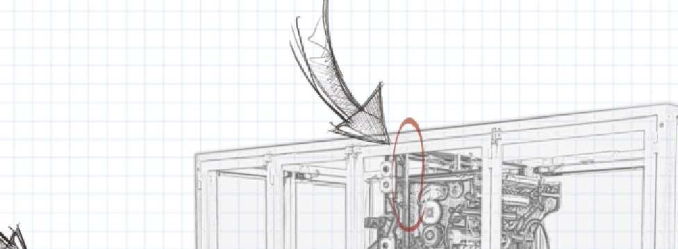
12 2 Introduction 226 VScom USB-16COM Plus There is a special 19-inch mounting kit for two USB-COM Plus models It results in a device with 16 serial ports, connected via the USB-Out port This example uses two USB-8COM Plus (a) 19-Inch mounted complete (b) Left part in Detail (c) Details for Right part Figure 6: VScom USB-16COM Plus 23 Packing List USB-xCOM+ Device CD-ROM containing Drivers Configuration software utility User manual USB 20 High Speed cable 4 rubber feet 3 pin power connector (USB-4COM+ and USB-8COM+ only) 19 Rack mounting brackets (USB-4COM+ and USB-8COM+ only) 12
13 2 Introduction 24 Optional Accessories 241 Mounting Options ArtNo #6692 DK-NCP Din-Rail Kit (USB-COM+ and USB-2COM+ only) ArtNo #6693 WK-NCP Wall-Mount Kit (2 x side wings) ArtNo #6698 DSK-NCP Din-Rail Side Kit (USB-COM+ and USB-2COM+ only) Also order ArtNo #6692 to clip to the Rail ArtNo #6699 DPK-NCP Din-Rail Plastic Kit (2 x DK-35A) Also order ArtNo #6693 to mount on the device USB-COM+ 242 Power Options ArtNo #6031 Power Adaptor 12V@10A (EU plug) (USB-4COM+ and USB-8COM+ only) 25 About this Manual This manual describes the hardware of VScom USB-COM Plus models, as well as signal assignments of the serial connectors The screen shots in here are made on an English language version of Windows 10 It is not difficult to find the appropriate part in any other language version of Windows The current version of the driver is 21214, the version of the firmware in VScom USB-COM+ is 1005 Usually any hardware configuration (see Configuration via DIP Switches) is described before the software, including drivers However the Configuration software utility of VScom USB-4COM Plus and USB-8COM Plus models requires the serial port drivers installed, so these drivers are covered first 13
14 3 The Drivers for Windows 3 The Drivers for Windows This chapter of the manual documents the drivers for Windows Operating Systems The driver is the same for all USB-COM Plus available, independent of the model The USB-COM+ appear in Windows as several components, depending on the specific model This can be seen in the Device Manager, while or after installation of the drivers Single and Dual port models appear as a USB Composite Device first, which installs USB Serial Converter A and B These then install one or two serial ports Multiport models with 4 and 8 serial ports first appear as a Generic USB Hub, plus USB Composite Devices These install USB Serial Converter A to D each The converters then install all the serial ports The models with 4 and 8 serial ports also install an additional virtual serial port, this is later used for configuration by software Windows already provides a driver for a USB Hub, and it also handles USB Composite Devices without configuration and help by the user The specific drivers are required for the USB Serial Adapters, and the USB Serial Ports installed by them The manual first describes the process of installing the driver software, followed by instructions for removing the drivers in the unlikely case you wish to do this After this the configuration of the serial ports is described There is no option to configure the other drivers installed for the USB-COM+, so the options are the same for all different models Many USB-COM+ may be installed simultaneously In fact the driver does not limit the number of USB-COM+ installed, Windows does In Windows the maximum number of serial ports installed is 256, no matter which driver is installed and controls them The current version of the driver for USB-COM+ is With the current driver version there are two methods of installation There is the automatic variant, where Windows detects the new hardware as soon as it is connected to the PC Then Windows contacts to Windows Update and installs the latest version of the drivers The other way of installation operates offline and uses a Pre-Installation Executable to put the drivers onto the system, while the hardware is not yet connected to the PC ce it is connected later, Windows already knows about the drivers, and installs them without further interaction by the user 31 Install Drivers from Windows Update (Automatic) This is the easy method of driver installation for USB-COM Plus models The required steps are very simple First connect your PC to the network, so it can visit the Windows Update websites provided by Microsoft Then connect the USB-COM+ to a USB port of your PC Windows will detect the new hardware, and contact Windows Update for available and latest drivers 14


15 3 The Drivers for Windows (a) Windows XP (b) Vista Figure 7: Confirm Windows Update Vista and Windows XP you have to allow the contact to Windows Update XP select Yes, this time only and proceed, on Vista select Search automatically 15


16 3 The Drivers for Windows (a) Setup Progress (b) Setup on Taskbar (c) In Device Manager Figure 8: Automatic Installation The USB Serial Converters and then the USB Serial Ports are installed with these drivers Depending on the model of USB-COM+ there are several installation tasks operating in parallel If the Device Manager is open at this time the serial ports appear in Other devices first, before installation in Ports (COM&LPT) is finished No interaction from the user is required in this process Note: This is the recommended practice of driver installation However recently the answers from the servers on Windows Update have been seen as rather slow, so this process may take much too long time Then it is better to cancel the installation, and use the driver installation by preinstallation executable If the installed drivers are not the latest version, Windows will update the drivers automatically later 16

17 3 The Drivers for Windows 32 Install Drivers by Pre-Installation Executable (line) The driver installation program is usually named like USBCom-CDM-21214exe, depending on the version number This file is found on the driver CD-ROM Just log on to Windows with Administrator privileges, right-click on the program and select Run as administrator 3 It is a self-extracting archive, which in turn executes the included installation software Just follow the steps shown in figures 9 to 13 Figure 9: Extract to temporary Space 3 Windows XP just double click 17


18 3 The Drivers for Windows Figure 10: Start Installation Figure 11: Confirm License conditions 18


19 3 The Drivers for Windows Figure 12: Copy Files and Install Drivers Figure 13: Installation finished 19
, just say No, not this time to this question In")

20 3 The Drivers for Windows The result of this process4 is a Windows system which has the USB-COM Plus added as known hardware Now connect your USB-COM+ to a USB port on your PC Windows detects the new hardware, and attempts to install the drivers Vista or Windows XP it probably offers the option to search the Internet for more recent drivers (fig 7), just say No, not this time to this question In the next steps select the Automatic option, and click on Next and Finish as requested Windows knows about the drivers, and installs all components and serial ports without further interaction 321 Check Installation of the Drivers Open the Device Manager, and see if all serial ports are available in the Ports Device class Open the properties of each serial port 322 Uninstall Drivers First disconnect all USB-COM Plus from your system the CD-ROM you ll find the CDMuninstallerGUIexe Right-Click on this, and select Run as administrator (a) Uninstaller (b) Removed Figure 14: Uninstall Drivers Change the value in Product ID to the values of 6010, 6011 and 6015 For each value click on the Add button, so the window looks as above Then click on Remove Devices The process shows some removed messages Ignore any messages for failures These may happen when no product with one of the given Product ID is available This is no problem, just continue And finally close the program This procedure not only removes all entries of USB-COM+ from the Device Manager, in the final step also the driver files are removed from the hard disk As a result reconnecting a USB-COM+ causes Windows to start the search for drivers again 4 To have this installation perform really quick, disconnect the PC from any network prior to installation and connection of the USB-COM+ device 20

21 3 The Drivers for Windows 33 Configure the Serial Ports Open the Device Manager In the Device Manager open the device class of Ports (COM & LPT) 5 In this class you ll see all the entries of USB Serial Port Now open the properties of the serial port to configure Figure 15: USB Serial Port Properties Click on the button named Advanced to see the special configuration options They are available via the panel in figure 16 5 Anschlüsse (COM und LPT) in einem deutschen Windows 21

22 3 The Drivers for Windows Figure 16: Advanced port options 331 Rename the Serial Port The option COM Port Number on top of the advanced settings allows to rename the port You may select any free port number It is Windows which refuses a change, if the new port name is already occupied 332 Enable faster Responses The section named BM Options is in the middle of the left part The parameter Latency Timer can be reduced to 1 millisecond, if there are problems with certain applications The default value is 16, to reduce the USB protocol overhead and bandwidth usage Usually the serial port buffers incoming data for up to 16 ms, or until 62 bytes of data are received When either of the criteria becomes true, the data is sent to the Host PC Then the application software will recognize the received data If only a small amount of data is received, or the last part of the transmission does not trigger the 62 byte limit, this causes a short delay in receiving the data As the consequence the application can not operate on the data very early Usually this is not a problem, but with certain serial protocols this can cause strange effects So a reduction to 1 ms is appropriate then, faster reactions are not possible This is caused by the protocol structure of USB, not by the serial port 22
23 3 The Drivers for Windows 333 Miscellaneous Options In the lower right corner of the Advanced Options (figure 16) are some rarely changed options 3331 Serial Enumerator This option is enabled by default When the driver is started, Windows tries to detect hardware attached to the serial port There may be a mouse or a modem Most often the attached device is neither of that, so it is not a problem to disable this option Further some devices permanently send data to the Host, without special requests Windows may falsely recognize such devices as a serial mouse This causes your pointer to randomly jump over the screen Disabling the option prevents this 3332 Serial Printer When flow control like RTS/CTS stops data from being sent to the serial port for a sufficient time, this will cause an error event for the application However if the attached serial device is a printer, sometimes this will halt for paper feed, especially for manual interaction This will cause the data flow to stop for a significant long time Enabling this option causes such errors never to be reported to the application So printing will never cause erroneous error messages 3333 Cancel if Power Instead of a regular shut down the computer can be sent into sleep or hibernate mode In this situation neither the serial port nor the driver can perform any requests In rare situations this can cause problems Enabling this option dumps any open requests for driver or hardware, if the computer is powered off by any Suspend state 3334 Event Surprise Removal Usually this option is disabled because software does not use it When it is enabled, application software can request to be notified if the hardware of the serial port is removed from the system while it is in use So instead of claiming a malfunction of the attached serial device it can correctly report the removal of the port 3335 Set RTS Close Usually the signal RTS is disabled when the port gets closed However some kind of serial hardware may require a permanently active RTS for correct operation Otherwise there may be error messages when the port is opened again to use the device Enabling this option causes the RTS to stay active even when the application closes the serial port 3336 Disable Modem Ctrl At Startup Usually on startup the modem control signals RTS and DTR follow the behavior of standard ports (ie Com1) Due to the longer timing compared to built-in serial ports a very short enable or disable pulse on the control signals may become a comparably long pulse on the USB serial port Such a long pulse can cause external hardware to malfunction By correct configuration of the serial port application software can avoid that problem However since it does not appear on Com1, most software does not care about that This option will help to heal such problem 23
24 3 The Drivers for Windows Note that if the "Serial Enumerator" option is enabled, in the enumeration sequence Windows causes the control signals to change So if it is necessary to select "Disable Modem Ctrl At Startup", it is likely that "Serial Enumerator" should be disabled too 34 USB-COM Plus Configurator To configure all parameters (see section 33) of the serial ports will be a clumsy work To do this in a more easy way there is a special tool to perform this for a collection of ports all at once This is the USB-COM Plus Configurator Figure 17: Driver Configurator In the left list the user selects the COM Ports to configure, multi-select options are available Aside from the indivicual parameters in the top area, there is one button for Default Settings, and a convenient to Optimize for USB-COM This configures for best practice parameters, based on experiences 24
25 4 Hardware Configuration 35 Optimizing Data Throughput Roughly speaking, the USB allows one operation between Host PC and attached USB device per millisecond This is the basic reason why the Latency (see 332) can t be shorter than 1 ms But there is a second effect causing slow transmissions Many software sends the data to the driver byte-by-byte This is not a problem with built-in ports like Com1 Except for extreme high transmission rates the operation time of the driver is much shorter than the serial transmission time So when the second and following byte are sent to the driver, the previous bytes did not completely leave the PC and its buffers The serial port does not run out of data This is different with USB serial ports No matter how fast the byte is transmitted over the USB cable (12 Mbit/s or 480Mbit/s), it takes 1 ms to send the next byte Calculated the other way this is 1000 byte per second, which is equivalent to 9600 bit/s The user feels the transmission as sluggish Raising the serial speed does not help, since this is not the problem However it requires nearly the same millisecond to send one byte or more So if the application sends complete buffers instead byte-by-byte, the driver can send more than one byte per millisecond This way the USB serial port is permanently fed with work to send 4 Hardware Configuration The serial ports of VScom USB-COM Plus are configured by DIP switch The devices with one and two serial ports6 provide a block of switches for each serial port The devices with four and eight serial ports7 provide one common block for all serial ports This either configures all ports to the selected operation mode, or it enables selective per-port configuration by easy to use software There are no Jumpers inside the USB-COM+, so it is never necessary to open the case for configuration The configuration by software of course requires to have a driver for USB Virtual Serial Ports on the system That is not a problem, because without such driver the VScom USB-COM+ can not be used anyway The configuration parameters are saved to a non-volatile memory inside the USB-COM+, so configuration and use may happen on different systems 41 Configuration via DIP Switches 411 Models with e and Two serial Ports The models USB-COM Plus Mini and USB-COM Plus Mini ISO are configured via one block of DIP switches, accessible from the bottom side The models USB-COM Plus, USB-COM Plus ISO, USB-2COM Plus and USB-2COM Plus ISO provide one block of DIP switches for each serial port The switch labeled 4 on each block controls the termination in RS422 and RS485 modes, by attaching 120 Ω to the receiving lines; that switch has no effect in RS232 mode 6 7 USB-COM+ Mini, USB-COM+ Mini ISO, USB-COM+, USB-COM+ ISO, USB-2COM+ and USB-2COM+ ISO USB-4COM+, USB-4COM+ ISO, USB-8COM+ and USB-8COM+ ISO 25
26 4 Hardware Configuration (Bottom) (Top) (a) DIP Switch Description S1 S2 S3 Mode RS232 S4 Termination RS422 Active 120 Ω RS485 4w 1 Inactive 2w 2 (c) Termination for RS422 / RS485 RS485 (b) Operation Mode Table 8: Configuration USB-COM+ Mini (Bottom) (Top) (a) DIP Switch Description S1 S2 S3 Mode RS232 S4 Termination RS422 Active 120 Ω RS485 4w 1 Inactive 2w 2 (c) Termination for RS422 / RS485 RS485 (b) Operation Mode Table 9: Configuration USB-COM+ and USB-2COM+ Note 1: Note 2: This is the Full Duplex Mode This is the Half Duplex Mode Without further specifications this is usually referred to simply as RS485 26
27 4 Hardware Configuration 412 Models with Four and Eight serial Ports The models USB-4COM Plus, USB-4COM Plus ISO, USB-8COM Plus and USB-8COM Plus ISO provide one block of DIP switches, common for all serial ports The configuration selected by this block is either valid for all serial ports on the device Or it is the selection to configure by software, in this case extra software will configure each serial port independent from any other In RS422 and RS485 modes the switch labeled 4 attaches an internal resistor of 120 Ω to the receiving lines In other modes the switch has a different function (Bottom) (Top) (a) DIP Switch Description RS232 RS422 Line Mode, Comment S1 S2 S3 S4 Selected by Software1 Operation 4-wire Operation 4-wire with Rx-Termination 4-wire Operation 4-wire with Rx-Termination 2-wire Operation 2-wire with Termination Switch Positions RS4852 (b) DIP Switch Configurations Table 10: DIP Switches Note 1: Note 2: The Master DIP switches configure all serial ports to a common operation mode If diversity in line operation modes is intended, the switch must be set to»selected by Software«, and the configuration is done via a Windows software or a Terminal Emulation In RS485 mode the USB-COM+ performs the required activation and disabling of the RS485 transmitter by an internal automatic Application software does not have to perform special operations These configurations are selected to be similar with VScom NetCom Plus Serial Device Servers 27
 Then locate the program UsbComCfgexe on your CD-ROM Close any application currently operating via the serial port(s) provided by your USB-COM+ Then start the UsbComCfg")
28 4 Hardware Configuration 42 Configuration via Windows Software This mode of configuration is available on VScom USB-4COM Plus and USB-8COM Plus models If the drivers for Windows are not installed, please do that now (chapter 3) Then locate the program UsbComCfgexe on your CD-ROM Close any application currently operating via the serial port(s) provided by your USB-COM+ Then start the UsbComCfg program, it searches and detects all configurable USB-COM+ Figure 18: No Device UsbComCfg will repeat the search when the appropriate button is clicked 28

29 4 Hardware Configuration Figure 19: e USB-8COM Plus detected The left pane displays all devices detected by the search By clicking a device in the left pane, a port in the middle pane can be selected The operation mode is then changed by the radio buttons and the check box in the right pane The button to Commit Changes transfers the required parameters to the selected device They are stored in non-volatile RAM, and activated after the transfer 29
30 4 Hardware Configuration Figure 20: UsbComCfg Multi-Port Selection You may select several ports of one device at the same time This is done by the usual Windows method, ie clicking with Shift- or Ctrl-Key pressed The selected configuration then applies to all selected ports, Commit Changes configures all of them at the same time Finally in the left pane you may select multiple devices at the same time The configuration then applies to all ports of all selected devices 43 Configuration via Terminal Program Not all systems operate under Windows, and not all users have the UsbComCfg program available when they want to reconfigure the USB-COM Plus Even then the configuration is possible via the virtual serial port implemented by the driver If no driver is available on the system, the USBCOM+ will be of little use anyway If the driver is not installed, please do that now (chapter 3 for Windows) Then open your terminal emulation software, and open the special serial port provided by the USB-COM+ Configure the serial port for bit per second, eight bit per character without parity, and one stop bit (38400,8N1) Flow control is not used Select the terminal emulation as a very dumb terminal Incoming <CR> (Carriage Return characters) shall not result in a line feed, but <BS> (Backspace) should position the cursor one space to the left 30
31 4 Hardware Configuration [8#1005] USB-COM Plus Figure 21: Open Terminal Configuration In your terminal screen press Enter, a line similar to the above will appear The line lists the USB-COM+ found using this serial port, here it notes 8 serial ports and version 1005 ' 0 - Exit Show all port configurations 2 - Change port configurations 3 - Default port configurations 4 - Save port configurations Show configuration file 6 - Upload configuration file > & $ % Figure 22: Terminal Main Menu The Main Menu appears In this and the other menus just type the character given at the beginning of the line, to get the function described there Hit the Enter key to activate the command The optional result as well as the menu will be written on the screen Just test this by hitting 0 and Enter to exit from the configuration In the Main Menu (figure 22) the upper section provides for status information and manual configuration of the serial ports The lower section provides a method to save the configuration, especially for a later upload of these parameters 431 Exit the Configuration (0) > 0 Figure 23: Exit Terminal Configuration Enter a 0 in the Main Menu, this will terminate the Configuration Unsaved changes to the configuration are discarded 432 Show Port Configurations (1) > 1 Port Port Port Port 1: 2: 3: 4: RS232 RS232 RS232 RS232 Figure 24: Show all port configurations 31
32 4 Hardware Configuration The command 1 in the Main Menu lists the current configuration of all serial ports in the USBCOM+ This example is for a USB-4COM Plus with all ports in RS232 mode The list is followed by the Main Menu again 433 Change Port Configuration (2) ' $ > Back Port Port Port Port All Ports > & % Figure 25: Change port configurations Command 2 allows to change the configuration of some ports The ports may be selected individually, or all at once for common configuration 0 Selects the Main Menu again 1 Selects the first serial port 2 Selects the second serial port 3 Selects the third serial port 4 Selects the fourth serial port 5 Selects all serial ports at once This number changes depending on the number of available serial ports For this example port 1 is selected for configuration To get details about the available modes please read section 22 32
33 4 Hardware Configuration ' > 1 ---> Port 1: RS Back RS485 4-wire 2 - RS485 2-wire 3 - RS422 4-wire 4 - RS by Software Termination > & $ % Figure 26: Configure a serial port The options are selected by entering the number, followed by the Enter key 0 Returns to the selection of the serial ports, but so far the configuration is not activated This requires an explicit command, see section Default Port Configuration (3) Option 3 in the Main Menu (figure 22) loads a standard configuration for all ports This is RS232, Termination is disabled 435 Save Port Configurations (4) Each change in Port configuration is temporary, only saved in volatile memory It needs explicit confirmation for using the new configuration Option 4 in the Main Menu (figure 22) performs this operation The configuration data is stored to non-volatile memory inside the USB-COM+, and becomes active 436 Show Configuration File (5) Configuring each serial port (and each option of it) in a USB-COM+ can become a long process And this has to be repeated on the next device, and so on To make the handling much easier the current configuration can be saved to a file, for later use Option 5 in the Main Menu (figure 22) is prepared for this task 33
34 4 Hardware Configuration ' Show configuration file 6 - Upload configuration file > 5 $ file construction (decimal values): port port port <CR> number<cr> mode<cr> (take a look at "Change port configurations") control bits<cr> (bit0: Termination ) (empty line) 99<CR> terminates the file <-- file start --> <-- file end --> & % Figure 27: Saving Configuration file The configuration is displayed on the terminal screen It is preceded by a short description of the file format Using the Terminal Emulation software this output can be captured and saved to a file It depends on the particular software how this is done, so please check your software documentation The configuration of each serial port is written on three distinct lines, followed by an empty line Port number and operation mode are already described Port Control is for Termination: a value of 1 activates this option 437 Upload Configuration File (6) When the Terminal Emulation software allows to save the configuration of the device, it will also allow to send a text file to the USB-COM+ This way a previously saved configuration can be 34
35 5 Technical Background on RS485 loaded to the USB-COM+ It can also be loaded to another device, for ease of configuring a series of USB-COM+ The last option 6 in the Main Menu (figure 22) provides this function 5 Technical Background on RS485 This chapter will provide a little bit of theory about RS422 and RS485 data transmission It is necessary to have this basic knowledge, to avoid or find errors in data transmission Failures in cabling are responsible for the vast majority of transmission problems 51 Transmission Technique RS422 and RS485 use the same balanced transmission method Signals are not transmitted by voltage on a single wire, as RS232 does Instead two wires are used; when one carries high voltage, the other one carries low voltage The signal is defined by the difference in voltage between those two wires This hardens the transmission against noise Usually twisted pairs are used, which further reduces the sensitivity for noise Typical voltages are +4V as high, about +05V as low These voltages are generated and defined against the GND signal of the transmitter The minimum differential voltage is required as ±200mV by the specifications of RS422 and RS485 The receiver detects the polarity of the differential voltage, and thus gets a Zero (negative) or a e (positive) difference To do this detection the voltages on the receivers side have to be inside the bounds of the common voltage range defined as -7V through +12V, as measured against the local GND of the receiver The specification of the common voltage range has been given to make the design of receiver circuits more simple and cost effective To make sure the signals meet the common voltage range, the GND of sender and receiver must be connected somehow, otherwise the voltages are undefined and may have any value To assure the correct range RS485 (RS422) usually requires an extra wire for GND8, which is often forgotten The connection may also happen by protective ground, or by other means If the connection of GND is bad, it may be impossible to receive correct data 52 Termination When transmitted signals arrive at the end of a cable, they get reflected They travel on the cable back and forth some more times, which is called ringing This can cause false reading of transmitted data When the reflections travel on the cable several times, they are damped and do no longer cause errors This happens earlier if the cables are short For long cables Termination Resistors are required These increase the damping of reflections The value of the resistor must match the impedance of the cable, typically 120Ω for twisted pair As a rule of thumb9, when the cables are longer than Bitrate (one million divided by the bit rate) in meters, you should consider Termination Resistors 8 9 with an optional resistor Assuming group speed of km/s, 10 travels to damp out, and 10% of bit time 35
36 5 Technical Background on RS Polarization In RS485 the sender must activate the transmitter before sending data, and deactivate it when all data is sent At times when no devices send data all transmitters are inactive As the result the data lines are floating, and the differential voltage is undefined It may happen the next data is not correctly recognized, because the change from undefined to data signals is not detected To avoid such problems the data lines should be polarized by resistors These insure the differential voltage to be above +200mV Typically the positive line is pulled to +5V, while the negative line is pulled to GND When Termination Resistors are applied, the voltage on these must be +200mV or above When the termination resistors are of the 120Ω types, the polarization resistors shall have about 750 to 1000Ω The Polarization Resistors must not be too small, because they add current to the signals, and a transmitter has to act against that A typical transmitter provides up to 60 ma of current in high and low level 54 2-Wire Scheme In many configurations a very simple cabling is required RS485 allows for so called 2-wire cabling as shown below Several devices are connected in parallel to the wires, which is called bus topology Each device can either send own or receive foreign data at a given time, so it is operating in half-duplex mode Shown in figure 28 are three devices, RS485 specifies up to 32 The data lines are named as Data+ and Data-, a positive differential voltage is the state for a transmitted e The GND is also connected between all devices as required, so the cabling is 3-wire in reality Figure 28: 2-wire cabling scheme The resistors P1 and P2 are for polarization, T1 and T2 are for the termination function Polarization of Data+ and Data- appears only once on this net, the termination is at the physical ends of the cable All devices appear the same on the cable, they have the same function There is no Master or Slave defined by the hardware Such functions are implemented by way of the data transmission protocol Also RS485 addresses are defined by that protocol, as well as bus access 36
37 5 Technical Background on RS Wire Scheme RS422 requires dedicated wire pairs for transmit and receive The transmit wires are used to send data to as many as 10 receivers, as stated in the specifications of RS422 Since the VScom products use RS485 line driver technology, up to 32 receivers are possible While one pair is used to transmit, a second pair is available to receive data at the same time When only two devices are connected, this is a possible replacement of classic RS232 connections (Point-to-Point) In RS485 4-wire mode the transmit wires may be shared between dedicated stations As an example a second station can be a backup master for the network Masters can send data and commands to one station, while they receive information from another device Figure 29: 4-wire cabling scheme Figure 29 displays the wire pairs Tx± and Rx± as named for Devices 1 and 2 There are more slave devices, only two of them are shown The slaves transmit on the Rx-lines, and receive on the Tx-lines To implement the Common Voltage Range as specified the GND line is also connected Masters on the network are identified because they transmit on the Tx-lines The two Masters in figure 29 have to synchronize their use of the Tx-lines be extra means Eg Dev 2 can be a backup master, which is manually activated Also indicated in figure 29 are polarization resistors P1/P2 for Tx± and P3/P4 for Rx±, only once per wire pair Further Termination resistors T1/T2 for Tx± and T3/T4 for Rx± are added, one at each end of the cable To ensure the Common Voltage Range the GND is also connected at each device, making this a 5-wire connection 37
38 6 Connector Definitions 56 USB-COM Plus Devices As described above the USB-COM Plus provide an internal Termination resistor with a value of 120 Ω This is activated by defining the configuration of the serial port The receiver circuits for RS422 and RS485 do not require resistors for BIAS function Using termination resistors the differential voltage is 0 Volt when all devices are inactive The circuits recognize this voltage still as positive, so a logical e is detected Therefore the USB-COM+ do not provide resistors for BIAS function 6 Connector Definitions All the VScom USB-COM Plus devices provide the today standard DSub9 male connector for the signals of the serial ports An adapter to Terminal block for RS422 and RS485 signals is available as an add-on (see 62) The signal assignment for RS232 on DB910 male connectors is defined by the term RS232 already Below is the signal definition for the connectors used by the USB-COM Plus 61 DB9 male Usually this type of connector is used by customers 4w denotes the Full-Duplex mode, usually named 4-wire Similarly 2w denotes the Half-Duplex modes Pin RS232 DCD RxD TxD DTR GND DSR RTS CTS RI RS422 Tx Tx+ Rx+ Rx GND RS485 4w Tx Tx+ Rx+ Rx GND RS485 2w Data Data+ GND Figure 30: DB9 male Connector Table 11: DB9 male Connector 10 Technically correct is DE9 38
39 A History 62 Terminal Block Adapter When using RS422 and RS485 as transmission mode, sometimes the communication cables do not use a connector Instead the wires are directly mounted into a clamp To provide this options an adapter from the DB9 male connector to Terminal Block is available This connects the pins 1 through 5 to a clamp Also pin 9 is connected to an extra clamp, but this is of no use for RS422 and RS485 communication Figure 31: Terminal Block A History October 2015 Release of Products and Manual Update with USB-16COM Plus option and Windows Driver Add USB-COM Plus Configurator Application Add USB-COM Plus Mini device 39


40
User Manual USB-COM ECO
 User Manual USB-COM ECO Edition: February 2017 Tel: +49 40 528 401 0 Fax: +49 40 528 401 99 Web: www.visionsystems.de Support: service@visionsystems.de The software described in this manual is furnished
User Manual USB-COM Plus
 User Manual USB-COM Plus Edition: July 2017 Tel: +49 40 528 401 0 Fax: +49 40 528 401 99 Web: www.visionsystems.de Support: service@visionsystems.de The software described in this manual is furnished under
Serial to RS422/485 Converter SER 485(ISO) User Manual
 User Manual") Serial to RS422/485 Converter SER 485(ISO) User Manual Edition: June 2016 Tel: +49 40 528 401 0 Fax: +49 40 528 401 99 Web: www.visionsystems.de Support: service@visionsystems.de The software described
Serial to RS422/485 Converter SER 485(ISO) User Manual Edition: June 2016 Tel: +49 40 528 401 0 Fax: +49 40 528 401 99 Web: www.visionsystems.de Support: service@visionsystems.de The software described
Serial to RS422/485 Converter SER 485 PRO( SI) User Manual
 User Manual") Serial to RS422/485 Converter SER 485 PRO( SI) User Manual Edition: April 2008 Tel: +49 40 528 401 0 Fax: +49 40 528 401 99 Web: www.visionsystems.de Support: service@visionsystems.de The software described
Serial to RS422/485 Converter SER 485 PRO( SI) User Manual Edition: April 2008 Tel: +49 40 528 401 0 Fax: +49 40 528 401 99 Web: www.visionsystems.de Support: service@visionsystems.de The software described
User Manual VScom PCI Cards VScom Industrial Card
 User Manual VScom PCI Cards VScom Industrial Card Edition: July 2011 Tel: +49 40 528 401 0 Fax: +49 40 528 401 99 Web: www.visionsystems.de Support: service@visionsystems.de The software described in this
USB-COM Plus ISO (USB-COMi SI-M)
") VS Vision Systems GmbH / Part Number 603 Features 1 x RS232/422/485 port USB 2.0 Full Speed interface 2.5kV isolation per serial port USB and serial ports ESD protected Robust metal case Jumperless, DIP
VS Vision Systems GmbH / Part Number 603 Features 1 x RS232/422/485 port USB 2.0 Full Speed interface 2.5kV isolation per serial port USB and serial ports ESD protected Robust metal case Jumperless, DIP
PCI Express 4-Port Industrial Serial I/O Cards
 PCI Express 4-Port Industrial Serial I/O Cards The PCIe-400i and PCIe-400i-SI PCI Express 4-port industrial serial I/O cards are plug & play high-speed serial I/O expansion cards for the PCI Express bus.
Product Manual. USB to Optical Adapter Industrial Isolated RS- 232/422/485. Coolgear, Inc. Version 2.1 December 2018 Model Number: USB-COMi-Si-M
 USB to Optical Adapter Industrial Isolated RS- 232/422/485 Product Manual Coolgear, Inc. Version 2.1 December 2018 Model Number: USB-COMi-Si-M 2 USB-COMi-SI-M Product Manual Revision History Revision Date
OnRISC. OnRISC Baltos ir 2110
 OnRISC OnRISC Baltos ir 2110 Hardware Manual Edition: October 2015 Tel: +49 40 528 401 0 Fax: +49 40 528 401 99 Web: www.visionsystems.de Support: service@visionsystems.de The software described in this
USB-4COM RJ45. Contact Online. More Pictures. Click on the thumbnails for the large picture. Overview
 VS Vision Systems GmbH / Part Number 626 Main Features USB 2.0 to 4 x RS232 ports High-Speed serial ports 460.8kbps Port Expansion via USB 2.0 High Speed Driver for Windows, Linux, Mac OS X LEDs for Power/Ready
USBG-8COM-PRO 8-Port USB to RS-232, 422, 485 Auto Setup Adapter Manual. Features & Specifications. Specifications
 USBG-8COM-PRO 8-Port USB to RS-232, 422, 485 Auto Setup Adapter Manual The USBG-8COM-PRO 2-Port Series Industrial I/O Adapters are advanced USB to Serial Adapters that connect to 1, 2, 4 or 8 RS- 232/422/485
Introduction & Specifications of Hi-Speed USB to Industrial Dual Ports RS-422/485 Adapter
 Introduction & Specifications of Hi-Speed USB to Industrial Dual Ports RS-422/485 Adapter USB to Dual RS-422/485 Adapter (USB-2COMi-M) USB to Dual Opto-isolated RS-422/485 Adapter (USB-2COMi-SI-M) - with
This 4-port RS-422/485 Adapter is provided with an external switching power adapter in the package.
 USB-4COMi-M USB to Quad RS-422/485 to Serial Adapter Manual The USB to Industrial Quad RS-422/485 Adapter is designed to make industrial communication port expansion quick and simple. Connecting to a USB
Installation Guide of Hi-Speed USB to Octal RS-232/422/485 Adapter
 Installation Guide of Hi-Speed USB to Octal RS-232/422/485 Adapter Introduction The USB to Octal Serial Adapter is designed to make serial port expansion quick and simple. Connecting to a USB port on your
Installation Guide of Hi-Speed USB to Industrial Single RS-422/485 Adapter
 Installation Guide of Hi-Speed USB to Industrial Single RS-422/485 Adapter Introduction of USB-COMi and USB-COMi-SI The USB-COMi and USB-COMi-SI Industrial Single RS-422/485 Adapters are designed to make
8 Port USB to RS- 232/422/485 Octal Adapter. Product Manual. Coolgear, Inc. Version 1.1 April 2018 Model Number: USB-8COMi-RM.
 8 Port USB to RS- 232/422/485 Octal Adapter Product Manual Coolgear, Inc. Version 1.1 April 2018 Model Number: USB-8COMi-RM 2 USB-8COMi-RM Product Manual Revision History Revision Date Author Comments
PCIe-400 USER S MANUAL
 PCIe-400 USER S MANUAL 2017 May Edition Titan Electronics Inc. Web: www.titan.tw The computer programs provided with the hardware are supplied under a license. The software provided should be used only
NCOM SERIAL DEVICE SERVER 4XX SERIES USER S MANUAL
 NCOM SERIAL DEVICE SERVER 4XX SERIES USER S MANUAL 2017-07-07 Edition Titan Electronics Inc. Web: www.titan.tw Contents 1. INTRODUCTION... 4 1.1 Key Features... 5 1.2 Specifications... 6 2. PANEL LAYOUT
USB-COMi-TB USB to Industrial Single RS-422 / 485 Adapter Manual. Specifications and Features
 USB-COMi-TB USB to Industrial Single RS-422 / 485 Adapter Manual The USB-COMi-TB USB-to-Industrial Single RS-422/485 Adapter is designed to make industrial communication port expansion quick and simple.
Introduction & Specifications of Hi-Speed USB to Serial Adapters
 Introduction & Specifications of Hi-Speed USB to Serial Adapters The USB Serial Adapters consist of the following models: USB Single Serial Adapter (ES-U-1001, ES-U-1001-A) USB Single Serial Adapter (ES-U-1001-M,
EX KVIS RS232/422/485 3-in-1 Serial to USB Adapter (w/ 4KV Isolation, 15KV ESD Surge Protection)
") EX-1331-4KVIS RS232/422/485 3-in-1 Serial to USB Adapter (w/ 4KV Isolation, 15KV ESD Surge Protection) 1. Introduction Thank you for purchasing this RS232/422/485 3-in-1 Serial to USB Adapter. It is an
EX-1331-4KVIS RS232/422/485 3-in-1 Serial to USB Adapter (w/ 4KV Isolation, 15KV ESD Surge Protection) 1. Introduction Thank you for purchasing this RS232/422/485 3-in-1 Serial to USB Adapter. It is an
Product Manual. 2 Port USB to RS-422 /485 Optical Isolated Adapter. Coolgear, Inc. Version 1.1 March 2018 Model Number: USB-2COMi-Si-M
 2 Port USB to RS-422 /485 Optical Isolated Adapter Product Manual Coolgear, Inc. Version 1.1 March 2018 Model Number: USB-2COMi-Si-M 2 USB-2COMi-Si-M Product Manual Revision History Revision Date Author
EasySYNC Ltd. USB to Serial Converters Manual
 EasySYNC Ltd Document Reference No.: ES_000061 Issue Date: 2011-08-23 The ES-U-xxxx-x adapters are a series of USB Serial Converters from EasySYNC Ltd. They provide a simple method of adapting legacy RS-232
Product Manual. Single Port RS-232 USB Serial Adapter Optical- ISO Surge Protection. Coolgear, Inc. Version 1.1 March 2018 Model Number: USB-COM-Si-M
 Single Port RS-232 USB Serial Adapter Optical- ISO Surge Protection Product Manual Coolgear, Inc. Version 1.1 March 2018 Model Number: USB-COM-Si-M 2 USB-COM-Si-M Product Manual Revision History Revision
USB-16COMi-M 16-Port RS-422/485 USB Serial Adapter User Manual. Features and Specifications. Power Supply
 USB-16COMi-M 16-Port RS-422/485 USB Serial Adapter User Manual The USB to industrial 16-Port RS-422/485 Adapter is designed to make serial port expansion quick and simple. Connecting to a USB port on your
USB to RS-232/RS422/485. US-101-I USB To Serial Operation Manual
 USB to RS-232/RS422/485 US-101-I USB To Serial Operation Manual First Edition, Jun 2008 Table of Contents 1. Introduction 2 2. Package checklist 3 3. Product Specification 4 4. Product Panel Views Description
Installation Guide of Hi-Speed USB to Industrial I/O Adapter
 Installation Guide of Hi-Speed USB to Industrial I/O Adapter Introduction of USB-COMi-SI-M The USB Industrial I/O Adapter is designed to make industrial communication port expansion quick and simple. Connecting
NCOM SERIAL DEVICE SERVER 1XX SERIES USER S MANUAL
 NCOM SERIAL DEVICE SERVER 1XX SERIES USER S MANUAL 2017-07-07 Edition Titan Electronics Inc. Web: www.titan.tw Contents 1. INTRODUCTION... 4 1.1 Key Features... 5 1.2 Specifications... 6 2. PANEL LAYOUT
EasySYNC Ltd. USB to Serial Converters Manual
 EasySYNC Ltd Document Reference No.: ES_000061 Issue Date: 2011-01-26 The ES-U-xxxx-x adapters are a series of USB Serial Converters from EasySYNC Ltd. They provide a simple method of adapting legacy RS-232
USB SERIAL OVER IP ADAPTER AnyplaceUSB-xCOM USER S MANUAL
 USB SERIAL OVER IP ADAPTER AnyplaceUSB-xCOM USER S MANUAL 2018 August Edition Titan Electronics Inc. Sharing Serial Ports over Ethernet and the Internet www.titan.tw The computer programs provided with
NetCom Plus 113 (NetCom 113, NetCom 113 PRO)
") VS Vision Systems GmbH / Part Number 6645 Main Features Ethernet to serial 1 port RS232/422/485 Virtual Com Port driver for Windows Secure Server with latest SSL/AES-256 encryption Operation in Driver
VS Vision Systems GmbH / Part Number 6645 Main Features Ethernet to serial 1 port RS232/422/485 Virtual Com Port driver for Windows Secure Server with latest SSL/AES-256 encryption Operation in Driver
PCI Express 16-Port Serial I/O Cards
 PCI Express 16-Port Serial I/O Cards The PCIe-1600 PCI Express 16-port serial I/O card is a plug & play high-speed serial I/O expansion card for PCI Express bus. Connecting to a PCI Express bus on your
Installation Guide of Hi-Speed USB-to-Optically Isolated RS-422/485 Adapter
 Installation Guide of Hi-Speed USB-to-Optically Isolated RS-422/485 Adapter Introduction of ES-U-2101-M The USB-to-Optically Isolated RS-422/485 Adapter is designed to make industrial communication port
NetCom Plus 113. Contact Online. More Pictures. Click on the thumbnails for the large picture. Overview
 VS Vision Systems GmbH / Part Number 6645 Features Controls 1 RS232/422/485 device located virtually anywhere via Ethernet, WLAN or Internet Easy selection of RS232, RS422 or RS485 by single DIP switch
I-7560U/7561U/7563U. User Manual WARRANTY WARNING COPYRIGHT TRADEMARKS CONTACT US
 I-7560U/7561U/7563U User Manual USB tto RS--232//422//485 Converrtterrss Verr.. 1..0,, Decc.. 2013 WARRANTY All products manufactured by ICP DAS are warranted against defective materials for a period of
USB-2COM-BB USER S MANUAL
 USB-2COM-BB USER S MANUAL 2017 May Edition Titan Electronics Inc. Web: www.titan.tw The computer programs provided with the hardware are supplied under a license. The software provided should be used only
Moxa TCC-100 Series Hardware Installation Guide
 Moxa TCC-100 Series Hardware Installation Guide Twelfth Edition, January 2015 www.moxa.com/product 2015 Moxa Inc. All rights reserved. P/N: 1802001000319 Moxa TCC-100 Series Hardware Installation Guide
MEC-COM-M154. User s Manual
 MEC-COM-M154 Mini PCI-e 2-port RS-232 and 2-port RS232/422/485 serial board with power input User s Manual Third Edition, February 2014 2014 Cervoz Co., Ltd. All rights reserved. Reproduction without permission
Moxa TCC-100 Series User s Guide
 Moxa TCC-100 Series User s Guide Eighth Edition, February 2009 www.moxa.com/product 2009 Moxa Inc. All rights reserved. Reproduction without permission is prohibited. Moxa TCC-100 Series User s Guide The
User s Manual Printed Sep Rev 1.2
 TRP-C08M USB To 4 RS232/422/485 Isolated Converter User s Manual Printed Sep. 2014 Rev 1.2 Trycom Technology Co.,Ltd No.35, Zhongxing Rd., Guishan Township, Taoyuan County 333, Taiwan. Tel : 886-3-350-3351
USB to RS-232/RS422/485. URK-228-I USB To Serial Operation Manual
 USB to RS-232/RS422/485 URK-228-I USB To Serial Operation Manual First Edition, Feb 2012 Table of Contents 1. Introduction 2 2. Package checklist 3 3. Product Specification 4 4. Product Panel Views Description
TRP-C08M. USB To 4 RS232/422/485 Isolated Converter. User s Manual. Printed Jun Rev 1.0
 TRP-C08M USB To 4 RS232/422/485 Isolated Converter User s Manual Printed Jun. 2013 Rev 1.0 Trycom Technology Co., Ltd 1F, No.2-11, Sihu street, Yingge Township, Taipei, Taiwan ROC Tel: 886-2-86781191,
UPort 2000 Series User s Manual
 User s Manual Second Edition, December 2012 www.moxa.com/product 2012 Moxa Inc. All rights reserved. User s Manual The software described in this manual is furnished under a license agreement and may be
Manual Industry Interfaces
 Manual Industry Interfaces W&T Release. Type 0, 0 0, 00 0, 0 0, 0 Industry Interfaces 0/0 by Wiesemann & Theis GmbH Subject to errors and changes: Since we can make mistakes, none of our statements should
Industrial Isolated Converters
 ICD120A ICD140A Product Data Sheet Industrial Isolated Converters ICD120A Features Suitable for use in Class 1, Division 2, Groups A, B, C, and D Hazardous Locations, or Nonhazardous locations only. Easy
USB to RS-422/485 Serial Adapter
 USB to RS-422/485 Serial Adapter User Manual Ver. 4.00 All brand names and trademarks are properties of their respective owners. Contents: Chapter 1: Introduction... 3 1.1 Product Introduction... 3 1.2
8S RS232/422/485 Combo to USB2.0 Module Box Installation Guide
 Installation Guide Congratulation on your purchasing this high performance 8-port RS232/422/485 Combo to USB2.0 Module Box. The product includes a metal module box and a USB cable. Each box has an upstream
Korenix JetCard Series Multiport Serial Card/Ethernet Switch Card User s Manual
 Korenix JetCard Series Multiport Serial Card/Ethernet Switch Card User s Manual Third Edition, Dec. 2008 www.korenix.com Korenix JetCard Series Multiport Serial Card/Ethernet Switch Card User s Manual
TRP-C08S. USB to 1 RS232 and 1 RS422/485 Isolated Converter. User s Manual
 TRP-C08S USB to 1 RS232 and 1 RS422/485 Isolated Converter User s Manual Printed Sep. 2014 Rev 1.4 Trycom Technology Co.,Ltd No.35, Zhongxing Rd., Guishan Township, Taoyuan County 333, Taiwan. Tel : 886-3-350-3351
TRP-C08X. USB To 4 RS232/422/485 Converter. User s Manual
 TRP-C08X USB To 4 RS232/422/485 Converter User s Manual Printed Sep. 2014 Rev 1.2 Trycom Technology Co.,Ltd No.35, Zhongxing Rd., Guishan Township, Taoyuan County 333, Taiwan. Tel : 886-3-350-3351 Fax:
VirtualSCADA VSU-485G USB to RS422/485 Isolated Converter User Manual
 VirtualSCADA USB to RS422/485 Isolated Converter User Manual Revision 1.01.00 Page 1 (15) Table of contents Warranty and support... 3 Product return... 3 1 About the VirtualSCADA USB to RS422/485 Converter...
NetCom Plus 111 (NetCom 111)
") VS Vision Systems GmbH / Part Number 6640 Main Features Ethernet to serial 1 port RS232 Virtual Com Port driver for Windows Secure Server with latest SSL/AES-256 encryption Operation in Driver Mode, TCP/IP
VS Vision Systems GmbH / Part Number 6640 Main Features Ethernet to serial 1 port RS232 Virtual Com Port driver for Windows Secure Server with latest SSL/AES-256 encryption Operation in Driver Mode, TCP/IP
MEC-COM-M134. User s Manual
 MEC-COM-M134 Mini PCI-e 4-port RS-232/422/485 serial board with power input User s Manual Third Edition, February 2014 Mini PCI-e Serial Card User s Manual 2 Table of Contents Chapter 1 Introduction 4
OnRISC Alekto 2 Hardware Manual
 OnRISC Alekto 2 Hardware Manual Edition: September 2013 Tel: +49 40 528 401 0 Fax: +49 40 528 401 99 Web: www.visionsystems.de Support: service@visionsystems.de The software described in this manual is
TRP-C08S. USB To 1* RS232 and 1*RS422/485 Isolated Converter. User s Manual. Printed Jun Rev 1.2
 TRP-C08S USB To 1* RS232 and 1*RS422/485 Isolated Converter User s Manual Printed Jun. 2007 Rev 1.2 Trycom Technology Co., Ltd 1F, No.2-11, Sihu street, Yingge Township, Taipei, Taiwan ROC Tel: 886-2-86781191,
MEC-COM-M114. User s Manual
 MEC-COM-M114 Mini PCI-e 4-port RS-232 serial board with power input User s Manual Third Edition, February 2014 2014 Cervoz Co., Ltd. All rights reserved. Reproduction without permission is prohibited Mini
NetCom Plus 413 POE. Contact Online. More Pictures. Click on the thumbnails for the large picture. Overview
 VS Vision Systems GmbH / Part Number 6676 NetCom Plus 413 POE Features Controls 4 RS232 or RS422/485 devices located virtually anywhere via Ethernet, WLAN or Internet Easy selection of RS232, RS422 or
NetCom Mini. SCADA system Building automation system Self-service banking system Other remote and distributed serial devices control
 Features Can control 1 x RS232 device located virtually anywhere (via Ethernet or Internet) LAN interface 10BaseT/100BaseTx Ethernet Configuration utility automatically finds NetCom Mini devices in the
3.1 I-7560 Pin Assignment and Specifications: Introduction
 3.1 I-7560 Pin Assignment and Specifications: Introduction The I-7560 adds a Windows serial Com port via its USB connection and is compatible with new & legacy RS-232 devices. USB Plug and Play allows
Product Manual. 8-Port RS-232 USB to Serial Adapter Data Control Box. Coolgear, Inc. Version 1.1 September 2017 Model Number: USB-8COM
 8-Port RS-232 USB to Serial Adapter Data Control Box Product Manual Coolgear, Inc. Version 1.1 September 2017 Model Number: USB-8COM 2 USB-8COM Product Manual Revision History Revision Date Author Comments
EX & EX-45362IS 2S RS232/422/485 3-in-1 Serial PCIe Card
 EX-45362 & EX-45362IS 2S RS232/422/485 3-in-1 Serial PCIe Card Congratulation on your purchasing this high performance 2-Port RS232/422/485 3-in-1 Serial PCIe Host Adapter. The adapter is high speed PCIe
USB Connectivity. USB Connectivity
 Connectivity Product Selection Guides -to-serial Server Selection Guide.......................................-2 Hub Selection Guide................................................-4 -to-serial Converters
JetCon 1100 / User s Manual. USB to Serial Converter series. Version 1.0
 JetCon 1100 / 1200 USB to Serial Converter series User s Manual Version 1.0 www.korenix.com 1 JetCon 1100 / JetCon 1200 User s Manual Copyright Notice Copyright 2013 Korenix Technology Co., Ltd. All rights
USB to DB25 RS232 Adapter User Manual. Features. Windows 7/ Vista / 2003 / XP / 2000 Driver Installation
 765289 USB to DB25 RS232 Adapter User Manual The USB Serial Adapter is designed to make serial port expansion quick and simple. Connecting to a USB port on your computer or USB hub, the USB Serial Adapter
USB to RS232 Converter USB-013 (Rev3) User s Manual Ver. 1.2 HuMANDATA LTD.
 User s Manual Ver. 1.2 HuMANDATA LTD.") USB to RS232 Converter USB-013 (Rev3) User s Manual Ver. 1.2 HuMANDATA LTD. Table of Contents Precautions... 1 Revision History... 2 Introduction... 2 1. Overview... 3 2. Power Supply... 3 3. Specifications...
USB to RS232 Converter USB-013 (Rev3) User s Manual Ver. 1.2 HuMANDATA LTD. Table of Contents Precautions... 1 Revision History... 2 Introduction... 2 1. Overview... 3 2. Power Supply... 3 3. Specifications...
MGate TM EIP3000 DF1 to EtherNet/IP Gateway User s Manual
 MGate TM EIP3000 DF1 to EtherNet/IP Gateway User s Manual First Edition, June 2009 www.moxa.com/product 2009 Moxa Inc. All rights reserved. Reproduction without permission is prohibited. MGate EIP3000
NetCom 413 PRO. Contact Online. More Pictures. Klick on the thumbnails for the large picture. Overview
 VS Vision Systems GmbH / Part Number 676 Features Controls 4 RS232/422/485 devices located virtually anywhere via Ethernet or Internet Secure encryption on Ethernet LAN interface 10BaseT/100BaseTx Ethernet
Bluetooth to RS-232&RS422/485. EX-9132B/BI Bluetooth Adapter Operation Manual
 Bluetooth to RS-232&RS422/485 EX-9132B/BI Bluetooth Adapter Operation Manual First Edition, Jun 2008 Table of Contents 1. Introduction 2 2. Package checklist 3 3. Product Specification 4 4. Product Panel
NetCom Plus 413 (NetCom 413, NetCom 413 PRO)
") VS Vision Systems GmbH / Part Number 6675 Main Features Ethernet to serial 4 port RS232/422/485 Virtual Com Port driver for Windows Secure Server with latest SSL/AES-256 encryption Operation in Driver
VS Vision Systems GmbH / Part Number 6675 Main Features Ethernet to serial 4 port RS232/422/485 Virtual Com Port driver for Windows Secure Server with latest SSL/AES-256 encryption Operation in Driver
USB RS485 High Isolated Industry Converter Box for DIN Rail - product #248
 Our Products: USB High Speed - High Isolated - Industry Converter Interfaces Highest quality - on the basis of our experience - we not accept compromise! USB 2.0 - RS485 High Isolated Industry Converter
Product Manual. USB BAY-4 Port Serial DB- 9 RS-232 Adapter with FTDI Chipset. Coolgear, Inc. Version 1.1 September 2017 Model Number: USBG-BAY4
 USB BAY-4 Port Serial DB- 9 RS-232 Adapter with FTDI Chipset Product Manual Coolgear, Inc. Version 1.1 September 2017 Model Number: USBG-BAY4 2 USBG-BAY4 Product Manual Revision History Revision Date Author
OnRISC Baltos Hardware Manual
 OnRISC Baltos Hardware Manual Edition: September 2015 Tel: +49 40 528 401 0 Fax: +49 40 528 401 99 Web: www.visionsystems.de Support: service@visionsystems.de The software described in this manual is furnished
NetCom Plus 211. Contact Online. More Pictures. Click on the thumbnails for the large picture. Overview
 VS Vision Systems GmbH / Part Number 6650 Features Controls 2 RS232 devices located virtually anywhere via Ethernet, WLAN or Internet Port expansion over USB A connector LAN 1000/100/10 Ethernet auto-detect
MGate MB3000 Modbus Gateway User Manual
 MGate MB3000 Modbus Gateway User Manual Sixth Edition, July 2012 www.moxa.com/product 2012 Moxa Inc. All rights reserved. MGate MB3000 Modbus Gateway User s Manual The software described in this manual
Product Manual. USB 2.0 to Serial High- Speed RS-232 Industrial Adapter. Coolgear, Inc. Version 1.1 September 2017 Model Number: USB-COM-M
 USB 2.0 to Serial High- Speed RS-232 Industrial Adapter Product Manual Coolgear, Inc. Version 1.1 September 2017 Model Number: USB-COM-M 2 USB-COM-M Product Manual Revision History Revision Date Author
UPort 1100 Series User s Manual
 Fourth Edition, April 2009 www.moxa.com/product 2009 Moxa Inc. All rights reserved. Reproduction without permission is prohibited. The software described in this manual is furnished under a license agreement
User Manual. NetCom Lite. Edition: January 2012
 User Manual NetCom Lite Edition: January 2012 Tel: +49 40 528 401 0 Fax: +49 40 528 401 99 Web: www.visionsystems.de Support: service@visionsystems.de The software described in this manual is furnished
MEV Limited USB232/485 INSTRUCTION MANUAL
 MEV Limited USB232/485 INSTRUCTION MANUAL USB TO RS232 / RS485 SERIAL COMMUNICATIONS INTERFACE WITH ISOLATION OPTION Issue 5 LIST OF CONTENTS 1 INTRODUCTION 1 1.1 The Products Described in this Manual
USB Port USB Serial DB-9 RS-232 Adapter FTDI Chipset. Product Manual. Coolgear Version 1.0 January 2018 Model Number: USB2-4COM-M
 USB 2.0 4-Port USB Serial DB-9 RS-232 Adapter FTDI Chipset Product Manual Coolgear Version 1.0 January 2018 Model Number: USB2-4COM-M 2 USB2-4COM-M PRODUCT MANUAL Revision History Revision Date Author
User Manual Man NetCom Plus Edition: April 2017
 User Manual NetCom Plus Edition: April 2017 Tel: +49 40 528 401 0 Fax: +49 40 528 401 99 Web: www.visionsystems.de Support: service@visionsystems.de The software described in this manual is furnished under
MGate MB3000 Modbus Gateway User s Manual
 User s Manual Seventh Edition, May 2013 www.moxa.com/product 2013 Moxa Inc. All rights reserved. User s Manual The software described in this manual is furnished under a license agreement and may be used
UPort 1200/1400/1600 Series User s Manual
 UPort 1200/1400/1600 Series User s Manual Fourth Edition, June 2008 www.moxa.com/product 2008 Moxa Inc., all rights reserved. Reproduction without permission is prohibited. UPort 1200/1400/1600 Series
MODEL USB-FLEXCOM4. USB to Four RS-232/422/485 Serial Ports and MODEL USB-COM232-4A USB to Four RS-232 Serial Ports USER MANUAL
 Embedded Solutions MODEL USB-FLEXCOM4 USB to Four RS-232/422/485 Serial Ports and MODEL USB-COM232-4A USB to Four RS-232 Serial Ports USER MANUAL FILE: MUSB-FLEXCOM4.B1f ADL Embedded Solutions GmbH, Eiserfelder
SER-4485-SI-M USER S MANUAL
 SER-4485-SI-M USER S MANUAL 2017 May Edition Titan Electronics Inc. Web: www.titan.tw The computer programs provided with the hardware are supplied under a license. The software provided should be used
RS-422/485 PCIe Card
 RS-422/485 PCIe Card User Manual Ver. 3.00 All brand names and trademarks are properties of their respective owners. Contents: Chapter 1: Introduction... 3 1.1 Product Introduction... 3 1.2 Features...
MultiPort USB User Manual
 MultiPort USB User Manual Version 2.8 2011. 07. 16 Revision History Revision Date Version Pages Description 2006-07-14 2.0 All Initial Release by shlee 2007-08-02 2.1 Partial Vista x32 added khheo 2008-05-13
RS-422/485 PCI Card User Manual Ver All brand names and trademarks are properties of their respective owners.
 RS-422/485 PCI Card User Manual Ver. 2.00 All brand names and trademarks are properties of their respective owners. Contents: Chapter 1: Introduction... 3 1.1 Product Introduction... 3 1.2 Features...
ELAN DIGITAL SYSTEMS LTD. CF428 COMPACT FLASH CF+ CARD USER S GUIDE
 ELAN DIGITAL SYSTEMS LTD. LITTLE PARK FARM ROAD, SEGENSWORTH WEST, FAREHAM, HANTS. PO15 5SJ. TEL: (44) (0)1489 579799 FAX: (44) (0)1489 577516 e-mail: support@pccard.co.uk website: http://www.pccard.co.uk
Ethernet Serial Server
 Ethernet Serial Server Users Manual Eport-101, Eport-102, Eport-104, Eport108 1 INTRODUCTION... 1 1.1 FEATURES... 1 1.2 PRODUCT SPECIFICATIONS... 2 1.3 DEFAULT SETTINGS... 3 2 COMMUNICATION MODES... 4
MAP/950 SERIAL I/O CARD INSTALLATION MANUAL
 MAP/950 4 PORT ISOLATED RS422/RS485 PCI SERIAL I/O CARD INSTALLATION MANUAL HIGH-PERFORMANCE UART FAMILY This document describes the installation and use of the Axxon Computer Corporation MAP/950 4 Port
USB to Single RS-422/485 Adapter - with optical isolation and surge protection (USB-COMi-SI)
") USB Installation Industrial Guide I/O Adapter of Hi-Speed The USB Industrial I/O Adapters consist of the following models: USB to Single RS-422/485 Adapter (USB-COMi) USB to Single RS-422/485 Adapter -
USB Installation Industrial Guide I/O Adapter of Hi-Speed The USB Industrial I/O Adapters consist of the following models: USB to Single RS-422/485 Adapter (USB-COMi) USB to Single RS-422/485 Adapter -
PCIe Card Selection Guide. PCIe-CAN Card. PCIe-COM Card. Taiwan Pulse Motion Co.,Ltd. Bus Interface PCI Express x 1 LPE-C122 PCE-C122D PCE-C122T
 PCIe Card Selection Guide PCIe-CAN Card Bus Interface PCI Express x 1 LPE-C122 PCE-C122D PCE-C122T Channels I/O Isolation Voltage Baud Rate Terminator Resistor I/O PIN Type 2 Max. 1 Mbps Jumper for 120
Mini USB to RS-232 Serial Adapter DB-9 Male Converter. Product Manual. Coolgear Version 1.0 January 2018 Model Number: USBG-232MINI.
 Mini USB to RS-232 Serial Adapter DB-9 Male Converter Product Manual Coolgear Version 1.0 January 2018 Model Number: USBG-232MINI 2 USBG-232MINI PRODUCT MANUAL Revision History Revision Date Author Comments
User Manual A08. User Manual
 A08 TABLE OF CONTENTS TABLE OF CONTENTS... 1 1. INTRODUCTION... 2 1.1. Key Features... 3 1.2. OS Requirement... 4 1.3. Specification... 4 1.4. Packing List... 4 2. OVERVIEW... 5 2.1. LED Definition...
Media Converters. Media Converters. Product Selection Guides
 Product Selection Guides Media Converters Serial-to-Fiber Converter Selection Guide....................................-2 Serial-to-Serial Converter Selection Guide...................................-3
NPort S8000 Series Quick Installation Guide
 NPort S8000 Series Quick Installation Guide Edition 6.0, March 2016 Technical Support Contact Information www.moxa.com/support Moxa Americas: Toll-free: 1-888-669-2872 Tel: 1-714-528-6777 Fax: 1-714-528-6778
Hardware Manual RM CANview
 Hardware Manual RM CANview 1998-2005 RM Michaelides Software & Elektronik GmbH Donaustraße 14 D-36043 Fulda Germany cv_hw_e.doc Table of Contents 1 Legal Regulations...3 2 About the CANview...4 3 Important
ELAN DIGITAL SYSTEMS LTD. SL332 PC- CARD USER S GUIDE
 ELAN DIGITAL SYSTEMS LTD. LITTLE PARK FARM ROAD, SEGENSWORTH WEST, FAREHAM, HANTS. PO15 5SJ. TEL: (44) (0)1489 579799 FAX: (44) (0)1489 577516 e-mail: support@pccard.co.uk website: http://www.pccard.co.uk
MODEL USB-COM-2SM USER MANUAL
 C (C C MODEL USB-COM-2SM USER MANUAL FILE: MUSB-COM-2SM.A1a Notice The information in this document is provided for reference only. Portwell does not assume any liability arising out of the application
Arm-based DIN-rail industrial computers with 4 serial ports, 2 LAN ports, 8 DI/DO, and VGA. Features and Benefits. Certifications
 IA260 Series Arm-based DIN-rail industrial computers with 4 serial ports, 2 LAN ports, 8 DI/DO, and VGA Features and Benefits Cirrus Logic EP9315 Arm9 CPU, 200 MHz 128 MB RAM onboard, 32 MB flash disk