DALI Professional Frequently asked questions Light is OSRAM
|
|
|
- Eleanore Spencer
- 5 years ago
- Views:
Transcription


1 DALI Professional Frequently asked questions Light is OSRAM
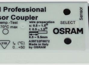
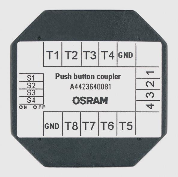
2 DALI PROFESSIONAL Frequently Asked Questions What is the max. cable length in OSRAM DALI PROFESSIONAL system? Is it 300 m in total for all 4 DALI lines or 300 m per each DALI line? DALI lines are released for 300 m with 1.5 mm 2 standard copper installation wires. The DALI PROFESSIONAL controller CONT-4 provides 4 electrical independent DALI lines which can be wired in opposite directions with the CONT-4 in the center. What is the wiring concept for DALI projects? DALI line topology is linear or star up to 300 m max. distance at min. 1.5 mm 2 copper wire. But no closed loops, no ring topology. Do not mix with TOUCH DIM applications. Avoid shortcuts. DALI wiring needs only basic insulation to mains voltage, so standard installation cable NYM 5x1,5 mm 2 is recommended. How many DALI ECGs can be used? In DALI there are 64 DALI ECG addresses per DALI line which results in 128 ma DALI current consumed by these ECGs. Because we have 4 DALI lines in DP CONT-4, there can be used max. 256 ECGs. For ECG with more addresses per unit (e.g. OSRAM OTi DALI 75 with optional 4 addresses) the max. number is reduced accordingly. How many DALI ECGs can be controlled individually in OSRAM DALI PROFESSIONAL? DALI PROFESSIONAL provides in total 256 DALI ECG addresses divided into 4 DALI lines. To control these individually you need 256 buttons or 64 pushbutton couplers which exceeds the maximum DALI current. With this you can only control 220 ECGs individually. To achieve a full individual control of all 256 ECGs, we recommend to use 22 Glasstouches (12 buttons each) combined with the according e:bus gateways / power supplies. How many DALI input devices can be used? In our system there are 64 DALI Input Devices addresses per DALI line. Because there are 4 DALI lines in DALI PROFESSIONAL Controller CONT-4 max. 800 ma DALI current can be used in total including the ECGs. This leaves approx. 280 ma for Input Devices if all 256 ECGs are installed. The remaining DALI current to be consumed by input devices depends on mix of types (OSRAM DALI Pushbutton Coupler 6 ma, OSRAM DALI Sensorcoupler 5 ma). For input devices with more addresses per unit (e.g. OSRAM DALI Sensorcoupler with 2 addresses), the maximum devices number by addresses is reduced accordingly. How many pushbuttons can be used in OSRAM DALI PROFESSIONAL? Final number is depending on mix of products in the configuration. Theoretical there are 64 input device addresses per DALI line. But in most applications the limiting factor is the current : each DALI line of CONT-4 provides 200 ma DALI current which has to be shared between ECGs and input devices. So if all 64 ECGs are installed you can add 12 OSRAM DALI Pushbutton Couplers (48 buttons) or 7 OSRAM DALI Pushbutton Couplers (28 buttons) and 5 OSRAM DALI Sensorcouplers (5 light sensors + 5 occupancy sensors). How many sensors can be used in OSRAM DALI PROFESSIONAL? Final number is depending on mix of products in the configuration. Theoretical there are 64 input device addresses per DALI line. But in most applications the limiting factor is the current : each DALI line of CONT-4 provides 200 ma DALI current which has to be shared between ECGs and input devices. So if all 64 ECGs are installed you can add 14 OSRAM DALI Sensorcouplers (14 lightsensors + 14 occupancy sensors) or 7 OSRAM DALI Pushbutton Couplers (28 buttons) + 5 OSRAM DALI Sensorcouplers (5 lightsensors + 5 occupancy sensors). What is the maximum pushbutton distance to OSRAM DALI Pushbutton Coupler? We allow a maximum wiring length of 2 m from pushbutton to OSRAM DALI Pushbutton Coupler. We recommend to install the pushbutton coupler behind the pushbutton in an installation box using the wires delivered with the device. What is the maximum sensor distance to OSRAM DALI Sensorcoupler? A maximum wiring length of 5 m from Sensor to OSRAM DALI Sensorcoupler is allowed. Recommended is OSRAM MULTI3 wiring material like Y-Connector. ZPE EN Page 2 of 11

3 How many DALI groups can be configured? In DALI an ECG is able to store up to 16 group affiliations. OSRAM DALI PROFESSIONAL Controller CONT-4 provides 4 DALI lines, so there are maximum 64 DALI groups. In case of group overlap from one DALI line to another the same group is used two times. With this the maximum number is reduced by one. If the maximum number of groups is used up the controller creates automatically additional virtual groups by sending serial addressed commands. But the reaction time / synchronisation can be effected. How many DALI scenes can be configured? In DALI an ECG is able to store up to 16 scene values. OSRAM DALI PROFESSIONAL Controller CONT-4 provides 4 DALI lines, so there are maximum 64 scenes. In case of scene overlap from one DALI line to another the same scene is used two times and the maximum number is reduced by one. If more than 16 scenes per DALI line are used there will be an error message. Using additional virtual scenes with DALI would lead to unacceptable delays and asynchronous behaviour. We recommend for complex animations to use OSRAM EASY system where the sequences are stored in the ECG. Even bigger installations can be made with DMX systems from traxon / e:cue. For what reason we recommend to use 230V buttons / switches for OSRAM DALI Pushbutton Coupler input contacts? There is no technical reason for that, also a 12 V bell button would work, but there are regulations. DALI wiring needs only basic insulation, therefore it has to be handled like mains voltage. The wallbox geometry of the pushbutton coupler does not allow to design the necessary safety distances. For this reason also the connected buttons have to be handled like mains voltage devices. Is there a possibility to control the lights by PC? The PC connection in OSRAM DALI PROFESSIONAL system is only designed for setup process and configuration, not for permanent use in the application. But via a PC output (e.g. I/O card with dry contact relay) input events can be generated to the pushbutton coupler which can start actions in the DALI system. How can I backload a project from the controller? Connect controller by USB with PC, click to the connection symbol. Click to download from controller symbol to retrieve existing configuration from controller. Works only if project is uploaded before with Software DALIpro v Can I check the device status during system operation? There is no visualisation of single device status after the setup is finshed and the controller is disconnected from PC. But the LEDs on controller front show lamp errors and DALI shortcuts per DALI line. The DALI PROFESSIONAL PC screen / GUI is only designed as a tool for setup, not for monitoring a running application. If this functionality is requested another system type has to be used. In building management systems based on KNX, LON, BacNet this feature is usually existing and the status is possible to be shown online on a central screen. How can I integrate a remote control into OSRAM DALI PROFESSIONAL system? Use the OSRAM TOUCH DIM RC device as receiver and connect the output contacts to a OSRAM DALI Pushbutton Coupler. The RF signal can be generated from any Enocean button signal source. One OSRAM TOUCH DIM RC can handle two Enocean channels. ZPE EN Page 3 of 11

 Electrical Solution 230V AC B) Software Solution in DALIpro GUI Put all switches into one function and define 'switch linkage' = parallel in Properties / General.")
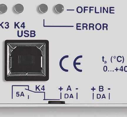
4 What is the standby wattage of the system? Standby power demand per DALI ECG 1-/2-lamp is 200 mw, for 3-/4-lamp it is 500 mw DALI PROFESSIONAL Controller CONT-4 incl. all DALI supplied couplers consumes W depending on the usage. The controller shows no real standby status because there are many processes in the background even if all ECGs are switched off by DALI. How can I integrate parallel a group of switching sensors? A) Electrical Solution 230V AC B) Software Solution in DALIpro GUI Put all switches into one function and define 'switch linkage' = parallel in Properties / General. Can I use other input devices than from OSRAM? Yes, the Siemens DALI Multi Sensor Office 5WG 141-2AB51 is electrical identical to OSRAM DALI Sensorcoupler. Only label and GTIN = EAN10 stored in the coupler are different. Also the Siemens DALI Pushbutton Coupler 5WG 141-2AB71 can be used in the OSRAM system. Is it possible to switch ON/OFF a CONT-4 controller relay K1 with a lightsensor? You cannot switch ON/OFF with OSRAM DALI Sensorcoupler because the lightsensor is only used for regulation. For switch function we use the PIR sensor with movement. But to generate a dusk / dawn switch here the trick : Use an external dawn sensor with switched output (must be dry contact, not mains connected) and take this as an input to DALI Pushbutton Coupler which is configured as switch. Can OSRAM DALI SWITCH SO be used with other systems than DALI PROFESSIONAL? OSRAM DALI SWITCH SO is not only made for use in DALI PROFESSIONAL. It is working similar to an ECG, means if a DALI controller sends a DALI command with dimmlevel > 1 all 3 relais switch ON, with dimmlevel = 0 they switch OFF. Which USB cable do I need to connect DALI PROFESSIONAL to PC? The connection from OSRAM DALI PROFESSIONAL Controller to PC is made with USB cable Typ A/B, see picture Usually a PC / notebook provides type A socket (rectangular connector, see left side of picture). The DALI controller USB input is type B (square connector, see right side of picture). What is a regulation factor? The regulation factor is a measure for the split of artificial / natural light in the room in relation to light sensor position. There are detailed algorithms behind and 2.8 is a standard value for an office. The regulation factor can be calibrated optional for each application, but this method is made for specialists which need extra accurate regulation. For standard use cases it is not necessary to calibrate the regualtion factor. ZPE EN Page 4 of 11

5 How many regulations can be used in the DALI PROFESSIONAL system? Up to 32 light regulations can be handled in a OSRAM DALI PROFESSIONAL controller CONT-4. If more light sensors are requested, up to 10 light sensors can be used together in one regulation. The according PIR sensors can be used seperately without restrictions. Many regulations running with fast changes at the same time can delay the reaction time. How can I sort all these many functions on the screen? Use up and down arrows on right upper Graph screen corner to move the selected function / group on the screen. Use subdivisions like rooms (zones) in the tree to get a better overview in large projects. What happens if a controller gets defect and how to replace? If a controller gets defect the DALI voltage is missing. With this all connected ECGs will show the System-Failure Mode which results by factory setting in 100% light. To replace the controller : install new controller, replace wiring 1:1 Open stored configuration from PC xxxx.osrdpc, upload to controller with The ECGs / DALI couplers keep their stored short address and with this all previous functions are copied to the correct devices. How can I reset the whole system to factory settings? Enter Plug&Play Mode by uploading an empty configuration to the controller. Then press on controller ON/OFF/DIM until POWER LED is blinking (approx. 10 s) - all coupler addresses are deleted. ECG addresses are not deleted with this reset. Do I need always a pushbutton controller to create a light regulation? If you start and stop the regulation with the PIR you need no pushbutton coupler. Here a configuration example where the light is on during occupancy and switches off after 20 minutes with non-occupancy : For practical reasons it is always an advantage if there are some additional pushbuttons to have a chance for manual control e.g. if PIR sensor gets defect / dirty / shielded... What is the max. adjustable delay time With DALIpro the maimum delay time between 2 actions is s = 100h which enables e.g. the configuration of a 100h burn-in for T5 fluorescent lamps. Is there a possibility to recall different scenes from external control systems? Scenes can be recalled externally if these are triggered via pushbutton coupler. One external output (relay dry contact) is necessary per scene or use of next scene action type. The scenes have to be configured before in the DALIpro setup. ZPE EN Page 5 of 11


6 DALI PROFESSIONAL INSTALLATION HINTS DALI wiring general 2 wires minimum 1.5 mm 2, max. 300 m, linear / star topology, basis insulation no mains voltage on DALI wires first solve wiring problems, then start setup procedure (to enable correct communication) Pushbutton Coupler wiring mains voltage on DALI wires can destroy the device max. 2 m cable to contact LED Check DALI line connection press once -> LED ON press again -> LED OFF DALI wire 1 here or here DALI wire 2 here or here internal shortcut for throughwiring option Sensor Coupler wiring Mains voltage on DALI wires can destroy the device 1 Sensor per Sensorcoupler distance lightsensor to measurement area 2..5 m DALI wire 1 here or here DALI wire 2 here or here internal shortcut for throughwiring option LED max. 5 m cable to Sensor Check DALI line connection press once -> LED ON press again -> LED OFF ZPE EN Page 6 of 11


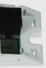
7 Installation Hints DALI Pushbutton Coupler Mounting Pushbutton Coupler do not install in cabinet with a long wiring to pushbuttons recommended for integration into wallbox and direct connection to DALI use only one coupler input per external button / switch ZPE EN Page 7 of 11


8 Installation Hints DALI Sensorcoupler Mounting of Sensorcoupler outside of a Luminaire with ECO CI KIT EAN Mounting of Sensor LS/PD outside of Luminaire Ceiling Integration LS/PD MULTI3 CI EAN Ceiling Mounting additional with SENSOR KIT EAN ZPE EN Page 8 of 11


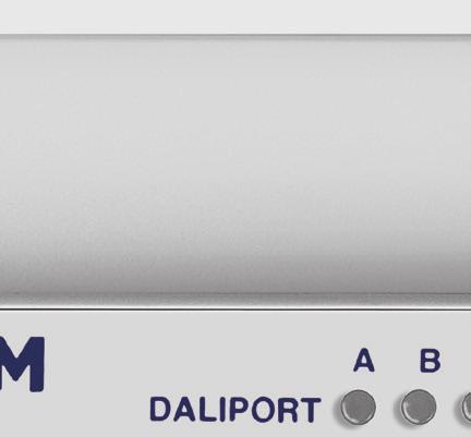
9 Application Hints DALI PROFESSIONAL Controller CONT-4 Firmware upgrade via DALIpro software Also possible on desk without mains voltage only supplied via USB Upgrade process finished -> Restart by mains voltage interruption + USB disconnection + restart software Operation modes without PC : Construction site mode for testing SELECT button for choice of DALIport / relay ON/OFF/DIM for TouchDIM functionality LED for visualisation of status (see manual) Plug&Play mode Toggle function for each button to all ECGs in the same DALI line (ON/OFF/DIM; TouchDIM functionality) Automatic occupancy detection with PIR of LS/PD Sensor / Sensorcoupler Switches On all ECGs in the same DALI line 5 minute off-delay when no more occupancy detected 5 minutes ZPE EN Page 9 of 11
 Real Time Clock")


10 Installation Hints Controller CONT-4 Install Circuit Breaker on DINrail beside Controller (for mains interruption at upgrade / reset) Real Time Clock Applications : Install external timer (clock) + pushbutton coupler to get time synchronized sequences started Timer Pushbutton Coupler for signal input DALI PROFESSIONAL - extended / wireless setup for transmission of the USB signal to LAN : BELKIN Network USB Hub F5L009 Wired Hi-Speed USB Device Server Gateway USB -> LAN to get WLAN access use in in combination with : DLINK DAP-1160 Wireless G Open Source Repeater Gateway LAN -> WLAN ZPE EN Page 10 of 11
11 DALI Professional System features with DALIpro Software Limits, maximum values per DALI PROFESSIONAL Controller CONT-4 4x maximum 64 ECG addresses 4x maximum 64 input device addresses (sensors / pushbuttons) Current limitation 200 ma per DALI port -> total limit of number of ECGs + input devices depending on mix 4x max. 300 m DALI line length, wires 1.5 mm 2 max. 5 m Sensor to Sensorcoupler max. 5 m Lightsensor distance to measurement area (depending on reflection characteristic) max. 2 m Pushbutton to Pushbutton Coupler 4x 16+ Groups, line overlapping allowed '+' means additional 'virtual' groups possible by software, but uses addressed commands Maximum number of groups only limited by controller memory 4x 16 Scenes, line overlapping allowed, but then one scene used for each line 4x 8 active light regulation loops more possible when noticeable delay accepted, limited by reaction times 4x switch-over relais maximum 5 A ohmic load each System Features out-of-the-box plug & play functionality if no configuration loaded full- and semi-automatic energy saver function with occupancy- and light-sensor up to 10 lightsensors / sensorcouplers per regulation corridor function with unlimited steps PIR disable / enable function sequences consisting of scenes, fade control, loops scene stepping visible ressource status message switch function e.g. for Highbay Sensor integration serial / parallel configuration of grouped switches programmable internal relay to be used in action list testfunction for all DALI devices configuration check against physical available devices simple 'failed ECG' replacement retrieve configuration by download from controller full project documentation in HTML file Perfect for industry hall warehouse classrooms single office large office meeting room corridor ZPE EN Page 11 of 11
DALI Professional Controller-4. Control unit Operating instructions
 LI Professional Controller-4 Control unit Operating instructions Contents Safety... 4 General instructions 4 Safety instructions 4 Description... 5 Purpose and application 5 Configuration 5 Design 5 Connections
OT EASY 60 II. LED control unit Operating instructions
 II LED control unit Operating instructions Contents Safety... 4 General instructions 4 Safety instructions 4 Intended use 4 Description... 5 Function and application 5 Function 5 Important definitions
Light is easy to control DALIeco: Multi-functional light management system for luminaire and ceiling integration Light is OSRAM
 www.osram.com/dalieco Light is easy to control : Multi-functional light management system for luminaire and ceiling integration Light is OSRAM System overview Intelligent and powerful light management
Light Management Systems:
 www.osram.com.au Light Management Systems: Complete LMS range for daylight-dependent and presence-dependent lighting. Energy Savings The complete LMS range for daylight-dependent and presence-dependent
Product and functional description
 Product and functional description Connection example The universal dimmer main module N 528/31 is an installation device for DIN-rail mounting, with N-system dimensions. It is designed for lighting control,
Operating instructions
 Operating instructions DALI BASIC lighting control system Type: DALI RC BASIC SO 24.05.2001 / V1.0 OSRAM GmbH Hellabrunner Str. 1 D 81536 Munich Tel.: +49 89 6213 0 Fax: +49 89 6213 2020 Customer Service
Tebis application software
 5 Tebis application software quicklink ON / OFF radio output products Electrical / Mechanical characteristics: see product information Product reference Product designation Application software ref. TP
Contents. GAMMA instabus Application program - Descriptions. June B0 KNX / DALI Gateway Twin N 141/
 Contents 1. Product description...2 1.1 DALI fundamentals...2 1.2 Gateway fundamentals...2 2. Functional overview...2 2.1 Modes... 3 2.1.1 Normal mode... 3 2.1.2 Standalone mode... 3 2.1.3 Direct mode...
DALI Link User Manual
 1.Overview Digital Addressable Lighting Interface (DALI) is a communication protocol for lighting control in buildings. The interface was first described in the IEC60929 standard for fluorescent lamp ballast,
KNX DALI Gateway Plus - User Manual
 KNX DALI Gateway Plus - User Manual Item No.: LC-013-064 1. Product Description The KNX DALI gateway Plus is the interface between the KNX installation and the DALI lighting system. It allows up to 64
Product data sheet: OTi DALI 25/ /700 LT2 G2
 www.osram.com Product data sheet: OTi DALI 25/220-240/700 LT2 G2 SELV Constant current LED driver Wide operating area up to 700mA - dimmable The reliable choice for the energy saving lighting: DALI dimmable,
LRI1655, LLC1655 Datasheet ActiLume 1-10V System
 1/6 Product details The ActiLume 1-10 V luminaire-based sensor enables daylight regulation and dimming when no presence is detected. The delay time can be customized between 1 and 30 minutes. The ActiLume
OSRAM LIGHTIFY TM Home. Professional
 OSRAM LIGHTIFY TM Home Professional OSR IQL PM-PL January 2015 LIGHTIFY TM Pro Introducing digital opportunities to analog devices Schematic overview of connected light: Cloud Internet Trad. Controls Non
1 Safety instructions. 2 Device components. 3 Function. IC00P01DAL - DALI gateway. DALI gateway. Operating instructions
 DALI gateway Operating instructions 1 Safety instructions Electrical equipment may only be installed and fitted by electrically skilled persons. Serious injuries, fire or property damage possible. Please
Application Manual TOUCH DIM CORRIDOR FUNCTION WIRELESS
 Application Manual TOUCH DIM CORRIDOR FUNCTION WIRELESS Contents Touch Dim Corridor function Wireless... 3 Touch Dim function description... 3 Touch Dim application areas... 3 Application examples... 4
Electrical devices may only be mounted and connected by electrically skilled persons.
 DALI gateway TW Art. No. : 2099REGHE Operating instructions 1 Safety instructions Electrical devices may only be mounted and connected by electrically skilled persons. Serious injuries, fire or property
AbstractAVR. Ledbuddy controller. Ledbuddy Panel User Manual 2009 Abstract AVR and Sabre Technology Tel:
 Ledbuddy Panel User Manual 2009 Abstract AVR and Sabre Technology Tel: 0116 278 8078 http://www.abstractavr.com AbstractAVR Ledbuddy controller Page 12 Introduction The LedBuddy is a simple yet powerful
WAGO Lighting Management The Lighting Control Solution Stay in Control of Your System
 WAGO Lighting Management The Lighting Control Solution Stay in Control of Your System OUR CONCEPT The Solution for Efficient Lighting Management in Production Facilities and Warehouses Using a combination
application software
 application software application software RF input product Electrical / Mechanical characteristics: see product user manual Product reference Product designation TP device RF devices 8565 52 xx 8565 62
Product and Applications Description. Note. Example of Operation. Installation Instructions. Application Programs WARNING
 Product and Applications Description Note If the application program is not loaded completely by the ETS, you had better interrupt the 24 V voltage supply of the I/O-module during the loading interval.
Lighting Control System for Indoor Applications LIGHT CONTROLLER LW RADIO-OPERATED VERSION ENOCEAN RADIO-OPERATED CONTROLLER
 LIGHT CONTROLLER LW RADIO-OPERATED VERSION ENOCEAN RADIO-OPERATED CONTROLLER The radio-operated module of the VS Light Controllers is based on the established EnOcean technology. Communication between
Modular Lighting Controls
 Lighting Controls CONTROLS IP20 Simple to install and set up, Modular Lighting Controls offer the opportunity to create individually tailored systems to meet the requirements of many types of applications.
Lighting Control System for Indoor Applications LIGHT CONTROLLER L LIGHT CONTROLLER L
 LIGHT CONTROLLER L LIGHT CONTROLLER L The VS Light Controllers are light management systems that were developed to control and regulate light independently of PCs and higher-order bus systems. Communication
OTi DALI 75/ /700 D LT2 UF L
 OTi DALI 75/220 240/700 D LT2 UF L OPTOTRONIC Intelligent Ultraflat Dimmable DALI Areas of application _ Linear lighting for office, education, industry, storage areas and retail _ Installation in emergency
Universal dim actuator 1gang RMD Universal dim actuator 2gang RMD Universal dim actuator 4gang RMD
 KNX Product documentation Universal dim actuator 1gang RMD Universal dim actuator 2gang RMD Universal dim actuator 4gang RMD Issue: 19.12.2012 Page 1 of 153 KNX Product documentation Contents 1 Product
The Energy Savers. Universal dimmer switches, capacity enhancer and 1-10V controllers. Selection table for universal dimmer switches,
 Universal dimmer switches, capacity enhancer and 1-10V controllers B The Energy Savers Selection table for universal dimmer switches, capacity enhancer and 1-10V controllers B0 Universal dimmer switch
Product and functional description
 Product and functional description The instabus / DAI gateway 141 is a KX EIB device with one DAI output to which up to 64 DAI actuators (e.g. DAI ballasts) can be connected to. It is not allowed to connect
Product and functional description
 Product and functional description Connection example The universal dimmer submodule N 528/41 is an installation device for DIN-rail mounting, with N-system dimensions. It is designed for lighting control,
SensaLink Programmer Instructions for Operation
 SensaLink Programmer Instructions for Operation Thorn Lighting Limited Merrington Lane Ind Est Spenneymoor Co. Durham SensaLink Programmer Handset Contents 1. Overview 2. Using the handset 3. Upgrading
Application description. KNX Push-button module 1gang. KNX Push-button module 2gang
 Application description KNX Push-button module 1/2gang Electrical/mechanical data: see the operating instructions for the product Order number Product designation Application programme TP product Radio
Lighting Controls and Connectivity scenecom. scenecom L, XL, XL EM and XL EM Bac scenecom Controller
 L, XL, XL EM and XL EM Bac Controller Product description Independent lighting control for up to 192 DALI control gears on 3 DALI lines Simple setup via WEB interface Cross DALI line control Freel programmable
AQStation Dimmer. Manual. LAN/Wi-Fi-based-control. Typ: AQS Dimmer black Order-No.: Typ: AQS Dimmer white Order-No.:
 AQStation Dimmer Typ: AQS Dimmer black Order-No.: 90.00.100 Typ: AQS Dimmer white Order-No.: 90.00.101 LAN/Wi-Fi-based-control Manual Altenburger Electronic GmbH Manual AQStation Dimmer V1.0-17.07.2015
Installation and User Guide
 D5 Installation and User Guide 8-Channel DALI Controller (478) Introduction The 478 is for controlling DALI ballasts, drivers and load interface units (except for the 490 Blinds Controller). Do not connect
Operating and mounting instructions
 General Usage IPAS DALI Gateways bring together the crossfunctional KNX installation bus and the lighting control specific DALI-Bus (IEC 60929). Lights with cost-effective, digital DALI ECGs can therefore
LINEAR LED DRIVERS. PrimeLine DALI dimmable. PrimeLine DALI DIMMABLE , , , , ,
 LINEAR LED DRIVERS PrimeLine DALI DIMMABLE 186445, 186446, 186575, 186576, 186577, 186578 Linear LED drivers with preset operating window or individual programming Typical Applications Built-in in linear
wdali MC Datenblatt Wireless DALI Multi Control Module wireless- control module for DALI circuits and four freely programmable switching inputs
 wdali MC Datenblatt Wireless DALI Multi Control Module wireless- control module for DALI circuits and four freely programmable switching inputs Art. Nr. 89453848 subject to change, Information provided
DALI 1Ch LED Dimmer CV
 DALI 1Ch LED Dimmer CV Datasheet Control Gear 1-channel LED Dimmer (CV, DT6) Art. Nr. 89453826 (4A) Art. Nr. 86459556 (8A) Art. Nr. 86459572 (10A) Art. Nr. 89453829 (16A) DALI 1Ch LED Dimmer CV DT6 2 DALI
KNX/EIB Flush-mounted universal dimming actuator 210 W. 1 Safety instructions. 2 Device components. Order-No. : Operating instructions
 Order-No. : 1058 00 Operating instructions 1 Safety instructions Electrical equipment may only be installed and fitted by electrically skilled persons. Failure to observe the instructions may cause damage
Product and functional description
 Product and functional description The RS 520/23 shutter / blind actuator is a KNX device with one relay output. The device is installed in an AP 118 Control Module Box or an AP 641 Room Control Box. The
Product and Applications Description. Application programs. instabus EIB Technical Product Information. February 2012
 Product and Applications Description Application programs UP 220/31 07 B0 S4 On-off-toggle/Dim/Shu/Value 982201 The push button interface UP 220/31 is a binary input and output devices for installation
Product and Function Description
 Product and Function Description and the LED display. The touchscreen can be used to select from up to 6 languages for the display of texts and messages. The room temperature controller integrated in Contouch
basicdim RCL Product manual (EN) PHASED OUT
 PHASED OUT") basicdim RCL Product manual (EN) PTA RBO LD E U CO T F NC AO MN TE EP NA TG SE T H E M E Table of contents Safety instructions................................................................. 2 Introduction.......................................................................
basicdim RCL Product manual (EN) PTA RBO LD E U CO T F NC AO MN TE EP NA TG SE T H E M E Table of contents Safety instructions................................................................. 2 Introduction.......................................................................
Operating Instructions. DALI-Gateway
 Operating Instructions 1. Safety instructions Electrical equipment must be installed and fitted by qualified electricians only. Failure to observe the instructions may cause damage to the device and result
Installation and User Guide. idim Remote Control (304) Product description
 Product description") Installation and User Guide idim Remote Control (0) Product description The idim Remote Control (0) can be used with the idim Sense Standalone to modify the preset light levels and recall/ store scenes,
Installation and User Guide idim Remote Control (0) Product description The idim Remote Control (0) can be used with the idim Sense Standalone to modify the preset light levels and recall/ store scenes,
Installation and Commissioning Instructions
 MR2500D / MR2500DF MR2500DALI / MR2500DALIF Mid Range Regulating LightSpot MR2500D MR2500DALI MR2500DF MR2500DALIF Installation and Commissioning Instructions Note: HP2000 required for commissioning Mid
DALI RM 8/16. Datasheet. DT7 Relay Module. Relay Module for the integration of non-dimmable ballasts in DALI lighting systems (DT7)
") RM 8/16 Datasheet DT7 Relay Module Relay Module for the integration of non-dimmable ballasts in lighting systems (DT7) Art. Nr. 86458629 (RM16) Art. Nr. 86458675 (RM8) Art. Nr. 86458629-DE (RM16-DE) Art.
RM 8/16 Datasheet DT7 Relay Module Relay Module for the integration of non-dimmable ballasts in lighting systems (DT7) Art. Nr. 86458629 (RM16) Art. Nr. 86458675 (RM8) Art. Nr. 86458629-DE (RM16-DE) Art.
Commissioning instructions
 Commissioning instructions corridorfunction 1 INTRODUCTION...2 2 INSTALLATION...2 2.1 CORRIDORFUNCTION WIRING DIAGRAM...3 3 COMMISSIONING IN GENERAL...3 4 ADJUSTMENT OF THE PROFILES...4 4.1 INDIVIDUAL
Helvar Designer 5 Foundation Course: Initial programming
 Helvar Designer 5 Foundation Course: Initial programming Edition 1 (10 th May 2018). Helvar Designer 5 Foundation Course: Initial Programming. Edition 1 Page 1 of 99 Contents A: BEFORE GOING ONLINE...
SWISS GARDE 360 HOKUSPOKUS KNX/KLR APPLICATION DESCRIPTION
 SWISS GARDE 360 HOKUSPOKUS KNX/KLR APPLICATION DESCRIPTION MODEL TYPE NO. SG HOKUSPOKUS KNX/KLR 25010 Program version 2.7 2012 M. Züblin AG Neue Winterthurerstrasse 30, 8304 Wallisellen, Switzerland The
Siemens Spares. RL 513D23 Switching actuator (relay), 3 x 6A. Technical Product Information
, 3 x 6A. Technical Product Information") Gamma instabus Technical Product Information RL 513D23 Switching actuator (relay), 3 x 6A 5WG1 513-4DB23 Switching actuator for independent switching of three lighting luminaire groups or other loads one
Gamma instabus Technical Product Information RL 513D23 Switching actuator (relay), 3 x 6A 5WG1 513-4DB23 Switching actuator for independent switching of three lighting luminaire groups or other loads one
Technical Manual. Light Controller L/LW. LiCS Light Controller L/LW EN 02/2014 I
 Technical Manual Light Controller L/LW Light Control Gear for Intelligent Indoor Lighting Light Controller L/LW Manual Version 12 For Software Version 13 LiCS Light Controller L/LW EN 02/2014 I wwwvossloh-schwabecom
Technical Manual MDT DaliControl IP Gateway w/ Webinterface
 05/2013 Technical Manual MDT DaliControl IP Gateway w/ Webinterface SCN-DALI64.02 1 Content 1 Content... 2 2 Overview... 5 2.1 Operation Instructions... 5 2.2 Usage & Handling... 6 2.3 Installation DaliControl
Fixture-Integrated Sensor based on Bluetooth mesh
 Fixture-Integrated Sensor based on Bluetooth mesh Converts uminaires into Multifunctional IoT Devices Bluetooth mesh 0-10V Dimming Control Motion Sensor Fixture Integration Ambient ight Sensor Autonomous
Use of the application program. Contents overview. Gamma instabus Application program description. November 2016
 Use of the application program Product family: Product type: Manufacturer: Application: Name: Description: Order no: Application: Name: Description: Order no: Lighting Dimmer Siemens Switch-/Dimming Actuator
CTRL DELTA WIRELESS CONTROL
 CTRL DELTA WIRELESS CONTROL CTRL DELTA WIRELESS CONTROL Delta Light introduces CTRL DELTA, a wireless dimming solution enabling you to control and manage a selection of luminaires via the CTRL DELTA app
Push Button Interface UP 220D31
 Product and Applications Description Application programs UP 220/31 07 B0 S4 On-off-toggle/Dim/Shu/Value 982203 The push button interface is a binary input and output devices for installation in in-wall
DALI RGBW LED Dimmer CC
 DALI RGBW LED Dimmer CC Datasheet Control Gear RGBW LED Dimmer (CC, DT8) common plus connector: Art. Nr. 86458912-100 (100mA) Art. Nr. 86458912-250 (250mA) Art. Nr. 86458912-350 (350mA) Art. Nr. 86458912-500
PHASED OUT. LED control gear Linear / area dimming. Uconverter LCAI 70 W 300 ma I010 one4all V ECO series
 Product description Dimmable built-in LED control gear for LED Constant current LED control gear with 00 ma output current Output power 0 W Nominal life-time of 50,000 h (at ta 50 C with a failure rate
GAMMA instabus Application Program Description. July CO Colour Touch-Panel
 Use of the application program Product family: Product type: Manufacturer: Name: Order no.: Name: Order no.: Display Display units Siemens UP 588/12 Colour Touch Panel UP 588/13 Colour Touch Panel (AC
DALI-2: Smart lighting control and interoperability
 DALI-2: Smart lighting control and interoperability Scott Wade, Technical & Certification Manager 18 th October 2018 1 Agenda Introduction, key facts & benefits DALI common misconceptions and comparisons
Contents. GAMMA instabus Application program description. August 2017
 Contents 1. Product description 4 1.1 DALI fundamentals... 4 1.2 Gateway fundamentals... 4 2. Functional overview of both devices 5 2.1 Modes... 5 2.2 Replace defective DALI-ECGs... 7 2.3 Failure messages
Content 1 Generally Installation...3
 Content 1 Generally...2 2 Installation...3 2.1 ETS App...3 2.2 Documentation and sample project...3 3 User interface...4 4 XLSX-Excel-Template...5 4.1 General...5 4.2 Mass operation...5 4.3 Errors during
RVL470. Heating controller. G2522en. Installation Instructions. 1 Installation. 2 Commissioning Wall mounting DIN rail mounting
 G2522en Heating controller Installation Instructions RVL470 1 Installation 1.1 Place of installation In a dry room, e.g. the boiler room Mounting choices: In a control panel (on the inner wall or on a
DALI 1Ch LED Dimmer CV
 1Ch ED Dimmer CV Datasheet Control Gear 1-channel ED Dimmer (CV, DT6) Art. r. 89453826 (4A) Art. r. 86459556 (8A) Art. r. 86459572 (10A) Art. r. 89453829 (16A) 1Ch ED Dimmer CV DT6 2 1Ch ED Dimmer CV Control
DALI RGBW LED Dimmer CV
 DALI RGBW LED Dimmer CV Datasheet Control Gear RGBW LED Dimmer (CV, DT8) Art. Nr. 86458509 (8A) Art. Nr. 89453840 (10A) Art. Nr. 89453843 (16A) Art. Nr. 89453843-HS (16A, dinrail) 2018/02/20, Lunatone
LRM2070, LRM2080, LRM2090 Datasheet OccuSwitch DALI sensor/controller
 1/15 General description 80 The OccuSwitch DALI is a combined sensor and controller. It will dim and switch on the lights in a room or area on occupancy and available daylight, with options for local override,
DALI RGB LED Dimmer CC
 DALI RGB LED Dimmer CC Datasheet Control Gear RGB LED Dimmer (CC, DT8) common plus connector: Art. Nr. 86458913-350 (350mA) Art. Nr. 86458913-500 (500mA) Art. Nr. 86458913-500 (700mA) common minus connector:
Colour Touch Panel 3.5
 Guangzhou Video-star Electronics Industrial Co., Ltd K-BUS R Colour Touch Panel 3.5 User manual-ver. 1.2 CHTF-35/01.1 CHTF-35/01.2.21 CHTF-35/01.2.22 CHTF-35/01.2.24 KNX/EIB Intelligent Installation Systems
Product and function description
 GAMMA instabus The following display and operating functions can be configured: switching, switching with forced control, dimming, sun protection control, recall and save scenes, sending and displaying
Product and Applications Description. Application Programs. Example of Operation. Installation Instructions. load circuit AC 230/400V L1 L2 L3 N
 Product and Applications Description Application Programs 20 A4 Binary 906401 4 binary outputs 1 status request available for each output 1 relation can be set allows 1 positive drive for each output initial
1 Safety instructions. 2 Intended use. 3 Product characteristics. 4 Operation. LB management. Universal rotary dimmer LED
 Art. no.: 1731DD Operating instructions 1 Safety instructions Electrical devices may only be mounted and connected by electrically skilled persons. Serious injuries, fire or property damage possible. Please
DALI RGBW LED Dimmer CV
 RGBW LED Dimmer CV Datasheet Control Gear RGBW LED Dimmer (CV, DT8) Art. Nr. 86458509 (8A) Art. Nr. 89453840 (10A) Art. Nr. 89453843 (16A) Art. Nr. 89453843-HS (16A, dinrail) 2018-08-27, Lunatone Industrielle
picture 1: Device components
 Art.-No.: 240-10 EB Operationsmanual 1 Safety instructions Electrical equipment may only be installed and fitted by electrically skilled persons. Failure to observe the instructions may cause damage to
Application description. Motion detector KNX- BCU
 Application description Motion detector KNX-BCU Electrical/mechanical data: see the operating instructions for the product Order number Product designation Application programme TP product Radio product
Connections, displays and operating elements
 KNX DALI gateway REG-K/1/16(64)/64MTN680191 Merten2005V6801-561-0007/08 GB KNX DALI gateway REG-K/1/16(64)/64 Operating instructions MTN680191 For your safety Connections, displays and operating elements
Use of the application program. Table of Contents. GAMMA instabus Application program description. April B0 CO Room Control Unit
 Use of the application program Product family: Product type: Manufacturer: Displays Display and operating units Siemens AG Name Room control unit UP 227 DELTA i-system Order no.: Table of Contents 5WG1
Data sheet. Function description. Benefits
 Function description To permit direct communication with the Philips SR interface, we offer two of our best and most innovative sensors: the ED PIR sensor with its patented multi-segment sensor lens and
DALI Wizard Analysis and commissioning tool for DALI installations ECG configuration tool Light is OSRAM
 www.osram.com DALI Wizard Analysis and commissioning tool for DALI installations ECG configuration tool Light is OSRAM Contents DALI Wizard... 1 Analysis and commissioning tool for DALI installations...
EY-EM : Remote I/O module, ecolink
 EY-EM 510...512: Remote I/O module, ecolink510...512 How energy efficiency is improved Optimum adjustment to applications by means of module technology. Reduction in wiring Features Part of the SAUTER
DALI Switch Cross. Datasheet. Multifunctional Switch Module. DALI control unit with four programmable momentary switches
 DALI Switch Cross Datasheet Multifunctional Switch Module DALI control unit with four programmable momentary switches Art. Nr. 86459793 (white) Art. Nr. 86459529 (black) subject to change, Information
Application Manual SPORTS HALLS
 Application Manual SPORTS HALLS Contents Sports halls... 3 Example 1: 3-zone sports hall... 3 Example 2: 2- zone sports hall... 7 Example 3: basic hall / multi-purpose hall... 11 Further Information...
Tebis application software
 5 Tebis application software SXB322AU V 1.x 2 inputs / 2-output module LED SXB344AU V 1.x 4 inputs / 4-output module LED Product reference Product designation TXB322AU TXB344AU Embedded module: 2 inputs
Lighting Controls and Connectivity DALI sensors. MSensor G3 SFI 30 PIR 5DPI WH/BK Multi-sensor
 MSensor G3 SFI 3 PIR 5DPI WH/BK Multi-sensor Product description Sensor developed to work with the latest DALI specification Monitoring of ambient light and motion detection Remote control interface allowing
1 Safety instructions. 2 Device components. 3 Function. Control unit 1-10 V, 3-gang. Art.-No.: 2193 REG. Operationsmanual
 Control unit 1-10 V, 3-gang Art.-No.: 2193 REG Operationsmanual 1 Safety instructions Electrical equipment may only be installed and fitted by electrically skilled persons. Failure to observe the instructions
Micro Smart Dimmer 2E manual. In-Wall Electrical Installation Instructions:
 Micro Smart Dimmer 2E manual The following instructions have been designed to assist in the installation of the Aeotec by Aeon Labs Z-Wave in wall Smart Dimmer. Please note that the instructions are for
The LED display (1) turns green when the load is switched on.
 turns green when the load is switched on.") Order no.: 2365 00 Operating instructions 1 Safety instructions Electrical devices may only be mounted and connected by electrically skilled persons. Serious injuries, fire or property damage possible.
Order no.: 2365 00 Operating instructions 1 Safety instructions Electrical devices may only be mounted and connected by electrically skilled persons. Serious injuries, fire or property damage possible.
Swiss Garde 360 PresenceDALI Master A-Comfort 24 m
 Installation instructions - Swiss Garde 360 Presence DALI Master A-Comfort m Art.-Nr. 750, 75, 76 - Edition 8-07 Swiss Garde 360 PresenceDALI Master A-Comfort m Edition UP Art.-Nr. 750, 75 360 H ca. 50%
PRESENCE DETECTOR, CONSTANT LIGHT CONTROLLER PD00D01KNX. Product Handbook
 PRESENCE DETECTOR, CONSTANT LIGHT CONTROLLER PD00D01KNX Product Handbook Product: PD00D01KNX Description: PRESENCE DETECTOR, CONSTANT CONTROLLER Document Version: 1.3 Date: 03/10/2017 Tribunale di Mila
LCC1653/01, LRI1653/01 ActiLume DALI System
 1/8 Product description The Philips ActiLume lighting control system consists of a small, lightweight sensor and controller, designed for easy integration into luminaires. ActiLume is a true Plug and Play
Wi-Fi Lighting Controls ELECTRONIC GMBH
 Wi-Fi Lighting Controls ELECTRONIC GMBH Contents The WiFi AQStation System Characteristics of the Wi-Fi AQStation System The AQStation Universal, Technical Data, wiring diagram AQStation Universal in combination
1 Safety instructions. 2 Device components. 3 Function. Control unit, 1-10 V 3-gang. Order-No. : Operating instructions
 Control unit, 1-10 V 3-gang Order-No. : 1019 00 Operating instructions 1 Safety instructions Electrical equipment may only be installed and fitted by electrically skilled persons. Failure to observe the
Application description. KNX push-button 1gang. KNX push-button 2gang. KNX push-button 3gang. KNX push-button 4gang. Page 1/51
 Application description KNX push-button 1, 2, 3 and 4gang Electrical/mechanical data: see the operating instructions for the product Order number Product designation Application programme TP product Radio
Technical Manual. KNX/DALI ACTUATOR 1x8 channels Art /70100
 KNX/DALI ACTUATOR 1x8 channels Art. 1630.04140/70100 DATEC ELECTRONIC AG Hochbergerstrasse 60C 4057 Basel Tel. +41 61 633 22 25, Fax. +41 61 633 22 27 www.datec.ch, support@datec.ch Because of continuous
Light is intelligent Lunis 2 micro controls.
 www.osram.com/lightingsolutions Light is intelligent Lunis 2 micro controls Modules for light management and emergency lighting with intelligent function and appealing design. Light is OSRAM Lunis 2 micro
DALI CW-WW LED Dimmer CC
 LED Dimmer CC Datasheet Control Gear DALI LED Dimmer (CC, DT8) for the control of tunable white luminaires (CW-WW) common plus connector: Art. Nr. 86458911-350 (350mA) Art.Nr. 86458911-350DE (350mA) Art.
SECTION DIGITAL LIGHTING CONTROLS
 SECTION 26 09 25 PART 1 - GENERAL 1.1 SUMMARY A. Work included: 1. General Performance 2. Digital Wall or Ceiling Mounted Occupancy Sensor System 3. Digital Wall Switches 4. Handheld Remote Controls 5.
Technical Manual. DALI GATEWAY Art A
 DALI GATEWAY Art. 119914 14783 003A TOTAL AUTOMATION GENERAL TRADING CO. LLC SUITE NO.506, LE SOLARIUM OFFICE TOWER, SILICON OASIS, DUBAI. UAE. Tel. +971 4 392 6860, Fax. +971 4 392 6850 www.tacdubai.com,
Casambi CBU-ASD. Bluetooth 4.0 Wireless Control Unit for LED Drivers. Features. 1 Description
 Casambi CBU-ASD Bluetooth 4.0 Wireless Control Unit for LED Drivers Features Wirelessly controllable with a smart device. No need for an external gateway device. Forms automatically a fast wireless mesh
An-10 Wireless Lighting Control
 Wireless Lighting Control The is a unique wireless system designed to control lighting. The can operate alone or be part of a new or existing lighting system. The creates unique benefits as the connection
picture 1: Device components
 Tronic rotary dimmer with soft-lock Order-No. : 2874 Operation- and Assembly Instructions 1 Safety instructions Electrical equipment may only be installed and fitted by electrically skilled persons. Failure