Embedded Systems UNIT 3
|
|
|
- Ella Poole
- 5 years ago
- Views:
Transcription
1 UNIT 3 UNIT- III Overview of Microcontroller and Embedded hardware and various building blocks, Processor Selection for an Embedded System, Interfacing Processor, Memories and I/O Devices, I/O Devices and I/O interfacing concepts, Timer and Counting Devices, Serial Communication and Advanced I/O, Buses between the Networked Multiple Devices.Embedded System Design and Co-design Issues in System Development Process, Design Cycle in the Development Phase for an Embedded System, Uses of Target System or its Emulator and In-Circuit Emulator (ICE), Use of Software Tools for Development of an Embedded System Design metrics of embedded systems - low power, high performance, engineering cost, time-to-market. Embedded hardware and various building blocks: The software embeds into hardware. Hardware consists of number of building blocks in a circuit board or in ASIC or on the SoC along with the processors. Hardware consists of following building blocks and devices in a system in general. 1. Power Source : Various units in an embedded system operate in one of the ranges 5.0V±0,25 V. 3_3 V ±0.3V 2.0 V ±0,2 V and 1.5V± 0 2V. 2. Clock Oscillator and Clocking Unit(s): The clock controls the time for executing an instruction,the frequency depends on the processor circuit execution rate. 3. System Timer: A timer circuit is suitably configured and functions as system dock. The system clock ticks and generates system-interrupts periodically. The system-clock interrupt enables execution of the system supervisory functions in the OS at the periodic intervals. System clock ticks can be 60 times in second. 4. Real-Time Clock (RTC): A real-time clock is required in a system. The clock drives the timers for various timing and counting needs in a system. The clock also updates time and date in the system. A microcontroller provides the timer circuits for the counting and tuning devices. 5. Reset Circuit, Power-up Reset and Watchdog-Timer Reset A circuit for reset enables restart of the system from the beginning using a switch or signal. The reset can also be performed by using an instruction to the processor. A power-up reset circuit enables restart of the system from beginning whenever power is switched on in the system. A watchdog-timer reset enables the restart of system when it is stuck up in certain set of instructions for a period more than preset time-interval. Reset based on reset-switch, reset-instruction or power-up or power-up reset and watchdog reset can be from same starting instruction or the different starting instructions. P a g e 1
 Internal RAM (b) Internal ROM/PROM/EPROM (c) External RAM for the temporary data and stack (in most systems) (d) Internal caches (in pipelined and superscalar")
 (h) RAM Memory buffers at the ports Fig.")
2 6. Memory Various forms of memories are used in a system. Figure shows a chart for the various forms of memories that are present in systems. These are as follows: (a) Internal RAM (b) Internal ROM/PROM/EPROM (c) External RAM for the temporary data and stack (in most systems) (d) Internal caches (in pipelined and superscalar microprocessors) (e) Internal EEPROM or flash (I) Memory Stick (card): video, images, songs, or speeches and large storage in digital camera, mobile systems (g) External ROM or PROM for embedding soft are (in almost all other than microcontrollers-based systems) (h) RAM Memory buffers at the ports Fig. The various forms of memory in the system Table gives the functions assigned in the embedded system to the memories, ROM or PROM or EPROM embeds the embedded software specific to the system. P a g e 2

3 A system embeds(locates) the following either in the internal ROM, PROM or in an external ROM or PROM of microcontroller; boot-up programs, initialization data, strings for an initial screen-display or initial state of the system, the programs for various tasks, ISRs and operating system kernel. The system has RAMs for saving temporary data, stack and buffers that are needed during a program run. The system also has flash for storing non-volatile results. 7 Input, Output and I/O Ports, I/O Buses and I/O interfaces The system gets inputs from physical devices through the input ports. Following are the examples A processor identifies each input port by its memory buffer address, called port address. Just as a memory location holding a byte or word is identified by an address, each input port is identified by the address. The system gets the inputs by the read operations at the port addresses. The system has output ports through which it sends output bytes to the real world. Each output port is identified by its memory-buffer address(es) called port address. The system sends the output by a write operation to the port address. There are also generalpurpose ports for both the input and output (I/O) operations. 8. Bus Processor of a system might have to be connected to a number of other devices and systems. A bus consists of a common set of lines to interconnect the multiple devices, hardware units and systems. It enables the communication between two units at any given instance. The remaining units remain in an in connected state during communication between these two. A bus communication protocol specifies the ways of communication of signals on the bus. At any instance, a pus may be a serial bus or a parallel bus transferring one bit or multiple data bits respectively. Protocol also specifies ways of arbitration when several devices need to communicate through the bus. Alternatively, protocol specifies ways of polling from each device for need of the bus at an instance. Protocol also specifies ways of daisy chaining the devices so that, at an instance, the bus is -anted to a device according to the device priority in the chain. P a g e 3
4 9. Digital to Analog conversion (ADC): DAC is a circuit that converts digital 8, 10 r 12 bits to analog output. A DAC operation is done with the help of a combination of the Pulse Width Modulation (PWM) unit in a microcontroller and an external integrator chip. 10. Analog to Digital Conversion (ADC): ADC is a circuit that converts the analog input to digital. The output is of 4, 8 10 or 12 bits from an ADC. Analog input is applied between + and pins. ADC circuit converts them into bits.the converted bits value depends on the reference voltage. When input +ve and -ve pins are at voltage equal to reference +ve and -ve voltage pins, then all output bits = 1. When the difference in voltage at inputs +ve and -ve pins = 0v then all output bits = 0. An ADC unit in the embedded system microcontroller may have multichannels. It can then take the inputs in succession from the various interconnected to different analog sources. 11. LED, LCD and Touch-Screen Displays: A system requires an interfacing circuit and software to display.led is used for indicating ON ststus of the system. A flashing LED may indicate that, a specific task is under completion or is running. It may indicate a wait status for a message.the display may show the status or message. Display may be a line display, a multiline display or a flashing display. An LSI (Lower scale integrated circuit) is used as display controller in case of the LCD matrix display. Touch screen is an input as well as output device, which is used by the user of a system to enter a command, choose a menu or to give user reply as input. The input is on physical touch as a screen position. The touch at a position is mostly by the finger or some times by stylus. Stylus is a thin pencil shaped long object. It is held between the fingers and used just as a pen to mark a dot. An LSI (Lower scale integrated circuit) functions as touch-screen controller. The display-screen display is similar to a computer display unit screen. 12. Keypad, Keyboard or Virtual Keypad at touch screen: The keypad or keyboard, is an important device for getting user inputs. A touch screen provides virtual keypad in a mobile computing system. Virtual keypad is a keypad displayed on displayed on the LCD display screen on touch plate. A user can enter the inputs using touches. A tile is displayed for a command on the LCD display screen. User can enter the command using touch at the tile. A keypad or keyboard may interface to a system. The system may provide necessary interfacing circuit and software to receive inputs directly from the keys or touch screen controller 13. Interrupt Handler: A system may process a number of devices. The system processor controls and handles the requirements of each device by running an appropriate ISR for each interrupting event, An interrupts-handling mechanism must exist in each system. It handles interrupts from various events or processors in the system. The system handled multiple interrupts, which may be simultaneously pending for service. P a g e 4
5 Processor Selection for an Embedded System: Processor Selection: Different systems require different features. A hardware designer takes these into view and selects an optimum performance-giving processor. A system designer uses the instruction cycle time as indicator to match the processor speed with the application. 1. A processor, which can operate at higher clock speed, processes more instructions per second. 2. A processor gives high computing performance when there exist 9a) Pipelines and superscalar architectures, (b) prefetch cache unit, caches, register files and MMU, and (c) RISC core architecture and most instructions of single clock cycle. 3. A processor with register windows provides fast context switching in a multitasking system. 4. Code-efficient instruction set and when needed dual 16/32 bit instructions set required for smaller memory needs and higher energy efficiency due to less number of memory fetches. 5. A power-efficient embedded system requires a processor that has auto shut-down feature for its units and programmability for disabling these when the processing need for a function or instruction set does not have constraint of execution time. It is also required to have Stop, Sleep and wait instructions. It may also require special cache design. 6. A processor with burst-mode access external memories fast, reads fast and writes fast. 7. It takes into account when considering a processor that an embedded system has to be energy efficient. A processor must have auto shutdown features in its various structural units when these are not employed during a particular time interval. Processor thus has high computing power at lower power dissipation Processor or Microcontroller Version Selection The processor and microcontroller selection process needs the following parameters: 1. Processor instruction cycle in jis (typical) 2. Internal bus width in Bits 3, CISC or RISC architecture 4. Pipeline and superscalar architecture 5. On-Chip RAM and/or register file bytes 6. instruction cache 7. Data cache 8. Program memory EPROM/EEPROM/Flash 9. Program memory capacity in bytes 10. Data/Stack memory capacity in bytes 11. Main memory Harvard or Princeton architecture P a g e 5
6 12. External interrupts 13. Bit manipulation instructions 14. Floating-point processor 15. Interrupt controller 16. DMA controller channels 17. On-chip MMU Microcontroller Version Selection: There are numerous versions of Additional devices and units arc provided in these versions. A version is selected for embedded system design as per the application as well as its cost. 1. An embedded system in automobile for example requires CAN bus. Then a version with CAN bus controller is selected. 2. An 8051 enhancement, 8052, has an additional timer. 3. Philips P83C528 has I 2 C serial bus. 4. The 8051-family member 83C152JA (and its sister JB., JC and JD) microcontrollers) have two direct memory access (DMA) channels on-chip. The K has a PTS (Peripheral Transactions Server) that supports DMA functions. [Only single and bulk transfer modes are supported, not the burst transfer mode] When a system requires direct transfer to memory from external systems, the DMAC is used so that the system performance improves by a separate processing unit for the data transfers nit and to the peripherals. Interfacing Processor, Memories and I/O Devices: Computer-System Buses: Bus is set of parallel lines (wires) which carry signals from one unit to another unit. Bus lines interconnect several units, but at a given instance, only two of them communicate. Bus enables interconnections among many units in a simple way. The signals are in specific sequences according to a method or protocol. Computing system buses are as follows: System Bus also called memory bus, which interconnects the subsystems. it interconnects the processor to memory system and other hardware units. This bus has high speed and bandwidth. It is according to the processor, memory system bandwidth, and for read-write cycles of instructions and data. (Bandwidth means number of bits transferred per second.) I/O Bus also called peripheral bus. interconnects the memory bus to a variable number of I/O devices functioning at variable speeds. Devices or peripherals are designed to interface to the I/O bus. The devices can be attached or withdrawn from the I/O bus at any time. CPU/Microprocessor System buses Computing system hardware consists of processor, memory and 1/O units (ports, devices and peripherals). System bus enables the P a g e 6

7 interconnections among multiple subsystems in the system CPU/microprocessor/processor in a computing system interconnects to memory, I/O units, devices and peripherals through a bus, called system bus or system memory bus. Three sets of signals classified as address bus, data bus and control bus define the system bus. A system-bus interfacing-design is according to the timing diagram oldie processor signals, bus bandwidth and word length. A simple structure of system bus is that same bus, which connects the memory also connects the other subs stems (I/O units. ports, devices and peripherals). Processor interfaces memory as well as I/O devices using system memory bus. Figure (a) shows the interfacing of processor, memory and I/O devices using memory system bus in a simple bus structure. 1. Address Bus Address bus signals are from processor to memory or other interfaced units. Address bus is unidirectional When it has n signals A0 to An-1, the Processor issues (send) addresses between 0 and 2 n -1 using the bus. The processor issues the address of the instruction byte or word to the memory system. The address bus communicates the address to the memory. The address bus of 32 bits fetches the instruction or data when an address specified by a 32-bit number, between 0 and Fig(a) Interfacing of processor, memory and I/O devices using memory system bus 2. Data Bus A data bus is bidirectional. If it has m bits then signals are D0-Dm-1 and processor reads a word or instruction or writes a word. Data signals are from processor to memory during read cycle and memory to processor during write cycle. A data bus of 8, 16, 32 or 64 bits fetches, loads, or stores the instruction or data. Read Cycle: Read cycle means a sequence of signals during which using the data-bus processor (i) fetches instruction from program-memory section of memory, or (ii) loads data word from data-memory section of memory. When the processor issues the address of the instruction. it gets back the instruction from memory through the data bus. When it issues the address of the data it processor loads the data through the data bus into a register. Write Cycle: Write cycle means a sequence of signals during which, using data bus, the processor sends data word to data-memory address in memory. When it issues the address of the data it stores the data in the memory through the data bus. P a g e 7
 When the processor issues the address, after allowing sufficient time for the set-up of all address bits, it also issues a memory-read control signal and waits for the data or instruction after a")
8 3. Control Bus A control bus issues signals to control the timing of various actions during communication of signals. These signals synchronize the subsystems. (a) When the processor issues the address, after allowing sufficient time for the set-up of all address bits, it also issues a memory-read control signal and waits for the data or instruction after a time interval. A memory unit must place the instruction or data during the interval in which memory-read signal is active (not inactivated by the processor). (b) When the processor issues the address on the address bus, and (after allowing sufficient time for the set-up of all address bits) it places the data on the data bus, it also then issues memory-write control signal (after allowing sufficient time for the set-up of all data bits) for store signal to memory. The memory unit must write (store) the data during the interval in which memory-write is active (not inactivated by the processor). I/O Devices and I/O interfacing concepts: Interfacing methods for I/O device: Fig(a) I/O devices and components interfacing circuit with ports P a g e 8

9 Method 1: I/O devices or components interface using ports, interfacing circuit consists of decoder. The decoder circuit connects the processor address bus and control signals. A port select output of the decoder is active when the address input corresponds to the port address. Interfacing circuit is designed as per available control signals and timing diagrams of the system bus signals. Fig(a) shows interface using ports. Fig(b) I/O devices and components interfacing circuit using I/O bus Method 2: A method is interfacing through an I/O bus. Interfacing circuit consists of I/O controller (called bridge or switch also). The switch circuit connects the processor and memory on system memory bus with the I/O bus. Interfacing-circuit is designed as per available control signals and timing diagrams of the system bus signals and I/O bus. Fig(b) shows interface using I/O bus and switch circuit between system memory bus and I?o bus. I/O managing data Memory mapped I/O and I/O mapped I/O operations are two types of operations based on processor and memory organisation. Memory mapped I/O is mapped into the same address space as program memory and/or user memory, and is accessed in the same way. Port mapped I/O uses a separate, dedicated address space and is accessed via a dedicated set of microprocessor instructions. P a g e 9

10 The difference between the two schemes occurs within the microprocessor. Intel has, for the most part, used the port mapped scheme for their microprocessors and Motorola has used the memory mapped scheme. As 16-bit processors have become obsolete and replaced with 32-bit and 64-bit in general use, reserving ranges of memory address space for I/O is less of a problem, as the memory address space of the processor is usually much larger than the required space for all memory and I/O devices in a system. Therefore, it has become more frequently practical to take advantage of the benefits of memory-mapped I/O. However, even with address space being no longer a major concern, neither I/O mapping method is universally superior to the other, and there will be cases where using port-mapped I/O is still preferable. Memory-mapped IO (MMIO): I/O devices are mapped into the system memory map along with RAM and ROM. To access a hardware device, simply read or write to those 'special' addresses using the normal memory access instructions. The advantage to this method is that every instruction which can access memory can be used to manipulate an I/O device. The disadvantage to this method is that the entire address bus must be fully decoded for every device. For example, a machine with a 32-bit address bus would require logic gates to resolve the state of all 32 address lines to properly decode the specific address of any device. This increases the cost of adding hardware to the machine. Port-mapped IO (PMIO or Isolated IO): I/O devices are mapped into a separate address space. This is usually accomplished by having a different set of signal lines to indicate a memory access versus a port access. The address lines are usually shared between the two address spaces, but less of them are used for accessing ports. An example of this is the standard PC which uses 16 bits of port address space, but 32 bits of memory address space. P a g e 10

11 The advantage to this system is that less logic is needed to decode a discrete address and therefore less cost to add hardware devices to a machine. On the older PC compatible machines, only 10 bits of address space were decoded for I/O ports and so there were only 1024 unique port locations; modern PC's decode all 16 address lines. To read or write from a hardware device, special port I/O instructions are used. From a software perspective, this is a slight disadvantage because more instructions are required to accomplish the same task. For instance, if we wanted to test one bit on a memory mapped port, there is a single instruction to test a bit in memory, but for ports we must read the data into a register, then test the bit. Memory-mapped IO Same address bus to address memory and I/O devices IO is treated as memory 16-bit addressing is used More decoder hardware is used Can access 2 16 = 64k locations theoretically Access to the I/O devices using regular instructions Memory instructions are used Arithmetic and logic operations can be performed directly on data Data transfer b/w register and I/O Port-mapped IO Different address spaces for memory and I/O devices IO is treated as IO 8-bit addressing is used Less decoder hardware is used Can address 2 16 =256 locations Uses a special class of CPU instructions to access I/O devices Special IN and OUT instructions Arithmetic and logic operations cannot be performed directly on data Data transfer b/w accumulator and I/O P a g e 11
12 I/O TYPES AND EXAMPLES: A port at a device can transmit (send) or receive through wire or wireless. Input port means a circuit to where bit or bits can be input (received) from an external device, peripheral or system. Output port means a circuit from where bit or bits can be output (sent) to an external device, peripheral or system. Input-Output (I/O) port means a circuit where bit(s) can be input or output. There are two types of I/Os, serial and parallel. Serial means in series of successive instants. Parallel means at the same instance. 1. Serial Input Serial input port means a circuit to where bits can be input (received) in successive time intervals. The time interval is known to the receiver port. The port assembles the bits on receiving at successive instances. 2. Serial Output Serial output port means a circuit from where bits can be output (sent) in successive time intervals. A time interval is known to the external device or system. The external device assembles the bits on receiving at successive instances from the output port. 3. Serial I/O Serial Input-Output (I/O) port means a circuit where serially received or sent bits can be input or output. 4. Parallel Input Parallel input port means a circuit where bits can be input (received) at an instant. The processor at the input device, circuit or system reads the bits from the port at next instant. 5. Parallel Output Parallel output port means a circuit from where bits can be output (sent) at an instant. The external trial device can read the bits at the output port. 6. Parallel I/O Parallel Input-Output (I/O) port means a circuit where received or sent bits in parallel can be input or output. 7. I/O Types (i) Serial Input, (ii) Synchronous Serial Output, (iii) Asynchronous Serial Input, (iv) Asynchronous Sena u..tput, (v) Parallel Port One-bit Input, (vi) Parallel Port One-bit Output, (vii) Parallel Port Input, and (viii) Parallel. Port Output. Synchronous serial input: The upper part of figure shows a synchronous input serial port at a device or system. Each bit in each byte is in synchronisation and each received byte is in synchronisation. Synchronisation means separation by a constant time interval or phase difference. A port (device) processing element reads a successive instances and saves each byte at a port buffer (register). Synchronous serial output: The middle part of Figure shows a synchronous output serial port. The serial port device optionally also sends the clock pulses at clock pin SCLK. Each bit in each byte is in synchronisation with a clock. The serial port at device optionally sends the clock pulses at SCLK pin. P a g e 12
 P a g")
13 Fig(1.a) P a g e 13
 and each bit in each byte is in synchronisation at output with the clock output (output).")
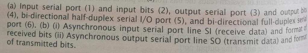
14 Synchronous Serial Input/Output: Figure at the left lower part shows a synchronous serial I/O port. Each bit in each byte is in synchronisation at input with a clock input (optional) and each bit in each byte is in synchronisation at output with the clock output (output). The bytes are sent or received at constant rates Asynchronous Serial Input: Figure (b) on the left side shows asynchronous input serial port line SI (receive data). Each bit is received in each byte at fixed intervals but each received byte need not be in synchronisation. The bytes can separate by the variable intervals or phase differences. Each bit at input port separates by T and bit transfer rate (for the serial line bits) is (1/T) baud per second (bps), but different bytes are received at varying intervals. Baud is taken from a German word for raindrops. Bytes pour from the sender like raindrops at irregular intervals. The sender does not send the clock pulses along with the hits. Asynchronous Serial Output: Figure (1.b) on the left side shows as output serial port line SO (transmit data). Each bit in each byte is at fixed intervals but each output byte need not in synchronisation (separates by a variable interval or phase difference). Fig(2) (a)m-bit parallel ports with m = 1,2, 7,8 (b) Two m/2 bit subsets for output bits in parallel. P a g e 14

15 Serial Communication and Advanced I/O: Refer 5 th unit Synchronous/Asynchronous Interfaces (like UART, SPI, I2C, and USB) topic Buses between the Networked Multiple Devices: A distributed networked system means a number of systems on a common bus or a set of buses, where each system interfaces to a bus. Each bus communicates as per a protocol. Bus communication simplifies the number of connections and provides a common way (protocol) of connecting different or same type of I/O devices. A communication system may use protocols such as UART, 12C, CAN, USB, Wi-Fi or Bluetooth for synchronous or asynchronous transmission from interface at device, or from the system to another interface. Figure 5.16 shows a computer-system bus connected to serial-i/o bus using a bus controller, and I/O bus networking the number of embedded systems distributed on a serial bus. I2C : Inter integrated circuit (I2C) is important serial communication protocol in modern electronic systems. Philips (now NXP semiconductors) invented this protocol in The objective of reducing the cost of production of television remote control motivated Philips to invent this protocol. I2C is a serial bus interface, can be implemented in software, but most of the microcontrollers support I2C by incorporating it as hard IP (Intellectual Property). IIC can be used to interface microcontroller with RTC, EEPROM and different variety of sensors. IIC is used to interface chips on motherboard, generally between a processor chip and any peripheral which supports I2C. I2C is very reliable wireline communication protocol for an on board or short distances. I2C is a serial protocol for two-wire interface to connect lowspeed devices like microcontrollers, EEPROMs, A/D and D/A converters, I/O interfaces and other similar peripherals in embedded systems. I2C combines the best features of SPI and UARTs. With I2C, you can connect multiple slaves to a single master (like SPI) and you can have multiple masters controlling single, or P a g e 15
 and Serial Clock Line (SCL). The reduction in number of pins in comparison with parallel data transfer is evident.")
16 multiple slaves. This is really useful when you want to have more than one microcontroller logging data to a single memory card or displaying text to a single LCD. I2C protocol uses two wires for data transfer between devices: Serial Data Line (SDA) and Serial Clock Line (SCL). The reduction in number of pins in comparison with parallel data transfer is evident. This reduces the cost of production, package size and power consumption. I2C is also best suited protocol for battery operated devices. I2C is also referred as two wire serial interface (TWI). SDA (Serial Data) The line for the master and slave to send and receive data. SCL (Serial Clock) The line that carries the clock signal. I2C is a serial communication protocol, so data is transferred bit by bit along a single wire (the SDA line). Like SPI, I2C is synchronous, so the output of bits is synchronized to the sampling of bits by a clock signal shared between the master and the slave. The clock signal is always controlled by the master. CAN: A number of devices located and are distributed in a Vehicular Control Network automobile uses a number of distributed embedded controllers. The controllers provide the controls for brakes, engines. electric power. lamps. temperature, air conditioning, car gate. front display panels. and cruising. P a g e 16
 shows six fields and interframe bits during a transfer of data bits on CAN bus, and timing formats and sequences of frame bits. The CAN has a serial line, which is bidirectional.")
17 The embedded controllers are networked and are controlled through a controller network bit. Figure (a) shows a network of number of CAN controllers and CAN devices on a CAN bus. Figure (b) shows six fields and interframe bits during a transfer of data bits on CAN bus, and timing formats and sequences of frame bits. The CAN has a serial line, which is bidirectional. A CAN device receives or sends a bit at an instance by operating at the maximum rate of 1Mbps. It employs a twisted pair connection to each node. The pair runs up to a maximum length of 40 m. A CAN version also functions up to 2Mbps. CAN (control area network) bus is a standard bus in distributed network. CAN is mainly used in automotive electronics. It is also used in medical electronics and industrial plant USB: Universal Serial Bus (USB) is a set of interface specifications for high speed wired communication between electronics systems peripherals and devices with or without PC/computer. The USB was originally developed in 1995 by many of the industry leading companies like Intel, Compaq, Microsoft, Digital, IBM, and Northern Telecom. The major goal of USB was to define an external expansion bus to add peripherals to a PC in easy and simple manner. USB offers users simple connectivity. It eliminates the mix of different connectors for different devices like printers, keyboards, mice, and other peripherals. That means USB-bus allows many peripherals to be connected using a single standardized interface socket. It supports all kinds of data, from slow mouse inputs to digitized audio and compressed video. P a g e 17

18 Various versions USB: USB1.0: USB 1.0 is the original release of USB having the capability of transferring 12Mbps, supporting up to 127 devices. This USB 1.0 specification model was introduced in January USB1.1: USB 1.1 came out in September USB 1.1 is also known as full-speed USB. This version is similar to the original release of USB; USB version 1.1 supported two speeds, a full speed mode of 12Mbits/s and a low speed mode of 1.5Mbits/s. USB2.0: Hewlett-Packard, Intel, LSI Corporation, Microsoft, NEC, and Philips jointly led the initiative to develop a higher data transfer rate than the 1.1 specifications. USB 2.0, also known as hi-speed USB. This hi-speed USB is capable of supporting a transfer rate of up to 480 Mbps, compared to 12 Mbps of USB 1.1. That's about 40 times as fast! USB3.0: It is also called as Super-Speed USB having a data transfer rate of 4.8Gbps(~5Gbps) That means it can deliver over 10x the speed of today's Hi-Speed USB connections USB 3.1 : is the latest version of USB also known as Super-Speed USB+, which having data transfer rate of 10Gbps. The USB system is made up of a host, multiple numbers of USB ports, and multiple peripheral devices connected in a tiered-star topology. USB can support 4 data transfer types or transfer modes. 1. Control 2. Isochronous 3. Bulk 4. Interrupt P a g e 18
19 Embedded System Design and Co-design Issues in System Development Process: There are two approaches for the embedded-system design. (1) The software development life cycle ends and the life cycle for the process of integrating the software into the hardware begin at the time when a system is designed. (2) Both cycles concurrently proceed when codesigning a time-critical sophisticated system. The final design, when implemented, gives the targeted embedded system, and thus the final product. Therefore, an understanding of the (a) software and hardware designs and integrating both into a system, and (b) hardware-software co-designing are important aspects of designing embedded systems. There is a hardware- software trade-off. The selection of the hardware during hardware design and an understanding of the possibilities and capabilities of hardware during software design are critical especially for a sophisticated embedded-system development. Choosing the Right Platform 1. Hardware- software trade-off -There is a trade-off between the hardware and software. It is possible that certain subsystems in hardware, I/O memory access, real-time clock, system clock, pulse-width modulation, timer, and serial communication are also implemented by the software. Hardware implementation provides the following advantages (i) Reduced memory for the program (ii)reduced Number of chips but an increased cost (iii) Simple coding for the device drivers (iv) Internally embedded codes, which are more secure than at the external ROM. Software implementation provides the following advantages: (i) Easier to change when new hardware versions become available (ii) Programmability for complex operations (iii) faster development time (iv) Modularity and portability (v) Use of a standard software-engineering model (vi) RTOS (vii) Faster speed of operation of complex functions with high-speed microprocessors (viii) Less cost for simple systems. 2. Choosing a Right Platform- System design of an embedded system also involves choosing a right platform. A platform consists of a number of following units. Processor, ASIP or ASSP, Multiple Processors, System-on-Chip, Memory Other Hardware Units of System, Buses, Software language, RTOS, Code generation tools, tools for finally embedding the software into binary image. 3. Embedded System Processors' Choice Processor-Less System -We have an alternative to a microprocessor microcontroller or DSP. Figure (a) shows the use of a PLC in place of a processor. We can use a PLC for the clothes-in clothes-out type system. A PLC fabricates by the programmable gates, PALs GALs, PLDs and CPLDs. P a g e 19

 -System with Microprocessor, Microcontroller or DSP System with Single-purpose Processor or ASSP in VLSI or FPGA Figure shows the processing of functions in using IP embedded into VLSI or")
20 Fig. (a) Use of a PLC in place of a processor (b) Use of a microprocessor, microcontroller or a DSP (c) Processing of functions by using IP embedded into the FPGA instead of processing by the ALU A PLC has very low operation speed. It also has a very low computational ability. It has very strong interfacing capability with its multiple inputs and outputs. It has system-specific programmability. it is simple in application. Its design implementation is also fast. Automatic chocolate-vending machine another exemplary application of PLC. Fig (b) -System with Microprocessor, Microcontroller or DSP System with Single-purpose Processor or ASSP in VLSI or FPGA Figure shows the processing of functions in using IP embedded into VLSI or FPGA instead of processing b the ALU A line of action in designing can be use of the IP, synthesising using V HDL like tool and embedding the synthesis into the FPGA. This FPGA implements the functions, which if implemented with the ALU and programmer coding will take a long time to develop. Factors and Needed Features Taken into Consideration- We consider a general. purpose processor choice or choose an ASIP (rnicrocontroller, DSP or network processor). the 32-hit system, 16 KB- on-chip memory. and need of cache, memory management unit, SIMD, M1MD or DSP instructions arise, we use a microprocessor or DSP. P a g e 20

21 Memory and Processor sensitive software Processor sensitive - A processor has different types of structural units. It can have memorymapped I/Os or 1/O-mapped I/Os. The I/O instructions are processor sensitive. A processor may be having fixed point ALU only. Floating-point operations, when needed. are handled differently than in a processor with floating-point operations. Memory sensitive - (i) An example of a memory-sensitive program is video processing and real-time video processing. The picture resolution actually used for processing and number of frames processed per second will depend upon the memory available as well as processor performance (ii) Memory address of I/O device registers, buffers, control-registers and vector addresses for the interrupt sources or source groups are prefixed in a microcontroller Memory-sensitive programs need to be optimized for the memory use by skilful programming. (iii) When using certain instruction sets like Thumb in ARM processor helps in 16-hit instructions, which save in less memory space than use of 32-bit ARM instruction set. Allocation of Addresses to memory, program segments and devices. 1.Functions, Processes, Data and stacks at the various segments of memory Program routines and processes can have different segments. Each segment has a pointer address and an offset address. Using offset, a code or data word is retrieved from a segment. A stack is a special data structure at the memory. It has a pointer address that always points to the top of a stack. This pointer address is called a stack pointer. The other data sets, which are also allotted memory are as following: String, Circular queue, A one-dimensional array, A table, A has table, Look-up tables, A list. 2 Device, Internal devices and I/O devices addresses and device drivers All I/O ports and devices have addresses. These are allocated to the devices according to the system processor and the system hardware configuration. Device addresses are used for processing by the driver. A device has an address, which is usually according to the system hardware or may also be the processor assigned ones. These addresses allocated to the following: 1. Device data Registers or RAM buffers 2. Device Control registers it saves control bits and may save configuration bits also. 3. Device status registers it saves flag bits as device ststus. A flag may include the need for servicing and show occurrence of a device-interrupt. P a g e 21

22 Porting issues of OS in an embedded platform The following porting issues may arise when the OS is used in an embedded platform: I/O instructions, Interrupt servicing routines, data types, interface specific data types, byte order, data alignment, linked lists, memory page size, time intervals. Design Cycle in the Development Phase for an Embedded System Unlike the design of a software application on a standard platform, the design of an embedded system implies that both software and hardware are being designed in parallel. Although this isn t always the case, it is a reality for many designs today. The profound implications of this simultaneous design process heavily influence how systems are designed. Figure shows the development process or an embedded system and Figure edit-test-debug cycle during implementation phase of the development process. There are cycles of editingtesting-debugging during the development phase, Whereas the processor part once chosen remains fixed, the application software codes have to be perfected by a number of runs and tests. Whereas the cost of the processor is quite small. The cost of developing a final targeted system is quite high and needs a larger time frame Man the hardware circuit design. The developer uses four main approaches to the edit-test-debug cycles. I. An IDE or prototype tool 2. A simulator without any hardware 3. Processor only at the target system and uses an in-between ICE (in-circuit-emulator). 4. Target system at the lest stage. P a g e 22

23 Uses of Target System or its Emulator and In-Circuit Emulator (ICE) An in-circuit emulator (ICE) is a hardware interface that allows a programmer to change or debug the software in an embedded system. The ICE is temporarily installed between the embedded system and an external terminal or personal computer so that the programmer can observe and alter what takes place in the embedded system, which has no display or keyboard of its own. An in-circuit emulator (ICE) provides a window into the embedded system. The programmer uses the emulator to load programs into the embedded system, run them, step through them slowly, and view and change data used by the system's software. An emulator gets its name because it emulates (imitates) the central processing unit (CPU) of the embedded system's computer. Traditionally it had a plug that inserts into the socket where the CPU integrated circuit chip would normally be placed. Most modern systems use the target system's CPU directly, with special JTAG-based debug access. Emulating the processor, or direct JTAG access to it, lets the ICE do anything that the processor can do, but under the control of a software developer. ICEs attach a computer terminal or personal computer (PC) to the embedded system. The terminal or PC provides an interactive user interface for the programmer to investigate and control the embedded system. For example, it is routine to have a source code level debugger with a graphical windowing interface that communicates through a JTAG adapter (emulator) to an embedded target system which has no graphical user interface. P a g e 23
24 Notably, when their program fails, most embedded systems simply become inert lumps of non-functioning electronics. Embedded systems often lack basic functions to detect signs of software failure, such as a memory management unit (MMU) to catch memory access errors. Without an ICE, the development of embedded systems can be extremely difficult, because there is usually no way to tell what went wrong. With an ICE, the programmer can usually test pieces of code, then isolate the fault to a particular section of code, and then inspect the failing code and rewrite it to solve the problem. In usage, an ICE provides the programmer with execution breakpoints, memory display and monitoring, and input/output control. Beyond this, the ICE can be programmed to look for any range of matching criteria to pause at, in an attempt to identify the origin of a failure. Most modern microcontrollers use resources provided on the manufactured version of the microcontroller for device programming, emulating, and debugging features, instead of needing another special emulation-version (that is, bond-out) of the target microcontroller.[1] Even though it is a cost-effective method, since the ICE unit only manages the emulation instead of actually emulating the target microcontroller, trade-offs must be made to keep prices low at manufacture time, yet provide enough emulation features for the (relatively few) emulation applications. Note: Debugging is the process of finding and resolving defects or problems within a computer program that prevent correct operation of computer software or a system. Use of Software Tools for Development of an Embedded System Refer 1 st unit topic Software Tools used for Development of an Embedded System Design metrics of embedded systems - low power, high performance, engineering cost, time-to-market Power dissipation For many systems, particularly battery operated systems, such as mobile phone or digital camera, the power consumed by the system is an important feature. The battery needs to be recharged less frequently if power dissipation is small. Performance Execution time taken by instructions in the system is a measure of performance. Smaller execution time for instructions means higher performance. For example, in a mobile phone, if the voice signals process between antenna and speaker in 0.1s, the the phone performance measure is o.1s. Consider another example, a digital camera if shoots and saves a still image of 4M pixels in 0.2s then the camera performance measure is 0.2s(=5 images per second). P a g e 24
25 Process deadlines Number of processes execute in the system. There are, for example, processes for keypad input processing, refresh of graphic display, and audio and video signals processing. Each process has a deadline within which each of them may be required to complete the computations and give the results. User Interfaces - User Interfaces, for example, user interactions through the keypad and display or GUIs or VUIs. Size - Size of system is measured in terms of (i) physical space required, (ii) RAM in KB and internal flash memory requirements in MB or GB for running software and storing the data, and (iii) number of million logic gates in the hardware. Engineering cost - Initial cost of developing, debugging and testing the hardware and software is called engineering cost. It is a one-time cost. It is therefore, called non-recurring engineering (NRE) cost. Manufacturing cost Cost of manufacturing each unit tor shipping. Total cost per unit is (NRE cost manufacturing cost for N units)/ N if N units are shipped. Flexibility - Flexibility in a design enables offering the different versions of a product without any significant change in engineering cost. Extra functions are necessitated by changing environment or software re-engineering. Software is enhanced for new version by adding the extra functions. The flexible design enables faster marketing. A manufacturer can offer the product in advanced versions later on easily and that too in shorter timeframes. Prototype development time - Time taken in days or months for developing the prototype and in-house testing for the system functionalities. It includes engineering time and prototyping time. Time-to-market - Time taken in days or months after prototype development to put a product for, users and consumers. System safety in terms of accidental tall from hand or table, theft (for phone locking ability and tracing ability), and in terms of user safety when using a product (for example. an automobile brake or engine) Maintenance - Maintenance means changeability and additions in the system, for example, adding or updating soft are. data and hardware. Example of software maintenance is additional set-. ice or functionality of software. Example of data maintenance is additional ring-tones, wallpapers, video-clips in a mobile phone or extending a card expiry-date in case of a smart card. Example of hardware maintenance is providing the additional memory or changing the memory stick in a mobile computer or digital camera. P a g e 25
Overview of Microcontroller and Embedded Systems
 UNIT-III Overview of Microcontroller and Embedded Systems Embedded Hardware and Various Building Blocks: The basic hardware components of an embedded system shown in a block diagram in below figure. These
Microprocessors/Microcontrollers
 Microprocessors/Microcontrollers A central processing unit (CPU) fabricated on one or more chips, containing the basic arithmetic, logic, and control elements of a computer that are required for processing
EMBEDDED SYSTEM BASICS AND APPLICATION
 EMBEDDED SYSTEM BASICS AND APPLICATION Dr.Syed Ajmal IIT- Robotics TOPICS TO BE DISCUSSED System Embedded System Components Classifications Processors Other Hardware Software Applications 2 INTRODUCTION
MLR INSTITUTE OF TECHNOLOGY DUNDIGAL , HYDERABAD QUESTION BANK
 MLR INSTITUTE OF TECHNOLOGY DUNDIGAL - 500 043, HYDERABAD QUESTION BANK Course Name : EMBEDDED SYSTEMS Course Code : A57043 Class : IV B. Tech I Semester Branch : ECE Year : 2015 2016 Course Faculty :
DEPARTMENT OF ELECTRICAL AND ELECTRONICS ENGINEERING EE6602- EMBEDDED SYSTEMS QUESTION BANK UNIT I - INTRODUCTION TO EMBEDDED SYSTEMS PART A
 DEPARTMENT OF ELECTRICAL AND ELECTRONICS ENGINEERING EE6602- EMBEDDED SYSTEMS QUESTION BANK UNIT I - INTRODUCTION TO EMBEDDED SYSTEMS PART A 1. Define system. A system is a way of working, organizing or
MICROPROCESSOR BASED SYSTEM DESIGN
 MICROPROCESSOR BASED SYSTEM DESIGN Lecture 5 Xmega 128 B1: Architecture MUHAMMAD AMIR YOUSAF VON NEUMAN ARCHITECTURE CPU Memory Execution unit ALU Registers Both data and instructions at the same system
Ali Karimpour Associate Professor Ferdowsi University of Mashhad
 AUTOMATIC CONTROL SYSTEMS Ali Karimpour Associate Professor Ferdowsi University of Mashhad Main reference: Christopher T. Kilian, (2001), Modern Control Technology: Components and Systems Publisher: Delmar
Computer Hardware Requirements for ERTSs: Microprocessors & Microcontrollers
 Lecture (4) Computer Hardware Requirements for ERTSs: Microprocessors & Microcontrollers Prof. Kasim M. Al-Aubidy Philadelphia University-Jordan DERTS-MSc, 2015 Prof. Kasim Al-Aubidy 1 Lecture Outline:
Ali Karimpour Associate Professor Ferdowsi University of Mashhad
 AUTOMATIC CONTROL SYSTEMS Ali Karimpour Associate Professor Ferdowsi University of Mashhad Main reference: Christopher T. Kilian, (2001), Modern Control Technology: Components and Systems Publisher: Delmar
The industrial technology is rapidly moving towards ARM based solutions. Keeping this in mind, we are providing a Embedded ARM Training Suite.
 EMBEDDED ARM TRAINING SUITE ARM SUITE INCLUDES ARM 7 TRAINER KIT COMPILER AND DEBUGGER THROUGH JTAG INTERFACE PROJECT DEVELOPMENT SOLUTION FOR ARM 7 e-linux LAB FOR ARM 9 TRAINING PROGRAM INTRODUCTION
Computer Hardware Requirements for Real-Time Applications
 Lecture (4) Computer Hardware Requirements for Real-Time Applications Prof. Kasim M. Al-Aubidy Computer Engineering Department Philadelphia University Real-Time Systems, Prof. Kasim Al-Aubidy 1 Lecture
Computer Organization and Microprocessors SYLLABUS CHAPTER - 1 : BASIC STRUCTURE OF COMPUTERS CHAPTER - 3 : THE MEMORY SYSTEM
 i SYLLABUS UNIT - 1 CHAPTER - 1 : BASIC STRUCTURE OF COMPUTERS Computer Types, Functional Units, Basic Operational Concepts, Bus Structures, Software, Performance, Multiprocessors and Multicomputers, Historical
ARM Processors for Embedded Applications
 ARM Processors for Embedded Applications Roadmap for ARM Processors ARM Architecture Basics ARM Families AMBA Architecture 1 Current ARM Core Families ARM7: Hard cores and Soft cores Cache with MPU or
ECE 1160/2160 Embedded Systems Design. Midterm Review. Wei Gao. ECE 1160/2160 Embedded Systems Design
 ECE 1160/2160 Embedded Systems Design Midterm Review Wei Gao ECE 1160/2160 Embedded Systems Design 1 Midterm Exam When: next Monday (10/16) 4:30-5:45pm Where: Benedum G26 15% of your final grade What about:
THE MICROCOMPUTER SYSTEM CHAPTER - 2
 THE MICROCOMPUTER SYSTEM CHAPTER - 2 20 2.1 GENERAL ASPECTS The first computer was developed using vacuum tubes. The computers thus developed were clumsy and dissipating more power. After the invention
EC EMBEDDED AND REAL TIME SYSTEMS
 EC6703 - EMBEDDED AND REAL TIME SYSTEMS Unit I -I INTRODUCTION TO EMBEDDED COMPUTING Part-A (2 Marks) 1. What is an embedded system? An embedded system employs a combination of hardware & software (a computational
4. Hardware Platform: Real-Time Requirements
 4. Hardware Platform: Real-Time Requirements Contents: 4.1 Evolution of Microprocessor Architecture 4.2 Performance-Increasing Concepts 4.3 Influences on System Architecture 4.4 A Real-Time Hardware Architecture
Components of a personal computer
 Components of a personal computer Computer systems ranging from a controller in a microwave oven to a large supercomputer contain components providing five functions. A typical personal computer has hard,
In this tutorial, we will discuss the architecture, pin diagram and other key concepts of microprocessors.
 About the Tutorial A microprocessor is a controlling unit of a micro-computer, fabricated on a small chip capable of performing Arithmetic Logical Unit (ALU) operations and communicating with the other
Understanding the basic building blocks of a microcontroller device in general. Knows the terminologies like embedded and external memory devices,
 Understanding the basic building blocks of a microcontroller device in general. Knows the terminologies like embedded and external memory devices, CISC and RISC processors etc. Knows the architecture and
The Central Processing Unit
 The Central Processing Unit All computers derive from the same basic design, usually referred to as the von Neumann architecture. This concept involves solving a problem by defining a sequence of commands
UNIT II PROCESSOR AND MEMORY ORGANIZATION
 UNIT II PROCESSOR AND MEMORY ORGANIZATION Structural units in a processor; selection of processor & memory devices; shared memory; DMA; interfacing processor, memory and I/O units; memory management Cache
Computers Are Your Future
 Computers Are Your Future Twelfth Edition Chapter 2: Inside the System Unit Copyright 2012 Pearson Education, Inc. Publishing as Prentice Hall 1 Inside the Computer System Copyright 2012 Pearson Education,
FIFTH SEMESTER DIPLOMA EXAMINATION IN ENGINEERING/ TECHNOLOGY-MARCH 2014 EMBEDDED SYSTEMS (Common for CT,CM) [Time: 3 hours] (Maximum marks : 100)
![FIFTH SEMESTER DIPLOMA EXAMINATION IN ENGINEERING/ TECHNOLOGY-MARCH 2014 EMBEDDED SYSTEMS (Common for CT,CM) [Time: 3 hours] (Maximum marks : 100)](/thumbs/76/73351884.jpg "FIFTH SEMESTER DIPLOMA EXAMINATION IN ENGINEERING/ TECHNOLOGY-MARCH 2014 EMBEDDED SYSTEMS (Common for CT,CM) [Time: 3 hours] (Maximum marks : 100)") (Revision-10) FIFTH SEMESTER DIPLOMA EXAMINATION IN ENGINEERING/ TECHNOLOGY-MARCH 2014 EMBEDDED SYSTEMS (Common for CT,CM) [Time: 3 hours] (Maximum marks : 100) PART-A (Maximum marks : 10) I. Answer all
(Revision-10) FIFTH SEMESTER DIPLOMA EXAMINATION IN ENGINEERING/ TECHNOLOGY-MARCH 2014 EMBEDDED SYSTEMS (Common for CT,CM) [Time: 3 hours] (Maximum marks : 100) PART-A (Maximum marks : 10) I. Answer all
Architecture of Computers and Parallel Systems Part 6: Microcomputers
 Architecture of Computers and Parallel Systems Part 6: Microcomputers Ing. Petr Olivka petr.olivka@vsb.cz Department of Computer Science FEI VSB-TUO Architecture of Computers and Parallel Systems Part
3.1 Description of Microprocessor. 3.2 History of Microprocessor
 3.0 MAIN CONTENT 3.1 Description of Microprocessor The brain or engine of the PC is the processor (sometimes called microprocessor), or central processing unit (CPU). The CPU performs the system s calculating
Product Technical Brief S3C2440X Series Rev 2.0, Oct. 2003
 Product Technical Brief S3C2440X Series Rev 2.0, Oct. 2003 S3C2440X is a derivative product of Samsung s S3C24XXX family of microprocessors for mobile communication market. The S3C2440X s main enhancement
Microcontroller basics
 FYS3240 PC-based instrumentation and microcontrollers Microcontroller basics Spring 2017 Lecture #4 Bekkeng, 30.01.2017 Lab: AVR Studio Microcontrollers can be programmed using Assembly or C language In
 Accessing I/O Devices Interface to CPU and Memory Interface to one or more peripherals Generic Model of IO Module Interface for an IO Device: CPU checks I/O module device status I/O module returns status
Chapter 4. Enhancing ARM7 architecture by embedding RTOS
 Chapter 4 Enhancing ARM7 architecture by embedding RTOS 4.1 ARM7 architecture 4.2 ARM7TDMI processor core 4.3 Embedding RTOS on ARM7TDMI architecture 4.4 Block diagram of the Design 4.5 Hardware Design
Introduction to Microcontrollers
 Introduction to Microcontrollers Embedded Controller Simply an embedded controller is a controller that is embedded in a greater system. One can define an embedded controller as a controller (or computer)
CHAPTER 4 MARIE: An Introduction to a Simple Computer
 CHAPTER 4 MARIE: An Introduction to a Simple Computer 4.1 Introduction 177 4.2 CPU Basics and Organization 177 4.2.1 The Registers 178 4.2.2 The ALU 179 4.2.3 The Control Unit 179 4.3 The Bus 179 4.4 Clocks
MicroProcessor. MicroProcessor. MicroProcessor. MicroProcessor
 1 2 A microprocessor is a single, very-large-scale-integration (VLSI) chip that contains many digital circuits that perform arithmetic, logic, communication, and control functions. When a microprocessor
Babu Madhav Institute of Information Technology, UTU
 Course: 060010901 Embedded System Unit 1 Introduction to Embedded System SHORT QUESTIONS: 1. What is an embedded system? 2. State the definition of embedded system given by Wayne Wolf. 3. State the full
BASIC INTERFACING CONCEPTS
 Contents i SYLLABUS UNIT - I 8085 ARCHITECTURE Introduction to Microprocessors and Microcontrollers, 8085 Processor Architecture, Internal Operations, Instructions and Timings, Programming the 8085-Introduction
D Demonstration of disturbance recording functions for PQ monitoring
 D6.3.7. Demonstration of disturbance recording functions for PQ monitoring Final Report March, 2013 M.Sc. Bashir Ahmed Siddiqui Dr. Pertti Pakonen 1. Introduction The OMAP-L138 C6-Integra DSP+ARM processor
ATmega128. Introduction
 ATmega128 Introduction AVR Microcontroller 8-bit microcontroller released in 1997 by Atmel which was founded in 1984. The AVR architecture was conceived by two students (Alf-Egil Bogen, Vergard-Wollen)
Chapter 5 - Input / Output
 Chapter 5 - Input / Output Luis Tarrataca luis.tarrataca@gmail.com CEFET-RJ L. Tarrataca Chapter 5 - Input / Output 1 / 90 1 Motivation 2 Principle of I/O Hardware I/O Devices Device Controllers Memory-Mapped
Segment 1A. Introduction to Microcomputer and Microprocessor
 Segment 1A Introduction to Microcomputer and Microprocessor 1.1 General Architecture of a Microcomputer System: The term microcomputer is generally synonymous with personal computer, or a computer that
Homeschool Enrichment. The System Unit: Processing & Memory
 Homeschool Enrichment The System Unit: Processing & Memory Overview This chapter covers: How computers represent data and programs How the CPU, memory, and other components are arranged inside the system
Interrupt/Timer/DMA 1
 Interrupt/Timer/DMA 1 Exception An exception is any condition that needs to halt normal execution of the instructions Examples - Reset - HWI - SWI 2 Interrupt Hardware interrupt Software interrupt Trap
Introduction to ARM LPC2148 Microcontroller
 Introduction to ARM LPC2148 Microcontroller Dr.R.Sundaramurthy Department of EIE Pondicherry Engineering College Features of LPC2148 in a Nut Shell CPU = ARM 7 Core Word Length = 32 Bit ROM = 512 KB RAM
Product Technical Brief S3C2413 Rev 2.2, Apr. 2006
 Product Technical Brief Rev 2.2, Apr. 2006 Overview SAMSUNG's is a Derivative product of S3C2410A. is designed to provide hand-held devices and general applications with cost-effective, low-power, and
Product Technical Brief S3C2412 Rev 2.2, Apr. 2006
 Product Technical Brief S3C2412 Rev 2.2, Apr. 2006 Overview SAMSUNG's S3C2412 is a Derivative product of S3C2410A. S3C2412 is designed to provide hand-held devices and general applications with cost-effective,
Tutorial Introduction
 Tutorial Introduction PURPOSE: This tutorial describes the key features of the DSP56300 family of processors. OBJECTIVES: Describe the main features of the DSP 24-bit core. Identify the features and functions
Chapter 7: Processor and Memory
 Slide 1/27 Learning Objectives In this chapter you will learn about: Internal structure of processor Memory structure Determining the speed of a processor Different types of processors available Determining
Microcontrollers. Microcontroller
 Microcontrollers Microcontroller A microprocessor on a single integrated circuit intended to operate as an embedded system. As well as a CPU, a microcontroller typically includes small amounts of RAM and
Introduction to Embedded Systems
 Introduction to Embedded Systems Minsoo Ryu Hanyang University Outline 1. Definition of embedded systems 2. History and applications 3. Characteristics of embedded systems Purposes and constraints User
Embedded Systems Design (630414) Lecture 1 Introduction to Embedded Systems Prof. Kasim M. Al-Aubidy Computer Eng. Dept.
 Lecture 1 Introduction to Embedded Systems Prof. Kasim M. Al-Aubidy Computer Eng. Dept.") Embedded Systems Design (630414) Lecture 1 Introduction to Embedded Systems Prof. Kasim M. Al-Aubidy Computer Eng. Dept. Definition of an E.S. It is a system whose principal function is not computational,
Embedded Systems Design (630414) Lecture 1 Introduction to Embedded Systems Prof. Kasim M. Al-Aubidy Computer Eng. Dept. Definition of an E.S. It is a system whose principal function is not computational,
VALLIAMMAI ENGINEERING COLLEGE
 VALLIAMMAI ENGINEERING COLLEGE SRM Nagar, Kattankulathur 603 203 DEPARTMENT OF ELECTRONICS AND INSTRUMENTATION ENGINEERING QUESTION BANK VI SEMESTER EE6602 EMBEDDED SYSTEMS Regulation 2013 Academic Year
Intelop. *As new IP blocks become available, please contact the factory for the latest updated info.
 A FPGA based development platform as part of an EDK is available to target intelop provided IPs or other standard IPs. The platform with Virtex-4 FX12 Evaluation Kit provides a complete hardware environment
Introduction to the Personal Computer
 Introduction to the Personal Computer 2.1 Describe a computer system A computer system consists of hardware and software components. Hardware is the physical equipment such as the case, storage drives,
e-pg Pathshala Subject: Computer Science Paper: Embedded System Module: Embedded System Design Case Study-Part I Module No: CS/ES/39 Quadrant 1 e-text
 e-pg Pathshala Subject: Computer Science Paper: Embedded System Module: Embedded System Design Case Study-Part I Module No: CS/ES/39 Quadrant 1 e-text In this lecture, the design and the basic concepts
Q1. Describe C.P.U and its subunits with the help of diagram?
 Q1. Describe C.P.U and its subunits with the help of diagram? Ans. C.P.U (CENTRAL PROCESSING UNIT) Book page # 27 The C.P.U is the brain of computer.it controls and supervises all the units. Processing
Input/Output Problems. External Devices. Input/Output Module. I/O Steps. I/O Module Function Computer Architecture
 168 420 Computer Architecture Chapter 6 Input/Output Input/Output Problems Wide variety of peripherals Delivering different amounts of data At different speeds In different formats All slower than CPU
MT2 Introduction Embedded Systems. MT2.1 Mechatronic systems
 MT2 Introduction Embedded Systems MT2.1 Mechatronic systems Mechatronics is the synergistic integration of mechanical engineering, with electronics and intelligent computer control in the design and manufacturing
Generic Model of I/O Module Interface to CPU and Memory Interface to one or more peripherals
 William Stallings Computer Organization and Architecture 7 th Edition Chapter 7 Input/Output Input/Output Problems Wide variety of peripherals Delivering different amounts of data At different speeds In
7/28/ Prentice-Hall, Inc Prentice-Hall, Inc Prentice-Hall, Inc Prentice-Hall, Inc Prentice-Hall, Inc.
 Technology in Action Technology in Action Chapter 9 Behind the Scenes: A Closer Look a System Hardware Chapter Topics Computer switches Binary number system Inside the CPU Cache memory Types of RAM Computer
Lecture 2 Microcomputer Organization: Fig.1.1 Basic Components of Microcomputer
 Lecture 2 Microcomputer Organization: As discussed in previous lecture microprocessor is a central processing unit (CPU) with its related timing functions on a single chip. A microprocessor combined with
MICROPROCESSOR AND MICROCONTROLLER BASED SYSTEMS
 MICROPROCESSOR AND MICROCONTROLLER BASED SYSTEMS UNIT I INTRODUCTION TO 8085 8085 Microprocessor - Architecture and its operation, Concept of instruction execution and timing diagrams, fundamentals of
Raspberry Pi - I/O Interfaces
 ECE 1160/2160 Embedded Systems Design Raspberry Pi - I/O Interfaces Wei Gao ECE 1160/2160 Embedded Systems Design 1 I/O Interfaces Parallel I/O and Serial I/O Parallel I/O: multiple input/output simultaneously
Pharmacy college.. Assist.Prof. Dr. Abdullah A. Abdullah
 The kinds of memory:- 1. RAM(Random Access Memory):- The main memory in the computer, it s the location where data and programs are stored (temporally). RAM is volatile means that the data is only there
ECE332, Week 2, Lecture 3. September 5, 2007
 ECE332, Week 2, Lecture 3 September 5, 2007 1 Topics Introduction to embedded system Design metrics Definitions of general-purpose, single-purpose, and application-specific processors Introduction to Nios
ECE332, Week 2, Lecture 3
 ECE332, Week 2, Lecture 3 September 5, 2007 1 Topics Introduction to embedded system Design metrics Definitions of general-purpose, single-purpose, and application-specific processors Introduction to Nios
Infineon C167CR microcontroller, 256 kb external. RAM and 256 kb external (Flash) EEPROM. - Small single-board computer (SBC) with an
 EEPROM. - Small single-board computer (SBC) with an") Microcontroller Basics MP2-1 week lecture topics 2 Microcontroller basics - Clock generation, PLL - Address space, addressing modes - Central Processing Unit (CPU) - General Purpose Input/Output (GPIO)
Microcontroller Basics MP2-1 week lecture topics 2 Microcontroller basics - Clock generation, PLL - Address space, addressing modes - Central Processing Unit (CPU) - General Purpose Input/Output (GPIO)
Module 1. Introduction. Version 2 EE IIT, Kharagpur 1
 Module 1 Introduction Version 2 EE IIT, Kharagpur 1 Lesson 4 Embedded Systems Components Part II Version 2 EE IIT, Kharagpur 2 Overview on Components Instructional Objectives After going through this lesson
Computer Organization
 INF 101 Fundamental Information Technology Computer Organization Assistant Prof. Dr. Turgay ĐBRĐKÇĐ Course slides are adapted from slides provided by Addison-Wesley Computing Fundamentals of Information
Basic Components of Digital Computer
 Digital Integrated Circuits & Microcontrollers Sl. Mihnea UDREA, mihnea@comm.pub.ro Conf. Mihai i STANCIU, ms@elcom.pub.ro 1 Basic Components of Digital Computer CPU (Central Processing Unit) Control and
Copyright 2016 Xilinx
 Zynq Architecture Zynq Vivado 2015.4 Version This material exempt per Department of Commerce license exception TSU Objectives After completing this module, you will be able to: Identify the basic building
Computer Systems. Communication (networks, radio links) Meatware (people, users don t forget them)
 Meatware (people, users don t forget them)") Computers are useful machines, but they are generally useless by themselves. Computers are usually part of a system a computer system includes: Hardware (machines) Software (programs, applications) Communication
Computers are useful machines, but they are generally useless by themselves. Computers are usually part of a system a computer system includes: Hardware (machines) Software (programs, applications) Communication
ARM Cortex core microcontrollers 3. Cortex-M0, M4, M7
 ARM Cortex core microcontrollers 3. Cortex-M0, M4, M7 Scherer Balázs Budapest University of Technology and Economics Department of Measurement and Information Systems BME-MIT 2018 Trends of 32-bit microcontrollers
Instruction Register. Instruction Decoder. Control Unit (Combinational Circuit) Control Signals (These signals go to register) The bus and the ALU
 Control Signals (These signals go to register) The bus and the ALU") Hardwired and Microprogrammed Control For each instruction, the control unit causes the CPU to execute a sequence of steps correctly. In reality, there must be control signals to assert lines on various
Hardwired and Microprogrammed Control For each instruction, the control unit causes the CPU to execute a sequence of steps correctly. In reality, there must be control signals to assert lines on various
MA Unit 4. Question Option A Option B Option C Option D
 Matoshri College of Engineering & Research Centre Nashik Department of Computer Engineering Class :- Second Year Computer Engineering Sem - 1 Subject :- MICROPROCESSOR ARCHITECTURE UNIT-IV 1 Accumulator
Organisasi Sistem Komputer
 LOGO Organisasi Sistem Komputer OSK 5 Input Output 1 1 PT. Elektronika FT UNY Input/Output Problems Wide variety of peripherals Delivering different amounts of data At different speeds In different formats
USB for Embedded Devices. Mohit Maheshwari Prashant Garg
 USB for Embedded Devices Mohit Maheshwari 200601008 Prashant Garg 200601144 USB : An Introduction The Universal Serial Bus (USB) is a specification developed by Compaq, Intel, Microsoft and NEC, joined
Embedded Systems: Hardware Components (part II) Todor Stefanov
 Todor Stefanov") Embedded Systems: Hardware Components (part II) Todor Stefanov Leiden Embedded Research Center, Leiden Institute of Advanced Computer Science Leiden University, The Netherlands Outline Generic Embedded
Embedded Systems: Hardware Components (part II) Todor Stefanov Leiden Embedded Research Center, Leiden Institute of Advanced Computer Science Leiden University, The Netherlands Outline Generic Embedded
EE 308: Microcontrollers
 EE 308: Microcontrollers AVR Architecture Aly El-Osery Electrical Engineering Department New Mexico Institute of Mining and Technology Socorro, New Mexico, USA January 23, 2018 Aly El-Osery (NMT) EE 308:
Introduction to Embedded Systems
 Introduction to Embedded Systems Outline Embedded systems overview What is embedded system Characteristics Elements of embedded system Trends in embedded system Design cycle 2 Computing Systems Most of
Interconnects, Memory, GPIO
 Interconnects, Memory, GPIO Dr. Francesco Conti f.conti@unibo.it Slide contributions adapted from STMicroelectronics and from Dr. Michele Magno, others Processor vs. MCU Pipeline Harvard architecture Separate
Embedded Systems Dr. Santanu Chaudhury Department of Electrical Engineering Indian Institute of Technology, Delhi. Lecture - 10 System on Chip (SOC)
") Embedded Systems Dr. Santanu Chaudhury Department of Electrical Engineering Indian Institute of Technology, Delhi Lecture - 10 System on Chip (SOC) In the last class, we had discussed digital signal processors.
Embedded Systems Dr. Santanu Chaudhury Department of Electrical Engineering Indian Institute of Technology, Delhi Lecture - 10 System on Chip (SOC) In the last class, we had discussed digital signal processors.
MICROPROCESSOR SYSTEM FOR VISUAL BAKED PRODUCTS CONTROL
 MICROPROCESSOR SYSTEM FOR VISUAL BAKED PRODUCTS CONTROL Krassimir Kolev, PhD University of Food Technologies - Plovdiv, Bulgaria Abstract The paper reports an authentic solution of a microprocessor system
OPERATING SYSTEMS CS136
 OPERATING SYSTEMS CS136 Jialiang LU Jialiang.lu@sjtu.edu.cn Based on Lecture Notes of Tanenbaum, Modern Operating Systems 3 e, 1 Chapter 5 INPUT/OUTPUT 2 Overview o OS controls I/O devices => o Issue commands,
CREATED BY M BILAL & Arslan Ahmad Shaad Visit:
 CREATED BY M BILAL & Arslan Ahmad Shaad Visit: www.techo786.wordpress.com Q1: Define microprocessor? Short Questions Chapter No 01 Fundamental Concepts Microprocessor is a program-controlled and semiconductor
PD215 Mechatronics. Week 3/4 Interfacing Hardware and Communication Systems
 PD215 Mechatronics Week 3/4 Interfacing Hardware and Communication Systems Interfacing with the physical world A compute device (microprocessor) in mechatronic system needs to accept input information
DQ8051. Revolutionary Quad-Pipelined Ultra High performance 8051 Microcontroller Core
 DQ8051 Revolutionary Quad-Pipelined Ultra High performance 8051 Microcontroller Core COMPANY OVERVIEW Digital Core Design is a leading IP Core provider and a System-on-Chip design house. The company was
Computers Are Your Future
 Computers Are Your Future 2008 Prentice-Hall, Inc. Computers Are Your Future Chapter 6 Inside the System Unit 2008 Prentice-Hall, Inc. Slide 2 What You Will Learn... Understand how computers represent
DE5 Thursday, September 09, 2010
 Real-time Embedded System Programming g Course Teacher: D. M. Akbar Hussain DE5-2010 Lessen # 1 1 Course Book is Required? Course: The course material is prepared from the following books & Internet Resources
EE4390 Microprocessors. Lessons 2, 3 68HC12 Hardware Overview, Subsystems, and memory System
 EE4390 Microprocessors Lessons 2, 3 68HC12 Hardware Overview, Subsystems, and memory System 1 Overview 68HC12 hardware overview Subsystems Memory System 2 68HC12 Hardware Overview "Copyright of Motorola,
Lecture 5: Computing Platforms. Asbjørn Djupdal ARM Norway, IDI NTNU 2013 TDT
 1 Lecture 5: Computing Platforms Asbjørn Djupdal ARM Norway, IDI NTNU 2013 2 Lecture overview Bus based systems Timing diagrams Bus protocols Various busses Basic I/O devices RAM Custom logic FPGA Debug
AVR XMEGA Product Line Introduction AVR XMEGA TM. Product Introduction.
 AVR XMEGA TM Product Introduction 32-bit AVR UC3 AVR Flash Microcontrollers The highest performance AVR in the world 8/16-bit AVR XMEGA Peripheral Performance 8-bit megaavr The world s most successful
8051 Microcontroller
 8051 Microcontroller The 8051, Motorola and PIC families are the 3 leading sellers in the microcontroller market. The 8051 microcontroller was originally developed by Intel in the late 1970 s. Today many
7. Discuss the hardware signals and superscalar architecture of Pentium BTL 2 Understand
 UNIT I HIGH PERFORMANCE CISC ARCHITECTURE PENTIUM CPU Architecture- Bus Operations Pipelining Branch predication floating point unit- Operating Modes Paging Multitasking Exception and Interrupts Instruction
Microprocessor (COM 9323)
") Microprocessor (COM 9323) Lecture 1: Introduction Ahmed Elnakib, PhD Assistant Professor, Mansoura University, Egypt Feb 17 th, 2016 1 Course Syllabus* o Introduction to computer architecture o Basics
Microprocessor (COM 9323) Lecture 1: Introduction Ahmed Elnakib, PhD Assistant Professor, Mansoura University, Egypt Feb 17 th, 2016 1 Course Syllabus* o Introduction to computer architecture o Basics
2 MARKS Q&A 1 KNREDDY UNIT-I
 2 MARKS Q&A 1 KNREDDY UNIT-I 1. What is bus; list the different types of buses with its function. A group of lines that serves as a connecting path for several devices is called a bus; TYPES: ADDRESS BUS,
CS 16: Assembly Language Programming for the IBM PC and Compatibles
 CS 16: Assembly Language Programming for the IBM PC and Compatibles Discuss the general concepts Look at IA-32 processor architecture and memory management Dive into 64-bit processors Explore the components
Computer Systems Organization
 The IAS (von Neumann) Machine Computer Systems Organization Input Output Equipment Stored Program concept Main memory storing programs and data ALU operating on binary data Control unit interpreting instructions
TEVATRON TECHNOLOGIES PVT. LTD Embedded! Robotics! IoT! VLSI Design! Projects! Technical Consultancy! Education! STEM! Software!
 Summer Training 2016 Advance Embedded Systems Fast track of AVR and detailed working on STM32 ARM Processor with RTOS- Real Time Operating Systems Covering 1. Hands on Topics and Sessions Covered in Summer
Course Introduction. Purpose: Objectives: Content: Learning Time:
 Course Introduction Purpose: This course provides an overview of the Renesas SuperH series of 32-bit RISC processors, especially the microcontrollers in the SH-2 and SH-2A series Objectives: Learn the
b. List different system buses of 8085 microprocessor and give function of each bus. (8) Answer:
 Answer:") Q.2 a. Discuss and differentiate between a Microprocessor and a Microcontroller. Microprocessor is an IC which has only the CPU inside them i.e. only the processing powers such as Intel s Pentium 1,2,3,4,
Q.2 a. Discuss and differentiate between a Microprocessor and a Microcontroller. Microprocessor is an IC which has only the CPU inside them i.e. only the processing powers such as Intel s Pentium 1,2,3,4,
ELCT 912: Advanced Embedded Systems
 ELCT 912: Advanced Embedded Systems Lecture 2-3: Embedded System Hardware Dr. Mohamed Abd El Ghany, Department of Electronics and Electrical Engineering Embedded System Hardware Used for processing of