Single Pole Circuit Breakers 83 Multi-Pole Circuit Breakers 84 APGHX/UPGHX Breakers 86 APGX/UPGX Breakers 87 APGN/UPGN Breakers 88 APG/UPG Handles
|
|
|
- Herbert Garrison
- 6 years ago
- Views:
Transcription
1

2 Single Pole Circuit Breakers 83 Multi-Pole Circuit Breakers 84 APGHX/UPGHX Breakers 86 APGX/UPGX Breakers 87 APGN/UPGN Breakers 88 APG/UPG Handles and Actuators 89 IPG Breakers 90 Configurations 9 Operating Characteristics 93 Delay Curves 94 Specifications 98 APG/UPG Decision Tables 00 IPG Decision Tables 02


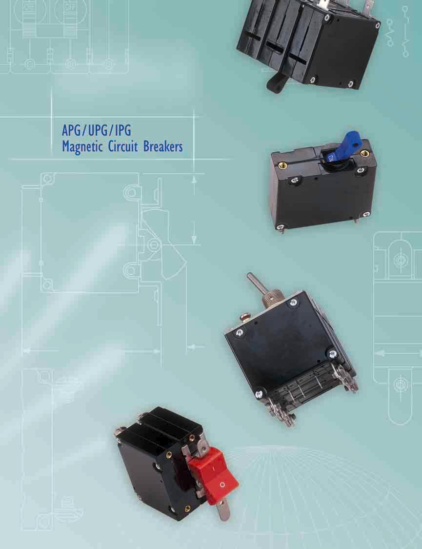
3 APG/ UPG SINGLE POLE CIRCUIT BREAKERS The APG/UPG magnetic circuit breaker provides low-cost power switching, reliable circuit protection and accurate circuit control in one complete package. It is intended for use in data processing and broadcast equipment, vending and amusement machines, military and marine applications, and wherever precision operation is required. Designed using a current sensitive hydraulic magnetic principle, the APG/UPG adapts itself to many applications and environments. Temperature compensations which affect fuses and other thermal devices are not a concern. Nuisance tripping is minimized. The APG/UPG is available in a wide variety of configurations with a choice of delays and ratings. In addition, it is available in either DC, 50/60Hz or 400Hz versions. Available in single or multi-pole variations, the APG/UPG comes with a variety of actuators. To enhance front-panel aesthetics, toggle or rocker actuated handles and caps are available in a variety of attractive colors. Multi-pole circuit breakers can be furnished with either single or multiple actuators. In addition, a unique sealed, single handle toggle version for harsh or military environments is available in single or multi-pole configurations. The UPG circuit breaker is recognized under UL Standard 077, file numbers E6640 and E It is also certified by CSA, file number LR The APG is qualified to MIL-PRF APG/UPG circuit breakers are available in one through four pole assemblies with a variety of pole arrangements, terminal styles, and accessories to meet your specifications, including APG/UPG adapter plate option to allow mounting in APL/UPL cutout. Single Pole,Toggle.590 DIA. [5.00] 2.00 [50.80].22 [3.00] X [4.66] APG/UPG 2.00 [50.80] APG/UPG [5.6].660 [42.6].050 [26.67] 2X.56 [3.96].75 [9.05].69 [7.53].66 [42.6].3 [3.30] 6 32 THD..87 [4.75] DEEP (TYP.) M3 S0. THD. OPTIONAL.68 [4.27] Single Pole, Mounting Detail 32º 32º Single Pole APG 6-* Terminals.53 [38.86] Amp Rating Push-on 8-32 M M5.23 [5.84] Adapter Plate** Notes: Tolerance ±.05 [.38] unless noted. Dimensions in Brackets [ ] are millimeters. * * Allows mounting in APL/UPL cutout. 30A > 30A X X X X X APG/UPG Single Pole Circuit Breakers 83

4 MULTI-POLE CIRCUIT BREAKERS Two Pole Breakers An assembly consisting of two single pole units, having their trip mechanisms internally coupled, and with a single toggle handle, forms the APG/UPG-. It is also possible to provide a handle per pole, which is referred to as UPGH. Individual poles may differ in ratings, delays and internal connections. An auxiliary switch may be included in either or both poles if they are of the series trip type. Screw-type terminals can be provided, in which case the designation would be APG/UPG-66. Two Pole.640 [4.66].69 [7.53] UPG.590 DIA. [5.00] UPGH 6 32 THD..87 [4.75] DEEP (TYP.) M3 S0. THD. OPTIONAL 32º 2.00 [50.80] 32º.22 [3.00].66 [42.6] APG/UPG 2.00 [50.80] APG/UPG [5.6].3 [3.30].55 [38.48] (Optional, handle may be in pole instead of pole 2).75 [9.05].55 [38.48].68 [4.27] UPG UPGH.56 [3.96] (2 PER POLE) [9.05].660 [42.6].050 [26.67] [9.05] ( PER POLE) Two Pole* Two Pole Panel Mounting Detail: Tolerance ±.005 [.3] unless noted. 84 Multi-Pole Circuit Breakers Note: Tolerance ±.05 [.38] unless noted. Dimensions in Brackets [ ] are millimeters. * See single pole mounting detail for hole sizes and locations.
5 Three Pole and Four Pole Breakers The three pole structure consists of three single pole units assembled with an internal mechanical interlock which actuates all units simultaneously. A single toggle handle operates all three poles, or a handle per pole is available. The four pole structure consists of four single pole units assembled with an internal mechanical interlock which actuates all units simultaneously. A double toggle handle operates all four poles, or a handle per pole is available. The individual poles need not have identical characteristics and any series trip pole may have an auxiliary switch. If screw-type terminals are required, the breaker designation will be APG/UPG- 666 for a three pole version and APG/UPG-6666 for a four pole version. Breaker poles are numbered consecutively when viewed from the terminal side, with the ON position up, starting with Pole # on the left side and proceeding to the right..640 [4.66] APGH/UPGH 2.00 [50.80] APGH/UPGH [5.6].69 [7.53].3 [3.30] 32º 32º Three Pole Three Pole [57.53] [9.05] [9.05] [57.53] UPG UPGH Mounting Detail [9.05] [9.05] Mounting Detail [9.05] [9.05] * See single pole mounting detail for hole sizes and locations. Three Pole* Three Pole* Four Pole Four Pole [9.05] 3.05 [76.58] APG/UPG only [9.05] [9.05] [9.05] 3.05 [76.58] APGH/UPGH only Mounting Detail [9.05] [9.05] [9.05] Mounting Detail [9.05] [9.05] [9.05] Four Pole* Four Pole* Multi-Pole Circuit Breakers 85
 M3 S0. THD. OPTIONAL.55 [38.48] 2.265 [57.53] 2.00 [50.80].53 [38.86].22 [3.00] 2.48 [63.02].66 [42.6] ON ON ON ON ON 2.59 [65.")
6 APGHX/ UPGHX BREAKERS APGHX / UPGHX Rocker actuated APGHX/UPGHX provides one rocker handle for each pole of a multi-pole circuit breaker. Number of Poles Dimension A 2 Pole 3 Pole.50 ±.005 [38.35±.3] 2.265±.005 [57.53±.3] Two Pole Three Pole.23 [5.84] 6 32 THD. (TYP.) M3 S0. THD. OPTIONAL.55 [38.48] [57.53] 2.00 [50.80].53 [38.86].22 [3.00] 2.48 [63.02].66 [42.6] ON ON ON ON ON 2.59 [65.79].340 [8.64].640 [4.66] APGX / UPGX [60.70].440 [.8].540 [3.72].75 [9.05] ± [8.67 ±.3] HANDLE WIDTH.75 [9.05].75 [9.05] APGX / UPGX [6.52] Panel Mounting Detail: Tolerance ±.005 [.3] unless noted. Two Pole.50 [38.35] Three Pole [57.53].660 [42.6].260 [32.00].660 [42.6].260 [32.00] 4X.56 [3.96] [9.05].200 [5.08] 6X.56 [3.96] [9.05] [9.05].200 [5.08] 86 APGHX / UPGHX Breakers
![APGX/ UPGX BREAKERS APGX / UPGX Rocker actuated APGX / UPGX provides one rocker handle per circuit breaker. Single Pole Two Pole.23 [5.84].75 [9.05] 6 32 THD. (TYP.) M3 SO. THD. OPTIONAL.55 [38.48] 2.](/docs-images/71/65627391/images/7-1.jpg "00 [50.80].53 [38.86].22 [3.00] 2.59 [65.79] 2.48 [63.02] ON.66 [42.6] ON.640 [4.66] APGX / UPGX 2.390 [60.70] APGX / UPGX 6 2.422 [6.52].440 [.8] ±.005.735 [8.67 ±.3] HANDLE WIDTH.540 [3.")
7 APGX/ UPGX BREAKERS APGX / UPGX Rocker actuated APGX / UPGX provides one rocker handle per circuit breaker. Single Pole Two Pole.23 [5.84].75 [9.05] 6 32 THD. (TYP.) M3 SO. THD. OPTIONAL.55 [38.48] 2.00 [50.80].53 [38.86].22 [3.00] 2.59 [65.79] 2.48 [63.02] ON.66 [42.6] ON.640 [4.66] APGX / UPGX [60.70] APGX / UPGX [6.52].440 [.8] ± [8.67 ±.3] HANDLE WIDTH.540 [3.72] (Optional, handle may be in pole 2 instead of pole ) Three Pole One,Two & Three Pole [57.53] [9.05] ON.660 [42.6].260 [32.00] 2X.56 [3.96].200 [5.08] Panel Mounting Detail: Tolerance ±.005 [.3] unless noted. Note: Tolerance ±.05 [.38] unless noted. Dimensions in Brackets [ ] are millimeters. APGX / UPGX Breakers 87
8 APGN/ UPGN BREAKERS Bat Handle / Panel Seal (APGN / UPGN) The APGN is designated to provide circuit protection in harsh and military environments. Waterproof panel integrity is provided by an O ring bushing seal and silicon rubber gland within the bushing/handle assembly. Single, two or three pole versions are available with two and three pole versions featuring a single operating handle and mounting bushing..530 [38.86].230 [5.84].625 [5.88].30 [3.30] ±.03 ± ON 6 32 MTG. SCREW 3º ±3º APGN [55.88] APGN [56.69] 3º ±3º 32 HEX NUT LOCKWASHER RUBBER O RING Single Pole Two Pole Three Pole KEYWAY.060 [.52].065 [.65] WIDE.030 [.76].035 [.89] DEEP.220 [3.00].656 [6.66] [50.80] [9.05].55 [38.48] (Optional handle may be in pole 2 instead of pole ) [57.53] Single Pole Two Pole* Three Pole*.56 [3.96] [9.05] [9.05] [9.05].55 [3.08].656 [6.66] Panel Mounting Detail: Mounting detail tolerance ±.005 [.3] unless noted. Optional Handle *See single pole mounting detail for hole sizes and locations. 88 APGN/UPGN Breakers
9 APG/ UPG HANDLES AND ACTUATORS Standard Handle Location (Applies to 2 Pole Only) Toggle Handles Toggle Handles The APG/UPG circuit breaker is available with toggle handles in six different colors. For attractive panel appearance, color caps are also available. Handles may be specified in black, white, yellow, red, blue and green. For multi-pole units, specify handle per unit or handle per pole. APG/UPG Color Caps For attractive panel appearance the following color caps are available for use on APG/UPG breakers. Bat Handle/ Panel Seal APGN/UPGN Color Caps Order Separately Red Green White Gray Rocker Blue Yellow ON Orange Brown Black APGX/UPGX Note: Tolerance ±.05 [.38] unless noted. Dimensions in Brackets [ ] are millimeters. APG/UPG Handles and Actuators 89
10 IPG MAGNETIC CIRCUIT BREAKERS The IPG circuit breakers provide the advantages of magnetic stand alone protection and compliance with UL, CSA, SEV, VDE and IEC standards. They are UL Recognized, CSA Certified, VDE approved and CE compliant to VDE 0642 (EN60934). Additionally, they conform to the spacing requirements of VDE 0730, 0804, 0805 and 0806, and IEC 950 for use in office machines and data processing equipment. IPG circuit breakers have current ratings from.020 to 50 amperes, 250Vac, 65Vdc, and an auxiliary switch is available with either gold or silver contacts. They feature one through four pole configurations, with one handle per pole. A choice of handle actuation colors, terminals and hardware are available and international markings are standard. And, with an adapter plate, they will fit in panels cut for Airpax APL and UPL type breakers..640 [4.66] [5.6] Single Pole.590 [5.00] [50.80].220 [30.99] [9.05].690 [7.53] 32º 32º.250 [6.35] 6 32 THREAD.40 [3.56] DEEP (TYP.) M3 ISO THD. OPTIONAL.660 [42.6].68 [4.27] Two Pole [9.05].55 [38.48] Note: Main terminals are stationary male push-on type.250 [6.35] wide x.03 [.787] thick x.32 [7.92] long or 8-32 x.87 [4.75] screw type ( 30A) x.87 [4.75] screw type (>30A). Three Pole [9.05] [9.05] [57.53] Four Pole [9.05] [9.05] 3.05 [76.58] [9.05].56 [3.96] (2 PER POLE) Panel mounting detail: Tolerance ±.005 [.3] unless noted..660 [42.6].050 [26.67] [9.05] ( PER POLE) 90 IPG Magnetic Circuit Breakers
![APG/UPG/IPG CONFIGURATIONS Series and Switch Only.53 [38.86].23 [5.](/docs-images/71/65627391/images/11-0.jpg "84].53 [38.86].23 [5.84] Series Trip The most popular configuration for magnetic protectors is the series trip where the sensing coil and contacts are in series with the load being protected.")
11 APG/UPG/IPG CONFIGURATIONS Series and Switch Only.53 [38.86].23 [5.84].53 [38.86].23 [5.84] Series Trip The most popular configuration for magnetic protectors is the series trip where the sensing coil and contacts are in series with the load being protected. The handle position conveniently indicates circuit status. In addition to providing conventional overcurrent protection, it s simultaneously used as an on-off switch. Series Switch Only Shunt and Dual Coil.53 [38.86].38 [35.05].23 [5.84] Shunt Dual Coil Shunt Trip The shunt trip is designed for controlling two separate loads with one assembly. The control is established by providing overload protection for the critical load. When the current through this load becomes excessive and reaches the trip point, the protector will open and remove power from both loads simultaneously. The total current rating of both loads must not exceed the maximum contact rating. Tapped Coil.23 [5.84].53 [38.86].38 [35.05] 30º Tapped Coil Note: Tolerance ±.05 [.38] unless noted. Dimensions in Brackets [ ] are millimeters. APG/UPG/IPG Configurations 9
12 APG/ UPG/ IPG CONFIGURATIONS (CONT D) Relay Trip This permits the overload sensing coil to be placed in a circuit which is electrically isolated from the trip contacts. The coil may be actuated by sensors monitoring pressure, flow, temperature, speed, etc. Other typical applications include crowbar, interlock and emergency/rapid shutdown circuitry. Trip may be accomplished by voltage or current, which must be removed after trip. Relay and Dual Coil.38 [35.05].6 [5.50].53 [38.86].23 [5.84] Relay Dual Coil.6 [5.50].23 [5.84] Relay and Four Terminal Dual Coil with Screw Terminal.38 [35.05].53 [38.86] 30º (TYP.) Auxiliary Switch This is furnished as an integral part of a series pole in single or multi-pole assemblies. Isolated electrically from the protector s circuit, the switch works in unison with the power contacts and provides indication at a remote location of the protector s on-off status. Voltage Trip Sometimes called dump circuits or panic trip circuits, these units make it possible to open main power contacts with lower power inputs from one or more sources. This configuration is becoming increasingly more important for sensitive circuitry and denser packaging in automation systems. Available in series, shunt, or relay configurations. Auxiliary Switch.295 [7.49].0 [2.79] - REC 4 - REG 4 Quick Connect Terminals.32 [7.92].87 [4.75] - REC 5 - REG 5 Quick Connect Terminals Series with Auxiliary Switch All auxiliary switch terminals.020[.5] thick Standard auxiliary switch is REC 4. C NO NC Breaker in position Note: Main terminals are stationary male push-on type.250 [6.35] wide, x.03 [.787] thick, x.32 [7.92] long or 8-32 x [4.75] screw type ( 30A), 0-32 x.87 [4.75] screw type (>30A). 92 APG/UPG/IPG Configurations Note: Tolerance ±.05 [.38] unless noted. Dimensions in Brackets [ ] are millimeters.
13 APG/ UPG/ IPG OPERATING CHARACTERISTICS Nominal DCR and Impedance DC Delays 50/60Hz Delays 400Hz Delays Current Ratings in Amperes Resistance in Ohms Dual Coil Impedance in Ohms Dual Coil 6-62 Impedance in Ohms Notes: DCR and impedance based on 00% rated current applied and stablized a minimum of one hour. Tolerance:.02 amperes to 2.5 amperes, ± 20%; 2.6 amperes to 20 amperes, ± 25%; 2 amperes to 50 amperes, ± 50%. Consult factory for special values and for coil impedance of delays not shown. Percentage Overload vs.trip Time in Seconds Delay 00% 25% (Note A) 50% 200% 400% 600% 800% 000% 40 May Trip.040 Max..035 Max..030 Max..025 Max..020 Max..08 Max. 4 May Trip May Trip Max..00 Max..032 Max..020 Max..020 Max..020 Max..020 Max. 43 & 400 May Trip May Trip.032 Max..024 Max..020 Max..08 Max..06 Max..05 Max Max..070 Max.032 Max..020 Max..020 Max..020 Max..020 Max. 53 & May Trip.040 Max..035 Max..030 Max..025 Max..020 Max..08 Max Max..00 Max..050 Max..022 Max..07 Max..07 Max..07 Max Notes: All trip curves and trip currents are specified with the breaker mounted in the normal vertical position at ambient temperture of +25 C. Breakers do not carry current prior to application of overload. A: Ratings above 30 amps may deviate from the above limits by approximately 0% (30% for delay 49). For dual frequency curves, see page 94. APG/UPG/IPG Operating Characteristics 93

14 APG/ UPG/ IPG OPERATING CHARACTERISTICS AND DELAY CURVES Dual Frequency (DC/60Hz) Delay 00% 35% 50% 200% 400% 600% 800% 000% Notes: All trip curves and trip currents are specified with the breaker mounted in the normal vertical position at ambient temperture of +25 C. Breakers do not carry current prior to application of overload. Inrush Pulse Tolerance It can be seen that the 64, 65 and 66 delays have a high inrush capability and for most applications an inertia wheel would not be required. Pulse tolerance is defined as a single pulse of half sine wave peak current amplitude of 8 milliseconds duration that will not trip the circuit breaker DELAY 60 Delay Pulse Tolerance 00 6, 62 0 times rated current 6F, 62F 20 times rated current 64, 65, times rated current 64F, 65F, 66F 35 times rated current Note: These limits do not apply to dual coil and tapped coil units MAY TRIP /60Hz Delay Curves (typ) A choice of delays is offered for DC, 50/60Hz, and 400 Hz applications. Delays 40, 50, 60, 49, 59 and 69 provide fast-acting, instantaneous trip and are often used to protect sensitive electronic equipment (not recommended where known inrush exists). Delays 4, 5, 6 and 7 have a short delay for general purpose applications. Delays 42, 52 and 62 are long enough to start certain types of motors and most transformer and capacitor loads. Delays 43, 53 and 63 are long delays for special motor applications at 400Hz DC and 50/60Hz MAY TRIP DELAY Operating Characteristics & Delay Curves

15 APG/UPG/IPG DELAY CURVES 50/60Hz Delay Curves (typ) MAY TRIP DELAY DELAY DELAY MAY TRIP MAY TRIP DELAY MAY TRIP MAY TRIP DELAY Delay Curves 95
16 APG/UPG/IPG DELAY CURVES DC Delay Curves (typ) DELAY MAY TRIP DELAY MAY TRIP DELAY DELAY MAY TRIP MAY TRIP DELAY MAY TRIP Delay Curves
17 APG/UPG/IPG DELAY CURVES 400Hz Delay Curves (typ) DELAY DELAY MAY TRIP MAY TRIP DELAY MAY TRIP DELAY DELAY MAY TRIP MAY TRIP Delay Curves 97
18 SPECIFICATIONS Trip Free Will trip open on overload, even when forcibly held in the ON position. Trip Indication The operating handle moves positively to the position on overload. Ambient Operation APG/UPG breakers operate normally in temperatures between -40 C and +85 C. Insulation Resistance Not less than 00 megohms at 500Vdc. Dielectric Strength APG/UPG/IPG breakers withstand 500 volts, 60Hz for 60 seconds between all electrically isolated terminals. Except auxiliary switch terminals shall withstand 600 Volts at 60Hz. Endurance Withstands 0,000 operations at rated voltage and current or withstands 50 operations of 600% AC or 000% DC rated current at rated voltage followed by 6000 operations at rated voltage and current, in accordance with UL 077. Auxiliary Switch Rating 0 250Vac 3 50Vdc Agency Approvals Voltage (V) Rated Current (A) Minimum/Maximum Interrupting Capacity (A) Maximum Rating (V) Frequency (Hz) Phase Minimum Poles UL/CSA UL077/CSA Maximum Series Fuse 32 DC none 65 DC none 30 DC none 20 50/ /240 50/ none /60 & /60 & none /60 & / / none & & none & Note: Series fuse to be a branch-circuit UL approved type K-5 back-up fuse rated at not more than four times the rating of the highest-rated type UPG (5 amperes minimum). 98 Specifications
19 SPECIFICATIONS Moisture Resistance Meets all the requirements of MIL-PRF when tested in accordance with Method 06 of MIL-Std Approximate Weight Per Pole Ounces Grams Salt Spray (Corrosion) Meets requirements of MIL-PRF when tested in accordance with Method 0 of MIL-Std All APG/UPG breakers are constructed with stainless steel springs and plated parts. In addition to meeting normal requirements for moisture and salt spray resistance, the breaker meets the fungus resistance requirements of MIL-PRF Poles One through four poles with the UPGH, one through three poles with all other types. MIL-PRF (APG) Single, two and three pole versions, with and without the auxiliary switch option, have been qualified to MIL-PRF Construction Series, shunt, relay, dual coil, tapped coil, voltage trip, no-voltage trip, auxiliary switch, switch only. Various delays and combinations. APG/UPG/IPG APGN/UPGN Recommended Torque Specifications 6-32 mounting inserts 6-8 inch pounds M3 mounting inserts 4-5 inch pounds 8-32 screw terminals 0-2 inch pounds M4 screw terminals 0-2 inch pounds 0-32 screw terminals 4-5 inch pounds M5 screw terminals 4-5 inch pounds 2-32 mounting bushing inch pounds Shock Withstands 00G or more without tripping while carrying full rated current per MIL-Std. 202, Method 23, Test Condition I. Instant trip breakers are tested at 80% of rated current. Vibration Withstands 0G without tripping while carrying full rated current per MIL-Std. 202, Method 204, Test Condition A. Instant trip breakers are tested at 80% of rated current. Specifications 99
20 APG/ UPG DECISION TABLES How to Order The ordering code for APG/UPG circuit breakers may be determined by following the steps in the decision tables shown here. The coding given permits a self-assigning part number but with certain limitations. Units with mixed ratings, combinations of styles, or constructions not listed in the third decision table, require a factory-assigned part number. With these, it is suggested that order entry be by description and/or drawings, and a part number will be established. Additionally, it is standard policy to establish a factory-assigned part number whenever a descriptive drawing exists to provide cross reference, traceability and manufacturing control. When specifying a circuit breaker for AC motor start or high inrush applications, the peak amplitude and surge duration should be specified for factory assistance in rating selection. For example, the following is the code for a single pole UPG, quick-connect type terminal series unit with auxiliary switch, designed for operation in a 50/60Hz circuit. It has a short time delay and a rating of 20 amperes. A white handle is specified by the seventh decision table. To determine the ordering number for your particular APG/UPG unit, simply follow the steps shown. You may use this number to place an order or as a reference for further questions you may have. Type APG UPG APGX UPGX APGN UPGN APGH UPGH First Decision Type APGHX UPGHX Description One handle per unit One handle per unit UL Recognized and CSA Certified One rocker handle per unit One rocker handle per unit UL Recognized and CSA Certified Panel seal (one bat handle per unit) Panel seal (one bat handle per unit) UL Recognized and CSA Certified One handle per pole One handle per pole UL Recognized and CSA Certified One rocker handle per pole One rocker handle per pole UL Recognized and CSA Certified Notes: A It is recommended that power leads be soldered to breakers having quick-connect terminals for current trip ratings above 0 amperes. B The standard current values for 00% of rated current are listed. Please consult an Airpax office or sales representative for other values. C UL recognized and CSA certified applications above 30 amperes are restricted to loads having a power factor of 75 minimum and limited to 32Vdc only. Standard terminals on ratings over 30 amperes are 0-32 screw type. D Four pole breakers are available only in the APGH/UPGH and APG/UPG types. The APGH/ UPGH four pole provides one handle per pole, while the APG/UPG four pole has handles in the center two poles only, for simplified mounting. E Sub panel mount available in APGX/UPGX configuration only. F When A is specified in the sixth decision in conjunction with APG/UPG-6 type, metric screw terminals are supplied. G If a circuit breaker is marked in this manner, it means 277V per pole single phase source. Thus, if a two or three pole unit is marked 277V, all line terminals must be connected to the same phase, assuming the 277V is taken from line to neutral of 3 phase 277/480V system. 2 Second Decision Poles (Note A) Quick- Connect Terminals Screw Terminals Number of poles Single pole unit Two pole unit Three pole unit Four pole unit (Note D) 00 APG/UPG Decision Tables
21 3 Third Decision 4 Fourth Decision Internal Configuration Hz and Delay REC4 Switch only (omit 4th and 5th decisions) Series Auxiliary switch*.0 quick-connect * 400Hz 50% instant trip 400Hz short delay 400Hz long delay 400Hz motor start -REG4 -REC5 Auxiliary switch* (Gold Contacts).0 quick-connect Auxiliary switch*.87 quick-connect Hz 30% instant trip DC 50% instant trip DC short delay -3 Shunt (up to 30 amperes only) -52 DC long delay -4 Relay (up to 30 amperes only) -53* DC motor start *Only one auxiliary switch is normally supplied on two and three pole units. Can be used for solder terminals also. Switch is located in the right-hand pole (viewed from terminal end) unless otherwise specified. Multi-pole units with mixed construction, poles numbered left to right when viewed from terminal end DC 25% instant trip 50/60Hz 50% instant trip 50/60Hz short delay 50/60Hz long delay -600* 50/60Hz motor start delay 7 Seventh Decision Example: UPG -REC * /60Hz, short delay (high pulse) 50/60Hz, long delay (high pulse) 50/60Hz, motor start (high pulse) 50/60Hz 25% instant trip DC, 50/60Hz short delay DC, 50/60Hz long delay -73* DC, 50/60Hz motor start delay For addition of inertial delay, add an F to any delay number. * Not available above 30 amperes Handle/Actuator Color** Toggle Handle Color Black w/ white markings Yellow w/ black markings Red w/ white markings Blue w/ white warkings Green w/ white markings White w/ black markings Rocker/Actuator Color Black w/o markings -0 Black w/ white markings 5 Fifth Decision -02 Red w/o markings Nominal Average Rating (Note B) -05 Opaque white w/o markings Current Code Ratings (Amps) Current Code Ratings (Amps) * 40.0* 50.0* 6 -A -B Sixth Decision Optional Metric thread mounting (Not available on APGN/UPGN) (Note F) Sub panel mount (Note E) Gray w/o markings Translucent white w/o markings Red w/ white markings Opaque white w/ black markings Gray w/ black markings Translucent white w/ black markings **Not available for bat handle. Unmarked handles are available. Please consult factory See page 8 for maximum voltage ratings. (*Note C) -C -H 277Vac 50/60Hz (Note G) International handle markings Standard current ratings listed. For other ratings, please consult factory. One or more descriptions may be used as required. If this table is not used, go directly to the seventh decision. APG/UPG Decision Tables 0

22 IPG DECISION TABLES How to Order The ordering code for IPG circuit breakers may be determined by following the steps in the decision tables shown here. The coding given permits a self-assigning part number but with certain limitations. Units with mixed ratings, combinations of styles, or constructions not listed in the third decision table, require a factory-assigned part number. With these, it is suggested that order entry be by description and/or drawings, and a part number will be established. Additionally, it is standard policy to establish a factory-assigned part number whenever a descriptive drawing exists to provide cross reference, traceability and manufacturing control. When specifying a circuit breaker for AC motor start or high inrush applications, the peak amplitude and surge duration should be specified for factory assistance in rating selection. For example, the following is the code for a single pole IPG, quick-connect type terminal series unit with auxiliary switch, designed for operation in a 50/60Hz circuit. It has a short time delay and a rating of 20 amperes. Metric mounting inserts and a white handle are also specified. To determine the ordering number for your particular IPG unit, simply follow the steps shown. You may use this number to place an order or as a reference for further questions you may have. Notes: A It is recommended that power leads be soldered to breakers having push-on terminals for current trip ratings above 0 amperes. B The standard current values for 00% of rated current are listed in the fifth decision table. Please consult an Airpax office or sales representative for other values. C All IPG breakers meet normal requirements for moisture and salt spray resistance. D UL recognized and CSA certified applications above 30 amperes are restricted to loads having a power factor of.75 minimum, and limited to 32Vdc only. VDE approval above 30 amperes is restricted to 32Vdc and 20Vac 50/60Hz. Standard terminals on ratings over 30 amperes are 0-32 screw type. E When A is specified in the sixth decision in conjunction with IPG-6 type, metric screw terminals are supplied. Type IPG IPGH 2 First Decision Type Description Single pole with one handle per unit (Not available in multi-pole configuration) Multi-pole with handle per pole Second Decision Poles Push-On Terminals Screw Terminals Third Decision Internal Configuration -REC4 -REG4 -REC5-3 Number of poles Single pole Two pole Three pole Four pole Std. Handle Color Black Black Switch only (omit 4th and 5th decisions) Series Auxiliary switch*.0 quick-connect Auxiliary switch* (Gold Contacts).0 quick-connect Auxiliary switch*.87 quick-connect Shunt (up to 30 amperes only) *Only one auxiliary switch is normally supplied on two and three pole units. Switch is located in the right-hand pole (viewed from terminal end) unless otherwise specified. 02 IPG Decision Tables
23 4 Fourth Decision 5 Fifth Decision Hz and Delay Nominal Amperage Rating * * * 400Hz 50% instant trip 400Hz short delay 400Hz long delay 400Hz motor start 400Hz 30% instant trip DC 50% instant delay DC short delay DC long delay DC motor start DC 25% instant trip 50/60Hz 50% instant trip 50/60Hz short delay 50/60Hz long delay, 50/60Hz, short delay (high pulse) 50/60Hz, long delay (high pulse) 50/60Hz, motor start (high pulse) Current Code Ratings (Amps) Current Code (*Note D) Standard current ratings listed. For other ratings, please consult factory. Ratings (Amps) * 40.0* 50.0* -69 * Not available above 30 amperes. number. 6 Sixth Decision Optional Example: IPG - REC V -A Metric thread mounting (Note E) When this table is not used, table 7 may be substituted and U.S. thread will be supplied V 7 Seventh Decision IPG and IPGH V = VDE Approved The shaded areas denote VDE approval options. This approval requires the addition of a V at the end of the part number. The V will be added to any part number formed entirely from shaded decisions. If non-shaded areas are selected, the unit will not be VDE approved, but other approvals still apply Toggle Handle Color Black Yellow Red Blue Green White IPG Decision Tables 03
APG/UPG/IPG Series Existing Designs Only APG/UPG/IPG
 APG/UPG/IPG Series Existing Designs Only APG/UPG/IPG APG/UPG/IPG Series Hydraulic Magnetic Circuit Protectors INTRODUCTION IMPORTANT NOTICE: The APG/UPG is a legacy product and no new design-in orders
APL/UPL, 205/295 Series Magnetic Circuit Protectors
 APL/UPL, 205/295 APL/UPL, 205/295 Series Magnetic Circuit Protectors Introduction 68 Single & Multi-Pole 69 Barriers 7 Configurations 72 Operating Characteristics 74 Delay Curves 75 Specifications 80 Decision
Magnetic Circuit Protectors 153. Multi-Pole Circuit Protectors 154. APL/UPL, 205/295 Barriers 155. Configurations 156. Operating Characteristics 158
 Magnetic Circuit Protectors 53 Multi-Pole Circuit Protectors 54 APL/UPL, 205/295 Barriers 55 Configurations 56 Operating Characteristics 58 Delay Curves 59 Specifications 64 APL/UPL Decision Tables 70
IELR Rail-Mount Series Magnetic Circuit Protectors
 IELR Rail-Mount IELR Rail-Mount Series Magnetic Circuit Protectors Introduction 92 Single Pole 93 Specifications 94 Operating Characteristics 95 Delay Curves 96 Approvals & Decision Tables 200 IELR Series
IELR Series
 IELR Series Rail-Mount Magnetic Circuit Protectors Introduction Poles Specifications Operating Characteristics Delay Curves Approvals Decision Tables 6 62 63 64 65 69 70 IELR Series Rail-Mount Hydraulic
209/219/229 Multi-Pole Circuit Protectors 202 branch circuit applications such as EDP, air conditioners, panel boards
 The 29, E-Frame circuit breaker combines power switching with accurate, reliable circuit protection 29/29/229 Magnetic Circuit Protectors 99 in a compact single or multipole 249 Power Selector Breaker
Ihr autorisierter Distributor: Neumüller Elektronik GmbH
 IELR Series Rail-Mount Magnetic Circuit Protectors Introduction Poles Specifications Operating Characteristics Delay Curves Approvals Decision Tables 6 62 63 64 65 69 70 Neumüller Elektronik GmbH Gewerbegebiet
IELR Rail-Mount Series Magnetic Circuit Protectors
 Series Magnetic Circuit Protectors Introduction 53 Single Pole 54 Specifications 55 Operating Characteristics 56 Delay Curves 57 Approvals & Decision Tables 6 IELR Series Hydraulic Magnetic Circuit Protectors
209/219/229/249/279 SERIES HYDRAULIC MAGNETIC CIRCUIT PROTECTORS
 209/219/229/249/279 SERIES HYDRAULIC MAGNETIC CIRCUIT PROTECTORS Introduction The 209, E-Frame circuit breaker combines power switching with accurate, reliable circuit protection in a compact single or
Products :: Circuit Protection :: Hydraulic/Magnetic Circuit Breakers
 Products :: Circuit Protection :: Hydraulic/Magnetic Circuit Breakers Hydraulic/Magnetic Circuit Breaker B-Series B-Series PDF elibrary The B-Series hydraulic/magnetic circuit breakers are compact and
PERCENT OF RATED CURRENT
 A-D Series Time Delay Values PERCENT OF RATED CURRENT NOTES: UL489 C-Series Breakers available with Delay Curves 11, 12, 14, 16, 21, 22, 24, 26, 42, 44, 46. Delay Curves 11,12,14,16,21,22,24,26,42,44,46,52,54,56:
Time Delay Values (E-Series)
") Time Delay Values (ESeries) AC Instantaneous 00 0 INSTANTANEOUS CURVE NO. 20 00 0 DC D.C. INSTANTANEOUS CURVE NO. 0 0. 0..0.0.00 200 300 400 500 700 800 900 0 200.00 200 300 400 500 700 800 900 0 200 Short
Time Delay Values (ESeries) AC Instantaneous 00 0 INSTANTANEOUS CURVE NO. 20 00 0 DC D.C. INSTANTANEOUS CURVE NO. 0 0. 0..0.0.00 200 300 400 500 700 800 900 0 200.00 200 300 400 500 700 800 900 0 200 Short
Products :: Circuit Protection :: Hydraulic/Magnetic Circuit Breakers
 Products :: Circuit Protection :: Hydraulic/Magnetic Circuit Breakers Miniature Hydraulic/Magnetic Circuit Breaker M-Series M-Series PDF elibrary The M-Series miniature hydraulic/magnetic circuit breakers
E-Series General Specifications
 -Series General Specifications Ideally suited for higher amperage applications. Available with front and back mounting, screw terminals, stud terminals and heavy duty box wire connectors for solid wire
C-Series. Circuit Breaker
 C-Series Circuit Breaker The C-Series hydraulic/magnetic circuit breakers are ideal for applications that require higher amperage and voltage handling capability in a smaller package. They are available
C-Series. Circuit Breaker
 C-Series Circuit Breaker The C-Series hydraulic/magnetic circuit breakers are ideal for applications that require higher amperage and voltage handling capability in a smaller package. They are available
IAR/IUR/IER/CUR/CER Series 1RU Magnetic Circuit Protectors
 IAR/IUR/IER/CUR/CER Series RU Magnetic Circuit Protectors IAR/IUR/IER/CUR/CER [RU] Introduction 49 Poles & Terminals 50 Configurations 53 Delay Curves & Specs 54 Operating Characteristics 55 Hardware 56
D-Series. Circuit Breaker
 D-Series Circuit Breaker Designed for snap-on-back panel rail mounting on either a 35mm x 7.5mm, or a 35mm x 15mm Symmetrical Din Rail, allowing rapid and simple mounting and removal of the breaker. It
Magnetic and Hydraulic-Magnetic Circuit Breaker 8340-F...
 Magnetic and Hydraulic-Magnetic Circuit Breaker 830-F... Description Single and multipole magnetic circuit breakers with trip-free mechanism and toggle actuation. A choice of fast magnetic only or hydraulically
Magnetic and Hydraulic-Magnetic Circuit Breaker 8340-F...
 Description Single and multipole magnetic circuit breakers with trip-free mechanism and toggle actuation. A choice of fast magnetic only or hydraulically delayed switching characteristics (S-type MO or
IAG/IUG/IEG/CEG/LEG Single Pole Circuit Protectors 91. IAG/IUG/IEG/CEG/LEG Multi-Pole Circuit Protectors 92
 Single Pole Circuit Protectors 9 Multi-Pole Circuit Protectors 92 IAGH/IUGH/IEGH/CEGH/LEGH Circuit Protectors 93 IAGX/IUGX/IEGX/CEGX/ IAGZX/IUGZX/IEGZX/ CEGZX/LEGZX Rocker Circuit Protectors 94 IAGBX/IUGBX/IEGBX/CEGBX/LEGBX
E-Series General Specifications
 -Series General Specifications Ideally suited for higher amperage applications. Available with front and back mounting, screw terminals, stud terminals and heavy duty box wire connectors for solid wire
D-Series CIRCUIT BREAKER
 D-Series CIRCUIT BREAKER Designed for snap-on-back panel rail mounting on either a 35mm x 7.5mm, or a 35mm x 15mm Symmetrical Din Rail, allowing rapid and simple mounting and removal of the breaker. It
W69-X2Q12-20 Product Details
 TE Connectivity My Cart My Part Lists Sign In/Register English (Change) Have a Question? Chat with a Product Information Specialist What can we help you find? Products Industries Resources bout TE My ccount
Magnetic and Hydraulic-Magnetic Circuit Breaker
 Description Single or multipole hydraulic-magnetic circuit breakers with trip-free - mechanism and toggle actuation. A choice of switching characteristics ensures suitability for a wide range of applications.
IAG/IUG/IEG/CEG/LEG Series
 IAG/IUG/IEG/CEG/LEG Series Magnetic Circuit Protectors Introduction Poles Handles Configurations perating Characteristics Delay Curves Specifications Decision Tables 99 00 03 08 0 5 7 IAG/IUG/IEG/CEG/LEG
PERFORMANCE SPECIFICATION
 INCH-POUND MIL-PRF-6106/13F 17 November 2011 SUPERSEDING MIL-PRF-6106/13E 10 November 2000 PERFORMANCE SPECIFICATION RELAY, ELECTROMAGNETIC, 25 AMPERE, 3PST, NO, WITH 2 AMPERE 1PDT AUXILIARY CONTACTS,
MULTI 9 System Catalog UL Recognized C60N Supplementary Protectors
 UL Recognized C60N Supplementary Protectors B Curve C60N Supplementary Protectors 1 MG24110 MG24125 MG24140 MG24155 15 MG17406 MG17436 MG17461 1.2 MG17402 MG17432 16 MG24118 MG24133 MG24148 MG24163 1.5
MULTI 9 System Catalog UL Recognized NC100H Supplementary Protectors
 B Curve NC100H Supplementary Protectors Rating 1P 2P 3P 4P 80 MG27164 MG27175 MG27186 MG27197 MULTI 9 System Catalog UL Recognized NC100H Supplementary Protectors C Curve NC100H Supplementary Protectors
W91-X Product Details
 TE Connectivity My Cart My Part Lists Sign In/Register English (Change) Have a Question? Chat with a Product Information Specialist What can we help you find? Products Industries Resources bout TE My ccount
Sensing and Control the Interactive Catalog.
 Interactive Catalog Supplements Catalog PDFs If you need detailed product information, or help choosing the right product for your application, see our Interactive Catalog Use the Interactive Catalog to
WMS SUPPLEMENTARY PROTECTORS
 WMS Supplementary Protectors Overview WMS SUPPLEMENTARY PROTECTORS Product Specification The WMS Supplementary Protector is a dual-rated product for both AC and DC supplies, in accordance with UL 1077
PERCENT OF RATED CURRENT
 A-D Series Time Delay Values PERENT OF RATED URRENT NOTES: UL489 -Series Breakers available with Delay urves 11, 12, 14, 16, 21, 22, 24, 26, 42, 44, 46. Delay urves 11,12,14,16,21,22,24,26,42,44,46,52,54,56:
D2SW-3L1HS D2SW-01L1HS
 Sealed Snap Action Switch D2SW Watertight Miniature Snap Action Switch High-quality watertight miniature Snap Action switch. Switch Body meets IP67 (IEC 529) requirements Monoblock construction assures
FAZ Supplementary Protectors, FAZ Miniature Circuit Breakers, P2 Disconnect Switches Overview
 FAZ Supplementary Protectors, FAZ Miniature Circuit Breakers, P2 Disconnect Switches Overview Supplementary Protectors / Miniature Circuit Breakers Page System overview 10/003 10/001 Supplementary protectors
UL 489 DIN rail branch circuit breakers
 UL 9 DI rail branch circuit breakers FAZ-A circuit breakers Product Overview UL 9 DI rail branch circuit breakers FAZ-A circuit breakers PRODUCT OVERVIEW Optimum and efficient protection Optimum product
9926 Series Branch Rated Circuit Breakers AC Version
 Branch Rated AC Version Hydraulic Magnetic Single pole and double pole versions 20/240 VAC, 50/60 Hz Up to 25A Just 3 mm wide Mounts on 35mm DIN-rail UL 489 listed, CSA C22.2 No. 5-02, CE VDE Ordering
TeSys IEC Contactors and Overload Relays
 TeSys IEC Contactors and Overload Relays Making High-Fault Short-Circuit Current Ratings Simple Schneider Electric is an industry leader in IEC contactors and overload relays, and is recognized as the
Model Number Structure
 Solid State Relays with Failure Detection Function G3PC CSM_G3PC_DS_E_1_1 Refer to Safety Precautions for All Solid State Relays. Detects failures in SSR used for heater temperature control and simultaneously
M-Series. Circuit Breaker
 M-Series Circuit Breaker The M-Series is a low cost, miniature hydraulic/magnetic circuit breakers ideally designed for demanding applications requiring space saving features, aesthetics and snap-in front
PERFORMANCE SPECIFICATION SHEET
 INCH-POUND MIL-PRF-39016/23F 15 June 2005 SUPERSEDING MIL-PRF-39016/23E 20 July 1988 PERFORMANCE SPECIFICATION SHEET RELAYS, ELECTROMAGNETIC, ESTABLISHED RELIABILITY, SPDT, LOW LEVEL TO 1.0 AMPERE WITH
Introduction Circuit Protection
 Introduction Circuit Protection Weidmuller s DIN-rail mounted circuit breakers are available for use in applications where circuit protection must be able to distinguish between circuit overloads and short
Type CBW58 Thermal Circuit Breaker Push to Reset Standard Profile
 Specifications: Amperage Range: 3A - 50A Voltage: 125 / 250 VAC, 50 VDC Frequency: 50-60 Hz Dielectric Strength: 1,500 VAC / 1 Minute Interrupting Rating: 3-50A 1000A @ 125/250VAC 3-30A 400A @ 125/250
PERFORMANCE SPECIFICATION SHEET SWITCHES, PUSH, 2 CIRCUIT AND DPDT, ALTERNATE AND MOMENTARY ACTION, 2 AMPERES, SPLASHPROOF
 INCH-POUND MIL-PRF-8805/99H 6 March 2008 SUPERSEDING MIL-PRF-8805/99H w/amendment 1 14 January 2004 PERFORMANCE SPECIFICATION SHEET SWITCHES, PUSH, 2 CIRCUIT AND DPDT, ALTERNATE AND MOMENTARY ACTION, 2
D2D. Door Interlock Switch. Ordering Information. Power Switch with Minimum Contact Gap of 3 mm. Model Number Legend.
 Door Interlock Switch Power Switch with Minimum Contact Gap of 3 mm Offers the minimum contact gap of 3 mm required for power switches as standard equipment. Highly reliable design conforms to European
1492-SP Supplementary Protectors
 Dual terminals provide wiring/bus bar flexibility and clamp from both sides to improve connection reliability Approval marks are easily visible on dome Terminal design helps prevent wiring misses Scratch-
PERFORMANCE SPECIFICATION SHEET
 PERFORMANCE SPECIFICATION SHEET INCH-POUND w/amendment 1 22 September 2005 SUPERSEDING MIL-PRF-39016/19G 1 April 2005 RELAYS, ELECTROMAGNETIC, ESTABLISHED RELIABILITY, DPDT, LOW LEVEL TO 1 AMPERE WITH
Type CBW57 Thermal Circuit Breaker Push to Reset Low Profile
 Specifications: Push to Reset - Low Profile Amperage Range: 3A - 30A Voltage: 125 / 250 VAC, 32 VDC Frequency: 50-60 Hz Dielectric Strength: 1500 VAC / 1 Minute Interrupt Rating: 3-30A 1000A @ 125/250
PERFORMANCE SPECIFICATION SHEET
 INCH-POUND MIL-PRF-39016/41E 15 June 2005 SUPERSEDING MIL-PRF-39016/41D 20 July 1988 PERFORMANCE SPECIFICATION SHEET RELAYS, ELECTROMAGNETIC, ESTABLISHED RELIABILITY, DPDT, LOW LEVEL TO 1 AMPERE, TERMINALS
Thermal-Magnetic Circuit Breaker 2216-S
 Thermal-Magnetic Circuit Breaker 226-S Description One and two pole thermal-magnetic circuit breaker in compact design with slide actuator, trip-free mechanism, various trip characteristics and optional
Applying branch circuit breakers and supplementary protectors in North America
 Product Application AP01102005E WMZT WMZS Applying branch circuit breakers and supplementary protectors in North America Introduction Eaton offers two types of miniature circuit breakers for use in North
PERFORMANCE SPECIFICATION SHEET
 PERFORMANCE SPECIFICATION SHEET INCH-POUND 1 April 2005 SUPERSEDING MIL-PRF-39016/18G 20 July 1988 RELAYS, ELECTROMAGNETIC, ESTABLISHED RELIABILITY, DPDT, LOW LEVEL TO 1.0 AMPERE WITH INTERNAL DIODE FOR
SERIES FEATURE MAX RATING MECHANICAL LIFE APPROVALS CIRCUITRY. B1 Ultra Small 2A 100,000 N/A SPST, SPDT
 SWITCH SELECTION GUIDE Basic Switches SERIES FEATURE MAX RATING MECHANICAL LIFE APPROVALS CIRCUITRY (Resistive) B1 Ultra Small 2A 100,000 N/A SPST, SPDT B1-5 Levers 2A 1,000,000 N/A SPST, SPDT B2 Subminiature
MG24434 Supplementary Protector SUPPLEMENTARY PROTECTOR, 240VAC, 16A, CIRCUIT BREAKER TYPE: STANDARD
 United States MG24434 Supplementary Protector SUPPLEMENTARY PROTECTOR, 240VAC, 16A, CIRCUIT BREAKER TYPE: STANDARD Product Information Features and Specifications For Use With: OEM Panels Approvals: UL
Ordering Information. Door Interlock Switch D2D. Power Switch with Minimum Contact Gap up to 3 mm. D2D - 0. Model Number Legend
 Door Interlock Switch D2D Power Switch with Minimum Contact Gap up to 3 mm. Minimum contact gap of 3 mm (standard models), needed in general power switches, is provided. Mechanism with double return spring
Miniature Circuit Breakers and Supplementary Protectors. Contents
 . Optimum and Efficient Protection for Every Application Product Overview Features Optimum product quality, tested reliability and safety stand for best protection of personnel, installations and plant.
must Operate Voltage (V)
") force-guided relays g7sa G7SA compact, Slim relays conforming to en Standards Relays with forcibly guided contacts (EN50205 Class A, certifi ed by VDE) Supports the CE marking of machinery (Machinery Directive)
force-guided relays g7sa G7SA compact, Slim relays conforming to en Standards Relays with forcibly guided contacts (EN50205 Class A, certifi ed by VDE) Supports the CE marking of machinery (Machinery Directive)
16 g SS-01GL-FD SS-01GL-F SS-01GL-FT 50 g SS-01GLD SS-01GLD1 SS-01GLD2 SS-01GL SS-01GLT Simulated roller lever
 Snap Action Switch SS Subminiature Snap Action Switch Economical, subminiature snap action switch offers long service life (30 million operations minimum) All models are free from overtravel restrictions,
Model Number Structure
 Solid State Relays with Failure Detection Function G3PC Detects failures in SSR used for heater temperature control and simultaneously outputs alarm signal. This SSR supports the safe design of heater
Bulletin 1489 Circuit Breakers. Selection Guide
 Bulletin 1489 s Selection Guide Overview/Description Bulletin 1489-A s Energy-limiting design protects downstream components better than conventional breakers during short circuits Field-mountable options
Applying branch circuit breakers and supplementary protectors in North America
 Supersedes June 2017 FAZ-NA-L FAZ-NA FAZ Applying branch circuit breakers and supplementary protectors in North America Introduction Eaton offers three types of miniature circuit breakers for use in North
D2VW. Sealed Miniature Basic Switch. Ordering Information Model Number Legend D2VW- -
 Sealed Miniature Basic Switch Sealed Miniature Basic Switch Conforms to IP67 (Molded Lead Wire Type Only) Use of epoxy resin assures stable sealing, making this switch ideal for places subject to water
G3PC. Model Number Structure. Solid State Relays with Failure Detection Function. Model Number Legend
 Solid State Relays with Failure Detection Function G3PC Refer to Warranty and Application Considerations (page 1), Safety Precautions (page 4), and Technical and Safety Information (page 6). Detects failures
(Applicable output load) to 264 (see note 2) (see note 1) (2Aat75to264VAC) G3R-202SLN-US PCB Yes 2 A at 100 to 120 VDC. (2 A at 75 to 132 VDC)
 to 264 (see note 2) (see note 1) (2Aat75to264VAC) G3R-202SLN-US PCB Yes 2 A at 100 to 120 VDC. (2 A at 75 to 132 VDC)") Solid-state Relay Compact SSRs Ideal for Built-in Applications Vertical, compact SSRs with an operation indicator offered in versatile variations. Can be mounted side by side with an electromagnetic relay
Solid-state Relay Compact SSRs Ideal for Built-in Applications Vertical, compact SSRs with an operation indicator offered in versatile variations. Can be mounted side by side with an electromagnetic relay
Thread length (overall length) material
 material") Cylindrical Proximity Sensor for Mobile Usage Designed and tested to keep your machines moving IP69k tested and certified for highest water resistance e1 type approval (according to automotive directive
Cylindrical Proximity Sensor for Mobile Usage Designed and tested to keep your machines moving IP69k tested and certified for highest water resistance e1 type approval (according to automotive directive
V-Series. Contura Rotary Switch
 V-Series Contura Rotary Switch The V-Series Contura Rotary Switch was designed for maximum performance and reliability leveraging the features of the widely popular V-series Contura Rocker Switches. Available
PD-Series General Specifications
 PD-Series General Specifications SmartGuard is an equipment ground fault protection device that combines hydraulic/magnetic circuit breaker and overload and short circuit protection and ground fault protection.
D2D. Door Interlock Switch. Ordering Information. Power Switch with Minimum Contact Gap of 3 mm. Model Number Legend.
 Door Interlock Switch Power Switch with Minimum Contact Gap of 3 mm Offers the minimum contact gap of 3 mm required for power switches as standard equipment. Highly reliable design conforms to European
PERFORMANCE SPECIFICATION SHEET CONNECTORS, COAXIAL, RADIO FREQUENCY, SERIES C (UNCABLED-RECEPTACLE, FEMALE, JAM NUT MOUNTED, HERMETIC SEAL, CLASS 2)
") INCH-POUND MIL-PRF-39012/14C 10 August 2016 SUPERSEDING MIL-PRF-39012/14B 18 September 1977 PERFORMANCE SPECIFICATION SHEET CONNECTORS, COAXIAL, RADIO FREQUENCY, SERIES C (UNCABLED-RECEPTACLE, FEMALE,
INCH-POUND MIL-PRF-39012/14C 10 August 2016 SUPERSEDING MIL-PRF-39012/14B 18 September 1977 PERFORMANCE SPECIFICATION SHEET CONNECTORS, COAXIAL, RADIO FREQUENCY, SERIES C (UNCABLED-RECEPTACLE, FEMALE,
3 Pole Contactors with AC operating coils
 1 3 Pole Contactors with AC operating coils Characteristics General Characteristics Switching Current 9A ~ Rated insulation voltage (Ui) (Conforming to IEC 158-1) V 750 IEC 60947-4 V 1000 Conforming to
Solid-state Timer H3YN
 Solid-state Timer H3YN Miniature Timer with Multiple Time Ranges and Multiple Operating Modes Minimizes stock. Pin configuration compatible with MY Power Relay. Standard multiple operating modes and multiple
AZ420 MINIATURE GENERAL PURPOSE RELAY
 MINIATURE GENERAL PURPOSE RELAY FEATURES Rugged construction for high reliability Life expectancy greater than 100 million operations DC coils to 11 V Power consumption as low as 2 mw per pole available
UL 489 DIN Rail Miniature Circuit Breakers
 UL 489 DIN Rail Miniature Circuit Breakers Product Overview................................................ 2 Product Selection................................................ 4 Accessories.....................................................
60103 Circuit Breaker
 6003 Circuit Breaker United States MINIATURE CIRCUIT BREAKER, 20/240VAC, 2A, CIRCUIT BREAKER TYPE: STANDARD Image not available Product Information Features and Specifications Circuit Breaker Type: Standard
24973 Circuit Breaker MINIATURE CIRCUIT BREAKER, 440VAC, 10A, CIRCUIT BREAKER TYPE: STANDARD
 United States 24973 Circuit Breaker MINIATURE CIRCUIT BREAKER, 440VAC, 10A, CIRCUIT BREAKER TYPE: STANDARD Image not available Product Information Features and Specifications Approvals: IEC 60947-2 Rated
PERFORMANCE SPECIFICATION SHEET SWITCH, ASSEMBLIES, SENSITIVE, INTERLOCK, UNSEALED
 INCH-POUND MIL-PRF-880/6G 20 June 2006 SUPERSEDING MIL-PRF-880/6F 31 October 2001 PERFORMANCE SPECIFICATION SHEET SWITCH, ASSEMBLIES, SENSITIVE, INTERLOCK, UNSEALED This specification is approved for use
Contact form. Operating Force. SPDT 100g Unsealed Solder / 187 Quick Connect. SPDT 200g Unsealed Solder / 187 Quick Connect
 V Miniature Snap Action Switch Industry standard design with 10/15 Amp ratings Long mechanical life of 50,000,000 operations minimum Available in either thermoplastic or thermosetting resin Can be used
Magnetic and Hydraulic-Magnetic Circuit Breaker 8340-T...
 Description ngle, two and three pole magnetic and hydraulic-magnetic circuit breakers with trip-free mechanism and toggle actuation. A choice of fast magnetic only hydraulically delayed switching characteristics
1.3. Miniature Circuit Breakers and Supplementary Protectors. Contents. WMZS Circuit Breaker. UL 1077 DIN Rail Supplementary Protectors
 . Miniature Circuit Breakers and Supplementary Protectors UL 077 DIN Rail Supplementary Protectors WMZS Circuit Breakers Contents Description WMZS Circuit Breaker Standards and Certifications................
UL 489 DIN Rail Miniature Circuit Breakers
 UL 9 DIN Rail Miniature Circuit Breakers Product Overview................................................ Product Selection................................................ Accessories.....................................................
Magnetically Actuated Safety Interlock Switches
 Conforms to EN10, EN292, EN020-1 CSA and BG approved Actual Size Magnetically Actuated Safety Interlock Switches Large selection choose from a large selection of contact configurations housed in plastic,
Time Delay Values (A, B, C & D-Series) AC 10000
 AC 10000") Time Delay Values (A, B, & D-Series) A 0 Instantaneous INSTANTANEOUS URVE. 20 0 D D.. INSTANTANEOUS URVE. 0 TRIP TIME IN SEONDS 0. TRIP TIME IN SEONDS 0..0.0 Ultrashort.00 0 200 300 400 500 600 700 800
Time Delay Values (A, B, & D-Series) A 0 Instantaneous INSTANTANEOUS URVE. 20 0 D D.. INSTANTANEOUS URVE. 0 TRIP TIME IN SEONDS 0. TRIP TIME IN SEONDS 0..0.0 Ultrashort.00 0 200 300 400 500 600 700 800
Model Number Structure
 Solid State Relays CSM DS_E_3_1 Compact, Low-cost, SSR Switching 5 to 20 A Wide load voltage range: 75 to 264 VAC. Both 100-V and 200-V loads can be handled with the same model. Dedicated, compact aluminum
Distinctive Characteristics
 Distinctive Characteristics Industry s first molded rocker with TV rating. Designed to handle large inrush current. JWM models certified for TV-5 rating and JWL models for TV-8 rating. Special 5A @ 7V
Selection Guide. Control Circuit and Load Protection. Allen-Bradley 1489-M2C020
 Selection Guide Control Circuit and Load Protection Circuit Protection Portfolio 1489-M Circuit Breakers Approved for branch circuit protection in the United States and Canada, and certified as Miniature
Liebert AccuVar (ACV Series) Surge Protective Device (SPD) (With Noise Filtering) GUIDE SPECIFICATIONS for a Parallel Surge Suppression System
 Surge Protective Device (SPD) (With Noise Filtering) GUIDE SPECIFICATIONS for a Parallel Surge Suppression System") Liebert AccuVar (ACV Series) Surge Protective Device (SPD) (With Noise Filtering) GUIDE SPECIFICATIONS for a Parallel Surge Suppression System Part 1 General 1.01 Summary A. These specifications describe
Liebert AccuVar (ACV Series) Surge Protective Device (SPD) (With Noise Filtering) GUIDE SPECIFICATIONS for a Parallel Surge Suppression System Part 1 General 1.01 Summary A. These specifications describe
PC-Series Ground Fault Circuit Protection
 PC-Series Ground Fault Circuit Protection The PC-Series, AC Residual Current Circuit Breaker with Overcurrent Protection (RCBO), combines the ground fault protection of a GFCI with the familiar overcurrent
The Custom Interconnect Leader
 SC Series.337.307.040.003.085.194 MIN FLARE TO MEET GAGE TEST.276 MIN.549.781 ELECTRICAL Nominal Impedance: Frequency Range: Voltage Rating: Dielectric Withstanding Voltage: Insulation Resistance: VSWR:
Circuit Protectors CP31E, 32E, 33E, 34E CP31V, 32V, 33V, 34V
 CP3E, 32E, 33E, 34E CP3V, 32V, 33V, 34V CP-E and CP-V circuit protectors 250V AC 0.05A to 30A 65V DC 0.05A to 30A Description CP-E, CP-V circuit protectors have been specially developed for computers,
3 Series Thumbwheel Switches
 Features/Benefits Most complete product offering in the industry Spacers available to fit most panel cutouts Front or rear mounting options Illuminated models available Typical Applications Test & measurement
Actuator Terminal Model
 Sealed Snap ction Switch D2VW Watertight Miniature Snap ction Switch High-quality watertight, high-precision miniature Snap ction switch. Switch Body meets IP67 requirements Use of epoxy resin assures
Switching Power Supply
 Switching Power Supply Highly Reliable and Full-functioned 1-year Life Expectancy, 12, 1, or 24 V output voltages, and 30, 60, 0, or 10 W power ratings. 8 to 132 VAC or 170 to 264 VAC switchable input
Close Protection from Moeller. miniature branch circuit breakers miniature supplementary protectors
 Close Protection from Moeller miniature branch circuit breakers miniature supplementary protectors FAZ branch circuit breakers General Information... Selection Tables Trip Characteristic C - Box terminals...
E2A. Ordering Information. Cylindrical Proximity Sensor. Safe Mounting with Greater Sensing Distance. E2A Cylindrical Proximity Sensor 1
 Cylindrical Proximity Sensor E2A Safe Mounting with Greater Sensing Distance Ensures a sensing distance approximately 1. to 2 times larger than that of any conventional OMRON Sensor. Problems such as the
Solid-state Timer. Ordering Information. Miniature Timer with Multiple Time Ranges and Multiple Operating Modes H3YN- - Accessories (Order Separately)
") Solid-state Timer Miniature Timer with Multiple Time Ranges and Multiple Operating Modes Minimizes stock. Pin configuration compatible with MY Power Relay. Standard multiple operating modes and multiple
Solid-state Timer Miniature Timer with Multiple Time Ranges and Multiple Operating Modes Minimizes stock. Pin configuration compatible with MY Power Relay. Standard multiple operating modes and multiple
Sealed snap-action pushbutton switches bushing Ø 12 mm momentary
 SW-IM-709 DISTINCTIVE FEATURES Snap-action : tactile feedback with audible click High current/voltage rating Sealed to IP67 Flat round actuator for optional marking NO+NC ENVIRONMENTAL SPECIFICATIONS Front
Solid State Relays with Failure Detection Function
 Solid State Relays with Failure Detection Function CSM DS_E_2_1 Refer to Safety Precautions for All Solid State Relays. Detects failures in SSR used for heater temperature control and simultaneously outputs
Issued February DATA SHEET 5SX2 MCB. Based on Siemens Industrial Control Catalog
 Issued February 2011 DATA SHEET 5SX2 MCB Based on Siemens Industrial Control Catalog General Data Trip characteristics Tripping characteristics acc. to EN 60 898 Tripping characteristic A, -5 Type A characteristic
Motor protection relays
 Thermal overload relays for currents between 0.09 and 420A Electronic thermal overload relays for currents between 0.4 and A Electronic thermal overload relays with selectable tripping class: 5--20-30
Ordering Information. I/O Relay G7T. Model Number Legend Slim-styled I/O Relay Saves Space in Panel
 I/O Relay CSM DS_E_2_ Slim-styled I/O Relay Saves Space in Panel SPST-NO, SPST-NC, and SPDT contact forms available for output (SPST-NO only for input). Ultra-slim housing measuring 29 (W) x 0 (D) x 2