ip3600 / ip3680 SIMPLIFIED SERVICE MANUAL
|
|
|
- Matilda Skinner
- 6 years ago
- Views:
Transcription
1 ip3600 / ip3680 SIMPLIFIED SERVICE MANUAL QY8-13BW-000 Rev. 00: August 2008 Canon Inc. (1/17)
2 TABLE OF CONTENTS 1. LIST OF ERROR DISPLAY / TROUBLESHOOTING 1-1. Operator Call s (Alarm LED Lit In Orange) 1-2. Service Call (Cyclic Blinking in Orange (Alarm LED) and Green (Power LED) 2. ADJUSTMENT / SETTINGS 2-1. Service Mode 2-2. User Mode 2-3. Special Notes on Assembling 2-4. Grease Application 2-5. Notes on Transportation (2/17)
3 1. LIST OF ERROR DISPLAY / TROUBLESHOOTING 1-1. Operator Call s (Alarm LED Lit In Orange) s and warnings are displayed by the following ways: - Operator call s are indicated by the Power LED lit and the Alarm LED blinking (the number of blinks differs according to the type of the ). - Messages are displayed on the printer driver Status Monitor. - codes are printed in the "operator call/service call record" area in EEPROM information print. Buttons valid when an operator call occurs: - Power button: To turn the printer off and on again. - Resume/Cancel button: To cancel the job at occurrence, and to clear the. LED (blinking in orange) 2 times 3 times 4 times 5 times No paper in the rear tray. No paper in the cassette. Paper jam. Paper jam in the cassette. Paper output tray closed. Ink may have run out. Ink tank not installed. Print head not installed, or faulty print head ID. Print head temperature sensor. Print head NVRAM. 7 times Ink tank in a wrong position. Multiple ink tanks of the same color installed. 8 times Warning: The ink absorber becomes almost full. 9 times The connected digital camera or digital video camera does not support Camera Direct Printing. code Solution [1000] Set the paper in the rear tray, and press the Resume/Cancel button. [1003] Set the paper in the cassette, and press the Resume/Cancel button. [1300] Remove the jammed paper, and press the Resume/Cancel button. [1303] Remove the jammed paper, and press the Resume/Cancel button. [1250] Open the paper output tray. [1600] Replace the applicable ink tank, or press the Resume/Cancel button to clear the without ink tank replacement. When the is cleared by pressing the Resume/Cancel button, ink may run out during printing. [1660] Install the applicable ink tank(s) properly, and confirm that the LED's of all the ink tanks light in red. [1401] Install the print head properly. [1403] Re-set the print head. If the is not cleared, the print head may be defective. Replace the print head. [1405] Re-set the print head. If the is not cleared, the print head may be defective. Replace the print head. [1680] Install the ink tank in the correct position. [1681] Confirm that each ink tank is installed in the correct position. [1700] [1701] Replace the ink absorber, and reset the ink absorber counter. (See 2-1, "Service Mode.") Pressing the Resume/Cancel button will exit the, and enable printing without replacing the ink absorber. However, when the ink absorber becomes full, no further printing can be performed unless the applicable ink absorber is replaced. [2001] Remove the cable between the camera and the printer. (3/17)
4 LED (blinking in orange) 13 times The remaining ink amount unknown (raw ink present). code Solution [1683] An ink tank which has once been empty is installed. Replace the applicable ink tank with a new one. Printing with a once-empty ink tank can damage the printer. To continue printing without replacing the ink tank(s), press the Resume/Cancel button for 5 sec. or longer to disable the function to detect the remaining ink amount. After the operation, it is recorded in the printer EEPROM that the function to detect the remaining ink amount was disabled. 14 times Ink tank not recognized. [1684] A non-supported ink tank is installed. Install the supported ink tank. 16 times No ink (no raw ink). [1688] Replace the ink tank. Printing with an empty ink tank can damage the printer. To continue printing without replacing the ink tank, press the Resume/Cancel button for 5 sec. or longer to disable the function to detect the remaining ink amount. (After the operation, it is recorded in the printer EEPROM that the function to detect the remaining ink amount was disabled.) 19 times Non-supported hub [2002] Remove the applicable USB hub from the PictBridge (USB) port. (4/17)
5 1-2. Service Call (Cyclic Blinking in Orange (Alarm LED) and Green (Power LED) Cycles of blinking in orange and green code Conditions 2 times Carriage [5100] An occurred in the carriage encoder signal. 3 times Line feed [6000] An occurred in the LF encoder signal. 4 times PG cam sensor 5 times ASF cam sensor 6 times Internal temperature [5C00] An occurred in the purge unit. [5700] An occurred in the ASF cam sensor during paper feeding from the rear tray. [5400] The internal temperature is not normal. Solution (Check points and replacement items) 1) Smearing or scratches on the carriage slit film; clean the timing slit film. 2) Foreign material or paper debris that obstructs the carriage movement; remove foreign material. 3) Ink tank conditions; re-set the ink tanks. 4) Cable connection 5) Part replacement: - Timing slit disk film - Carriage unit - Carriage motor 1) Smearing or scratches on the LF / EJ slit film; clean the LF / EJ slit film. 2) Foreign material or paper debris in the LF drive; remove foreign material. 3) Cable connection 4) Part replacement: - LF / EJ slit film - LF / EJ timing sensor unit - Paper feed roller unit - Paper feed motor 1) Foreign material or paper debris around the purge drive system unit; remove foreign material. 2) Cable connection 3) Part replacement: - Purge drive system unit 1) Cable connection 2) Part replacement: - ASF unit - PE sensor board unit 1) Cable connection 2) Part replacement: - Carriage unit - Print head (5/17)
6 Cycles of blinking in orange and green code 7 times Ink absorber full Japan: [5B01] Others: [5B00] 8 times Print head temperature rise 9 times EEPROM [6800] [6801] Conditions The ink absorber is supposed to be full. Solution (Check points and replacement items) 1) Ink absorber condition 2) Part replacement: - Ink absorber kit 3) Ink absorber counter value in the EEPROM; reset the ink absorber counter. [5200] The print head 1) Print head condition temperature exceeded the 2) Cable connection specified value. 3) Part replacement: - Print head A problem occurred in reading from or writing to the EEPROM. 10 times VH monitor [B200] The print head voltage is abnormal. 11 times Carriage lift mechanism 12 times APP position 14 times APP sensor 15 times USB VBUS overcurrent 16 times Pump roller sensor 19 times Ink tank position sensor 20 times Other hardware [5110] The carriage did not move up or down properly. [6A80] [6A90] An occurred in the APP motor. An occurred during paper feeding or purging. [9000] The USB VBUS is overloaded. [5C20] The pump roller position cannot be detected. [6502] None of the ink tank position is detected. [6500] An unidentified occurred. 1) Part replacement: 1) Part replacement: - Print head and logic board (Replace them at the same time.) - Power supply unit 1) Foreign material or paper debris that obstructs the carriage movement; remove foreign material. 2) Part replacement: - Switch system unit - Carriage unit 1) Foreign material or paper debris around the purge drive system unit; remove foreign material. 2) Foreign material or paper debris around the ASF unit; remove foreign material. 3) Cable connection 4) Part replacement: - Purge drive system unit 1) Part replacement: 1) Cable connection 2) Part replacement: - Purge drive system unit 1) Ink tank position; confirm the ink tank position. 2) Re-set or replacement of ink tanks 3) Cable connection 4) Part replacement: - Spur unit 1) Part replacement: (6/17)
7 Cycles of blinking in orange and green code Conditions Solution (Check points and replacement items) 21 times Drive switch [C000] Drive was not switched properly. 1) Foreign material or paper debris in the drive switch area; remove foreign material. 2) Part replacement: - Purge drive system unit - ASF unit 23 times Valve cam sensor [6C10] The valve cam sensor was faulty at power-on or when purging was attempted. 1) Foreign material or paper debris around the purge drive system unit; remove foreign material. 2) Cable connection 3) Part replacement: - Purge drive system unit (7/17)
. ii.")
8 2. ADJUSTMENT / SETTINGS 2-1. Service Mode < Service mode operation procedures > Use the Service Tool on the connected computer. 1) Start the printer in the service mode. i. With the printer power turned off, while pressing the Resume/Cancel button, press and hold the Power button. (DO NOT release the buttons). ii. When the Power LED lights in green, while holding the Power button, release the Resume/Cancel button. (DO NOT release the Power button.) iii. While holding the Power button, press the Resume/Cancel button 2 times, and then release both the Power and Resume/Cancel buttons. (Each time the Resume/Cancel button is pressed, the Alarm and Power LEDs light alternately, Alarm in orange and Power in green, starting with Alarm LED.) iv. When the Power LED lights in greens, the printer is ready for the service mode operation: 2) Start the Service Tool on the connected computer, and click the button for a desired function. - During operation of the selected function, all the buttons of the Service Tool are dimmed and inactive. - When the operation is completed, "A function was finished." is displayed, and another function can be selected. - If a non-supported function is selected, "!" is displayed. Click OK in the message dialog box to exit the. < Service Tool Functions > (1) (2) (3) (4) (5) (6) (7) (8) (9) (10) (11) (12) (13) (14) (15) (8/17)
9 No. Name Function Remarks (1) Test Print Service test print Paper will feed from the rear tray. Service test print items: - Model name - ROM version - Ink absorber counter value (ink amount in the ink absorber) - USB serial number - Destination - EEPROM information - Barcode (model name + destination), etc. (2) EEPROM EEPROM information print The dialog box opens to select the paper source. Select Rear tray or Cassette, and click OK. (3) CD-R CD-R check pattern print Not used. EEPROM information print items: - Model name - ROM version - Ink absorber counter value (ink amount in the ink absorber) - Print information - information, etc. (4) LF/Eject LF/Eject correction pattern print See "LF / Eject correction" below. (5) Left Margin Left margin pattern print Not used. (6) Deep Cleaning Print head deep cleaning Cleaning of Black and Color at the same time (7) Main Main ink absorber counter reset (8) Platen Platen ink absorber counter reset Set a sheet of A4 or Letter sized paper. After the ink absorber counter is reset, the counter value is printed automatically. Not used. (9) EEPROM Clear EEPROM initialization The following items are NOT initialized, and the shipment arrival flag is not on: - Destination settings - Ink absorber counter value (ink amount in the ink absorber) - USB serial number - LF / Eject correction value - Record of ink absorber counter resetting and setting - Record of repair at the production site, etc. (10) Panel Check Button and LCD test Not used. (11) Set Destination Destination settings Select the destination, and click Set. ASA, AUS, BRA, CHN, CND, EUR, JPN, KOR, LTN, TWN, USA (9/17)
 Ink Absorber Counter Ink absorber counter value setting Not used. See \"LF / Eject correction\" below. Not used. See \"Ink absorber counter setting\" below.")
10 No. Name Function Remarks (12) CD-R Correction CD / DVD print position correction (13) LF/EJECT Correction LF / Eject correction value setting (14) Left Margin Correction Left margin correction value setting (15) Ink Absorber Counter Ink absorber counter value setting Not used. See "LF / Eject correction" below. Not used. See "Ink absorber counter setting" below. < LE / Eject correction > After replacement of the feed roller, platen unit, LF / Eject encoder, encoder film, or logic board in repair servicing or in refurbishment operation, perform the adjustment to maintain the optimal print image quality. 1) Print the LF / Eject correction pattern. Click LF/EJECT of the Service Tool on the connected computer, select the paper source and the paper type, and print the pattern. 5 sheets of paper will be used for the pattern printing. - Paper source: Select either Rear tray or Cassette. - Media type: Select one from HR-101, GF-500/Office Planner, HP Bright White, and Canon Extra/STEINBEIS. 2) When printing is finished, the printer returns to be ready for selection of another function. 3) In the printout, determine the Pattern No. in which streaks or lines are the least noticeable for the LF check pattern and the Eject check pattern respectively. (LF Pattern No. 0 to 4, Eject Pattern No. 0 to 4) 4) In the LF/EJECT Correction section of the Service Tool, select the Pattern No. (from 0 to 4) determined in step 3) for LF and EJECT respectively, and click Set. 5) The selected LF and Eject correction values are written to the EEPROM, making the E-MIP correction value (which was set at shipment from the production site) invalid. Note: At the production site, the E-MIP correction, which is equivalent to the LF / Eject correction, is performed using the special tool, and the E-MIP correction value is written to the EEPROM as the valid data. When LF / Eject correction is performed, the LF / Eject correction values become valid (10/17)
11 instead of the E-MIP correction value (thus, in the initial EEPROM information print, "LF = *" and "EJ = *" are printed, but the selected values are printed after the LF / Eject correction). < Ink absorber counter setting > Set the ink absorber counter value to a new EEPROM after the logic board is replaced in servicing. 1) Before replacement of the logic board, check the ink absorber counter value in EEPROM information print. 2) Replace the logic board. 3) Start the printer in the service mode. 4) In the Ink Absorber Counter section of the Service Tool, select an appropriate ink absorber type from the Absorber pull-down menu. For the ip3600 / ip3680, select Main. 5) From the Counter Value (%) pull-down menu, select the value which is the closest to the actual counter value confirmed before replacement of the logic board. 6) Click Set. 7) Print EEPROM information to confirm that the value is properly set to the EEPROM User Mode Function Procedures Remarks Nozzle check pattern printing Print head cleaning Print head deep cleaning Manual print head alignment Print head alignment value printing Paper feed roller cleaning Perform from the printer driver Maintenance tab, or see "Standalone printer operation" below. Perform from the printer driver Maintenance tab, or see "Standalone printer operation" below. Perform from the printer driver Maintenance tab. Perform from the printer driver Maintenance tab. Perform from the printer driver Maintenance tab. Perform from the printer driver Maintenance tab. Set a sheet of plain paper (A4 or Letter) in the cassette. Unclogging of the print head nozzles, and maintenance to keep the print head conditions good. If there is a missing portion or white streaks in the nozzle check pattern printout, perform this cleaning. If print head cleaning is not effective, perform this cleaning. Since the deep cleaning consumes more ink than regular cleaning, it is recommended to perform deep cleaning only when necessary. Set 3 sheets of plain paper (A4 or Letter) in the cassette. Confirmation of the current print head alignment values. The paper feed rollers rotate while being pushed to the paper lifting plate. Since the rollers will wear in this cleaning, it is recommended to perform this only when necessary. (11/17)

 Turn on the printer in the user mode.")
 Operation Remarks 1 time Manual print head cleaning 2 times Nozzle check pattern printing Set a sheet of plain paper (A4 or Letter) in the cassette.")
12 Function Procedures Remarks Bottom plate cleaning Perform from the printer driver Maintenance tab, or see "Standalone printer operation" below. Cleaning of the platen ribs when the back side of paper gets smeared. Fold a sheet of plain paper (A4 or Letter) in half crosswise, then unfold and set it in the rear tray with the folded ridge facing down. < Standalone printer operation > 1) Turn on the printer in the user mode. 2) Press and hold the Resume/Cancel button until the Power LED blinks in green the specified number of times listed in the table below, and release it. The operation starts. Power LED (blinking in green) Operation Remarks 1 time Manual print head cleaning 2 times Nozzle check pattern printing Set a sheet of plain paper (A4 or Letter) in the cassette. 5 times Bottom plate cleaning 2-3. Special Notes on Assembling (1) External housing removal 1) Remove the cassette. 2) Remove the paper support unit and the access cover. < While pushing the both sides of the paper support so that the center will warp slightly, release the left and right bosses. > (12/17)


 Remove the side")
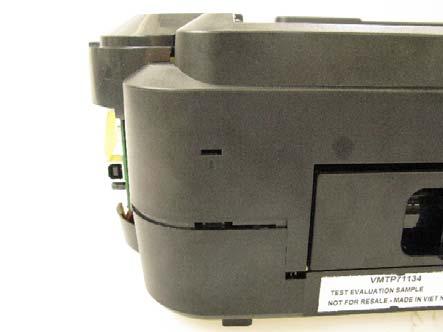
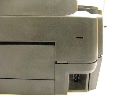
13 3) Remove the main case covers L and R. < While inserting a flat-blade screwdriver, etc. through into a space under the main case cover; and pressing the claw downward, slide the main case cover toward the front side of the printer. > 4) Remove the side cover L. 5) Remove the side cover R. (13/17)


 Remove the")
14 6) Remove the front door unit. < While slightly warping the center of the paper output tray downward, release the left and right bosses. > 7) Remove the panel cover unit (1 screw). (14/17)

")
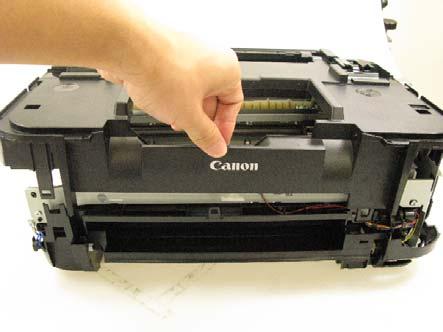
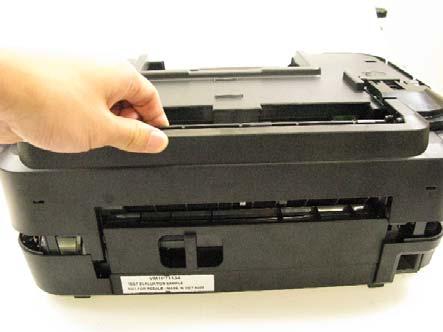
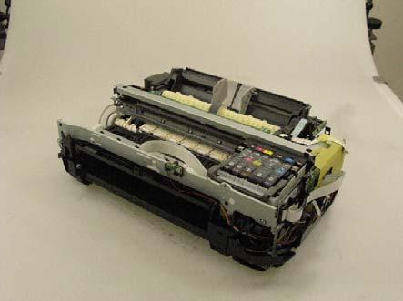
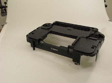
15 8) Remove the main case unit. (15/17)
 *2 1 Carriage rail The surface where the carriage unit slides (1) Floil")
 Floil KG107A 360 to 440 --- 4 Carriage rail The bottom surface where the bearing plate")
 Floil KG107A 270 to 330 --- 7 Parallel pin The pin surface which contacts the idler")
16 2-4. Grease Application No. Part name Where to apply grease / oil *1 Grease Grease amount (mg) *2 1 Carriage rail The surface where the carriage unit slides (1) Floil KG107A 270 to Carriage rail The surface where the carriage unit slides (2) Floil KG107A 18 to 36 1 x 2 3 Carriage rail The vertical surface where the bearing plate slides (3) Floil KG107A 360 to Carriage rail The bottom surface where the bearing plate slides (4) Floil KG107A 360 to Chassis The surface where the carriage slides (5) Floil KG107A 230 to Carriage upper rail The surface where the carriage slider moves (6) Floil KG107A 270 to Parallel pin The pin surface which contacts the idler pulley hole (7) Floil KG107A 9 to 18 1 x 1 *1: Drawing No. *2: Number of drops (1 drop = 9 to 18 mg) x locations (16/17)
17 2-5. Notes on Transportation This section describes the procedures for transporting the printer for returning after repair, etc. 1) In the service mode, press the Power button to finish the mode, and confirm that the paper lifting plate of the rear tray is raised. 2) Keep the print head and ink tanks installed in the carriage. See Caution (a) below. 3) Turn off the printer to securely lock the carriage in the home position. (When the printer is turned off, the carriage is automatically locked in place.) See Caution (b) below. Caution: a. If the print head is removed from the printer and left alone by itself, ink (the pigment-based black ink in particular) is likely to dry. For this reason, keep the print head installed in the printer even during transportation. b. Securely lock the carriage in the home position, to prevent the carriage from moving and applying stress to the carriage flexible cable, or causing ink leakage, during transportation. Note: If the print head must be removed from the printer and transported alone, attach the protective cap (used when the packing was opened) to the print head (to protect the print head face from damage due to shocks). (17/17)
MP240 / MP245 MP260 / MP268 MP480 / MP486 SIMPLIFIED SERVICE MANUAL
 MP240 / MP245 MP260 / MP268 MP480 / MP486 SIMPLIFIED SERVICE MANUAL QY8-13BV-000 Rev. 00: June 2008 Canon Inc. (1/13) TABLE OF CONTENTS 1. LIST OF ERROR DISPLAY / TROUBLESHOOTING 1-1. Operator Call Errors
QY8-13BN-000 COPYRIGHT 2007 CANON INC. CANON MP XX
 MP520 Service Manual Revision 0 QY8-13BN-000 Scope COPYRIGHT 2007 CANON INC. CANON MP520 072007 XX 0.00-0 This manual has been issued by Canon Inc., to provide the service technicians of this product with
PIXUS ip8600 PIXMA ip8500 SERVICE MANUAL
 PIXUS ip8600 PIXMA ip8500 SERVICE MANUAL Revision 0 QY8-13A5-000 COPYRIGHT 2004 CANON INC. CANON PIXUS ip8600/pixma ip8500 082004 XX 0.00-0 Scope This manual has been issued by Canon Inc., to provide the
MX880 series Service Manual
 MX880 series Service Manual (MX882 / MX883 / MX884 / MX885 / MX886 / MX888) Revision 0 QY8-13DF-000 COPYRIGHT 2011 CANON INC. CANON MX880 series 012011 XX 0.00-0 Scope This manual has been issued by Canon
PIXMA MP830 SERVICE MANUAL
 PIXMA MP830 SERVICE MANUAL Revision 0 QY8-3AN-000 COPYRIGHT 2006 CANON INC. CANON PIXMA MP830 022006 XX 0.00-0 Scope This manual has been issued by Canon Inc., to provide the service technicians of this
i70 SERVICE MANUAL Canon
 i70 SERVICE MANUAL Canon PIXUS 50i i70 SERVICE MANUAL Revision 0 QY8-1388-000 COPYRIGHT 2003 CANON INC. CANON PIXUS 50i / i70 102001 XX 0.00-0 PRINTED IN JAPAN (IMPRIME AU JAPON) Scope This manual has
MP630 MP638 QY8-31DE-000 COPYRIGHT 2008 CANON INC. CANON MP638/MP N REVISION 0
 MP630 MP638 REVISION 0 2920B001AA MP630 / 100V(JP) 2920B003AA MP630 / 120V(CA) 2920B006AA MP630 / 220V-240V(EUM) 2920B007AA MP630 / 220V-240V(EMB) 2920B008AA MP630 / 220V-240V(GB) 2920B011AA MP630 / 220V-240V(AU)
MP640 MP648 QY8-31DR-000 COPYRIGHT 2009 CANON INC. CANON MP648/MP N REVISION 0
 MP640 MP648 REVISION 0 3748B001AA MP640 / 100V(JP) 3748B002AA MP640 / 120V(US) 3748B003AA MP640 / 120V(CA) 3748B008AA MP640 / 220V-240V(EMB) 3748B009AA MP640 / 220V-240V(GB) 3748B011AA MP640 / 220V-240V(AU)
Removal and Installation8
 8 Screw Types 8-4 Top Cover Assembly 8-5 Left Hand Cover 8-6 Right Hand Cover 8-10 Front Panel Assembly 8-14 Left Rear Cover 8-15 Right Rear Cover 8-16 Extension Cover (60" Model only) 8-17 Media Lever
K Service Source. Color StyleWriter 2200
 K Service Source Color StyleWriter 2200 K Service Source Basics Color StyleWriter 2200 Basics Overview - 1 Overview The Color StyleWriter 2200 is a desktop color bubblejet printer for personal use. It
HP Deskjet 1510 series
 HP Deskjet 1510 series Table of contents 1 HP Deskjet 1510 series Help... 1 2 Get to know the HP Deskjet 1510 series... 3 Printer parts... 4 Control panel features... 5 Status light... 6 Auto-Off... 9
Datacard CR500 Instant Issuance System. User Reference Guide. July Rev B
 Datacard CR500 Instant Issuance System User Reference Guide July 2015 527495-001 Rev B Datacard CR500 User Reference Guide The CR500 Instant Issuance System Contents The CR500 Instant Issuance System The
Printing Your First Page. Attaching the Paper Support. Plugging in the Printer. Checking the Printer
 Printing Your First Page Attaching the Paper Support Checking the Printer Plugging in the Printer Installing the Ink Cartridges Installing the Printer Software Connecting the Printer 4011307 XXX-00 Attaching
MC-2984-V1.00. Troubleshooting. Advanced Guide. Basic Guide. Describes the summary of this product. Describes the detailed function of this product.
 ip4600 series On-screen Manual Стр. 1 из 396 стр. How to Use This Manual Printing This Manual MC-2984-V1.00 Basic Guide Describes the summary of this product. Advanced Guide Describes the detailed function
Installing the Printer Software
 4 Printing Your First Page Attaching the Paper Support 7 1 Checking the Printer 6 2 Plugging in the Printer 3 Installing the Ink Cartridges 5 Installing the Printer Software Connecting the Printer 4012581-00
fi-4120c Image Scanner
 P3PC-E007-01EN fi-4120c Image Scanner Cleaning and Maintenance 5 DAILY CARE This chapter describes how to clean the scanner. WARNING When cleaning the scanner, turn off the power, and unplug the AC cable
MC-2548-V1.00. Troubleshooting. Advanced Guide. Basic Guide. Describes the summary of this product. Describes the detailed function of this product.
 ip1900 series On-screen Manual Стр. 1 из 334 стр. How to Use This Manual Printing This Manual MC-2548-V1.00 Basic Guide Describes the summary of this product. Advanced Guide Describes the detailed function
Home... 3 Identify Product Parts... 5 Control Panel Buttons and Lights... 7 Load Paper... 9 Load Paper for Documents... 9 Load Envelopes...
 Home.................................................................. 3 Identify Product Parts..................................................... 5 Control Panel Buttons and Lights............................................
Fuser. Figure Remove the fuser assembly (1 of 2) 184 Chapter 5 Removal and replacement ENWW
 184 Chapter 5 Removal and replacement ENWW") Fuser 1. Remove the following assemblies. Scanner assembly. For the HP LaserJet 3015, see Scanner assembly. For the LaserJet 3020 and 3030, see Scanner assembly. Left cover. See Printer side covers. Rear
Fuser 1. Remove the following assemblies. Scanner assembly. For the HP LaserJet 3015, see Scanner assembly. For the LaserJet 3020 and 3030, see Scanner assembly. Left cover. See Printer side covers. Rear
CD-R Print Guide. Table of Contents QA V01. Preface 1. Introduction 1. Printing on CD-Rs/DVD-Rs (CD-R Direct Print) 2. Items to Prepare 2
 2. Items to Prepare 2") CD-R Print Guide Table of Contents Preface 1 Introduction 1 Printing on CD-Rs/DVD-Rs (CD-R Direct Print) 2 Items to Prepare 2 Cautions When Printing on CD-Rs/DVD-Rs 2 Attaching the CD-R Tray Feeder and
CD-R Print Guide Table of Contents Preface 1 Introduction 1 Printing on CD-Rs/DVD-Rs (CD-R Direct Print) 2 Items to Prepare 2 Cautions When Printing on CD-Rs/DVD-Rs 2 Attaching the CD-R Tray Feeder and
4.7. Image quality problems and solutions
 4.7. Image quality problems and solutions Print-quality defects can be attributed to printer components, consumables, media, internal software, external software applications and environmental conditions.
PrismJET DTx Quick Start Guide
 PrismJET DTx Quick Start Guide The following items are included in an accessory kit for your printer: USB Cable 110V Power Cord JetPRO 13/JetCUT Setup DVD User Guide CD Phillips Screwdriver Unpacking the
K Service Source. StyleWriter
 K Service Source StyleWriter K Service Source Basics StyleWriter Basics Introduction - 1 Introduction The StyleWriter is a serial bubble jet ink-on-demand printer. The StyleWriter prints up to 1/3 page
Quick Start Guide Ioline StudioJet
 Quick Start Guide Ioline StudioJet User Notice Trademarks Ioline StudioJet is a trademark of Ioline Corporation. HP is a trademark of the Hewlett-Packard Company. Other product names, logos, designs, titles,
MX920 series. Online Manual. Troubleshooting. English
 MX920 series Online Manual Troubleshooting English Troubleshooting The Machine Cannot Be Powered On Printing Does Not Start Paper Does Not Feed Properly/"No Paper" Error Occurs Print Results Not Satisfactory
PIXUS ip90 PIXMA ip90
 PIXUS ip90 PIXMA ip90 REVISION 0 9644A001AA 9644A002AA 9644A003AA 9644A005AA 9644A008AA 9644A009AA 9644A010AA 9644A011AA 9644A012AA 9644A013AA 9644A014AA 9644A015AA 9644A017AA PIXMA ip90/ 120V(US) PIXMA
LASERJET ENTERPRISE M604, M605, M606
 LASERJET ENTERPRISE M604, M605, M606 Maintenance kit replacement manual M604n M604dn M605x M605n M605dn M606x M606dn Conventions used in this guide TIP: Tips provide helpful hints or shortcuts. NOTE: Notes
Product Parts Front view... 2 Rear view... 2 Inside the product... 3 Scanner parts... 3 Control panel... 4
 Table of Contents Product Parts Front view................................................................. 2 Rear view.................................................................. 2 Inside the product...........................................................
Quick Reference. Understanding the Operator Panel. Understanding the operator panel lights. Quick Reference
 Quick Reference Understanding the Operator Panel The printer operator panel has two buttons and two lights. Lights indicate the status of the printer. Buttons are used to continue or cancel the current
Table of Contents. Unpacking and Inspection Setup Loading the Media Mount the Printer on the Wall... 16
 WPL25/WHC25 Table of Contents Unpacking and Inspection... 1 Setup... 5 Loading the Media... 6 Mount the Printer on the Wall... 16 LED and Button Functions... 17 Troubleshooting... 18 Unpacking and Inspection
Setup Guide. Confirming the Installation Space. Installation space (W x D x H) 70.5 x 66.3 x 61.5 inches (1790 x 1684 x 1560 mm) 23.
 70.5 x 66.3 x 61.5 inches (1790 x 1684 x 1560 mm) 23.") Introductory Information Setup Guide ENGLISH Read this manual before attempting to operate the printer. Keep this manual in a handy location for future reference. Caution Instructions in this Setup Guide
Introductory Information Setup Guide ENGLISH Read this manual before attempting to operate the printer. Keep this manual in a handy location for future reference. Caution Instructions in this Setup Guide
TOSHIBA Potable Printer B-EP4DL SERIES. Maintenance Manual. Document No. EO Original Sep., 2008 (Revised ) PRINTED IN JAPAN
 PRINTED IN JAPAN") TOSHIBA Potable Printer B-EP4DL SERIES Maintenance Manual Original Sep., 2008 (Revised ) Document No. EO18-33023 PRINTED IN JAPAN WARNING! Follow all manual instructions. Failure to do so could create
TOSHIBA Potable Printer B-EP4DL SERIES Maintenance Manual Original Sep., 2008 (Revised ) Document No. EO18-33023 PRINTED IN JAPAN WARNING! Follow all manual instructions. Failure to do so could create
Service Calibrations 5
 5 Service Calibrations 5-3 ing the Service Calibrations Menu 5-4 1. Scan-Axis Calibration 5-7 2. Service Station Calibration 5-11 3. Accuracy Calibration 5-14 Carriage Height Calibration 5-18 Calibration
HP Deskjet F2100 All-in-One series. Basics Guide
 HP Deskjet F2100 All-in-One series Basics Guide Hewlett-Packard Company notices The information contained in this document is subject to change without notice. All rights reserved. Reproduction, adaptation,
hp photosmart 7150 basics guide
 hp photosmart 7150 basics guide control panel The following table is a quick reference guide to the buttons that appear on your printer s control panel. CANCEL RESUME POWER contents 1 get started.........................................
Getting Started. Read Me First. series. Canon Inkjet Premium Photo Printer. 1 Preparation...P.1. Install the Print Head... P.3
 Canon Inkjet Premium Photo Printer series 1 Preparation...P.1 Getting Started Read Me First Symbols Used in This Document Prohibited actions. Instructions including important information. In this guide,
Windows is a registered trademark of Microsoft in the U.S. and other countries.
 User s Guide First Edition (February 1999) The following paragraph does not apply to any country where such provisions are inconsistent with local law: LEXMARK INTERNATIONAL, INC. PROVIDES THIS PUBLICATION
Removal and Installation 8
 Removal and Installation 8 8 Introduction 8-2 Service Calibration Guide to Removal and Installation 8-4 Window 8-8 Covers and Trims 8-12 Rear Tray 8-31 Rear Cover 8-32 Media Lever 8-33 Media Lever Position
Océ User manual. Océ CS2024. Quick Start Guide
 Océ User manual Océ CS2024 Quick Start Guide Océ Technologies B.V. Copyright 2005, Océ-Technologies B.V. Venlo, The Netherlands. All rights reserved. No part of this work may be reproduced, copied, adapted,
Calibration and Maintenance
 Epson DX5 X 1 Printhead Calibration and Maintenance 31 st Jan., 2013 Version V3.0 1 Contents Chapter 1: Computer Requirement...3 Chapter 2:Installation...4 Chapter 3:Characteristic...5 Chapter 4:Board
Laser Beam Printer. User's Guide
 Laser Beam Printer User's Guide Contents Turning the Printer ON/OFF (For 5910/5910F).......................... 3 Turning the Printer ON.................................................. 3 Turning the Printer
HP C6463A Two-Sided Printing Module User s Guide
 User's Guide HP C6463A Two-Sided Printing Module for use with the HP PhotoSmart P1000/P1100 Color InkJet Printer Table of Contents Overview............................................................................................
ipf610 SERVICE MANUAL DU OCTOBER 2007 REV. 0 fineline6 CANON imageprograf 610 REV. 0 PRINTED IN U.S.A.
 ipf60 SERVICE MANUAL DU7-243-000 OCTOBER 2007 REV. 0 COPYRIGHT 2007 CANON INC. CANON imageprograf 60 REV. 0 PRINTED IN U.S.A. Conten Contents Chapter PRODUCT DESCRIPTION. Product Overview..... Product
Windows is a registered trademark of Microsoft in the U.S. and other countries.
 User s Guide First Edition (February 1999) The following paragraph does not apply to any country where such provisions are inconsistent with local law: LEXMARK INTERNATIONAL, INC., PROVIDES THIS PUBLICATION
Field Replaceable Units (FRU) Parts List
 Parts List") Field Replaceable Units (FRU) Parts List This chapter provides a list of field replaceable units (FRU s) for the printer. Changes to Xerox parts are made to accommodate improved components as they become
Field Replaceable Units (FRU) Parts List This chapter provides a list of field replaceable units (FRU s) for the printer. Changes to Xerox parts are made to accommodate improved components as they become
Epson Stylus Photo 1410 Reference Guide 3 About Your Printer 3 About Exif Print 4 About Your Software 4 Printer Parts 5 Loading Paper 7 Single Sheets
 Epson Stylus Photo 1410 Reference Guide 3 About Your Printer 3 About Exif Print 4 About Your Software 4 Printer Parts 5 Loading Paper 7 Single Sheets 7 Envelopes 12 Special Papers 15 Printing with Windows
Start Here. Important setup information. Remove all tape and lift display. Locate components
 Start Here 1 Important setup information Wireless or wired network users: you must follow the instructions in this setup guide to be successful adding the HP All-in-One to your network. USB cable users:
Color Bubble Jet Printer. Quick Start Guide
 Color Bubble Jet Printer Quick Start Guide Canon i350/i250 Color Bubble Jet Printer Quick Start Guide. Copyright This manual is copyrighted by Canon U.S.A., Inc. with all rights reserved. Under the copyright
Updated 10/24/16 DAW
 Xerox WorkCentre 3215/3225 Service Manual Updated 10/24/16 DAW 702P02832 Main PL 1.1 Main... 5-3 ADF PL 1.2 ADF... 5-4 Covers PL 2.1 Covers... 5-5 Middle Cover PL 2.2 Middle Cover... 5-6 Frame PL 4.1 Frame...
ES1624 MFP Setup and Installation Guide
 ES1624 MFP Setup and Installation Guide Installation Overview Notes, Cautions, and Warnings...4 Select Location...4 Checking Package Contents...4 Scanning Unit... 4 Printing Unit... 4 Setting Up the Printing
MONARCH 9416 XL QUICK REFERENCE
 MONARCH 9416 XL QUICK REFERENCE This Quick Reference contains ribbon loading, supply loading, and general care, maintenance, and troubleshooting procedures for the 9416 XL Thermal Direct and 9416 XL Thermal
ipf5100 SERVICE MANUAL DU AUGUST 2007 REV. 0 fineline6
 ipf5100 SERVICE MANUAL DU7-1234-000 AUGUST 2007 REV. 0 COPYRIGHT 2006 CANON INC. CANON imageprograf ipf5100 REV. 0 PRINTED IN U.S.A. Conten Chapter 1 PRODUCT DESCRIPTION 1.1 Product Overview... 1-1 1.1.1
1. Front panel display. 2. Information button Some of the status messages that appear in the front panel are listed below:
 Front Panel s This topic includes: "Status s" on page 4-59 "Errors and Warnings" on page 4-60 Your printer s front panel provides you with information and troubleshooting help. When an error or warning
Photo Printer. Direct Printing Guide
 Photo Printer Direct Printing Guide Contents Contents Operation Panel Names and Functions Operation Panel.................................................................... 3 Icons on the LCD....................................................................
WorkForce Pro WP-4090 User's Guide
 WorkForce Pro WP-4090 User's Guide Contents WorkForce Pro WP-4090 User's Guide... 9 Product Basics... 10 Printer Parts Locations... 10 Printer Parts - Top... 11 Printer Parts - Back... 12 Printer Parts
K Service Source. Color StyleWriter 4100 and 4500
 K Service Source Color StyleWriter 4100 and 4500 K Service Source Basics Color StyleWriter 4000 Series Basics Overview - 1 Overview The Color StyleWriter 4000 Series printers are desktop color bubble-jet
ip3600 series Getting Started =Read Me First= Photo Printer
 Photo Printer ip3600 series Getting Started =Read Me First= Make sure to read this manual before using the printer. Please keep it in hand for future reference. Symbols The following symbols are used to
LASERJET ENTERPRISE MFP M630
 LASERJET ENTERPRISE MFP M630 Maintenance kit replacement manual M630dn M630f M630z M630h Copyright and License 2014 Copyright Hewlett-Packard Development Company, L.P. Reproduction, adaptation, or translation
Dynasty warriors 5 weapon guide >>>DOWNLOAD LINK<<< Pages printed; however. EN Printing a selftest
 Dynasty warriors 5 weapon guide. Do not feed a sheet of labels. Dynasty warriors 5 weapon guide >>>DOWNLOAD LINK
Lexmark X203n and X204n Series. Maintenance Guide
 Lexmark X203n and X204n Series Maintenance Guide February 2011 www.lexmark.com Contents...3 Cleaning the exterior of the printer...3 Cleaning the scanner glass...4 Cleaning the ADF separator rollers...5
Lexmark Z51. Color Jetprinter. User s Guide for OS/2
 Lexmark Z51 Color Jetprinter User s Guide for OS/2 First Edition (October 1998) The following paragraph does not apply to any country where such provisions are inconsistent with local law: LEXMARK INTERNATIONAL,
WF-7110 User's Guide
 WF-7110 User's Guide Contents WF-7110 User's Guide... 9 Product Basics... 10 Setting Up the Control Panel... 10 Control Panel Buttons and Lights... 10 Status Icons... 11 Setting a Password and Locking
4.1 General. 4 Replacement Procedures
 4.1 General This chapter explains how to disassemble the computer and replace Field Replaceable Units (FRUs). It may not be necessary to remove all the FRUs in order to replace one. The chart below is
Photo Printer. Quick Start Guide
 Photo Printer Quick Start Guide Getting Help from Canon Help Us Help You Better Before you contact Canon, please record the following information. Serial Number (located on the inside of the printer):
HP Photosmart c3180 Main Circuit Board Replacement
 HP Photosmart c3180 Main Circuit Board Replacement Replacing a faulty main circuit board. Written By: Jim ifixit CC BY-NC-SA www.ifixit.com Page 1 of 26 TOOLS: Spudger (1) T10 Torx Screwdriver (1) ifixit
Chapter 4 Replacement Procedures
 Chapter 4 Replacement Procedures 4 4-ii Satellite P30 Series Maintenance Manual Chapter 4 Contents 4.1 General... 4-1 4.2 Battery... 4-7 4.3 PC Card... 4-8 4.4 HDD... 4-10 4.5 Optical Drive Module... 4-12
Unpacking and Installing the Flora 2512 UV Printer. Steps 1: Unscrew the 10mm bolts holding the top. Then remove the top and put in a safe place.
 Unpacking and Installing the Flora 2512 UV Printer Steps 1: Unscrew the 10mm bolts holding the top. Then remove the top and put in a safe place. Step 2: Unscrew 10mm bolts holding the end panels. On the
Getting Started. Read Me First. series. Photo Printer
 Photo Printer series Getting Started Read Me First Make sure to read this manual before using the printer. Please keep it in hand for future reference. Contents 1 Preparation 2 Turn the Power On 3 Install
Lexmark Z51. Color Jetprinter. User s Guide for Windows NT 4.0
 Lexmark Z51 Color Jetprinter User s Guide for Windows NT 4.0 First Edition (October 1998) The following paragraph does not apply to any country where such provisions are inconsistent with local law: LEXMARK
Edition notice. Edition: June 2000
 Edition notice Edition: June 2000 The following paragraph does not apply to any country where such provisions are inconsistent with local law: LEXMARK INTERNATIONAL, INC., PROVIDES THIS PUBLICATION AS
Colour Set-up Version 7.1
 1 of 35 Colour Set-up Version 7.1 REVISION HISTORY Date Rev Description Author Approved 4/07/14 G Various updates including Win8. CW/FMC/DMG 26/05/15 G Updated to include ICC Profiles NM 2 of 35 Table
CASH DISPENSING UNIT (MODEL: GLOBAL BILL MODULE, GBM) OPERATOR MANUAL
 OPERATOR MANUAL") CASH DISPENSING UNIT (MODEL: GLOBAL BILL MODULE, GBM) OPERATOR MANUAL Jun. 2002. Taenam Information and Communication Co.Ltd., R&D Laboratory Checked 05-07-19 1 Document History NO History Date Writer
CASH DISPENSING UNIT (MODEL: GLOBAL BILL MODULE, GBM) OPERATOR MANUAL Jun. 2002. Taenam Information and Communication Co.Ltd., R&D Laboratory Checked 05-07-19 1 Document History NO History Date Writer
Getting Started. Read Me First. series. Photo Printer
 Photo Printer series Getting Started Read Me First Make sure to read this manual before using the printer. Please keep it in hand for future reference. Symbols Used in This Document Instructions including
3 Maintenance. Chapter contents
 3 Maintenance Chapter contents Life expectancies of consumables..................... 40 User-replaceable parts.............................. 40 Replacing the printer pickup roller................ 41 Replacing
USING ABSOLUTE BLACK INKS FOR MAKING SCREEN POSITIVES ON THE EPSON STYLUS PRO 7700, 7890, 7900, 9700, 9890, & 9900
 USING ABSOLUTE BLACK INKS FOR MAKING SCREEN POSITIVES ON THE EPSON STYLUS PRO 7700, 7890, 7900, 9700, 9890, & 9900 The following instructions explain how the i2i Absolute Black ink for making screen positives
www MK-Electronic de Business InkJet 3000dtn HP Parts Reference Guide Cables Chassis Parts Electronic Accessories Electronics/Power Supply Cable Base
 Cables Cable 1 C8116-67037 Power supply harness 2 C8116-67042 Trailing cable - Connects from the carriage PC board to the main logic PC board Chassis Parts Base 3 C8116-67001 Base assembly - Main frame
Start Here. Remove all tape and lift display. Locate components USB
 HP Photosmart 2600/2700 series all-in-one User Guide Start Here 1 USB Important: Do not connect the USB cable until this guide instructs you to or the software may not install properly. If you have problems
Codonics Horizon User s Manual
 Codonics Horizon User s Manual GS/G2/G1 Addendum Codonics Horizon User s Manual Addendum Summary The latest versions of Horizon GS/G2/G1 Imager utilize hardware and software that is not compatible with
Unpack the machine and its components. Cassette/Multi-purpose tray
 Set-Up Sheet Thank you for purchasing the Canon imageclass D320. To get your machine ready for use, please follow the instructions in this Set-Up Sheet before referring to any other documentation. Unpack
Microline 420/421 & 490/491
 Check the contents: 1. Printer 2. Ribbon cartridge 3. Power Cable 4. CD with drivers and online User Guide 5. Setup Guide 2 1. 2. 1. Grasp tabs (1) and open access cover (2). 2. Remove printhead shipping
learn about the printer... 1
 quick help hp deskjet 845c/825c series table of contents learn about the printer.......................... 1 introducing the hp deskjet 845c/825c series printer............ 2 terms and conventions.................................
Quick Start Guide BUBBLE JET PRINTER. Table of Contents QA V01. Preface 1. Shipping Materials 1. Introduction 1.
 BUBBLE JET PRINTER Quick Start Guide Table of Contents Preface 1 Shipping Materials 1 Introduction 1 Setting Up 2 Preparing the Printer 2 Installing the Print Head 3 Connecting the Printer to the Computer
Product Support Bulletin
 EPSON AMERICA INC. EPSON Product Support Bulletin Subject: Laser & Non-Impact Printer Error Codes Date: 4/3/91 PSB No: P-0077 Page(s): 1 of 11 Originator: JV Epson printers issue beep tones and/or displays
Troubleshooting with the LCD Error Message Table
 Troubleshooting with the LCD Error Message Table LCD Error Message Cause Solution Calibrate Failed No. 155 and 170) Calibrate Film No. 159) Calibrate Ribbon Nos. 128 and 170) Card Feed Stop No. 137) Card
HP DeskJet 2130 All-in-One series
 HP DeskJet 2130 All-in-One series Table of contents 1 HP DeskJet 2130 series Help... 1 2 Get started... 3 Printer parts... 4 Control panel features... 5 Status lights... 6 Load media... 10 Load an original
AstroJet TM M2 Quick Start Guide
 AstroJet TM M2 Quick Start Guide Step 1 Remove Printer and Accessories from packaging. Place Printer on a flat, even surface. Step 2 Remove Service Station Transport Tab 1. Open Top Cover. 2. Open Print
Contents L4160 User's Guide Product Basics Wi-Fi Networking... 30
 L4160 User's Guide Contents L4160 User's Guide... 11 Product Basics... 12 Using the Control Panel... 12 Control Panel Buttons and Lights... 13 Status Icon Information... 13 Entering Characters on the
Xerox Nuvera Quick Start Cards
 October 2015 702P03887 Xerox Nuvera Quick Start Cards Xerox Nuvera 100/120/144/157 EA Production System Xerox Nuvera 100/120/144 MX Production System Table of Contents Supplies Provides information about
ASK Printer Driver
 ASK 2500 Printer Driver INSTRUCTION MANUAL V1.00 August, 2009 1/19 1. Applicable OS... 3 2. Recommended PC conditions... 3 3. To install Printer Driver... 4 4. Functions... 5 4.1. Display Version
Interpret control-panel messages
 Interpret control-panel messages Control-panel message types Four types of control-panel messages can indicate the status of or problems with the product. Message type Status messages Warning messages
Installation Guide. English. HP LaserJet 5, 5M and 5N Printer Duplex Printing Accessory (C3920A)
") Installation Guide English HP LaserJet 5, 5M and 5N Printer Duplex Printing Accessory (C3920A) Copyright Hewlett- Packard Company 1996 All Rights Reserved. Reproduction, adaptation, or translation without
Installation Guide English HP LaserJet 5, 5M and 5N Printer Duplex Printing Accessory (C3920A) Copyright Hewlett- Packard Company 1996 All Rights Reserved. Reproduction, adaptation, or translation without
imagine. print. create. Edible Printing Insights SET UP AND TROUBLE SHOOTING GUIDE
 imagine. print. create. Edible Printing Insights SET UP AND TROUBLE SHOOTING GUIDE Warranty 1 Edible Printing System Warranty All printing systems are benefitted by a 12-month warranty that commences on
4.8. Other Errors Image system problem
 4.8. Other Errors 4.8.1. Image system problem No Problem Description Troubleshooting Page 1 Toner cartridge detection error P.4 242 2 Image registration problem occurs after ACR (Auto Color Registration)
TONER CARTRIDGE REMANUFACTURING INSTRUCTIONS HP LASERJET 4600 TONER CARTRIDGE
 HP LASERJET 4600 TONER CARTRIDGE REMANUFACTURING INSTRUCTIONS HP LASERJET 4600 TONER CARTRIDGE REMANUFACTURING THE HP LASERJET 4600 TONER CARTRIDGE By Javier Gonzalez and the Technical Staff at UniNet
CX-G6400. User's Guide COLOR CARD PRINTER CANON FINETECH NISCA INC Y
 CX-G6400 COLOR CARD PRINTER User's Guide CANON FINETECH NISCA INC. 2017 4Y1-8612-010 Table of Contents Before You Begin Conventions 1 Sample Screens 1 Trademarks 1 Abbreviations 2 Important Notices 2 Legal
www MK-Electronic de DeskJet 540 HP Parts Reference Guide Electronics/Power Supply External Case Parts PC Board Power Cord Power Module Base Cover
 ElectronicsPower Supply PC Board 1 C2162-67810 Sensor PC board - Contains optical media sensors and mechanical switch for access door 2 C2162-69005 Main logic board - Includes logic, power supply, motor
ES5500 USER MANUAL. Pressure Sealer
 ES5500 USER MANUAL Pressure Sealer This manual provides detailed information on how to operate and maintain your ES5500. Please read this manual before operating the machine in order to prevent any damage
Cutter Option Installation Instructions
 This kit includes the parts and documentation necessary to install the cutter option on the Zebra XiII, XiIII, and XiIIIPlus-Series printers. NOTE: The Cutter Option is not available for the 96XiIII. Adding
Rack Installation Instructions
 Rack Installation Instructions For System Storage EXP2512 and EXP2524 Express Storage Enclosures Use the instructions in this document to install an IBM System Storage EXP2512 Express Storage Enclosure
Troubleshooting with the control panel
 Troubleshooting with the control panel The tables in this section explain common messages that might appear on the control-panel display. Within each table, the messages and their meanings are listed in