7. PCB AND FUNCTIONS
|
|
|
- Cora Rose
- 6 years ago
- Views:
Transcription
1 Contents. PCB AND FUNCTIS. Outdoor Unit Control PCB Outdoor Unit Control PCB CR-C0DXH Outdoor Unit FAN PCB FAN-C00DXH Outdoor Unit FAN PCB FAN-C0DXH Outdoor Unit Filer PCB FIL-C0DXH Outdoor Unit HIC Board HIC-C0DXH Functions (for CR-C0DXH) Indoor Unit Control PCB Switches and Functions For AC Fan Motor (CR-UXRPB-P / F, R, P and E types) For AC Fan Motor (CR-UXRPB-PE / L type) For DC Fan Motor (CR-SXRPB-B / T and D types) Only for -Way cassette (CR-SX0EQ / U type) Only for -Way cassette 0 0 (CR-XM0XH, POW-XM0XH / Y type) Only for Slim Low Static Ducted (CB-US0XH / M type) CR (for CR-K0XH / S-MKE / MKE / MKE) (Wall Mounted) CR (for CR-KXH / S-MKE / MKE / MKE / 0MKE) (Wall Mounted)

 fuse (F0) (CN0)")
 S00 CTN, CTL S00 Alarm LED D0(LED)")
 RC plug (CN0) CT, CT OC plug (CN00) High-pressure sensor")
 Oil detection sensor (OIL,,) Comp. Liquid temp.")
 (DISCH) - Suction temp.")
2 PCB and Functions. Outdoor Unit Control PCB -. Outdoor Unit Control PCB CR-C0DXH S00 S00 S00 A. ADD pin (CN0) AP pin RUN pin CHK pin (CN00) (CN0) (CN0) STOP pin Control circuit TEST pin OAC pin (CN0) fuse (F0) (CN0) (CN0) Power LED (D) HIC HIC HIC HIC Snow senser (CN0) HIC S00 S00 HIC MODE pin (CN0) S00 CTN, CTL S00 Alarm LED D0(LED) D0(LED ) Terminal plug (CN0) RC plug (CN0) EEPROM memory IC (IC0) RC plug (CN0) CT, CT OC plug (CN00) High-pressure sensor (HPS) Low-pressure sensor (LPS) Comp. discharge temp. (DISCH) Oil detection sensor (OIL,,) Comp. Liquid temp. discharge sensor at heat temp. exchanger, (DISCH) (EXL,) Comp. Outdoor discharge air temp. temp. (AIR TEMP) (DISCH) - Suction temp. (SCT) Gas temp. sensor at heat exchanger, (EXG,) EMG plug (CN0)


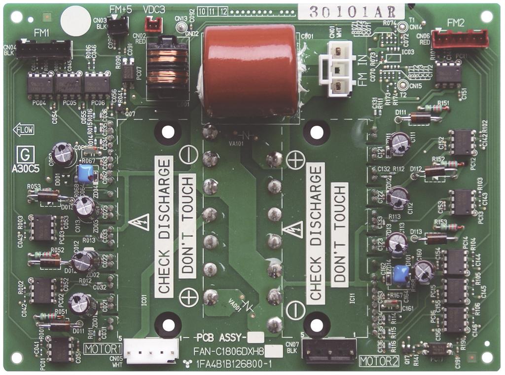
3 PCB and Functions. Outdoor Unit Control PCB -. Outdoor Unit FAN PCB FAN-C00DXH -. Outdoor Unit FAN PCB FAN-C0DXH -


4 . Outdoor Unit Control PCB -. Outdoor Unit Filer PCB FIL-C0DXH -. Outdoor Unit HIC Board HIC-C0DXH -
5 . Outdoor Unit Control PCB -. Functions (for CR-C0DXH) Automatic address setting (CN0) P plug (white): Automatic address setting pin Short-circuit this pin for second or longer to automatically set the addresses at the indoor units that are connected to that outdoor unit and are within the same system. The system address is "" at the time of shipment. Automatic address setting is necessary even for communications lines in a single system where the inter-unit control wiring does not cross to any other systems. While automatic address setting is in progress, the LEDs (LED, : red) on the outdoor unit control PCB blink alternately. (Short-circuiting this pin while automatic address setting is in progress will stop the automatic address setting operation.) S00 S00 S00 S00 S00 S00 S00 Rotary switch (0 positions, black): Outdoor system address setting switch The setting is "" at the time of shipment. It is not necessary to change the setting if wiring is connected only to an outdoor unit and indoor units in a single system and the inter-unit control wiring does not cross multiple systems. If wiring links the inter-unit control wiring for multiple systems to the same communications lines, then a different address must be set for each refrigerant tubing system. If wiring links multiple systems, a maximum of 0 systems (up to indoor units) can be connected. This setting can be set up to "," however control will be for 0 systems even if the setting is set to higher than 0. An alarm will be displayed if system addresses are duplicated. (For details, refer to Table -.) DIP switch (P, blue): Switches for setting system address 0s digit and 0s digit If 0 systems or more are set, the setting is made by a combination of this DIP switch and S00. If 0 - systems are set, set switch (0s digit) to. If 0 - systems are set, set switch (0s digit) to, and set switch (0s digit) to. If 0 systems are set, set both switch (0s digit) and switch (0s digit) to. (For details concerning S00 and S00, refer to Table -.) Rotary switch (0 positions, red): Switch for setting the number of connected indoor units. In order to allow the outdoor unit to manage indoor units in the same refrigerant system, set the number of connected indoor units. (For details, refer to Table -.) DIP switch (P, blue): Switches for setting the 0s, 0s, and 0s digit for the number of connected indoor units If 0 systems or more are set, the setting is made by a combination of this DIP switch and S00. If 0 - systems are set, set only switch (0s digit) to. If 0 - systems are set, set switch (0s digit) to, and set switch (0s digit) to. If 0 - systems are set, set only switch (0s digit) to. (For details concerning S00 and S00, refer to Table -.) DIP switch (P, blue): Switch for setting the number of outdoor units Turn the switches according to the number of outdoor units ( - ). (For details, refer to Table -.) DIP switch (P, blue): Unit No. setting switch The setting is "" at the time of shipment. (For details, refer to Table -.) DIP switch (P, blue): Backup operation switch If an INV compressor has malfunctioned, turn CT and Back Up SW to operate the outdoor unit using only the constant-speed compressor. If a constant-speed compressor has malfunctioned, turn CT and Back Up SW to operate the outdoor unit using only the INV compressor. (Disconnect the wiring from the constant-speed compressor.) -
6 . Outdoor Unit Control PCB Terminal plug (CN0) P plug (black): For communications circuit impedance matching A connecting socket (P, black) is attached to the terminal plug at the time of shipment from the factory. In the case of link wiring which combines the inter-unit control wiring for multiple systems into a single communications circuit, leave the connecting socket in place at only one of the outdoor units, and move the socket from the "SHORT" side to the "OPEN" side at all other outdoor units. If multiple connecting sockets are left in place, communications trouble will occur. LED, D0, D0 Power LED D Run (CN0) Stop (CN0) AP (CN00) Mode (CN0) Test (CN0) LED (red ) LED and blink alternately while automatic address setting is in progress. Display the alarm contents for alarms which were detected by the outdoor unit. LED (red): Power indicator Indicates the DC V power on the outdoor unit control PCB. P plug (white): Start pin Short-circuit this pin and apply a pulse signal to start all indoor units in that refrigerant system. P plug (white): Stop pin Short-circuit this pin and apply a pulse signal to stop all indoor units in that refrigerant system. P plug (white): Vacuuming pin To perform vacuuming of the outdoor unit, short-circuit this pin and then turn the power. All solenoid valves turn and vacuuming begins smoothly. (Do not perform automatic address setting at this time.) Release the short-circuit to return the unit to normal status. P plug (white): Indoor unit Heating/Cooling mode change pin When operating the compressors to perform automatic address setting, operation in Heating mode can be normally used. However, short-circuiting this pin performs operation in Cooling mode. (Static signal) Short-circuiting this pin during ordinary operation changes the mode from Cooling to Heating (if the current mode is Cooling) or from Heating to Cooling (if the current mode is Heating). P plug (white) This pin is used to test the PCB at the factory. When the power is turned after this pin has been short-circuited, all output signals will be output in sequence. (Sequential output does not occur if this pin is short-circuited when the power is already.) Releasing this pin returns the unit to normal control. -
7 . Outdoor Unit Control PCB Table -. Setting the System Address [S00: Rotary switch (black), S00: P DIP (blue)] refrigerant system only Link wiring Outdoor system address 0 S00 setting Table -. Setting the Number of Indoor Units [S00: Rotary switch (red), S00: P DIP (blue)] Number of Indoor Units S00 Setting P (0s digit) S00 setting P (0s digit) S00 Setting Link wiring Outdoor system address 0 0 S00 setting 0 0 Table -. Setting the Number of Outdoor Units [S00: DIP switch (blue)] Number of Indoor Units Table -. Setting the Outdoor Unit address Outdoor Unit Address P (0s digit) S00 setting P (0s digit) S00 Setting S00 Setting
8 . Indoor Unit Control PCB Switches and Functions Indoor Unit Control PCB Switches and Functions Indoor unit control PCB T0: P plug (yellow): Used for remote control. (Refer to the remote control section.) (CN0) Control items: () Start/stop input () Remote controller prohibit input () Start signal output () Alarm signal output EXCT: (CN0) DISP: (CN0) (CN0) P plug (red): Can be used for demand control. When input is present, forces the unit to operate with the thermostat. P plug (white): Short-circuiting this plug allows the unit to be operated by the remote controller, even if it is not connected to an outdoor unit. (In this case, alarm "E0," which indicates trouble in the serial communication between the indoor and outdoor unit, does not occur.) CHK: P plug (white): Test pin. Short-circuiting this pin allows the indoor FM (H fan speed), drain pump, fl ap motor (F (CN0) position), and electronic expansion valve full-open position to be checked. (CN0) However this function turns if the indoor unit protection mechanism is activated. The unit can be operated even if the remote controller and outdoor unit are not connected. However even if the remote controller cannot is connected, it cannot be used to operate the unit. This function can be used for short-term tests. JP: (J00) Jumper wire: Allows selection of the T0 terminal start/stop signal. (Refer to the remote control section.) Status at shipment: Pulse signal Jumper wire cut: Static signal (continuous signal) FAN DRIVE P plug (white): This terminal sends a signal to the ventilation fan when the FAN button on the wired remote controller is used to operate a commercially-available ventilation fan. (Refer to the remote control section.) (CN0) Use a ventilation fan which can accept no-voltage A contact as the external input signal. Power LED: LED (red): Illuminates when power is supplied. Blinks when there is a failure in the EEPROM (IC0: nonvolatile (D00) memory). EEPROM: Nonvolatile memory: Memory which stores the unit type data and other information. When the PCB is replaced, (IC00) remove the EEPROM from the old PCB and install it onto the new PCB. If an IC failure occurs, replace with a new IC which was provided with the service PCB, and set the necessary information from the wired remote controller. (For the procedure, refer to the servicing technical materials.) GRL: (CN00) For AC fan motor (CR-UXRPB-P (or CR-UXRPB-PE) : P (yellow)) For DC fan motor (CR-SXRPB-B : P (blue)) The indoor unit power terminal plate may be a P type, P type or may be a P type. (Refer to the fi gure at below.) The basic wiring diagram shows the P-type terminal plate. Therefore the terminal plate may differ from the illustrations. P terminal board P terminal board P terminal board (L) (N) U U R R Power Unit Remote supply control control line line T, F, E, D, L Types L N U U R R Power Unit Remote supply control control line line U, Y, M, P, R Types L N U U Power supply Unit control line K Type -
 POWER LED (D00) EEPROM (IC00) EMG (CN0) OC (CN00) FAN DRIVE (CN0) EXCT (CN0) JP00 GRL (CN00) DISP (CN0) CHK (CN0) T0 (CN0) -.")
9 . Indoor Unit Control PCB Switches and Functions -. For AC Fan Motor (CR-UXRPB-P/ F, R, P and E types) POWER LED (D00) EEPROM (IC00) EMG (CN0) OC (CN00) FAN DRIVE (CN0) EXCT (CN0) JP00 GRL (CN00) DISP (CN0) CHK (CN0) T0 (CN0) -. For AC Fan Motor (CR-UXRPB-PE/ L type) EEPROM (IC00) POWER LED (D00) EMG (CN0) OC (CN00) EXCT (CN0) GRL (CN00) DISP (CN0) JP00 FAN DRIVE (CN0) CHK (CN0) T0 (CN0) -
 EEPROM (IC00) POWER LED (D00) JP00 GRL (CN00) EXCT (CN0)")
 FAN DRIVE (CN0) POWER LED (D00) EEPROM (IC00) GRL (CN00) T0")
10 . Indoor Unit Control PCB Switches and Functions -. For DC Fan Motor (CR-SXRPB-B/ T and D types) EEPROM (IC00) POWER LED (D00) JP00 GRL (CN00) EXCT (CN0) DISP (CN0) OC (CN00) FAN DRIVE (CN0) T0 (CN0) CHK (CN0) EMG (CN0) -. Only for -Way cassette (CR-SX0EQ/ U type) FAN DRIVE (CN0) POWER LED (D00) EEPROM (IC00) GRL (CN00) T0 (CN0) JP00 CHK (CN0) OC (CN00) VARISTOR (VA00) EXCT (CN0) DISP (CN0) EMG (CN0) -0
 POWER LED")
 JP00 EEPROM memory IC JP00 OC (CN00) FAN DRIVE (CN0) EMG")
11 . Indoor Unit Control PCB Switches and Functions -. Only for -Way cassette 0 0 (CR-XM0XH, POW-XM0XH/ Y type) POWER LED (D00) CHK (CN0) DISP (CN0) TEST (CN0) EXCT (CN0) FILTER (CN00) T0 (CN0) OPTI (CN00) JP00 EEPROM memory IC JP00 OC (CN00) FAN DRIVE (CN0) EMG (CN0) CR-XM0XH POW-XM0XH -
 EEPROM (IC00) POWER LED (D00) JP00 GRL (CN00) EXCT (CN0) DISP")
12 . Indoor Unit Control PCB Switches and Functions -. Only for Slim Low Static Ducted (CB-US0XH/ M type) EEPROM (IC00) POWER LED (D00) JP00 GRL (CN00) EXCT (CN0) DISP (CN0) OC (CN00) FAN DRIVE (CN0) T0 (CN0) CHK (CN0) EMG (CN0) -
 (Wall Mounted) Power LED (D00) EMG plug OC plug EXCT plug Indoor heat exchanger (E) sensor Indoor heat exchanger (E) sensor DISP pin")
13 . Indoor Unit Control PCB Switches and Functions Indoor Unit Control PCB -. CR (for CR-K0XH/S-MKE/MKE/MKE) (Wall Mounted) Power LED (D00) EMG plug OC plug EXCT plug Indoor heat exchanger (E) sensor Indoor heat exchanger (E) sensor DISP pin Microcomputer T0 plug JP00 Nonvolatile memory IC Room temperature (TA) sensor CHK (test) pin -
 (Wall Mounted) OC plug EMG plug Power LED (D00) T0 plug Indoor heat exchanger (E) sensor EXCT plug Indoor heat exchanger (E) sensor Room")
14 PCB and Functions. Indoor Unit Control PCB Switches and Functions Indoor Unit Control PCB -. CR (for CR-KXH/S-MKE/MKE/MKE/0MKE) (Wall Mounted) OC plug EMG plug Power LED (D00) T0 plug Indoor heat exchanger (E) sensor EXCT plug Indoor heat exchanger (E) sensor Room temperature (TA) sensor CHK (test) pin DISP pin Microcomputer Nonvolatile memory IC JP00 -
UNIT CONTROLLER 7 (UC7) Operation & Installation. Hydronic Units
 Operation & Installation. Hydronic Units") UNIT CONTROLLER 7 (UC7) Operation & Installation Hydronic Units Date: 1 November 2012 Issue: 5 Page 1 of 17 Contents 1. Connections, hydronic unit... 3 2. Functions assigned to SSR1, SSR2 and AUX... 3
UNIT CONTROLLER 7 (UC7) Operation & Installation Hydronic Units Date: 1 November 2012 Issue: 5 Page 1 of 17 Contents 1. Connections, hydronic unit... 3 2. Functions assigned to SSR1, SSR2 and AUX... 3
IntesisBox ModBus RTU Fujitsu Air Conditioning
 IntesisBox ModBus RTU Fujitsu Air Conditioning Compatible with Domestic and VRF line air conditioners commercialized by Fujitsu User Manual 03/2019 r1.0 eng Intesis Software S.L.U. 2019 All Rights Reserved.
IntesisBox. v.2.5. User Manual Issue Date: 12/2017 r1.9 EN. Modbus RTU (EIA-485) Interface for Fujitsu air conditioners.
 Interface for Fujitsu air conditioners.") IntesisBox FJ-RC-MBS-1 v.2.5 Modbus RTU (EIA-485) Interface for Fujitsu air conditioners. User Manual Issue Date: 12/2017 r1.9 EN Order Codes: FJ-RC-MBS-1: Modbus RTU Interface for Fujitsu air conditioners
IntesisBox FJ-RC-MBS-1 v.2.5 Modbus RTU (EIA-485) Interface for Fujitsu air conditioners. User Manual Issue Date: 12/2017 r1.9 EN Order Codes: FJ-RC-MBS-1: Modbus RTU Interface for Fujitsu air conditioners
IntesisBox. v.1.3. User Manual Issue Date: 04/2016. IntesisBox PA-RC2-MBS-4
 IntesisBox PA-RC2-MBS-4 v.1.3 MODBUS RTU (EIA485) Interface for Panasonic and Sanyo air conditioners. Compatible with ECOi and PACi line models. User Manual Issue Date: 04/2016 Order Codes: PA-RC2-MBS-4
Slim Ducted type. Contents MMD-AP 4SPH2UL MMD-AP0094SPH2UL MMD-AP0124SPH2UL MMD-AP0154SPH2UL MMD-AP0184SPH2UL
 E5-3I D-AP 4SP2U Slim Ducted type D-AP0074SP2U D-AP0094SP2U D-AP024SP2U D-AP054SP2U D-AP084SP2U Contents. Specifications 2. Dimensions 3. Center of gravity 4. Piping diagram 5. Wiring diagram 6. Electrical
IntesisBox. v.0.1. User Manual Issue Date: 12/2017 r1.3 EN
 IntesisBox HS-RC-MBS-1 v.0.1 Modbus RTU (EIA-485) Interface for Hisense air conditioners. Compatible with commercial line of air conditioners commercialized by Hisense. User Manual Issue Date: 12/2017
COMFORT CONTROL CENTER SERVICE INSTRUCTIONS
 USA SERVICE OFFICE Dometic Corporation 2320 Industrial Parkway Elkhart, IN 46516 574-294-2511 CANADA Dometic Corporation 46 Zatonski, Unit 3 Brantford, ON N3T 5L8 CANADA 519-720-9578 For Service Center
IntesisBox TO-RC-MBS-1
 IntesisBox TO-RC-MBS-1 v.1.5 MODBUS RTU (EIA485) Interface for Toshiba air conditioners from the Digital Inverter & VRF lines. User Manual Issue Date: 01/2014 Order Codes: TO-RC-MBS-1 Intesis Software
IntesisBox PA-AC-MBS-1
 IntesisBox PA-AC-MBS-1 v.2.3 Modbus RTU (EIA-485) Interface for Panasonic air conditioners. Compatible with Etherea line air conditioners commercialized by Panasonic. User s Manual Issue Date: 11/2017
Wiring Diagrams DIAGRAM INDEX. POWER SCHEMATICS Unit 30GXN,R Voltage Figure Number
 30GXN,R Sizes 080-528 Air-Cooled Chillers with ComfortLink Controls 50/60 Hz Wiring Diagrams DIAGRAM INDEX POWER SCHEMATICS Unit 30GXN,R Voltage Figure Number Label Diagram No. 30GX 080-178* ALL 1 505429
The PanasonicVRF Driver
 The PanasonicVRF Driver The PanasonicVRF driver interfaces to a Panasonic or Sanyo variable refrigerant flow (VRF) air conditioning system. Compatible VRF systems include Panasonic ECOi, ECO G, and Sanyo
Modbus RTU (EIA-485) Interface for Panasonic and Sanyo air conditioners. Compatible with ECOi and PACi line models.
 Interface for Panasonic and Sanyo air conditioners. Compatible with ECOi and PACi line models.") IntesisBox PA-RC2-MBS-1 v.2.3 Modbus RTU (EIA-485) Interface for Panasonic and Sanyo air conditioners. Compatible with ECOi and PACi line models. User Manual Issue Date: 11/2017 r2.3 EN Order Codes: PA-RC2-MBS-1:
IntesisBox PA-RC2-MBS-1 v.2.3 Modbus RTU (EIA-485) Interface for Panasonic and Sanyo air conditioners. Compatible with ECOi and PACi line models. User Manual Issue Date: 11/2017 r2.3 EN Order Codes: PA-RC2-MBS-1:
IntesisBox DK-RC-MBS-1 v.0.8
 IntesisBox DK-RC-MBS-1 v.0.8 MODBUS RTU (RS-485) Interface for Daikin air conditioners. Compatible with VRV and SKY line air conditioners commercialized by Daikin. User Manual Issue Date: 2013/02/26 Order
DESIGN & TECHNICAL MANUAL
 AIR CONDITIONER Duct type DESIGN & TECHNICAL MANUAL INDOOR ARYG72LHTA ARYG90LHTA OUTDOOR AOYG72LRLA AOYG90LRLA DR_AR012EF_03 2017.04.07 Notices: Product specifications and design are subject to change
IntesisBox DK-RC-MBS-1 v.0.2
 IntesisBox DK-RC-MBS-1 v.0.2 MODBUS RTU (RS-485) Interface for Daikin air conditioners. Compatible with VRV and SKY line air conditioners commercialized by Daikin. User Manual Issue Date: 2011/05/05 Order
Pocket Quick. Reference Guide. On the TOSHIBA RBC-AMS51E. Remote Controller
 Pocket Quick Reference Guide On the TOSHIBA RBC-AMS51E Remote Controller Quick Reference Guide To assist service engineers working on Toshiba air conditioning equipment, there is a large quantity of data
SERVICE Manual DUCT TYPE AIR CONDITIONER. (Cool) OUTDOOR UNIT INDOOR UNIT TYPE UDH4400G DH44ZAX IDH4400A DH44ZA1(A2) ADH4400G DH44ZA1(A2)
 OUTDOOR UNIT INDOOR UNIT TYPE UDH4400G DH44ZAX IDH4400A DH44ZA1(A2) ADH4400G DH44ZA1(A2)") DUCT TYPE AIR CONDITIONER (Cool) TYPE ADH4400G DH44ZA(A2) INDOOR UNIT IDH4400A DH44ZA(A2) OUTDOOR UNIT UDH4400G DH44ZAX SERVICE Manual AIR CONDITIONER CONTENTS. Product Specifications 2. Installation 3.
DUCT TYPE AIR CONDITIONER (Cool) TYPE ADH4400G DH44ZA(A2) INDOOR UNIT IDH4400A DH44ZA(A2) OUTDOOR UNIT UDH4400G DH44ZAX SERVICE Manual AIR CONDITIONER CONTENTS. Product Specifications 2. Installation 3.
Super Digital Inverter / RAV Series 2010 Technical training
 Super Digital Inverter / RAV Series 2010 Technical training 1 PRESENTATION CONTENT Features Operation Safeties 2 FEATURES CONTENT System Line up & Model Numbers System Performance Operating envelope Electrical
FX-2 Control Board ASY-360-XXX Setup and Configuration Guide
 FX-2 Control Board ASY-360-XXX Setup and Configuration Guide Micro Air Corporation Phone (609) 259-2636 124 Route 526. WWW.Microair.net Allentown NJ 08501 Fax (609) 259-6601 Table of Contents Introduction...
Wiring Diagrams UNITS WITH STARTING SERIAL NUMBER 3507Q
 AQUASNAP 30RB060-390 Air-Cooled Liquid Chillers with COMFORTLINK Controls 60 Hz Wiring Diagrams UNITS WITH STARTING SERIAL NUMBER 3507Q INDEX* POWER SCHEMATICS 30RB Unit Size Voltage Figure Number Label
FX-2 Control Board ASY-360-XXX Setup and Configuration Guide
 FX-2 Control Board ASY-360-XXX Setup and Configuration Guide Micro Air Corporation Phone (609) 259-2636 124 Route 526. WWW.Microair.net Allentown NJ 08501 Fax (609) 259-6601 Table of Contents Introduction...
Unity Control Circuit Board As of
 Unity Control Circuit Board As of 2-18-16 First To Know was sent out on July 30 th 2015 U Control Circuit Board All equipment built with this board will have the letter U in the description after the BTU,
SINGLE. Technical Data Book. 4Way Cassette S for (Inv, R410A,
 SINGLE Technical Data Book 4Way Cassette S for (Inv, R410A, 1 Ver.1.0 Release Single 4Way Cassette S for USA (Inv, R410A, 60Hz, HP) TDB 15.02.05 - Ver.1. 5.0.09 Ver.1..0.0 Ver.1..0. Index 1 Nomenclature
Pocket Quick Reference Guide On the TOSHIBA
 Pocket Quick Reference Guide On the TOSHIBA RBC-AMS51E / RBC-AMS54E Remote Controller Quick Reference Guide To assist service engineers working on Toshiba air conditioning equipment, there is a large quantity
Liebert.PEX Condenser User Manual
 Liebert.PEX Condenser User Manual Version V1.6 Revision date October 27, 2008 BOM 31011645 Emerson Network Power provides customers with technical support. Users may contact the nearest Emerson local sales
Semi-hermetic Air-cooled Condensing Units
 Semi-hermetic Air-cooled Condensing Units For Indoor and Outdoor Applications DFA-002-1 R22 R404A R507 R22 DFA Indoor Model Standard Features Bitzer OCTAGON series compressors up to 7 ½ HP. Dual adjustable
SINGLE. Technical Data Book. Big Duct for EU (R410A, 50Hz, HP) Model : IDU : AC***KNHPKH/EU ODU : AC***KXAPNH/EU
 Model : IDU : AC***KNHPKH/EU ODU : AC***KXAPNH/EU") SINGLE Technical Data Book Big Duct for EU (R4A, 0Hz, HP) Model : IDU : AC***KNHPKH/EU ODU : AC***KXAPNH/EU History Version Modification Date Remark Ver 1.0 Release SINGLE Big Duct for EU (R4A, 0Hz, HP)
SINGLE Technical Data Book Big Duct for EU (R4A, 0Hz, HP) Model : IDU : AC***KNHPKH/EU ODU : AC***KXAPNH/EU History Version Modification Date Remark Ver 1.0 Release SINGLE Big Duct for EU (R4A, 0Hz, HP)
VRF. Technical Data Book. DVM S Eco 8, 9 HP
 VRF Technical Data Book DVM S Eco 8, 9 HP Version Modification Date Remark Ver.1.0 Released DVM S Eco 8,9HP TDB.06.26 Ver.1.1 Max pipe length modified(equivalent length) : 0 -> 130m 15.04.07 Nomenclature
IntesisBox PA-AW-MBS-1 v.2.0
 IntesisBox PA-AW-MBS-1 v.2.0 Modbus RTU (EIA485) Interface for Panasonic Aquarea series. User Manual Issue Date: 08/2014 r2.0 Order Code: PA-AW-MBS-1: Modbus RTU Interface for Panasonic Aquarea series
COND. A ENABLE RELAY CONTACT COOLA ENABLE 24 VAC. RATING IS 1 AMP COND. B ENABLE COOL B ENABLE.
 Factory Packaged Controls Coil Products Two Head Pressure Module Orion No.:OE370-23-HP2C 1 2 3 4 www.aaon.com www.orioncontrols.com Circuit A1 TRANSDUCER #1 Circuit A2 TRANSDUCER #2 Circuit B1 TRANSDUCER
Specifications Manual
 TCS-NET MODBUS Model name: TCB-IFMB640TLE Contents 1 System Overview... 2 2 RS 485 Communication Parameters... 3 3 Applied Function Codes... 3 4 Exception Response... 4 5 Counters and Registers... 4 6
Indoor Unit Controller (IUC) Quick Reference and Fault Diagnosis
 Quick Reference and Fault Diagnosis") Indoor Unit Controller (IUC) Quick Reference and Fault Diagnosis Date: 1 November 2015 Issue: 1 IUC software version: 1.5 Index 1. Introduction... 2 2. List of units with IUC... 2 3. Features and functions...
Indoor Unit Controller (IUC) Quick Reference and Fault Diagnosis Date: 1 November 2015 Issue: 1 IUC software version: 1.5 Index 1. Introduction... 2 2. List of units with IUC... 2 3. Features and functions...
HIGH EFFICIENCY 15 and 17 SEER TWO STAGE HEAT PUMP ENVIRONMENTALLY SOUND R 410A REFRIGERANT. Min. Circuit Ampacity
 ENVIRONMENTALLY SOUND REFRIGERANT C4H(5, 7) Product Specifications HIGH EFFICIENCY 15 and 17 TWO STAGE HEAT PUMP ENVIRONMENTALLY SOUND R 410A REFRIGERANT 2, 3, 4, and 5 TONS SPLIT SYSTEM 208 / 230 Volt,
3. Alignment and Adjustments
 3. 3-1 Test Mode How to Approach Test Mode You can approach the Test Mode by pressing the on/off switch of indoor unit for 5 seconds. on/off switch Test Mode Operation Option After installing the air conditioner,
INDOOR UNIT CONTROLLER (IUC) Operation Manual
 Operation Manual") INDOOR UNIT CONTROLLER (IUC) Operation Manual Date: 9 June 2015 Issue: 4 Note: Information in this document applies to IUC controllers programmed with software version 1.5. Page 1 of 11 Contents 1. Introduction...
INDOOR UNIT CONTROLLER (IUC) Operation Manual Date: 9 June 2015 Issue: 4 Note: Information in this document applies to IUC controllers programmed with software version 1.5. Page 1 of 11 Contents 1. Introduction...
Thermometer / Barometer System
 TBX USER S MANUAL Thermometer / Barometer System 616TA Pg.2of12 TABLE OF CONTENTS QUICK START GUIDE... 3 INTRODUCTION... 6 SPECIFICATIONS... 6 TERMINAL COMPARTMENT LAYOUT... 7 FEATURES... 8 OPERATION...
OPERATION INSTRUCTIONS
 2018 Lennox Industries Inc. Dallas, Texas, USA OPERATION INSTRUCTIONS V0STAT52 Wireless Indoor Unit Controller CONTROLS 507459-04 05/2018 This manual must be left with the owner for future reference. IMPORTANT
IntesisBox KNX. User Manual v10 r10 eng. Mitsubishi Electric air conditioners (Domestic & Mr.Slim lines) Release V.0.2
 Release V.0.2") IntesisBox KNX Mitsubishi Electric air conditioners (Domestic & Mr.Slim lines) Release V.0.2 User Manual v10 r10 eng Intesis Software S.L. All Rights Reserved. Information in this document is subject to
IntesisBox KNX Mitsubishi Electric air conditioners (Domestic & Mr.Slim lines) Release V.0.2 User Manual v10 r10 eng Intesis Software S.L. All Rights Reserved. Information in this document is subject to
1:1 Model Connection Interface
 Air Conditioner Installation Manual 1:1 Model Connection Interface Model name: TCB-PCNT31TLUL Installation Manual Digital Inverter Air Conditioner 1 English Manuel d installation Climatiseur inverseur
Capacity controller for small CO2 booster refrigeration system AK-PC 772 REFRIGERATION AND AIR CONDITIONING. Manual
 Capacity controller for small CO2 booster refrigeration system AK-PC 772 REFRIGERATION AND AIR CONDITIONING Manual Contents 1. Introduction...3 Application... 3 Principles... 4 2. Design of a controller...7
FX 2 Instruction Manual
 FX 2 Instruction Manual Climma Compact Version Annapolis MD USA 301 352 6962 info@veco-na.com Introduction: The FX2-DX digital controller operates onboard air conditioning equipment to provide room temperature
Power Supplies. Chapter The McGraw-Hill Companies, Inc. All rights reserved. Mike Meyers CompTIA A+ Guide to Managing and Troubleshooting PCs
 Power Supplies Chapter 10 Overview In this chapter, you will learn how to Explain the basics of electricity Describe the details about powering the PC Install and maintain power supplies Understand power-supply
Removal and Installation8
 8 Screw Types 8-4 Top Cover Assembly 8-5 Left Hand Cover 8-6 Right Hand Cover 8-10 Front Panel Assembly 8-14 Left Rear Cover 8-15 Right Rear Cover 8-16 Extension Cover (60" Model only) 8-17 Media Lever
Next Generation Critical Cooling for Room and Row. Liebert PEX Efficiency And Reliability For High Availability Cooling. Condenser Technical Manual
 Next Generation Critical Cooling for Room and Row Liebert PEX Efficiency And Reliability For High Availability Cooling Condenser Technical Manual Liebert.PEX Condenser Technical Manual Version V1.0 Revision
Capacity controller for small CO2 refrigeration system AK-PC 772A
 User Guide Capacity controller for small CO2 refrigeration system AK-PC 772A ADAP-KOOL Refrigeration control systems Contents 1. Introduction...3 Application... 3 Principles... 4 2. Design of a controller...7
U-Match Series DC Inverter Service Manual PRODUCT
 PRODUCT 1 PRODUCT 1 MODELS LIST 1.1 Outdoor Unit Name Product Code Power Supply (V, Ph, Hz) Appearance GUHD24NS3GO CF090W0800 220-240V~ 50/60Hz GUHD36NS3GO CF090W0860 220-240V~ 50/60Hz GUHD42NS3GO CF090W0870
R410A D2D_AU019E/
 R41A 2. : AUU18RCLX AUU24RCLX D2D_AU19E/ 27.6.11 2-1. FEATURE MODELS : AUU18RCLX / AOU18RLX AUU24RCLX / AOU24RLX FEATURES Easy maintenance The control box is easily accessible for maintenance work Wide
INSTALLATION MANUAL For authorized service personnel only.
 AIR CONDITIONER SIMPLE REMOTE CONTROLLER (WIRED TYPE) UTY-RSNUM INSTALLATION MANUAL For authorized service personnel only. English Français Español Contents. SAFETY PRECAUTIONS...2 2. ACCESSORIES...2 3.
Installation manual CF8-W-Disp-AL
 Installation manual CF8-W-Disp-AL CO 2 transmitter with two relays mounted in industrial housing prepared for Modbus communication protocol 4 7 8 8 6 3 2 5 Wall plate 5 Snap-in lid 2 PCB (Factory supplied
FX2-CHILLER. Digital Control. Operations Manual
 FX2-CHILLER Digital Control Operations Manual Micro Air Corporation Phone (609) 259-2636 124 Route 526 www.microair.net Allentown NJ 08501 Fax (609) 259-6601 Introduction: The FX2-CHILLER digital control
General Information. FAST-STAT wiring extenders electronically add more wires to a control cable.
 General Information FAST-STAT wiring extenders electronically add more wires to a control cable. Saves significant time and expense as compared to repulling of new cables. Causes no damage to walls or
Service Manual Saprom S
 Service Manual Saprom S 909.0620.1-00 Contents Subject Page Machine 3 Machine Elements 3 Safety precautions 4 Common Logic Functions 5 Schematic S-Series 6 Troubleshooting guide 7 Pc-board DP-MAPRO 8 Pc-board
AE R6 July 2018 Electronic Unit Controller
 July 2018 Electronic Unit Controller TABLE OF CONTENTS Safety... 3 Safety Instructions... 3 Safety Icon Explanation... 3 Instructions Pertaining to Risk of Electrical Shock, Fire, or Injury to Persons...
Air Conditioning Technical Data FVA-A > FVA71AMVEB > FVA100AMVEB > FVA125AMVEB > FVA140AMVEB
 Air Conditioning Technical Data FVA-A > FVA71AMVEB > FVA0AMVEB > FVA1AMVEB > FVA1AMVEB Indoor Unit FVA-A TABLE OF CONTENTS FVA-A 1 Features.............................................................
TEMPERATURE CONTROLLER 2 HEAT/ 2 COOL with Digital Room Temperature Display. Made in Australia 100% Australian Owned Company
 TEMPERATURE CONTROLLER 2 HEAT/ 2 COOL with Digital Room Temperature Display HTC 5 Features Australian Made and designed Power can be either 24V or 240V AC 10 Amp (Resistive) Potential free relay contacts
Blue Point Engineering
 DMX 8-Channel Driver Overview he DMX 8- Channel Driver board is designed to provide 8- consecutive channels of standard or extended range movements for analog type R/C s with output control pulses from
USER MANUAL. INVERTER CHECKER Equipment for testing and diagnostic of the FUJITSU-GENERAL inverter split systems. UTQ-TOOLBOX contains:
 INVERTER CHECKER Equipment for testing and diagnostic of the FUJITSU-GENERAL inverter split systems USER MANUAL UTQ-TOOLBOX contains: UTQ-COMP - checker for DC compressors UTQ-DCFM - checker for DC fan
Dual Digital Module Technical Guide
 Factory Packaged Controls Coil Products Dual Digital Module Table of Contents OVERVIEW... 3 INSTALLATION AND WIRING... 4 Environmental Requirements...4 Mounting...4 Power Supply and Communications...4
pco 3 Controller User Manual ASPX Digital Scroll, Air Packaged Chiller For Version MCDSV_A02
 pco 3 Controller User Manual ASPX Digital Scroll, Air Packaged Chiller For Version MCDSV_A02 pco 3 Controller User Manual Introduction The Airstack Chiller is a modular air-cooled chiller composed of
STANDARD MODELS MT 3/4 HP + LT 2.5 HP MT 1.0 HP + LT 2.5 HP. Other models available upon request
 PRODUCT DATA & SPECIFICATIONS Bulletin B40-BC-PDS Part # 1106712 PRODUCT SUPPORT web: b-rp.ca/bc email: multicompcu@b-rp.ca call: 1-844-893-3222 x524 scan: BC Combination Condensing Units Cooler/Freezer
NMID. Remote control. SAPIM I/O number. SAPIM I/O number NBRN (RS485) ZM100. Relay, 24 VDC - + UO07 UI11 UI10 UI09 UI08 UI07 UI06 UI05 UI04 UI03 UI02
 ZM100. Relay, 24 VDC - + UO07 UI11 UI10 UI09 UI08 UI07 UI06 UI05 UI04 UI03 UI02") 1/8 NRK16/A, NRK16-B/A, (NRK16-T /A, NRK14-T /A, NRK16-WEB/A) Control and interlock devices with pre-programmed system-specific application modules The controllers may be used as stand-alone control and
1/8 NRK16/A, NRK16-B/A, (NRK16-T /A, NRK14-T /A, NRK16-WEB/A) Control and interlock devices with pre-programmed system-specific application modules The controllers may be used as stand-alone control and
Energy Efficiency Retrofit Technologies for RTUs
 Energy Efficiency Retrofit Technologies for RTUs POTENTIAL RTU RETROFITS Retrofits proven to increase the energy efficiency and reduce operating costs Stated Goals of RTU Retrofit development (DOE): Optimize
RBC-AMT32E / RBC-AMS41E
 Pocket Quick Reference Guide On the TOSHIBA RBC-AMT32E / RBC-AMS41E Remote Controllers Quick Reference Guide To assist service engineers working on Toshiba air conditioning equipment, there is a large
Series B9 and C9 Electronic Metering Pumps. Instruction Manual. Manual No : 1796 Rev. : D Rev. Date : 11/2015
 Series B9 and C9 Electronic Metering Pumps Manual No : 1796 Rev. : D Rev. Date : 11/2015 sales@novatech-usa.com www.novatech-usa.com Tel: (866) 433-6682 Fax: (866) 433-6684 Tel: (281) 359-8538 Fax: (281)
FM100 Fume hood monitoring system according to EN 14175
 Functional description Performance features Functional description For use as a monitoring and alarm system for exhaust fl ows in various applications, such as fume hoods, safety cabinets and other extraction
IntesisBox SMS - Mitsubishi Electric air conditioners
 Order code ME-AC-SMS-32 IntesisBox SMS - Mitsubishi Electric air conditioners Controller with SMS interface for monitoring and control Mitsubishi Electric air conditioners. Control your Mitsubishi Electric
Next Generation Critical Cooling for Room and Row. Liebert PEX Efficiency And Reliability For High Availability Cooling. Condenser User Manual
 Next Generation Critical Cooling for Room and Row Liebert PEX Efficiency And Reliability For High Availability Cooling Condenser User Manual Liebert.PEX Condenser User Manual Version V1.0 Revision date
Temperature controller Ducted systems
 2 725 Temperature controller Ducted systems Standard model without zoning functions RRV851 Multifunctional controller used for central control of ducted HVAC systems in combination with a QAX850 master
TPE, TPED Series 2000
 GRUNDFOS INSTRUCTIONS TPE, TPED Series 2000 Installation and operating instructions English (GB) English (GB) Installation and operating instructions Original installation and operating instructions. CONTENTS
ETM-2050/ETM-2051 Service Manual
 Introduction Novar s Electronic Thermostat Modules (ETMs) are intelligent control modules that provide local, direct digital control of unitary, packaged, staged HVAC systems. This document: Describes
USER S MANUAL. DAS-G01 The Power of Tomorrow
 USER S MANUAL DAS-G01 The Power of Tomorrow Richmond Heights 2018 0 USER S MANUAL DAS-G01 The Power of Tomorrow Richmond Heights 2018 Page 1 USER'S MANUAL TABLE OF CONTENTS Page # 1.0 GENERAL INFORMATION...
COMPUTER PROCESS CONTROLS
 TECHNICAL BULLETIN Installation Instructions: ESR8 Valve Regulator (P/N 810-3195) Introduction The ESR8 Valve Regulator board (P/N 810-3195), shown in Figure 1, is a Lon- Works Echelon based electronic
UNIT CONTROLLER 8 (UC8) Modbus RTU communications
 Modbus RTU communications") UNIT CONTROLLER 8 (UC8) Modbus RTU communications Date: 2 February 2018 UC8 Software version: 2.0.9 Issue: 5 Page 1 of 34 Contents 1. Introduction... 3 2. Available modbus functions... 4 3. Communications
UNIT CONTROLLER 8 (UC8) Modbus RTU communications Date: 2 February 2018 UC8 Software version: 2.0.9 Issue: 5 Page 1 of 34 Contents 1. Introduction... 3 2. Available modbus functions... 4 3. Communications
CODE 50108, 50110, 50164, 50165
 CODE 50108, 50110, 50164, 50165 ASSEMBLY PAGE NAME Machine Assembly Machine Assembly Machine Assembly (Wire feed chamber) Machine Assembly (Wire feed chamber) Feeding Unit Assembly CODE NO.: K NO.: FIGURE
GRASSO SYSTEM CONTROL
 Control device for Packages and Chillers with screw compressors Product information 09.2002/ 2 638630_pi gsc gbr.doc Copyright GmbH Refrigeration Technology The contents of this documentation and the enclosed
IntesisBox Modbus Server Hitachi VRF Air Conditioning. User Manual Issu Date: 11/2018 r1.0 EN
 IntesisBox Modbus Server Hitachi VRF Air Conditioning User Manual Issu Date: 11/2018 r1.0 EN Intesis Software S.L.U. 2018 All Rights Reserved. Information in this document is subject to change without
Installation & Operation and Maintenance
 Gas Safety Products Dual Current Monitor Installation & Operation and Maintenance Read these instructions carefully before operating or servicing Rev: 01 Date: 12-02-18 1 CONTENTS Chapter Content Page
4-step Chiller and Heat Pump Controller
 4-step Chiller and Heat Pump Controller Technical Data Sheet GENERAL DESCRIPTION MODELS CODE MODEL DESCRIPTION MW324000 ECH 420 HEAT PUMP WITH 4 STEPS/ 2 CIRCUITS + MODBUS MW324005 ECH 420/V WITH SCREW
ERV Control Interface Installation / Operation manual. TCB-IFVN1UL ERV Control Interface ENGLISH
 ERV Control Interface Installation / Operation manual Model name: For Commercial Use TCB-IFVN1UL ERV Control Interface ENGLISH Thank you for purchasing TOSHIBA / Carrier ERV Control Interface. This manual
CBM-105FP Troubleshooting
 CBM-105FP Troubleshooting SPECIFICATIONS SUBJECT TO CHANGE WITHOUT NOTICE Page 1 of 8 Section 1: Symptom Checking Page Power Moller does not run------------------------------------------------------------------
Owner s Manual RBC-AX32U(W)-E RBC-AX32U(WS)-E AIR CONDITIONER (SPLIT TYPE) Wireless remote controller kit. Model name: English.
-E RBC-AX32U(WS)-E AIR CONDITIONER (SPLIT TYPE) Wireless remote controller kit. Model name: English.") AIR CDITIER (SPLIT TYPE) Owner s Manual Wireless remote controller kit Model name: RBC-AX3U(W)-E RBC-AX3U(WS)-E Generic model name RBC-AX3U(W)-E Wireless remote controller model name WH-LSE Signal receiving
AIR CDITIER (SPLIT TYPE) Owner s Manual Wireless remote controller kit Model name: RBC-AX3U(W)-E RBC-AX3U(WS)-E Generic model name RBC-AX3U(W)-E Wireless remote controller model name WH-LSE Signal receiving
ESC 201. Installation and Operating Instructions Manual. SG Jan 2015
 ESC 201 Installation and Operating Instructions Manual SG-0002-03 Jan 2015 Table of Contents 1.0 FUNCTIONS... 5 2.0 FEATURES... 5 3.0 ESC 201 DESCRIPTION... 6 4.0 GENERAL OPERATIONS... 6 4.1 MANUAL MODE
Specification and Design Catalog. Waterside Economizer
 Specification and Design Catalog Waterside Economizer Table of Contents Waterside Economizer Applications.................................................... 4 Application Notes..................................................................
Slim duct (AMTTTFNLDEH ) Indoor units
 Indoor units") Slim duct (AMTTTFNLDEH ) Slim duct. Specifications 1) Technical specifications Model AM22FNLDEH AM28FNLDEH AMFNLDEH AM4FNLDEH AMFNLDEH Power Supply Ø, #, V, Hz 1,2,22-24, 1,2,22-24, 1,2,22-24, 1,2,22-24,
Slim duct (AMTTTFNLDEH ) Slim duct. Specifications 1) Technical specifications Model AM22FNLDEH AM28FNLDEH AMFNLDEH AM4FNLDEH AMFNLDEH Power Supply Ø, #, V, Hz 1,2,22-24, 1,2,22-24, 1,2,22-24, 1,2,22-24,
Owner's Manual. Carrier TOSH BA REMOTE CONTROLLER FOR AIR CONDITIONER (SPLIT TYPE) Wireless remote controller kit TCB-AX21 UL
 Wireless remote controller kit TCB-AX21 UL") TOSH BA Carrier REMOTE CONTROLLER FOR AIR CONDITIONER (SPLIT TYPE) Owner's Manual Remote Controller Model name: Wireless remote controller kit TCB-AX21 UL Generic model name Wireless remote controller
TOSH BA Carrier REMOTE CONTROLLER FOR AIR CONDITIONER (SPLIT TYPE) Owner's Manual Remote Controller Model name: Wireless remote controller kit TCB-AX21 UL Generic model name Wireless remote controller
ARCTIC AIR DC OLED. Digital Control Operations Manual
 ARCTIC AIR DC OLED Digital Control Operations Manual Micro Air Corporation Phone (609) 259-2636 124 Route 526 WWW.Microair.net Allentown NJ 08501 Fax (609) 259-6601 Before you start: 1. Applying power:
AirTest Model CN9000 Series Sensor Controller
 AirTest Model CN9000 Series Sensor Controller AirTest Model CN9000 Series Sensor Controller THEORY OF OPERATION A basic CN9000 configuration consists of Input/Process/Display combination modules, a 3 relay
Manual FC 3500 DC Fan Control
 Manual FC 3500 DC Fan Control Description: FC 3500 DC Type: Manual File: Do150304 FC 3500 DC V12 EN.docx VDH Products BV Pages: By: Initials: 23 BVDB Doc.no: Version: Date: 150304 1.2 15-04-2015 Table
INTRODUCTION. FX-1 Operations Manual. Standard Features. Optional Features. Read This Manual Completely Before Proceeding!
 INTRODUCTION The FX-1 Control is designed for use with all direct expansion, reverse cycle air conditioning systems. FX-1 has a universal power supply that operates on 115, 230, 50 or 60 Hz AC power. FX-
UNT1100 Series. Binary Output Jumpers AO2 AO1 AO3 AO4 AOCM AOCM AOCM AOCM AO1. AI Switches Job Information N2 Address. Ref N2+ N2- ADDR 0 = ALL OPEN
 1 2 8 4 AI6 R R Installation Bulletin UNT1100 Issue Date 0309 UNT1100 Series Introduction The Unitary (UNT) controller (UNT1100 Series) is a digital controller with applications for air handling units,
Panasonic/Sanyo A/C Interface Modbus TCP Installation Instructions
 Panasonic/Sanyo A/C Interface Modbus TCP Installation Instructions Preface Safety warnings To avoid injury, or damage to the TCP interface, read all installation and configuration instructions in this
SPARE PARTS LIST CP COMPRESSOR. Model CPD CPD 75
 SPARE PARTS LIST CP COMPRESSOR Model CPD 75-00 EN 05 0 5 CPD 75 CONTENTS Title Page MAINTENANCE HOW TO READ THIS SPARE PART LIST? MAINTENANCE KITS STANDARD UNITS MOTOR-COMPRESSOR UNIT -7 AIR CIRCUIT -9
Thermoelectric Cooler Controller TED1000
 Thermoelectric Cooler Controller TED1000 Operating Instructions MANUAL-TED1000-1.0 Aug 2015 Rev.1 2 Contents 1 General... 4 1.1 Warranty and Assistance... 4 1.2 Maintenance... 4 1.3 General Safety Considerations...
MAKING MODERN LIVING POSSIBLE. Installation Guide. Twin Kit 086L
 MAKING MODERN LIVING POSSIBLE Installation Guide 086L70 www.heating.danfoss.com Danfoss A/S is not liable or bound by warranty if these instructions are not adhered to during installation or service. The
Pre-programmed room controller with display and communication
 revision 10 2017 RC-C3DOC Pre-programmed room controller with display and communication RC-C3DOC is a complete pre-programmed room controller from the Regio Midi series intended to control heating, cooling
Thermostat KP. Data sheet. The KP Thermostats are single-pole, doublethrow (SPDT) temperature-operated electric switches.
 temperature-operated electric switches.") Data sheet Thermostat KP The KP Thermostats are single-pole, doublethrow (SPDT) temperature-operated electric switches. They can be connected directly to a single-phase AC motor of up to approx. 2 kw or
Data sheet Thermostat KP The KP Thermostats are single-pole, doublethrow (SPDT) temperature-operated electric switches. They can be connected directly to a single-phase AC motor of up to approx. 2 kw or
Technology is nothing without control
 46 Technology is nothing without control An innovative and complete range of integrated controls for application in the Toshiba VRF MiNi-SMMS, SMMS, SHRM systems ensures maximum comfort and excellent performance
Options Overview. February 6, Ben Newell
 Options Overview February 6, 2018 Ben Newell CERV2 Configuration Unitary All-in-One System Heat pump and dampers Fans same ECM fans as current CERV Fresh air and return filters (nom. 10 x20 ) Integrated
Dip Switch settings.
 Smart Temp Australia P/L EC 02 Multifunction Module Instruction Manual Ver 1.0 Preface The EC 02 module is a dedicated companion module for exclusive use with the Smart Temp SMT 770 thermostat (firmware
Controllers for compressor racks with advanced energy saving. PN08 September 2016
 page 1 / 16 XC400/600 for small/medium compressor rack management Dixell introduces the new compact parametric controllers for compressor rack with. Dixell presents the XC400/600 series, dedicated to the