Declaration. 5. is the registered trademark of SHENZHEN XTOOLTECH CO.,LTD.
|
|
|
- Dorcas Peters
- 5 years ago
- Views:
Transcription
1 Declaration 1. This manual is designed for the usage of X100 PAD2, applying to X100 PAD2 smart automotive diagnosis platform. No part of this manual can be reproduced, stored in a retrieval system or transmitted, in any form or by any means (electronic, mechanical, photocopying, recording, or otherwise), without the prior written permission of Xtool. 2. Use the device only as described in this manual. The user will be responsible solely for the after-effects of violating the laws and regulations caused by using the product or its data information; in this case Xtool will not bear any legal responsibility. 3. Xtool shall not be liable for any incidental or consequential damages or for any economic consequential damages arising from the accidents of individual users and the third parties, misuse or abuse of the device, unauthorized change or repair of the device, or the failure made by the user not to use the product according to the manual. 4. All information, specifications and illustrations in this manual are based on the latest configurations and functions available at the time of printing. Xtool reserves the right to make changes at any time without notice. 5. is the registered trademark of SHENZHEN XTOOLTECH CO.,LTD. 6.In countries that the trademarks, service marks, domain names, logos and the name of the company are not registered, Xtool claims that it still reserves the ownership of the unregistered trademarks, service marks, domain names, logos and the company name. All other marks for the other products and the company s name mentioned in the manual still belong to the original registered company. You may not use the trademarks, service marks, domain names, logos and company name of Xtool or other companies mentioned without written permission from the trademark holder. 7. Please visit for more information on the X100 PAD2. 8. Xtool reserves the right for the final interpretation of this manual content. Xtool X100 PAD2 User Manual Instructions Please read this user manual carefully before using the scanner. When reading the manual, please pay special attention to the words Note, Caution or Warning, read them carefully for appropriate operation. Xtool System Main Unit Maintenance Avoid shaking or dismantling the unit as it may damage the internal components. Do not use hard or sharp objects to touch the LCD screen; do not use excessive force; do not expose the screen to strong sunlight for a long period. Caution: keep it away from water, moisture, high temperature or very low temperature. If necessary, calibrate the screen before testing to ensure the accuracy of LCD 1
2 performance. Keep the main unit away from strong magnetic fields. Operation Instructions For safe operation please follow the instructions below: Keep the scanner away from heat or fumes when using it. If the vehicle battery contains acid, please keep your hands and skin or fire sources away from the battery during testing. Exhaust gas of vehicle contains harmful chemicals, please ensure adequate ventilation. Do not touch the cooling system components or exhaust manifolds when engine is running due to the high temperatures reached. Make sure the car is securely parked, Neutral is selected or the selector is at P or N position to prevent the vehicle from moving when engine starts. Make sure the (DLC) diagnostic link connector is functioning properly before starting the test to avoid damage to the Diagnostic Computer. Do not switch off the power or unplug the connectors during testing, otherwise you may damage the ECU and/or the Diagnostic Computer. 2
3 Contents CHAPTER Ⅰ About X100 PAD Appearance Front View Back View Layout of X100 PAD2 Tablet Top View of X100 PAD2 Tablet Side View of X100 PAD2 Tablet X100 PAD2 Technical Parameters... 5 CHAPTER Ⅱ How to Use X100 PAD X100 PAD2 Activation X100 PAD2 Main Interface and Functional Buttons Descriptions Main Interface Sub-menu and Functional Buttons Toolbar Functional Buttons Vehicle Connection Diagnosis Vehicle Connection Test Precautions Before Use Special function and Diagnosis Menu Options Test Functions Read ECU Read DTCs Clear DTCs Read Live Data Settings XCloud Update Report Remote...21 CHAPTER Ⅲ Location of Diagnostic Link Connectors on Different Vehicle Models Diagnostic Link Connectors Locations of Various Vehicle Models Location Diagram of Vehicle Diagnostic Link Connectors Diagnostic Link Connectors Terminal Definition and Communication Protocols

4 CHAPTER Ⅰ About X100 PAD2 1. Appearance 1.1. Front View 1.2. Back View 4


5 System 2. Layout of X100 PAD2 Tablet 2.1. Top View of X100 PAD2 Tablet Charging port: Battery charging 2 DB15 Port: Supports wired connection with car by the cable 3 USB Type C Port: Connect with PC for data transmission 4 Power Button: Power on or power off 2.2. Side View of X100 PAD2 Tablet
6 1 Earphone jacket 2 TF Card Port 3 Mini HDMI Port 3. X100 PAD2 Technical Parameters Operating System: Android Processor: Quad-core 1.6GHz Processor Memory: 1G RAM,16G FLASH Display: 8 inch IPS LCD with 1024x768p resolution TP: 8 inch multi-point touch screen Camera: Rear camera, 5.0 Megapixel, AF with Flashlight Sensors: Gravity Sensor, Ambient Light Sensor Audio Input/Output: Microphone, Dual Speakers, 3-Band 3.5 mm stereo/standard headset jack Power and Battery: 4000mAh, 7.4V lithium-polymer battery Power Voltage: 12V Power Consumption: 29.6W Operating Temperature: -20 to 50 (-4 to 12 ) Humidity: <90% Dimension (L*W*H): 240*177*30mm CHAPTER Ⅱ How to Use the X100 PAD2 1. X100 PAD2 Activation 1.1. Please activate X100 PAD2 before you use it to test vehicles. 6
, product serial number (each device will have a serial number and activation code), nickname (workshop s name or user s nickname), login account (can be")
7 System 1.2. Input activation code (on the manual cover), product serial number (each device will have a serial number and activation code), nickname (workshop s name or user s nickname), login account (can be your address or cell phone number) and password, the system will then save it. Activation is a one time process. The diagnostic application will start after activation. 2. X100 PAD2 Main Interface and Functional Buttons Descriptions 2.1. Main Interface Tap on X100 PAD2 application icon, the main interface and sub-menus will be shown as below. 7
8 2.2. Sub-menus and Function Buttons Function Buttons Descriptions Opens the X100 PAD2 diagnostic application. It can read diagnostic information, view live data, perform actuation tests and special functions etc. By selecting Setting, users can access the language setting and other system related settings. Online Communication Platform for X100 PAD2 users. (English version is coming soon) Click UPDATE after X100 PAD2 is connected to internet, then you can download the latest diagnostic software directly to X100 PAD2. Users can view all the diagnostic reports and diagnostic data generated in the diagnosis process. Users can get remote help and support when needed Toolbar Function Buttons Function Buttons Descriptions Screen capture Turn down the volume Return to previous interface Return to the main interface of Android System Show (recently used) applications Turn up the volume 8
9 Click here to return to the diagnostic interface Click here to return to diagnostic vehicle models interface 3. Vehicle Connection Diagnosis 3.1. Vehicle Connection Test a. Connect scanner and vehicle with cable in following 1 order: b. Switch on the ignition and turn on X100 PAD2 tablet, then tap on X100 PAD2 application icon to test vehicles. (Shown as follows) 1 X100 PAD2 Mainframe 2 Main Test Cable 3 OBDII Connector 4 Vehicle 3.2. Precautions before Use The vehicle power supply has to meet the normal voltage limits DC 9-15V Users should check the position of the DLC port and ensure the OBDII 16pin connector and the DLC port are correctly aligned before attempting to connect When taking some special functions tests, users are required to operate the device according to operating instructions. For vehicle, it has to strictly meet the requirements, for example, the conditions that some vehicle models need to be reached are as follows: engine temperature 80 /105, turn off the loads (such as headlights, air-conditioner, etc.), put accelerator pedal in released position, etc If users can not find the tested vehicle model or electronic control system in the X100 PAD2 test menu, they may need to update the software or consult Xtool technical service department Please ensure that only official XTOOL cables and connectors are used to prevent damage to the unit Before powering off the unit, please ensure that you cancel or complete the current task or function and return to the main interface, then power off. 9
10 System Do not excessive force to operate the touch screen During long period of non-use, please disconnect the power and turn off the X100 PAD2 unit. 4.Special function and Diagnosis 4.1. Menu Options After the X100 PAD2 mainframe is connected to the vehicle via main test cable, Immobilization can be performed. The Immobilization interface is shown as below: X100 PAD2 lists mileage adjustment separately. The Odometer Adjustment interface is shown as below: 10

11 Users can choose the relevant menu for the vehicle being tested: selection for Europe will enter the European cars menu, selection for Asia will enter the Asian cars menu, selection for America will enter the American cars menu Besides the usual system diagnostic functions, XTOOL also has developed a 11
12 series of special diagnostic functions for certain vehicles as follows: 4.2. Test Functions: it can check 4 systems for the vehicles (Engine, ABS, Airbag, BCM) Using VW as an example, select Diagnosis, then select EUROPE. Choose the VW logo. If the logo is not showing on the screen, please swipe up or down to display it. PLEASE NOTE: Different vehicles have different menus and systems. Common main function menu includes the following options: 12
13 System Read ECU: This function is to read the ECU version information, which is the equivalent of System Identification or System Information in some electronic control systems. This will allow you to read ECU related software and hardware versions, models and production date of diesel engine, part number, etc. Read DTCs: read the trouble codes that are stored in the ECU. Clear DTCs: clear current and historical trouble codes memory in ECU. The trouble codes can not be erased without eliminating the fault that the code relates to. TIP: Save or print the currently stored fault codes before clearing them to provide help in the case of an intermittent fault. Read Live Data: This will allow you to read the parameters of the system being interrogated, such as oil pressure, temperature, engine speed, fuel oil temperature, coolant temperature, intake air temperature, etc Toolbar function buttons descriptions Function Descriptions Buttons Return to previous interface Print test data Click to record the data, click again to send your feedback to XTOOL service center After clicking the data record button the second time the data feedback page will appear as shown below, showing diagnostic software version, vehicle being tested, and the steps performed in the diagnostic process. Users can then enter the nature of the problem and any other relevant information and send the form to the Xtool engineering department. 13


14 4.3. Read ECU This function is used to read ECU version information, which is the equivalent of System Identification or System Information in some electronic control systems. This will allow you to read ECU related software and hardware versions, models and production date of diesel engine, part number, etc. shown below: 4.4. Read DTCs Select Read Fault Codes to read the trouble codes stored in the ECU. The screen will show the trouble codes and their definition, shown below: 14

15 Tip: In the process of diagnosis, if the device shows System is OK or No Trouble Code, it indicates that the ECU has not detected a fault in any of the circuits that it monitors. If there is a fault which is not being recorded it may be that the fault is with a part of the system not under the control of ECU, such as a mechanical system fault. It is also possible that the signal of a system sensor may be incorrect but still within the ECUs stored limits, this can be verified in Live Data Clear DTCs Return to the previous step, select Clear Fault Codes to clear the current and historical trouble codes memory in ECU. Performing this function will clear all the current and historical trouble codes. Please ensure that the trouble codes have been recorded before clearing, shown below: 15

16 System Click YES to confirm the operation, if the communication is normal, it will show Trouble Codes Successfully Cleared or Trouble Codes Cleared. Generally, users will need to re-read trouble codes after clearing them to confirm that the trouble codes have been cleared Read Live Data System control units or ECUs send out operating parameters and working status of various components in the form of an Electronic Signal, here Electronic Signal refers to Live Data. Common Engine Live Data includes Engine Speed, Throttle Position Sensor Voltage, Oxygen Sensor Voltage, Coolant Temperature, Spark Advance Angle, Idle Speed Switch State, Intake Air Temperature, Intake Pressure, etc. Tip: Live Data is important function that can be used to help technicians further diagnose a problem. This function requires technicians to be familiar with sensor data of each system, control signals and control modes. Tip: Save known good live data readings for comparison. (The following are some test conditions and typical values of common live data) Uni Normal Test Items Test Conditions & Typical Values t Data rp 1.Engine Speed Engine warmed-up: rpm m 2.Engine Coolant Engine warmed-up: Temperature Throttle closed: 0%, 3.Throttle Percentage Throttle wide-open: > 85 4.Injecting Pulse Width ms 0-15 Engine warmed-up: ms Show value a little higher than 5.Intake Air Temperature ambient temperature 16
17 System 6.Battery Voltage v 0-15 Idle speed: V 7.Injection closed-loop correction Load ms 0-15 Dependent on throttle position etc 9. Angle of Ignition Advance 0-50 Engine warmed-up: 5-15 variations 10.Air Intake kg/ h Engine not started: 0 11.Intake Pressure hpa Engine not started: 1013hpa 12. Idle-speed Adjustment Status Oxygen Sensor mv Engine warmed-up: mv variations Display Modes There are three modes with which to view Live Data, users can choose the optimum mode according to their own needs and different parameter types. Digital Mode: Displays parameters in numerical form. Dashboard Mode: Displays parameters in the form of simulated instrument graphics. Graph Mode: Displays parameters in graph form. 17
18 5. Settings By selecting Settings users can set the language, unit and other system related options: Languages: select the language. Please tick the required option from the multi-language options on the right. 18


19 Units: Select unit of measurement. Users can select Metric or British Unit. 6. XCloud (English version is coming soon) All the auto maintenance technicians who use our products can not only look up the maintenance information that we put on our cloud service platform conveniently, and 19

20 System combine the diagnosis result to query, and communicate with other Xtool users in our forum, but can also access various online databases of maintenance and diagnostic skills and vehicle maintenance plans. 7. Update X100 PAD2 updates directly via the Internet using WiFi or wired connection. To access the update application open the X100 PAD2 application and click UPDATE, shown below: 8. Report Report is used for viewing and printing the saved files, such as Live Data, Trouble Codes or pictures generated in the process of diagnosis, users also can view a record of which cars have been previously tested. It includes three parts: PDF Files, Pictures and Data Playback. 20

21 8.1. PDF Files: PDF files are the diagnostic reports of Live Data or Trouble Codes that have been saved during diagnosis. Entering PDF will allow you to view and print these reports Click PDF icon to generate PDF when you want to save the trouble code report 21


22 8.2. Pictures: Pictures are all the screen capture files saved in the diagnosis process Data Replay: With Data Playback you can play back recorded Live Data & freeze frame data. 22


23 System 9. Remote If users encounter problems and are not able to solve them, they can open this application and ask for remote assistance. How to get remote assistance from Xtool Technical Assistance Center: a. Open X100 PAD2 b. Click Remote and open the TeamViewer interface. Generate and display device ID. c. Your partner will also need to download and install TeamViewer. d. Inform your partner of your TeamViewer ID and password to enable them to begin remote access of the X100 PAD2. 23


24 CHAPTER Ⅲ Examples of Diagnostic Link Connector Locations. 1. Diagnostic Link Connectors Locations of Various Vehicle Models *AUDI A6: the OBD plug is on the lower left side of the dashboard, use SMART OBDII-16 connector. *VW Bollywood 1.8: the OBD plug is below the console, use SMART OBDII-16 connector. 24


25 *Benz S320,220 Chassis: the OBD plug is below the dashboard, use SMART OBDII-16 connector. *Benz C180: the OBD plug is on the left hand side of the engine bay, use Benz-38 connector. *Benz 300SEL 140 chassis: the OBD plug is on the left hand side of the engine bay, use Benz-38 connector. 25


26 *GM Buick: the OBD plug is below the dashboard, use SMART OBDII-16 connector. *GM Buick GL8 : the OBD plug is below the dashboard, use SMART OBDII-16 connector. *VW POLO: the OBD plug is below the dashboard, use SMART OBDII-16 connector. 26


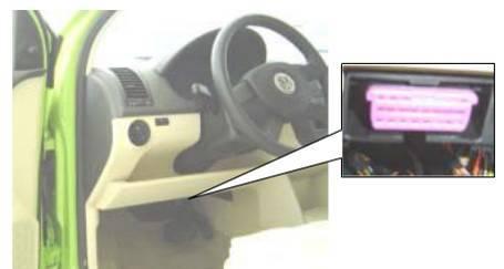
27 *BMW 735I: the OBD plug is in the right hands side of the engine bay, use BMW-20 connector. *VW Passat B5: the OBD plug is behind the gearlever and beside the parking brake lever. Lift the cover to access it. Use SMART OBDII-16 connector. 2. Location Diagram of Vehicle Diagnostic Link Connectors Location diagram of pick-up truck diagnostic link connectors: Location diagram of utility vehicles diagnostic link connectors: 27
28 Link diagram of small car diagnostic link connectors: NOTE: Each vehicle manufacturer may use additional pins to diagnose a variety of systems. Not every manufacturer uses the same standard. The function on a certain pin will vary from manufacturer to manufacturer. Verify with the manufacturer. 3. Diagnostic Link Connectors Terminal Definition and Communication Protocols 3.1. Standard OBDII Diagnostic Link Connector: Pin Definition (Reference material) Various pin definitions as follows: 1. Manufacturer definition 2. SAE J1850 bus positive 3. Manufacturer definition 4. Bodywork site 5. Signal site 6. ISO defined CAN high 7. ISO9141 and ISO14230 defined K line 8. Manufacturer definition 9. Manufacturer definition 10. SAE J1850 bus negative 28
29 System 11. Manufacturer definition 12. Manufacturer definition 13. ISO defined CAN low 14. ISO9141 and ISO14230 defined L line 15. Permanent positive voltage [1] 1, 3, 8, 9, 11, 12 and 13 are defined by manufacturer. [2] 2, 6, 7, 10, 14 and 15 are used for diagnostic communication. Unused definitions can be defined by manufacturers. 29
Declaration. Xtool X100 PAD2 User Manual Instructions
 Declaration 1. This manual is designed for the usage of X100 PAD2, applying to X100 PAD2 smart automotive diagnosis platform. No part of this manual can be reproduced, stored in a retrieval system or transmitted,
Declaration X-100 PAD
 Declaration 1. This manual is designed for the usage of, applying to X-100 PAD automotive diagnosis platform. No part of this manual can be reproduced, stored in a retrieval system or transmitted, in any
Precautions. sure the diagnostic socket on your vehicle export 11V~36V voltage. HD The HD900 work in 11V~36V voltage, please make
 Declaration HD900 1. This manual is designed for the usage of HD900. No part of this manual can be reproduced, stored in a retrieval system or transmitted, in any form or by any means (electronic, mechanical,
V30 Diagnostic Computer
 V30 Diagnostic Computer USER MANUAL Version 1.65 Copyright 2009 by Tech. Inc., an SPX Brand V30 instructions Please read this user manual carefully before using the scanner. The current user manual is
D730 User Manual instructions. D730 Diagnostic Computer main unit maintenance: Operation Instructions
 D730 User Manual instructions User Manual Please read this user manual carefully before using the scanner. The current user manual is based on the current features and functions available. Any new added
V30 Diagnostic Computer
 V30 Diagnostic Computer USER MANUAL Version 1.65 Copyright 2009 by Tech. Inc., an SPX Brand Statement Copyright 2008 by AUTOBOSS TECH. INC. (short for "AUTOBOSS"). All rights reserved. No part of this
LAUNCH. X-431 PRO3 Product Introduction
 X-431 PRO3 Product Introduction Content X-431 PRO3 Product Overview X-431 PRO3 Product Feature Product Parameters Compared with Similar Products Product Profile X-431 PRO3 is a brand new advanced automotive
iobd2 MFi BT VAG Adapter User Manual
 iobd2 MFi BT VAG Adapter User Manual VW, AUDI, SKODA, SEAT Preface Thank you for using this product. Please read instructions carefully before operating this unit. This manual guides the users how to operate
Audi 2014 Q5-A001 TUTORIAL.
 Audi 2014 Q5-A001 TUTORIAL www.aurodiag.com Trademarks Auro TM and OtoSys TM are trademarks of Shenzhen HC Tech CO., Ltd., registered in China, the United States and other countries. All other marks are
LAUNCH Create - Change
 Product Introduction X-431 PRO 3 Professional diagnostic solutions by mobile internet Introduction The X-431 PRO 3 is a new advanced automobile diagnostic solutions based on Android tablet. The new highlight
LAUNCH. X-431 PADII Product Introduction
 X-431 PADII Product Introduction Contents Product Introduction Machine Introduction Product Key Points Product Function Schematic Product Function Introduction Comparing X-431 PADII Parameters with Products
STATEMENT. (2) PS701 is just offered for the professional and technical personnel of vehicle maintenance
 PS701 is just offered for the professional and technical personnel of vehicle maintenance") STATEMENT (1) This manual is designed for the PS701 product, any company or individual are not permit to replicate and backup it in any form if they don't have the authority license from XTOOLTECH CO.,
STATEMENT (1) This manual is designed for the PS701 product, any company or individual are not permit to replicate and backup it in any form if they don't have the authority license from XTOOLTECH CO.,
EasyDiag Series. User s Manual (V ) Issued Date:
 Issued Date:") EasyDiag Series User s Manual (V1.00.001) Issued Date: 2014-08-15 Note: This user s manual applies to EasyDiag Series (EasyDiag and EasyDiag Plus) and is subject to change without prior written notice.
EasyDiag Series User s Manual (V1.00.001) Issued Date: 2014-08-15 Note: This user s manual applies to EasyDiag Series (EasyDiag and EasyDiag Plus) and is subject to change without prior written notice.
LAUNCH Create - Change
 Product Introduction X-431 PRO 3 Professional diagnostic solutions by mobile internet LAUNCH Introduction The LAUNCH X-431 PRO 3 is a new advanced automobile diagnostic solutions based on Android tablet.
FORD KM Tool (CAN BUS) User Manual
 User Manual") FORD KM Tool (CAN BUS) User Manual X-Horse Electronics Co., Ltd. Table of Contents 1. Safety Precautions and Warnings... 3 2. General Information... 4 3. Hardware Overview... 5 3.1. Tool Description...
FORD KM Tool (CAN BUS) User Manual X-Horse Electronics Co., Ltd. Table of Contents 1. Safety Precautions and Warnings... 3 2. General Information... 4 3. Hardware Overview... 5 3.1. Tool Description...
Used Delightedly, User-Friendly MARUTI,MAZDA,MITSUBISHI,NISSAN,SUBARU,SUZUKI,TOYOTA, TATA, CHRYSLER, 8
 Shor tcut keys Including CR501/601/611/801/811/821/910/920/981 DTC One-click Reading DTCs ER One-click Clearing DTCs I/M One-click Reading IM Readiness Statu? Tips and Help Car Model Suppor ting (46) Automotive
IMPORTANT NOTICES... 3 SAFETY PRECAUTIONS... 4
 CONTENTS IMPORTANT NOTICES........................................ 3 SAFETY PRECAUTIONS....................................... 4 Introduction...........................................5 Datastream............................................6
X-431 Volkswagen Diagnosis. Table of Contents INTRODUCTION...1
 Table of Contents INTRODUCTION...1 FEATURES...1 Advanced...1 Open...1 Integrative...1 Flexible...1 HARDWARE CONFIGURATION...2 PORTS AND INDICATORS...3 PRINTER OPERATION...4 Mounting Paper...4 Printing
V
 V1.00.000 2013-06-20 All rights reserved! No part of this publication may be reproduced, stored in a retrieval system or transmitted, in any form or by any means of electronic, mechanical, photocopying
Notes U695. (1) Vehicle power supply must meet the normal operating voltage, such as
 Vehicle power supply must meet the normal operating voltage, such as") STATEMENT (1) This manual is designed for the U695 product, any company or individual are not permit to replicate and backup it in any form if they don't have the authority license from UIFTECH CO., LTD
STATEMENT (1) This manual is designed for the U695 product, any company or individual are not permit to replicate and backup it in any form if they don't have the authority license from UIFTECH CO., LTD
Disclaimer. Safety Precautions and Warnings. icarsoft English User s Manual
 2015-02-06 V1.00.00 Note: This manual applies to icarsoft 2nd generation serial products and CR Plus and is subject to change without prior written notice. In addition, all instructions and illustrations
Table of Contents 1. Safety Precautions and Warnings General Information Hardware Overview Tool Description Specif
 Table of Contents 1. Safety Precautions and Warnings... 3 2. General Information... 4 3. Hardware Overview... 5 3.1. Tool Description... 5 3.2. Specifications... 6 3.3. System Requirements... 7 4. Software
EasyDiag User s Manual. Issued:
 Issued:2013-11-11 Precautions on operating vehicle s ECU Do not disconnect the vehicle inner consume when the ignition switch is on, so as to avoid the sensors or the ECU damage. Do not place the magnetic
General Notice Introduction Functional Description Product Troubleshooting Driver Setup...
 Table of Contents General Notice... 1 Introduction... 2 Functional Description... 4 Product Troubleshooting... 7 Driver Setup... 8 Firmware Update... 10 Warranty and Service... 12 General Notice The Bluetooth
CAR SCANNER AND DIAGNOSTIC TOOL
 SNo Product Picture Qt Price AUTO- PRO ENGINE SCANNER (Guaranteed fastest update, a promise backed up by our experience in garage equipment). Super scanner Auto Pro is the latest automotive diagnostic
MVCI Cable User Manual X-Horse Electronics Co., Ltd.
 MVCI Cable User Manual X-Horse Electronics Co., Ltd. Table of Contents 1. Safety Precautions and Warnings... 3 2. General Information... 4 3. MVCI Overview... 5 3.1. Tool Description... 5 3.2. Specifications...
Description: Autologic Assist plus:
 Autologic Assist plus: Description: AssistPlus is the central hub of any modern workshop. Four times faster and more feature rich than the Blue Box, AssistPlus is a platform that expands as new functions
V
 V1.00.000 2011-08-06 All rights reserved! No part of this publication may be reproduced, stored in a retrieval system or transmitted, in any form or by any means of electronic, mechanical, photocopying
SAFETY PRECAUTIONS AND WARNINGS...
 Table of Contents 1. SAFETY PRECAUTIONS AND WARNINGS... 1 2. GENERAL INFORMATION... 2 2.1 ON-BOARD DIAGNOSTICS (OBD) II... 2 2.2 DIAGNOSTIC TROUBLE CODES (DTCS)... 2 2.3 LOCATION OF THE DATA LINK CONNECTOR
MOTO M -1 Use s r manu n al
 MOTO-1 User manual Operate introduction Dear user Your purchased tool is belong to the MOTO-1 series, it cover all our technology and experience in many years. The tool will be a very useful work partner
USER GUIDE. incardoc Android
 USER GUIDE incardoc Android OVERVIEW Use Smartphone for Quick View of the Car and Engine Main Parameters: Read real-time parameters: speed, rotation, timings, economy Read diagnostic trouble codes Clean
USING SCAN TOOL MEMORY
 Table of Contents SAFETY PRECAUTIONS SAFETY FIRST!... 1 SCAN TOOL CONTROLS CONTROLS AND INDICATORS... 3 DISPLAY FUNCTIONS... 4 BATTERY REPLACEMENT... 6 USING THE SCAN TOOL CODE RETRIEVAL PROCEDURE... 7
CNC-601A / -602A / -801A
 CNC-601A / -602A / -801A Injector cleaner & tester CNC-601A / -602A / -801A injector cleaner and tester makes full use of both ultrasonic cleaning and microcomputer controlling technology. Features Manufactured
COPYRIGHT NOTICE. Visit our website at: For Technical Assistance, send us at
 COPYRIGHT NOTICE Visit our website at: www.idutex.com For Technical Assistance, send us email at support@idutex.com 1 OBDII/EOBD PLUS Code Reader USER MANUAL 2 General Notice For your own safety and the
E8431 First Edition Model: T00CP
 Quick Start Guide E8431 First Edition Model: T00CP Copyright 2013 ASUSTeK COMPUTER INC. All Rights Reserved. No part of this manual, including the products and software described in it, may be reproduced,
SKP1000 tablet key programmer User manual
 SKP1000 tablet key programmer User manual Content 1. Product description... 1 1.1 Supported protocol... 3 1.2 Package Includes... 3 2. Function Menu Instruction... 4 2.10 Main menu basic functions... 4
Troubleshooter Quick Reference Guide
 Troubleshooter Quick Reference Guide March 2008 EAZ0025B29B Rev. C Trademarks Acknowledgement Snap-on, Scanner, and Fast-Track are trademarks of Snap-on Incorporated. All other marks are trademarks of
RETUFU H O MAIN 2008 GM Service and Parts Operations
 RETUFU H O MAIN MENIJ u @ 2008 GM Service and Parts Operations I. Introduction MDI User s Guide The Multiple Diagnostic Interface User s Guide provides an overview of the MDI tool. Everything contained
User manual TaBleT l7 3G
 User manual TABLET L7 3G Congratulations on the purchase of your Tesla tablet! 1. To use your Tablet safely and correctly, please read the instructions in this manual carefully before use. 2. Our company
Precision Tec Diagnostics PO Box 2431 Cartersville, GA
 Precision Tec Diagnostics PO Box 2431 Cartersville, GA 30120 e-mail: toolsupport@precisiontec.us info@precisiontec.us iscan3 PLATINUM provides a powerful tool for vehicle diagnostics. The intuitive user
OBDII J1708/J1587 Simulator
 1 Features: Support the total 8 protocols., Customer can choose any 2 protocols or any 5 protocols or all 8 protocols in different cost 1. ISO14230-4 (KWP2000) Fast Init 2. ISO14230-4 (KWP2000) Baud 5
PLEASE READ BEFORE OPERATING THIS EQUIPMENT.
 PLEASE READ BEFORE OPERATING THIS EQUIPMENT. HALO BOLT ACDC WIRELESS Thank you for choosing HALO! Powerful, compact and easy to use, the HALO BOLT ACDC WIRELESS can safely jump start your car or charge
Release Date: September 4, 2014
 MV1DU User s Guide Release Date: September 4, 2014 Use of the MV1DU Diagnostic System requires an active license agreement or MV-1 Dealer Agreement. For information on obtaining a license, please email
Delphi Diagnostics DS100E user manual version 7.0 Software Version
 Delphi Diagnostics DS100E user manual version 7.0 Software Version 1.17.0 1. Summary 1 Summary 2 Copyright/Trademark 3 About the DS100E 4 Main functions of the DS100E tool 5 OBD 6 EOBD 7 Configuration
WayteQ GPS Navigation X960BT User Manual. English Version
 WayteQ GPS Navigation X960BT User Manual English Version Thanks for using WAYTEQ products! WAYTEQ reserves the rights of final interpretation of the manual. The product is subject to change without any
SAFETY PRECAUTIONS AND WARNINGS...
 Table of Contents 1. SAFETY PRECAUTIONS AND WARNINGS... 1 2. TOOL INFORMATION... 2 2.1 TOOL DESCRIPTION... 2 2.2 SPECIFICATIONS... 4 2.3 ACCESSORIES INCLUDED... 4 2.4 ICONS... 4 2.5 KEYBOARD... 5 2.6 BATTERY
Dodge Cummins Package Contents
 2010 2012 Dodge Cummins EFILive Instructions ------------------------------------------------------------------ Package Contents AutoCal W/ 1 Pre-loaded Tune AutoCal Cables USB & OBDII Koozi PPEI Flash
ZTE MOBILE HOTSPOT QUICK START GUIDE
 ZTE MOBILE HOTSPOT QUICK START GUIDE INTRODUCTION Thank you for choosing Consumer Cellular! We know you re excited to use your new ZTE Mobile Hotspot, and this short guide will help you get familiar with
360 VR Camera FOR USB-C MOBILE DEVICES
 360 VR Camera FOR USB-C MOBILE DEVICES TABLE OF CONTENTS Warnings and Cautions...1 Location of Parts... 2 Installing the Opai360 App.... 3 Connecting the Camera To Your Phone... 4 Taking Photos and Recording
CAM-KIT6. User Manual. Connects2Vision. Mirror with DVR & Rear Camera PRODUCT FEATURES:
 User Manual CAM-KIT6 Mirror with DVR & Rear Camera PRODUCT FEATURES: Display: 5 inch Speaker: Built in MIC: Built in Mini USB: 5V 2A Micro SD Card Support: 32G max (not supplied) Rear Camera Input: 2.5mm
Lenovo S60-a. Quick Start Guide. Read this guide carefully before using your smartphone.
 Lenovo S60-a Quick Start Guide Read this guide carefully before using your smartphone. First glance 1 2 3 4 11 12 13 5 6 14 15 7 10 9 8 16 17 13 1 Headset connector 2 Light/Proximity sensor 3 Receiver
SAFETY PRECAUTIONS AND WARNINGS...
 Table of Contents 1. SAFETY PRECAUTIONS AND WARNINGS... 1 2. GENERAL INFORMATION... 2 2.1 ON-BOARD DIAGNOSTICS (OBD) II... 2 2.1.1 DIAGNOSTIC TROUBLE CODES (DTCS)... 2 2.1.2 OBDII MODES OF OPERATION...
SAFETY PRECAUTIONS AND WARNINGS...
 Table of Contents 1. SAFETY PRECAUTIONS AND WARNINGS... 1 2. GENERAL INFORMATION... 2 2.1 ON-BOARD DIAGNOSTICS (OBD) II... 2 2.1.1 DIAGNOSTIC TROUBLE CODES (DTCS)... 2 2.1.2 OBDII MODES OF OPERATION...
SAFETY PRECAUTIONS AND WARNINGS...
 Table of Contents 1. SAFETY PRECAUTIONS AND WARNINGS... 1 2. TOOL INFORMATION... 2 2.1 TOOL DESCRIPTION... 2 2.2 SPECIFICATIONS... 3 2.3 ACCESSORIES INCLUDED... 3 2.4 ICONS... 4 2.5 KEYBOARD... 4 2.6 BATTERY
1. Notes. 2. Accessories. 3. Main Functions
 Contents 1. Notes... 2 2. Accessories... 2 3. Main Functions... 2 4. Appearance And Buttons... 3 5. MID Hardware Parameters... 4 6. MID Use And Preparation... 4 7. Keys Functions... 4 8. Start-up And Shutdown...
Either witech OR StarMOBILE DESKTOP CLIENT can be used to perform this bulletin. FLASH FILES FOR THIS BULLETIN ARE AVAILABLE VIA THE INTERNET.
 NUMBER: 18-020-10 GROUP: Vehicle Performance DATE: June 10, 2010 This bulletin is supplied as technical information only and is not an authorization for repair. No part of this publication may be reproduced,
BEAT 2.0 USER MANUAL
 BEAT 2.0 USER MANUAL FCC ID: 2ADLJBEAT20 The device complies with part 15 of the FCC Rules. Operation is subject to the following two conditions: (1) This device may not cause harmful interference, and
Version: V Revised date:
 Version: V1.00.000 Revised date: 04-10-2014 Copyright Information Copyright 2013 by LAUNCH TECH. CO., LTD. All rights reserved. No part of this publication may be reproduced, stored in a retrieval system,
OBD-II Engine Code Reader with Bluetooth Technology
 User Manual OBD-II Engine Code Reader with Bluetooth Technology PP-2145 Specifications: Working environment temperature: -40 C ~ 85 C Voltage: 9-16VDC Working current: 45mA Standby current: < 40mA Wireless
Quick Start Guide. SupraPad i1000qw. 10.1" Windows Tablet
 SupraPad i1000qw Quick Start Guide NOTE: For Spanish users, please go to Control Panel", then go to Clock, Language, and Region", then go to Language to change from English to Spanish Language OSD. 10.1"
Startup Guide C01
 Startup Guide 4012988-00 C01 Startup Guide English Where to Find Information........................ 2 Safety Instructions.............................. 4 Important Safety Instructions...........................
MP3 Speaker USER GUIDE
 MP3 Speaker USER GUIDE Jazwares, Inc. 2012 CONTENTS Please read the instructions along with the Speaker carefully before you use it, so that you can operate it conveniently. WELCOME, Warnings & Safety
HuddlePod Air DUO Dual Wireless Audio Pods Installation and Operation Manual
 HuddlePod Air DUO Dual Wireless Audio Pods Installation and Operation Manual Please visit www.huddlecamhd.com/ for the most up to date version of this manual Precautions Safety Tips Please be aware any
X725 USB DAC & AMP. User s Manual
 X725 USB DAC & AMP User s Manual TVLogic Co., Ltd. owns all intellectual property rights to the technical information detailed in this manual. This manual may only be used by and distributed to authorized
NL5 USER MANUAL ENGLISH
 NL5 USER MANUAL ENGLISH March 2017 CONTENTS BEFORE YOU START...5 Make sure you have everything...5 Familiarize yourself with the computer...6 OPENING THE DISPLAY PANEL...6 FRONT OVERVIEW...7 LEFT SIDE
SAFETY PRECAUTIONS AND WARNINGS...
 Table of Contents 1. SAFETY PRECAUTIONS AND WARNINGS... 1 2. GENERAL INFORMATION... 2 2.1 ON-BOARD DIAGNOSTICS (OBD) II... 2 2.2 DIAGNOSTIC TROUBLE CODES (DTCS)... 2 2.3 LOCATION OF THE DATA LINK CONNECTOR
Quick Start Guide. Thank you for your choosing the new Tablet PC.This guide serves to enable users to get to
 Quick Start Guide Introduction Thank you for your choosing the new Tablet PC.This guide serves to enable users to get to know and familiar with our product as soon as possible. Here we have made a brief
ZTE MOBILE HOTSPOT QUICK START GUIDE
 ZTE MOBILE HOTSPOT QUICK START GUIDE INTRODUCTION Thank you for choosing Consumer Cellular! We know you re excited to use your new ZTE Mobile Hotspot, and this short guide will help you get familiar with
UNIDEN AUTOMOTIVE VIDEO RECORDER CAM 500
 UNIDEN AUTOMOTIVE VIDEO RECORDER CAM 500 IMPORTANT SAFETY INSTRUCTIONS This product is not waterproof. Do not expose it to rain or moisture. This product is intended for use in a motor vehicle. Don t install
User Guide. Model: ELT0702
 User Guide Model: ELT0702 Welcome! Thank you for purchasing your new Epik Learning Tab Jr. This User Guide will provide step-by-step instructions to help you learn to use your new device. After opening
Disclaimer of Warranties and Limitation of Liabilities
 Trademarks Autel, MaxiSys, MaxiDAS, MaxiScan, MaxiTPMS, MaxiRecorder, and MaxiCheck are trademarks of Autel Intelligent Technology Corp., Ltd., registered in China, the United States and other countries.
Carmanscan AT User Guide
 Carmanscan AT User Guide Ver. 100501A Safety Cautions This information is to protect your safety and prevent property damage. Make sure to read it thoroughly before use. 1 Table of Contents Cautions in
User Guide. Subaru Turbo (North American Models)
") User Guide Subaru Turbo (North American Models) Page 2 Table of Contents Product Introduction 4 Supported Vehicle List 4 In-Box Contents 5 What Is A Map? 7 AccessPORT Installation 8 Pre-Installation 8
User Guide Subaru Turbo (North American Models) Page 2 Table of Contents Product Introduction 4 Supported Vehicle List 4 In-Box Contents 5 What Is A Map? 7 AccessPORT Installation 8 Pre-Installation 8
HD829THD USER MANUAL
 HD829THD USER MANUAL Thank you for buying this XTRONS product. Please read through these instructions so you will know how to operate this product properly. After you have finished reading the instructions,
OBD Auto Doctor. User Manual for ios (iphone and ipad) Copyright 2018 Creosys Ltd
 Copyright 2018 Creosys Ltd") OBD Auto Doctor User Manual for ios (iphone and ipad) Copyright 2018 Creosys Ltd User Manual for ios (iphone and ipad) 1. Introduction 1.1 Platform and Hardware Requirements 1.2 Supported Adapters 1.3
OBD Auto Doctor User Manual for ios (iphone and ipad) Copyright 2018 Creosys Ltd User Manual for ios (iphone and ipad) 1. Introduction 1.1 Platform and Hardware Requirements 1.2 Supported Adapters 1.3
Quick Start Guide D U.S Service Hotline : More support at
 TM Quick Start Guide D-7 U.S Service Hotline : -888-707-655 More support at www.dpad.info Overview Touch Screen App Menu 4 5 4 5 6 Camera Power Key Earphone Jack Mini USB Port 7 6 7 8 9 8 7 Power DC Input
User Guide Models: ELT0801H and ELT0703H
 User Guide Models: ELT0801H and ELT0703H Designed by the EPIK Learning Company California, USA Welcome! Thank you for purchasing your new HIGHQ Learning Tab. This User Guide will provide step-by-step instructions
Table of Contents SAFETY PRECAUTIONS AND WARNINGS... 1 GENERAL INFORMATION ON-BOARD DIAGNOSTICS (OBD) II DIAGNOSTIC TROUBLE CODES
 II DIAGNOSTIC TROUBLE CODES") Table of Contents 1. 2. SAFETY PRECAUTIONS AND WARNINGS... 1 GENERAL INFORMATION... 2 2.1 ON-BOARD DIAGNOSTICS (OBD) II... 2 2.2 DIAGNOSTIC TROUBLE CODES (DTCS)... 2 2.3 LOCATION OF THE DATA LINK CONNECTOR
Table of Contents 1. 2. SAFETY PRECAUTIONS AND WARNINGS... 1 GENERAL INFORMATION... 2 2.1 ON-BOARD DIAGNOSTICS (OBD) II... 2 2.2 DIAGNOSTIC TROUBLE CODES (DTCS)... 2 2.3 LOCATION OF THE DATA LINK CONNECTOR
PLDANDHR1056KT. Android Touchscreen Tablet Entertainment Display Bundle
 PLDANDHR1056KT Android Touchscreen Tablet Entertainment Display Bundle Dual Vehicle Headrest Mount Multimedia Systems with Bluetooth, Wi-Fi & App Download (10.5 -inch) FRONT PANEL MULTIMEDIA PLAYER 1.
OBDII Code Scanner ( ) CAN+VW/AUDI. Manual
 CAN+VW/AUDI. Manual") OBDII Code Scanner ( ) CAN+VW/AUDI Manual Table of Contents 1. Safety Precautions and Warnings...2 2. Product Information 2.1 Tool Description...3 2.2 Specifications...4 2.3 Accessories Included...4 2.4
OBDII Code Scanner ( ) CAN+VW/AUDI Manual Table of Contents 1. Safety Precautions and Warnings...2 2. Product Information 2.1 Tool Description...3 2.2 Specifications...4 2.3 Accessories Included...4 2.4
Hanatech Co., Ltd. I. Diagnostic Trouble Code
 Hanatech Co., Ltd. Chapter 4 ULTRASCAN P1 Functions The functions you can choose when all the test vehicle details are selected properly are explained in this chapter of the manual. The actual list of
Audi, Seat, Skoda and Volkswagen
 Seat, Skoda and Volkswagen Audi, Seat, Skoda and Volkswagen ECU Version (VAG Mode 1) Selecting 'ECU Version' displays the following data for the selected control module: Part Number System Name Version
Table of Contents 1. SAFETY PRECAUTIONS AND WARNINGS GENERAL INFORMATION ON-BOARD DIAGNOSTICS (OBD) II DIAGNOSTIC TROUBLE
 II DIAGNOSTIC TROUBLE") Table of Contents 1. SAFETY PRECAUTIONS AND WARNINGS... 1 2. GENERAL INFORMATION... 2 2.1 ON-BOARD DIAGNOSTICS (OBD) II... 2 2.2 DIAGNOSTIC TROUBLE CODES (DTCS)... 2 2.3 LOCATION OF THE DATA LINK CONNECTOR
Table of Contents 1. SAFETY PRECAUTIONS AND WARNINGS... 1 2. GENERAL INFORMATION... 2 2.1 ON-BOARD DIAGNOSTICS (OBD) II... 2 2.2 DIAGNOSTIC TROUBLE CODES (DTCS)... 2 2.3 LOCATION OF THE DATA LINK CONNECTOR
MOBILE SAFETY DVR1543K. CLIP ON REARVIEW MIRROR KIT with 4.3-INCH LCD MONITOR FRONT & REAR CAR CAMCORDER with DUAL MOUNTING REVERSING CAMERA
 MOBILE SAFETY DVR1543K REARVIEW MIRROR CAR DRIVING RECORDER KIT CLIP ON REARVIEW MIRROR KIT with 4.3-INCH LCD MONITOR FRONT & REAR CAR CAMCORDER with DUAL MOUNTING REVERSING CAMERA 3.0 MEGA PIXEL CAMERA
Disclaimer of Warranties and Limitation of Liabilities
 Trademarks Autel, MaxiSys, MaxiDAS, MaxiScan, MaxiCheck, MaxiRecorder, and MaxiCheck are trademarks of Autel Intelligent Technology Corp., Ltd., registered in China, the United States and other countries.
ZTE CruiseConnect Quick Start Guide
 ZTE CruiseConnect Quick Start Guide Application Powered by Modus 1 Getting to Know Your OBD II Device Appearance The following figure is for your reference only. 1. Reset hole 2. micro-sim card slot 3.
ZOTAC VR GO. User s Manual
 User s Manual ZOTAC VR GO No part of this manual, including the products and software described in it, may be reproduced, transmitted, transcribed, stored in a retrieval system, or translated into any
B&W RearView Camera Installation & Operation
 B&W RearView Camera Installation & Operation CA52 (Camera) FOR MORE INFORMATION WWW.STRATEGICVISTA.COM BEFORE OPERATING THIS SYSTEM, PLEASE READ THIS MANUAL THOROUGHLY AND RETAIN IT FOR FUTURE REFERENCE
SAFETY PRECAUTIONS AND WARNINGS...
 Table of Contents 1. SAFETY PRECAUTIONS AND WARNINGS... 1 2. GENERAL INFORMATION... 2 2.1 ON-BOARD DIAGNOSTICS (OBD) II... 2 2.2 DIAGNOSTIC TROUBLE CODES (DTCS)... 2 2.3 LOCATION OF THE DATA LINK CONNECTOR
12/2013. Installation Guide & User Manual
 12/2013 Installation Guide & User Manual ABOUT THIS MANUAL This manual has been written to help you understand all the functions and capabilities of the Yamaha Snowmobile Diagnostic Tool in order to gain
Model: CAM430MV Wired Multi-View Camera with License Plate / Rear Surface Mount Installation Manual Features
 Model: CAM430MV Wired Multi-View Camera with License Plate / Rear Surface Mount Installation Manual Features Fully Adjustable, Multiple Viewing Angle Smart Camera. High Resolution, 1/2 CMOS Color Camera
Manual OBDII Code Scanner ( ) CAN+VW/AUDI
 CAN+VW/AUDI") Any questions please don't hesitate to contact us. sales02@cardiag.co.uk Yahoo:cardiag.service@yahoo.com OBDII Code Scanner ( ) CAN+VW/AUDI Manual Table of Contents 1. Safety Precautions and Warnings...2
Any questions please don't hesitate to contact us. sales02@cardiag.co.uk Yahoo:cardiag.service@yahoo.com OBDII Code Scanner ( ) CAN+VW/AUDI Manual Table of Contents 1. Safety Precautions and Warnings...2
TECHNICAL SERVICE BULLETIN
 GROUP ELE NUMBER MODEL 2014MY Soul (PS) DATE 058 March 2014 TECHNICAL SERVICE BULLETIN SERVICE ACTION: BCM UPGRADE - IPM LOGIC This bulletin provides information related to the reprogramming of the Body
Network Camera. Quick Guide DC-B1203X. Powered by
 Network Camera Quick Guide DC-B1203X Powered by Safety Precautions English WARNING RISK OF ELECTRIC SHOCK DO NOT OPEN WARNING: TO REDUCE THE RISK OF ELECTRIC SHOCK, DO NOT REMOVE COVER (OR BACK). NO USER-SERVICEABLE
Quick Start Guide. SupraPad i800qw. 8" SupraPad
 SupraPad i800qw Quick Start Guide NOTE: For Spanish users, please go to Control Panel", then go to Clock, Language, and Region", then go to Language to change from English to Spanish Language OSD. 8" SupraPad
Diesel Particulate Filter DPF Service Regeneration Table 1: Service Regeneration Successful Table 2: Service Regeneration Unsuccessful
 Service Information 2007 Chevrolet Silverado - 4WD [1GCHK23657F529413] Sierra, Silverado VIN C/K Service Manual Engine Engine Controls and Fuel - 6.6L LMM Diagnostic Information and Procedures Document
EngineCheck. User manual Version January Gendan Limited
 User manual Version 3.1 January 2013 sales@enginecheck.co.uk www.enginecheck.co.uk 2013 Gendan Limited Table of contents Installation 3 Activation 3 Using 4 Connecting to a car 5 Connection problems 5
Quick Start Guide Notion Ink Design Labs Pvt. Ltd. 1
 Quick Start Guide 2014 Notion Ink Design Labs Pvt. Ltd. 1 2014 Notion Ink Design Labs Pvt. Ltd. 2 Contents 1. Caring for your device 2. Travelling with your device 3. Device layout 4. Keyboard case layout
Operating Instructions
 9000 Operating Instructions Contents Introduction 1 Operating Instructions 2-5 Demonstrations 6-8 Storing/Handling/Cleaning 9 Safety Precautions 9-10 Specifications 10 FCC Compliance Statement 11-12 Limited
MF920V Quick Start Guide
 MF920V Quick Start Guide 1 Getting to Know Your Device Appearance The following figure is for your reference only. 1. *External antenna connectors (not all the devices support) 2. Charging/micro-USB jack