was designed and is being produced by Gravitech.
|
|
|
- Duane Hall
- 5 years ago
- Views:
Transcription
1
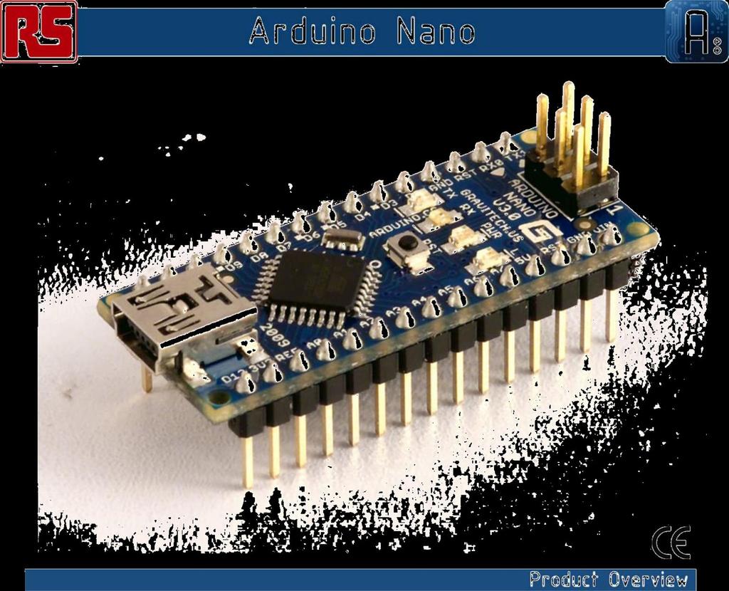
2 The Arduino Nano is a small, complete, and breadboard-friendly board based on the ATmega328 (Arduino Nano 3.0) or ATmega168 (Arduino Nano 2.x). It has more or less the same functionality of the Arduino Duemilanove, but in a different package. It lacks only a DC power jack, and works with a Mini-B USB cable instead of a standard one. The Nano was designed and is being produced by Gravitech.
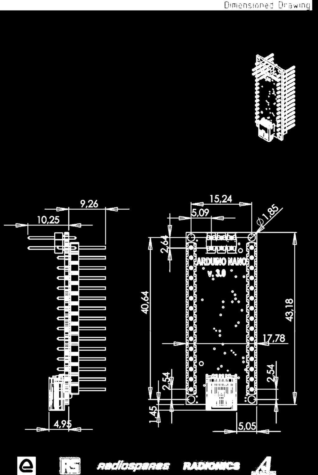
3 Arduino Nano 3.0 (ATmega328): schematic, Eagle files. Arduino Nano 2.3 (ATmega168): manual (pdf), Eagle files. Note: since the free version of Eagle does not handle more than 2 layers, and this version of the Nano is 4 layers, it is published here unrouted, so users can open and use it in the free version of Eagle. Microcontroller Atmel ATmega168 or ATmega328 Operating Voltage (logic level) 5 V Input Voltage (recommende d) Input Voltage (limits) Digital I/O Pins Analog Input Pins DC Current per I/O Pin Flash Memory SRAM EEPROM Clock Speed 7-12 V 6-20 V 14 (of which 6 provide PWM output) 8 40 ma 16 KB (ATmega168) or 32 KB (ATmega328) of which 2 KB used by bootloader 1 KB (ATmega168) or 2 KB (ATmega328) 512 bytes (ATmega168) or 1 KB (ATmega328) 16 MHz 0.73" x 1.70" Dimensions

4 The Arduino Nano can be powered via the Mini -B USB connection, 6-20V unregulated external power supply (pin 30), or 5V regulated external power supply (pin 27). The power source is automatically selected to the highest voltage source. The FTDI FT232RL chip on the Nano is only powered if the board is being powered over USB. As a result, when running on external (non-usb) power, the 3.3V output (which is supplied by the FTDI chip) is not available and the RX and TX LEDs will flicker if digital pins 0 or 1 are high. The ATmega168 has 16 KB of flash memory for storing code (of which 2 KB is used for the bootloader); the ATmega328 has 32 KB, (also with 2 KB used for the bootloader). The ATmega168 has 1 KB of SRAM and 512 bytes of EEPROM (which can be read and written with the EEPROM library); the ATmega328 has 2 KB of SRAM and 1 KB of EEPROM.
5 Each of the 14 digital pins on the Nano can be used as an input or output, using pinmode(), digitalwrite(), and digitalread() functions. They operate at 5 volts. Each pin can provide or receive a maximum of 40 ma and has an internal pull-up resistor (disconnected by default) of kohms. In addition, some pins have specialized functions: Serial: 0 (RX) and 1 (TX). Used to receive (RX) and transmit (TX) TTL serial data. These pins are connected to the corresponding pins of the FTDI USB-to-TTL Serial chip. External Interrupts: 2 and 3. These pins can be configured to trigger an interrupt on a low value, a rising or falling edge, or a change in value. See the attachinterrupt() function for details. PWM: 3, 5, 6, 9, 10, and 11. Provide 8-bit PWM output with the analogwrite() function. SPI: 10 (SS), 11 (MOSI), 12 (MISO), 13 (SCK). These pins support SPI communication, which, although provided by the underlying hardware, is not currently included in the Arduino language. LED: 13. There is a built-in LED connected to digital pin 13. When the pin is HIGH value, the LED is on, when the pin is LOW, it's off. The Nano has 8 analog inputs, each of which provide 10 bits of resolution (i.e different values). By default they measure from ground to 5 volts, though is it possible to change the upper end of their range using the analogreference() function. Additionally, some pins have specialized functionality: I 2 C: 4 (SDA) and 5 (SCL). Support I 2 C (TWI) communication using the Wire library (documentation on the Wiring website). There are a couple of other pins on the board: AREF. Reference voltage for the analog inputs. Used with analogreference(). Reset. Bring this line LOW to reset the microcontroller. Typically used to add a reset button to shields which block the one on the board. See also the mapping between Arduino pins and ATmega168 ports.
6 The Arduino Nano has a number of facilities for communicating with a computer, another Arduino, or other microcontrollers. The ATmega168 and ATmega328 provide UART TTL (5V) serial communication, which is available on digital pins 0 (RX) and 1 (TX). An FTDI FT232RL on the board channels this serial communication over USB and the FTDI drivers (included with the Arduino software) provide a virtual com port to software on the computer. The Arduino software includes a serial monitor which allows simple textual data to be sent to and from the Arduino board. The RX and TX LEDs on the board will flash when data is being transmitted via the FTDI chip and USB connection to the computer (but not for serial communication on pins 0 and 1). A SoftwareSerial library allows for serial communication on any of the Nano's digital pins. The ATmega168 and ATmega328 also support I2C (TWI) and SPI communication. The Arduino software includes a Wire library to simplify use of the I2C bus; see the documentation for details. To use the SPI communication, please see the ATmega168 or ATmega328 datasheet. The Arduino Nano can be programmed with the Arduino software (download). Select "Arduino Diecimila, Duemilanove, or Nano w/ ATmega168" or "Arduino Duemilanove or Nano w/ ATmega328" from the Tools > Board menu (according to the microcontroller on your board). For details, see the reference and tutorials. The ATmega168 or ATmega328 on the Arduino Nano comes preburned with a bootloader that allows you to upload new code to it without the use of an external hardware programmer. It communicates using the original STK500 protocol (reference, C header files). You can also bypass the bootloader and program the microcontroller through the ICSP (In- Circuit Serial Programming) header; see these instructions for details. Rather then requiring a physical press of the reset button before an upload, the Arduino Nano is designed in a way that allows it to be reset by software running on a connected computer. One of the hardware flow control lines (DTR) of the FT232RL is connected to the reset line of the ATmega168 or ATmega328 via a 100 nanofarad capacitor. When this line is asserted (taken low), the reset line drops long enough to reset the chip. The Arduino software uses this capability to allow you to upload code by simply pressing the upload button in the Arduino environment. This means that the bootloader can have a shorter timeout, as the lowering of DTR can be wellcoordinated with the start of the upload. This setup has other implications. When the Nano is connected to either a computer running Mac OS X or Linux, it resets each time a connection is made to it from software (via USB). For the following half-second or so, the bootloader is running on the Nano. While it is programmed to ignore malformed data (i.e. anything besides an upload of new code), it will intercept the first few bytes of data sent to the board after a connection is opened. If a sketch running on the board
7 receives one-time configuration or other data when it first starts, make sure that the software with which it communicates waits a second after opening the connection and before sending this dat
 and the Arduino development environment (based on Processing).")
8 Arduino can sense the environment by receiving input from a variety of sensors and can affect its surroundings by controlling lights, motors, and other actuators. The microcontroller on the board is programmed using the Arduino programming language (based on Wiring) and the Arduino development environment (based on Processing). Arduino projects can be stand-alone or they can communicate with software on running on a computer (e.g. Flash, Processing, MaxMSP). Arduino is a cross -platoform program. You ll have to follow different instructions for your personal OS. Check on the Arduino site for the latest instructions. Once you have downloaded/unzipped the arduino IDE, you ll need to install the FTDI Drivers to let your PC talk to the board. First Plug the Arduino to your PC via USB cable. Now you re actually ready to burn your first program on the arduino board. To select blink led, the physical translation of the well known programming hello world, select File>Sketchbook> Arduino-0017>Examples> Digital>Blink Once you have your skecth you ll see something very close to the screenshot on the right. In Tools>Board select Arduino NANO and with the AtMEGA you re using (probably 328)

9 Now you have to go to Tools>SerialPort and select the right serial port, the one arduino is attached to.
10
11 1. Warranties 1.1 The producer warrants that its products will conform to the Specifications. This warranty lasts for one (1) years from the date of the sale. The producer shall not be liable for any defects that are caused by neglect, misuse or mistreatment by the Customer, including improper installation or testing, or for any products that have been altered or modified in any way by a Customer. Moreover, The producer shall not be liable for any defects that result from Customer's design, specifications or instructions for such products. Testing and other quality control techniques are used to the extent the producer deems necessary. 1.2 If any products fail to conform to the warranty set forth above, the producer's sole liability shall be to replace such products. The producer's liability shall be limited to products that are determined by the producer not to conform to such warranty. If the producer elects to replace such products, the producer shall have a reasonable time to replacements. Replaced products shall be warranted for a new full warranty period. 1.3 EXCEPT AS SET FORTH ABOVE, PRODUCTS ARE PROVIDED "AS IS" AND "WITH ALL FAULTS." THE PRODUCER DISCLAIMS ALL OTHER WARRANTIES, EXPRESS OR IMPLIED, REGARDING PRODUCTS, INCLUDING BUT NOT LIMITED TO, ANY IMPLIED WARRANTIES OF MERCHANTABILITY OR FITNESS FOR A PARTICULAR PURPOSE 1.4 Customer agrees that prior to using any systems that include the producer products, Customer will test such systems and the functionality of the products as used in such systems. The producer may provide technical, applications or design advice, quality characterization, reliability data or other services. Customer acknowledges and agrees that providing these services shall not expand or otherwise alter the producer's warranties, as set forth above, and no additional obligations or liabilities shall arise from the producer providing such services. 1.5 The Arduino products are not authorized for use in safety-critical applications where a failure of the product would reasonably be expected to cause severe personal injury or death. Safety-Critical Applications include, without limitation, life support devices and systems, equipment or systems for the operation of nuclear facilities and weapons systems. Arduino products are neither designed nor intended for use in military or aerospace applications or environments and for automotive applications or environment. Customer acknowledges and agrees that any such use of Arduino products which is solely at the Customer's risk, and that Customer is solely responsible for compliance with all legal and regulatory requirements in connection with such use. 1.6 Customer acknowledges and agrees that it is solely responsible for compliance with all legal, regulatory and safety-related requirements concerning its products and any use of Arduino products in Customer's applications, notwithstanding any applications-related information or support that may be provided by the producer. 2. Indemnification The Customer acknowledges and agrees to defend, indemnify and hold harmless the producer from and against any and all third-party losses, damages, liabilities and expenses it incurs to the extent directly caused by: (i) an actual breach by a Customer of the representation and warranties made under this terms and conditions or (ii) the gross negligence or willful misconduct by the Customer. 3. Consequential Damages Waiver In no event the producer shall be liable to the Customer or any third parties for any special, collateral, indirect, punitive, incidental, consequential or exemplary damages in connection with or arising out of the products provided hereunder, regardless of whether the producer has been advised of the possibility of such damages. This section will survive the termination of the warranty period. 4. Changes to specifications The producer may make changes to specifications and product descriptions at any time, without notice. The Customer must not rely on the absence or characteristics of any features or instructions marked "reserved" or "undefined." The producer reserves these for future definition and shall have no responsibility whatsoever for conflicts or incompatibilities arising from future changes to them. The product information on the Web Site or Materials is subject to change without notice. Do not finalize a design with this information.

 M-1715-1.5 (1) M-1719-1.5 (1) Holding torque oz-in 32 60 75 N-cm 23 42 53 Detent torque oz-in 1.7 2.1 3.5 N-cm 1.2 1.")
12 Quick Reference NEMA size phase stepper motor Notes and Warnings Installation, configuration and maintenance must be carried out by qualified tech-nicians only. You must have detailed information to be able to carry out this work. Unexpected dangers may be encountered when working with this product! Incorrect use may destroy this product and connected components! For more information, go to Specifications 1.5 Amp motors Single length Double length Triple length Part number M (1) M (1) M (1) Holding torque oz-in N-cm Detent torque oz-in N-cm Rotor inertia oz-in-sec kg-cm Weight oz grams Phase current amps Phase resistance ohms Phase inductance mh (1) Indicate S for single-shaft or D for double-shaft. Example M S Wiring and Connections Signals and wire colors Phase A Red Phase /A Blue Phase B Green Phase /B Black
13 Mechanical Specifications Dimensions in inches (mm) 0.94 ± 0.02 (23.88 ± 0.51) Optional L MAX rear (14.86) shaft ± (14) (4.52 ± 0.05) ± (4.52 ± 0.05) Ø (Ø 5.0) 0.08 (2.03) Flat extends to rear end bell 11.8 inches (30 cm) FRONT VIEW 4X Ø M3xP (4.5) deep min Ø / (Ø /-0.012) Ø / (Ø /-0.052) 1.22 ( 30.99) 1.67 ( 42.3) REAR VIEW (Reduced) 2X M (5.1) deep min
14 0.75 ±0.005 (19 ±0.13) Motor stack length inches (mm) Single Double Triple LMAX 1.34 (34.0) 1.57 (40) 1.89 (48) Part Numbers Example: M S Stepper motor frame size M S M - 17 = NEMA 17 (1.7 / 42 mm) Motor length M S 13 - = single stack 15 - = double stack 19 - = triple stack Phase current M S 1.5 = 1.5 Amps Shaft M S S = single, front shaft only D = double, front and rear shafts Optional optical encoder (1) M E S ES = Single-end ED = Differential Line count 100, 200, 250, 400, 500 or 1000 (2) (1) An encoder replaces the shaft designator in the part number. (2) All encoders have an index mark, except the 1000 line count version. NEMA17 stepper motor Quick Reference R060210
15 8 Channe l B+ Torque-speed performance Measured at 1.5 Amps RMS Optical Encoder Option Dimensions in inches (mm) Ø (1.98) 3 places M equally spaced on a Ø (20.9) bolt circle Torque in oz-in (N-cm) X Ø (2.7) (15.2) (39) 24 VDC (36.0) 37 (26) 48 VDC (43.1) (13) (19.0) 0.69 (17.5) Connectivity single-end encoder differential encoder (600) (1200) (1800) Speed in full steps per second (rpm) wire function pin function pin function M Brown Ground 1 no connect 6 Channel A+ 2 Violet Index 2 +5 VDC input 7 Channel B Torque in oz-in (N-cm) 53 (39) 24 VDC 3 Blue Channel A 3 Ground 4 Orange +5 VDC input 4 no connect 9 Index 48 VDC 5 Yellow Channel B 5 Channel A 10 Index + 37 (26) optional interface cable interface cable included available: ES-CABLE-2 18(13) Timing single-end encoder differential encoder C X Y X Y CH A (600) (1200) (1800) 18(13) Speed in full steps per second (rpm) M Torque in oz-in (N-cm) (600) (1200) (1800) 53 (39) Speed in full steps per second (rpm) 24 VDC 48 VDC 2. (26)
16 CH A CH A - Z Z CH B CH B + t1 t2 CH B - IDX t1 Po t2 IDX + Po IDX - Parameter Symbol Min Typ Max Units Cycle error ºe Symmetry ºe Quadrature ºe Index pulse width Po ºe Index rise (after Ch A or B rise) t ns Index fall (after Ch A or B fall) t ns C X/Y Z Po One cycle: 360 electrical degrees (ºe). Symmetry: the measure of the relationship between X and Y, nominally 180ºe. Quadrature: the phase lead or lag between channels A and B, nominally 90ºe. Index pulse width, nominally 90 ºe. NOTE: Rotation is as viewed from the cover side of the encoder.

17 RB-Pol-176 Pololu 8-35V 2A Single Bipolar Stepper Motor Driver A4988 A4988 Stepper Motor Driver Carrier The A4988 stepper motor driver carrier is a breakout board for Allegro s easy-to-use A4988 microstepping bipolar stepper motor driver and is a drop-in replacement for the A4983 stepper motor driver carrier. The driver features adjustable current limiting, overcurrent protection, and five different microstep resolutions. It operates from 8 35 V and can deliver up to 2 A per coil.
18 Note: This board is a drop-in replacement for the original A4983 stepper motor driver carrier. The newer A4988 offers overcurrent protection and has an internal 100k pull-down on the MS1 microstep selection pin, but it is otherwise virtually identical to the A4983. Description Overview This product is a carrier board or breakout board for Allegro s A4988 DMOS Microstepping Driver with Translator and Overcurrent Protection; we therefore recommend careful reading of the A4988 datasheet (380k pdf) before using this product. This stepper motor driver lets you control one bipolar stepper motor at up to 2 A output current per coil (see the Power Dissipation Considerations section below for more information). Here are some of the driver s key features: Simple step and direction control interface Five different step resolutions: full-step, half-step, quarter-step, eighth-step, and sixteenth-step Adjustable current control lets you set the maximum current output with a potentiometer, which lets you use voltages above your stepper motor s rated voltage to achieve higher step rates Intelligent chopping control that automatically selects the correct current decay mode (fast decay or slow decay) Over-temperature thermal shutdown, under-voltage lockout, and crossover-current protection Short-to-ground and shorted-load protection (this feature is not available on the A4983) Like nearly all our other carrier boards, this product ships with all surface-mount components including the A4988 driver IC installed as shown in the product picture.


19 We also sell a larger version of the A4988 carrier that has reverse power protection on the main power input and built-in 5 V and 3.3 V voltage regulators that eliminate the need for separate logic and motor supplies. Included hardware The A4988 stepper motor driver carrier comes with one 1 16-pin breakaway 0.1" male header. The headers can be soldered in for use with solderless breadboards or 0.1" female connectors. You can also solder your motor leads and other connections directly to the board. Using the driver Minimal wiring diagram for connecting a microcontroller to an A4988 stepper motor driver carrier (full-step mode).
20 Power connections The driver requires a logic supply voltage (3 5.5 V) to be connected across the VDD and GND pins and a motor supply voltage of (8 35 V) to be connected across VMOT and GND. These supplies should have appropriate decoupling capacitors close to the board, and they should be capable of delivering the expected currents (peaks up to 4 A for the motor supply). Motor connections Four, six, and eight-wire stepper motors can be driven by the A4988 if they are properly connected; a FAQ answer explains the proper wirings in detail. Warning: Connecting or disconnecting a stepper motor while the driver is powered can destroy the driver. (More generally, rewiring anything while it is powered is asking for trouble.) Warning: Connecting or disconnecting a stepper motor while the driver is powered can destroy the driver. (More generally, rewiring anything while it is powered is asking for trouble.) Step (and microstep) size Stepper motors typically have a step size specification (e.g. 1.8 or 200 steps per revolution), which applies to full steps. A microstepping driver such as the A4988 allows higher resolutions by allowing intermediate step locations, which are achieved by energizing the coils with intermediate current levels. For instance, driving a motor in quarter-step mode will give the 200-step-per-revolution motor 800 microsteps per revolution by using four different current levels. The resolution (step size) selector inputs (MS1, MS2, MS3) enable selection from the five step resolutions according to the table below. MS1 and MS3 have internal 100kΩ pull-down resistors and MS2 has an internal 50kΩ pull-down resistor, so leaving these three microstep selection pins disconnected results in full-step mode. For the microstep modes to function correctly, the current limit must be set low enough (see below) so that current limiting gets engaged. Otherwise, the intermediate current levels will not be correctly maintained, and the motor will effectively operate in a full-step mode.
21 MS1 MS2 MS3 Microstep Resolution Low Low Low High Low Low Low High Low High High Low High High High Full step Half step Quarter step Eighth step Sixteenth step Control inputs Each pulse to the STEP input corresponds to one microstep of the stepper motor in the direction selected by the DIR pin. Note that the STEP and DIR pins are not pulled to any particular voltage internally, so you should not leave either of these pins floating in your application. If you just want rotation in a single direction, you can tie DIR directly to VCC or GND. The chip has three different inputs for controlling its many power states: RST, SLP, and EN. For details about these power states, see the datasheet. Please note that the RST pin is floating; if you are not using the pin, you can connect it to the adjacent SLP pin on the PCB. Current limiting To achieve high step rates, the motor supply is typically much higher than would be permissible without active current limiting. For instance, a typical stepper motor might have a maximum current rating of 1 A with a 5Ω coil resistance, which would indicate a maximum motor supply of 5 V. Using such a motor with 12 V would allow higher step rates, but the current must actively be limited to under 1 A to prevent damage to the motor. The A4988 supports such active current limiting, and the trimmer potentiometer on the board can be used to set the current limit. One way to set the current limit is to put the driver into full-step mode and to measure the current running through a single motor coil without clocking the STEP input. The measured current will be 0.7 times the current limit (since both coils are always on and limited to 70% in full-step mode). Please note that the current limit is dependent on the Vdd voltage. Another way to set the current limit is to measure the voltage on the ref pin and to calculate the resulting current limit (the current sense resistors are 0.05Ω). The ref pin voltage is accessible on a via that is circled on the bottom silkscreen of the circuit board. See the A4988 datasheet for more information.
22 Power dissipation considerations The A4988 driver IC has a maximum current rating of 2 A per coil, but the actual current you can deliver depends on how well you can keep the IC cool. The carrier s printed circuit board is designed to draw heat out of the IC, but to supply more than approximately 1 A per coil, a heat sink or other cooling method is required. This product can get hot enough to burn you long before the chip overheats. Take care when handling this product and other components connected to it. Please note that measuring the current draw at the power supply does not necessarily provide an accurate measure of the coil current. Since the input voltage to the driver can be significantly higher than the coil voltage, the measured current on the power supply can be quite a bit lower than the coil current (the driver and coil basically act like a switching stepdown power supply). Also, if the supply voltage is very high compared to what the motor needs to achieve the set current, the duty cycle will be very low, which also leads to significant differences between average and RMS currents.

23 Schematic diagram Schematic diagram of the md09b A4988 stepper motor driver carrier.
24
A4988 Stepper Motor Driver Carrier with Voltage Regulators
 1 of 6 12/2/2011 6:37 PM A4988 Stepper Motor Driver Carrier with Voltage Regulators Pololu item #: 1183 26 in stock Price break Unit price (US$) 1 19.95 10 17.95 100 13.97 Quantity: backorders allowed
A4988 Stepper Motor Driver Carrier
 A4988 Stepper Motor Driver Carrier A4983/A4988 stepper motor driver carrier with dimensions. Overview This product is a carrier board or breakout board for Allegro s A4988 DMOS Microstepping Driver with
A4988 Stepper Motor Driver Carrier, Black Edition
 A4988 Stepper Motor Driver Carrier, Black Edition A4988 stepper motor driver carrier, Black Edition, bottom view with dimensions. Overview This product is a carrier board or breakout board for Allegro
The Arduino Mega 2560 is a microcontroller board based on the ATmega2560 (datasheet). It has 54 digital input/output pins (of which 14 can be used as
. It has 54 digital input/output pins (of which 14 can be used as") The Arduino Mega 2560 is a microcontroller board based on the ATmega2560 (datasheet). It has 54 digital input/output pins (of which 4 can be used as PWM outputs), 6 analog inputs, 4 UARTs (hardware serial
The Arduino Mega 2560 is a microcontroller board based on the ATmega2560 (datasheet). It has 54 digital input/output pins (of which 4 can be used as PWM outputs), 6 analog inputs, 4 UARTs (hardware serial
Arduino Uno. Arduino Uno R3 Front. Arduino Uno R2 Front
 Arduino Uno Arduino Uno R3 Front Arduino Uno R2 Front Arduino Uno SMD Arduino Uno R3 Back Arduino Uno Front Arduino Uno Back Overview The Arduino Uno is a microcontroller board based on the ATmega328 (datasheet).
LCMM024: DRV8825 Stepper Motor Driver Carrier,
 LCMM024: DRV8825 Stepper Motor Driver Carrier, High Current The DRV8825 stepper motor driver carrier is a breakout board for TI s DRV8825 microstepping bipolar stepper motor driver. The module has a pinout
ARDUINO MEGA ADK REV3 Code: A000069
 ARDUINO MEGA ADK REV3 Code: A000069 OVERVIEW The Arduino MEGA ADK is a microcontroller board based on the ATmega2560. It has a USB host interface to connect with Android based phones, based on the MAX3421e
Arduino ADK Rev.3 Board A000069
 Arduino ADK Rev.3 Board A000069 Overview The Arduino ADK is a microcontroller board based on the ATmega2560 (datasheet). It has a USB host interface to connect with Android based phones, based on the MAX3421e
ARDUINO MEGA 2560 REV3 Code: A000067
 ARDUINO MEGA 2560 REV3 Code: A000067 The MEGA 2560 is designed for more complex projects. With 54 digital I/O pins, 16 analog inputs and a larger space for your sketch it is the recommended board for 3D
ARDUINO UNO REV3 Code: A000066
 ARDUINO UNO REV3 Code: A000066 The UNO is the best board to get started with electronics and coding. If this is your first experience tinkering with the platform, the UNO is the most robust board you can
ARDUINO UNO REV3 SMD Code: A The board everybody gets started with, based on the ATmega328 (SMD).
.") ARDUINO UNO REV3 SMD Code: A000073 The board everybody gets started with, based on the ATmega328 (SMD). The Arduino Uno SMD R3 is a microcontroller board based on the ATmega328. It has 14 digital input/output
ARDUINO UNO REV3 SMD Code: A000073 The board everybody gets started with, based on the ATmega328 (SMD). The Arduino Uno SMD R3 is a microcontroller board based on the ATmega328. It has 14 digital input/output
MP6500 Stepper Motor Driver, Digital Current Control
 This breakout board for the MPS MP6500 micro stepping bipolar stepper motor driver is Pololu s latest stepper motor driver. The module has a pinout and interface that are very similar to that of our popular
ARDUINO LEONARDO ETH Code: A000022
 ARDUINO LEONARDO ETH Code: A000022 All the fun of a Leonardo, plus an Ethernet port to extend your project to the IoT world. You can control sensors and actuators via the internet as a client or server.
ARDUINO LEONARDO WITH HEADERS Code: A000057
 ARDUINO LEONARDO WITH HEADERS Code: A000057 Similar to an Arduino UNO, can be recognized by computer as a mouse or keyboard. The Arduino Leonardo is a microcontroller board based on the ATmega32u4 (datasheet).
ARDUINO MICRO WITHOUT HEADERS Code: A000093
 ARDUINO MICRO WITHOUT HEADERS Code: A000093 Arduino Micro is the smallest board of the family, easy to integrate it in everyday objects to make them interactive. The Micro is based on the ATmega32U4 microcontroller
keyestudio Keyestudio MEGA 2560 R3 Board
 Keyestudio MEGA 2560 R3 Board Introduction: Keyestudio Mega 2560 R3 is a microcontroller board based on the ATMEGA2560-16AU, fully compatible with ARDUINO MEGA 2560 REV3. It has 54 digital input/output
ARDUINO YÚN MINI Code: A000108
 ARDUINO YÚN MINI Code: A000108 The Arduino Yún Mini is a compact version of the Arduino YUN OVERVIEW: Arduino Yún Mini is a breadboard PCB developed with ATmega 32u4 MCU and QCA MIPS 24K SoC CPU operating
ARDUINO YÚN Code: A000008
 ARDUINO YÚN Code: A000008 Arduino YÚN is the perfect board to use when designing connected devices and, more in general, Internet of Things projects. It combines the power of Linux with the ease of use
ARDUINO MINI 05 Code: A000087
 ARDUINO MINI 05 Code: A000087 The Arduino Mini is a very compact version of the Arduino Nano without an on board USB to Serial connection The Arduino Mini 05 is a small microcontroller board originally
Gambar A.1 Board Arduino
 LAMPIRAN A ARDUINO UNO Gambar A.1 Board Arduino The Arduino Uno is a microcontroller board based on the ATmega328. It has 14 digital input/output pins (of which 6 can be used as PWM outputs), 6 analog
How to Use an Arduino
 How to Use an Arduino By Vivian Law Introduction The first microcontroller, TMS-1802-NC, was built in 1971 by Texas Instruments. It owed its existence to the innovation and versatility of silicon and the
ARDUINO M0 PRO Code: A000111
 ARDUINO M0 PRO Code: A000111 The Arduino M0 Pro is an Arduino M0 with a step by step debugger With the new Arduino M0 Pro board, the more creative individual will have the potential to create one s most
Ant6. 6 Channel H Bridge 3-Axis Bipolar Stepper Motor Controller. Technical Reference Manual PCB Rev 1.0.
 Ant6 6 Channel H Bridge 3-Axis Bipolar Stepper Motor Controller Technical Reference Manual PCB Rev 1.0 www.soc-robotics.com Copyright 2008. SOC Robotics, Inc. 1 Manual Rev 0.9 Warranty Statement SOC Robotics
ARDUINO INDUSTRIAL 1 01 Code: A000126
 ARDUINO INDUSTRIAL 1 01 Code: A000126 The Industrial 101 is a small form-factor YUN designed for product integration. OVERVIEW: Arduino Industrial 101 is an Evaluation board for Arduino 101 LGA module.
Arduino: The Novel by nanowrirobot.pl Created in November of 2010
 Arduino: The Novel by nanowrirobot.pl Created in November of 2010 Inexperienced sending Bring range simplify buy Rather. Included programmers GPL against step-by-step PCB steps. Output source While beyond
ARDUINO PRIMO. Code: A000135
 ARDUINO PRIMO Code: A000135 Primo combines the processing power from the Nordic nrf52 processor, an Espressif ESP8266 for WiFi, as well as several onboard sensors and a battery charger. The nrf52 includes
Integrated Stepper Drive & Motor
 SMD23 Integrated Stepper Drive & Motor Manual #: 940-0S050 User Manual AMCI Motion Control Products Important User Information The products and application data described in this manual are useful in a
SMD Series Integrated Stepper Driver and Motor Revision 1.3
 The AMCI Integrated Stepper Motor and Microstepping Drive Combination represents the future of Stepper Motor Control applications. The SMD is a self-contained stepper motor and driver package, capable
Arduino Uno R3 INTRODUCTION
 Arduino Uno R3 INTRODUCTION Arduino is used for building different types of electronic circuits easily using of both a physical programmable circuit board usually microcontroller and piece of code running
Ethernet1 Xplained Pro
 Ethernet1 Xplained Pro Part Number: ATETHERNET1-XPRO The Atmel Ethernet1 Xplained Pro is an extension board to the Atmel Xplained Pro evaluation platform. The board enables the user to experiment with
Sanguino TSB. Introduction: Features:
 Sanguino TSB Introduction: Atmega644 is being used as CNC machine driver for a while. In 2012, Kristian Sloth Lauszus from Denmark developed a hardware add-on of Atmega644 for the popular Arduino IDE and
Arduino Ethernet. Arduino Ethernet Rev. 2 board front view with optional PoE module. (http://arduino.cc/en/uploads/main/arduinoethernetfrontpoe.
 Arduino - ArduinoBoardEthernet Page 1 of 10 Arduino Ethernet (http://arduino.cc/en/uploads/main/arduinoethernetfront.jpg) Arduino Ethernet Rev. 3 board front view (http://arduino.cc/en/uploads/main/arduinoethernetback.jpg)
Stepper Motor Card HW Reference Manual and Datasheet
 Stepper Motor Card HW Reference Manual and Datasheet VEST-VIO-USG-003 Copyright 2016 Advanced Products Corporation Pte Ltd. All rights reserved. No part of this document may be photocopied, reproduced,
USER GUIDE. ATWINC1500 Xplained Pro. Preface
 USER GUIDE ATWINC1500 Xplained Pro Preface Atmel ATWINC1500 Xplained Pro is an extension board to the Atmel Xplained Pro evaluation platform. The extension board allows to evaluate the Atmel ATWINC1510/1500
Hybrid AC Driver [GCNC-1110]
![Hybrid AC Driver [GCNC-1110]](/thumbs/86/94474371.jpg "Hybrid AC Driver [GCNC-1110]") Page 1 Installation Manual and Datasheet Page 2 Key Features Smooth and quiet operation at all speeds and extremely low motor heating Industrial grade performance for an alternating current servo motor
Page 1 Installation Manual and Datasheet Page 2 Key Features Smooth and quiet operation at all speeds and extremely low motor heating Industrial grade performance for an alternating current servo motor
DATASHEET. 4.3 Embedded SPI Display. 4DLCD-FT843 Powered by the FTDI FT800 Video Engine. Document Date: 25 th September 2013 Document Revision: 0.
 DATASHEET 4.3 Embedded SPI Display 4DLCD-FT843 Powered by the FTDI FT800 Video Engine Document Date: 25 th September 2013 Document Revision: 0.4 Uncontrolled Copy when printed or downloaded. Please refer
I/O1 Xplained Pro. Preface. Atmel MCUs USER GUIDE
 Atmel MCUs I/O1 Xplained Pro USER GUIDE Preface Atmel I/O1 Xplained Pro is an extension board to the Atmel Xplained Pro evaluation platform. I/O1 Xplained Pro is designed to give a wide variety of functionality
BB-303 Manual Baseboard for TMCM-303
 BB-303 Manual Baseboard for TMCM-303 Trinamic Motion Control GmbH & Co. KG Sternstraße 67 D 20357 Hamburg, Germany http://www.trinamic.com BB-303 Manual (V1.04 / Jul 9th, 2007) 2 Contents 1 Features...
QT2 Xplained Pro. Preface. Atmel QTouch USER GUIDE
 Atmel QTouch QT2 Xplained Pro USER GUIDE Preface Atmel QT2 Xplained Pro kit is an extension board that enables the evaluation of a mutual capacitance touch surface using the Peripheral Touch Controller
DATASHEET 4D SYSTEMS TURNING TECHNOLOGY INTO ART. microusb Programming Adaptor. USB to UART Serial Bridge
 TURNING TECHNOLOGY INTO ART DATASHEET microusb Programming Adaptor µusb-pa5 USB to UART Serial Bridge Document Date: 27 th November 2013 Document Revision: 1.1 Uncontrolled Copy when printed or downloaded.
DMX-K-DRV. Integrated Step Motor Driver + (Basic Controller) Manual
 Manual") DMX-K-DRV Integrated Step Motor Driver + (Basic Controller) Manual Table of Contents 1. Introduction... 4 Features... 4 2. Part Numbering Scheme... 5 3. Electrical and Thermal Specifications... 6 Power
DMX-K-DRV Integrated Step Motor Driver + (Basic Controller) Manual Table of Contents 1. Introduction... 4 Features... 4 2. Part Numbering Scheme... 5 3. Electrical and Thermal Specifications... 6 Power
QT3 Xplained Pro. Preface. Atmel QTouch USER GUIDE
 Atmel QTouch QT3 Xplained Pro USER GUIDE Preface The Atmel QT3 Xplained Pro is an extension board, which enables the evaluation of a capacitive touch 12 key numpad in mutual capacitance configuration.
DATASHEET 4D SYSTEMS. uusb-pa5 uusb-pa5-ii. microusb Programming Adaptor TURNING TECHNOLOGY INTO ART. USB to UART Serial Bridge
 DATASHEET TURNING TECHNOLOGY INTO ART microusb Programming Adaptor -II USB to UART Serial Bridge Document Date: 17 th July 2015 Document Revision: 2.0 Uncontrolled Copy when printed or downloaded. Please
Power Supply, Arduino MEGA 2560, and Stepper Motors Connections
 Power Supply, Arduino MEGA 2560, and Stepper Motors Connections By: Maram Sulimani Abstract: Arduino MEGA 2560 is required for this project to control the movement of the 3D printer axis and its extruder.
F2MC MB90385 series Evaluation Board Documentation. Revision Date Comment V New document
 F2MC MB90385 series Evaluation Board Documentation Revision Date Comment V1.0 08.25.02 New document 1 Warranty and Disclaimer To the maximum extent permitted by applicable law, Fujitsu Microelectronics
DMX-K-DRV Integrated Step Motor Driver Manual
 Tu Sitio de Automatización! DMX-K-DRV Integrated Step Motor Driver Manual Table of Contents 1. Introduction... 4 2. Part Numbering Scheme... 4 3. Dimensions... 5 NEMA 11 DMX-K-DRV... 5 NEMA 17 DMX-K-DRV...
User s Manual. Extremely Low Noise 3-phase Microstepping Driver. For 3L583M. Version All Rights Reserved
 User s Manual For Extremely Low Noise 3-phase Microstepping Driver Version 1.0 2008 All Rights Reserved Attention: Please read this manual carefully before using the driver! The content in this manual
MicrostepPLD Driver Manual Version 6/13/2006
 MicrostepPLD Driver Manual Version 6/13/2006 Embedded Acquisition Systems 2517 Cobden Street Sterling Heights, MI 48310 http://www.embeddedtronics.com email sales@embeddedtronics.com copyright 2003-2004
USER GUIDE. Atmel QT6 Xplained Pro. Preface
 USER GUIDE Atmel QT6 Xplained Pro Preface Atmel QT6 Xplained Pro kit is a Xplained Pro extension board that enables the evaluation of a mutual capacitance touch suface using the Peripheral Touch Controller
USB-to-I2C. Professional Hardware User s Manual.
 USB-to-I2C Professional Hardware User s Manual https://www.i2ctools.com/ Information provided in this document is solely for use with the USB-to-I2C Professional product from SB Solutions, Inc. SB Solutions,
BV511 Hardware Guide ByVac ByVac Revision 1.0
 BV511 Hardware Guide ByVac ByVac 2007 www.byvac.co.uk Revision 1.0 ByVac 1 Copyright in this work is vested in ByVac and the document is issued in confidence for the purpose only for which it is supplied.
DC Motor Card HW Reference Manual and Datasheet
 DC Motor Card HW Reference Manual and Datasheet VEST-VIO-USG-002 Copyright 2016 Advanced Products Corporation Pte Ltd. All rights reserved. No part of this document may be photocopied, reproduced, or translated
APPLICATION NOTE. Atmel QT4 Xplained Pro User Guide ATAN0114. Preface
 APPLICATION NOTE Atmel QT4 Xplained Pro User Guide ATAN0114 Preface Atmel QT4 Xplained Pro kit is an extension board that enables evaluation of self-capacitance mode proximity and touch using the peripheral
Wasp Embedded Controller
 Wasp Embedded Controller Wasp16/32/64 Hardware Reference Guide PCB Rev 1.0 WASP16 WASP32 WASP64 MC433 Hardware Reference Guide Manual Revision 0.85 Table of Contents Warranty Statement...2 1.0 Introduction....4
USB-to-I2C. Ultra Hardware User s Manual.
 USB-to-I2C Ultra Hardware User s Manual https://www.i2ctools.com/ Information provided in this document is solely for use with the USB-to-I2C Ultra product from SB Solutions, Inc. SB Solutions, Inc. reserves
Alessandra de Vitis. Arduino
 Alessandra de Vitis Arduino Arduino types Alessandra de Vitis 2 Interfacing Interfacing represents the link between devices that operate with different physical quantities. Interface board or simply or
CNC Shield Guide V
 CNC Shield Guide V1.0 12 2018 Maker Group Global LLC 2018 Safety Statement The author of this document is not liable or responsible for any accidents, injuries, equipment damage, property damage, loss
Arduino Diecimila Pinouts 697B B8D-A50A-61944C26074F
 mightwerk Resources for creators and innovators outs 697B1380-9797-4B8D-A50A-61944C26074F Introduction... 1 4-pin Expansion Header out... 2 6-pin ICSP Header out... 3 Map from to... 4 Map from ATmega328
The SilverNugget is a servo controller/driver for NEMA 17 & 23 frame microstep motors.
 Date: 5 November 2008 www.quicksilvercontrols.com SilverNugget N2 M-Grade The SilverNugget is a servo controller/driver for NEMA 17 & 23 frame microstep motors. Property of Page 1 of 13 This document is
ATtiny104 Xplained Nano. Preface. AVR 8-bit Microcontrollers USER GUIDE
 AVR 8-bit Microcontrollers ATtiny104 Xplained Nano USER GUIDE Preface The Atmel ATtiny104 Xplained Nano evaluation kit is a hardware platform to evaluate the ATtiny104 microcontroller. Supported by the
BrewTroller Phoenix. Owners Manual. Updated - March 14, 2016 BREWTROLLER PHOENIX 1
 BrewTroller Phoenix Owners Manual Updated - March 14, 2016 BREWTROLLER PHOENIX 1 2016 BrewTroller All Rights Reserved. Product warranty or service will not be extended if: (1) the product is repaired,
EDBG. Description. Programmers and Debuggers USER GUIDE
 Programmers and Debuggers EDBG USER GUIDE Description The Atmel Embedded Debugger (EDBG) is an onboard debugger for integration into development kits with Atmel MCUs. In addition to programming and debugging
Win-I2CUSB Hardware User s Manual
 Win-I2CUSB Hardware User s Manual http://www.demoboard.com Information provided in this document is solely for use with the Win-I2CUSB product from The Boardshop. The Boardshop and SB Solutions, Inc. reserve
USER GUIDE. Atmel OLED1 Xplained Pro. Preface
 USER GUIDE Atmel OLED1 Xplained Pro Preface Atmel OLED1 Xplained Pro is an extension board to the Atmel Xplained Pro evaluation platform. The board enables the user to experiment with user interface applications
USER GUIDE. Atmel maxtouch Xplained Pro. Preface
 USER GUIDE Atmel maxtouch Xplained Pro Preface Atmel maxtouch Xplained Pro is an extension board to the Atmel Xplained Pro evaluation platform. The board enables the user to experiment with user interface
MDrive Plus Stepper motors with integrated electronics. MDrive 34ac Plus Step / direction input
 MDrive Plus Stepper motors with integrated electronics MDrive 34ac Plus Step / direction input 2 Specifi cations MDrive Plus Step / direction input Plus specifications MDrive 14 MDrive 17 MDrive 23 (1)
IDUINO for maker s life. User Manual. For IDUINO development Board.
 User Manual For IDUINO development Board 1.Overview 1.1 what is Arduino? Arduino is an open-source prototyping platform based on easy-to-use hardware and software. Arduino boards are able to read inputs
DATASHEET. 4.3 Embedded SPI Display. 4DLCD-FT843 Powered by the FTDI FT800 Video Engine. Document Date: 8 th January 2014 Document Revision: 1.
 DATASHEET 4.3 Embedded SPI Display 4DLCD-FT843 Powered by the FTDI FT800 Video Engine Document Date: 8 th January 2014 Document Revision: 1.2 Uncontrolled Copy when printed or downloaded. Please refer
AT02667: XMEGA-E5 Xplained Hardware User's Guide. Features. Description. AVR XMEGA Microcontrollers APPLICATION NOTE
 AVR XMEGA Microcontrollers AT02667: XMEGA-E5 Xplained Hardware User's Guide APPLICATION NOTE Features Atmel AVR ATxmega32E5 microcontroller OLED display with 128 32 pixels resolution Ambient light sensor
Lab 01 Arduino 程式設計實驗. Essential Arduino Programming and Digital Signal Process
 Lab 01 Arduino 程式設計實驗 Essential Arduino Programming and Digital Signal Process Arduino Arduino is an open-source electronics prototyping platform based on flexible, easy-to-use hardware and software. It's
Stepper 6 click. PID: MIKROE 3214 Weight: 26 g
 Stepper 6 click PID: MIKROE 3214 Weight: 26 g Stepper 6 click is the complete integrated bipolar step motor driver solution. It comes with the abundance of features that allow silent operation and optimal
Web Site: Forums: forums.parallax.com Sales: Technical:
 Web Site: www.parallax.com Forums: forums.parallax.com Sales: sales@parallax.com Technical: support@parallax.com Office: (916) 624-8333 Fax: (916) 624-8003 Sales: (888) 512-1024 Tech Support: (888) 997-8267
Brushless DC Motor Controller Specification Assembly 025A0053
 Brushless DC Motor Controller Specification Assembly 025A0053 600A0053 Rev. 2 July 28, 2004 025A0053 Brushless DC Motor Controller Data Sheet Page 1 Revision History Date Rev Description By 5/15/04 1 Initial
DATASHEET 4D SYSTEMS TURNING TECHNOLOGY INTO ART. USB to Serial UART Bridge Converter. Document Date: 5 th September 2012 Document Revision: 1.
 TURNING TECHNOLOGY INTO ART DATASHEET USB to Serial UART Bridge Converter µusb-mb5 Document Date: 5 th September 2012 Document Revision: 1.0 Uncontrolled Copy when printed or downloaded. Please refer to
ESPino - Specifications
 ESPino - Specifications Summary Microcontroller ESP8266 (32-bit RISC) WiFi 802.11 (station, access point, P2P) Operating Voltage 3.3V Input Voltage 4.4-15V Digital I/O Pins 9 Analog Input Pins 1 (10-bit
MINITRONICS v1.0 DATASHEET
 MINITRONICS v. DATASHEET Author Bart Meijer Date 2th of April 23 Document version. ReprapWorld.com PRODUCT OVERVIEW Minitronics is the latest development of ReprapWorld.com. It's designed to be an easy
USER GUIDE. Atmel QT1 Xplained Pro. Preface
 USER GUIDE Atmel QT1 Xplained Pro Preface Atmel QT1 Xplained Pro kit is an extension board that enables evaluation of self- and mutual capacitance mode using the Peripheral Touch Controller (PTC) module.
AT88CK101 HARDWARE USER GUIDE. Atmel CryptoAuthentication Development Kit. Atmel CryptoAuthentication AT88CK101 Daughterboard
 AT88CK101 Atmel CryptoAuthentication Development Kit HARDWARE USER GUIDE Atmel CryptoAuthentication AT88CK101 Daughterboard Introduction The Atmel CryptoAuthentication AT88CK101 is a daughterboard that
Prototyping Module Datasheet
 Prototyping Module Datasheet Part Numbers: MPROTO100 rev 002 Zenseio LLC Updated: September 2016 Table of Contents Table of Contents Functional description PROTOTYPING MODULE OVERVIEW FEATURES BLOCK DIAGRAM
DATASHEET 4D SYSTEMS. 4Display Shield with 2.2 Display TURNING TECHNOLOGY INTO ART. 4Display-Shield-22
 TURNING TECHNOLOGY INTO ART DATASHEET 4Display Shield with 2.2 Display Document Date: 31 st October 2012 Document Revision: 1.1 Uncontrolled Copy when printed or downloaded. Please refer to the 4D Systems
TMCM-142-IF. Hardware Manual
 TMCM-142-IF Hardware Manual Version: 1.01 2009-JUL-31 Trinamic Motion Control GmbH & Co KG Sternstraße 67 D - 20 357 Hamburg, Germany http://www.trinamic.com TMCM-142-IF Manual (V1.01/2009-JUL-31) 2 Table
User Manual of 3M583
 ECG-SAVEBASE EMAIL:EBAY@SAVEBASE.COM WEB: HTTP://STORES.EBAY.CO.UK/SAVEBASE User Manual of 3M583 High Performance Microstepping Driver ECG-SAVEBASE ECG Safety Statement Easy Commercial Global is not liable
Lexium MDrive Simplifying machine building with compact integrated motors
 Lexium MDrive Simplifying machine building with compact integrated motors Motion Control version Integrated stepper motors with on-board programmable motion controller for stand-alone operation and closed
motioncookie SYSTEM IN A PACKAGE
 motioncookie SYSTEM IN A PACKAGE motioncookie TMCC160-EVAL MANUAL TMCC160 TMCL Hardware Version 1.1 Document Revision 1.0 2015-AUG-16 The TMCC160-EVAL is designed for evaluating all features of the TMCC160-LC
MegaPi Born to Motion Control
 MegaPi Born to Motion Control SKU: 10050 Weight: 130.00 Gram 1. Overview MegaPi is a main control board specially designed for makers and also an ideal option for being applied to education field and all
AKKON USB CONTROLLER BOARD
 TN002 AKKON USB CONTROLLER BOARD USB Microcontroller board with the PIC18F4550 * Datasheet Authors: Gerhard Burger Version: 1.0 Last update: 20.01.2006 File: Attachments: no attachments Table of versions
User Manual For DM332T. 2-Phase Digital Stepper Drive. Designed by StepperOnline. Manufactured by Leadshine
 User Manual For DM332T 2-Phase Digital Stepper Drive Designed by StepperOnline Manufactured by Leadshine #7 Zhongke Road, Jiangning, Nanjing, China T: 0086-2587156578 Web site: www.omc-stepperonline.com
Arduino Smart Robot Car Kit User Guide
 User Guide V1.0 04.2017 UCTRONIC Table of Contents 1. Introduction...3 2. Assembly...4 2.1 Arduino Uno R3...4 2.2 HC-SR04 Ultrasonic Sensor Module with Bracket / Holder...5 2.3 L293D Motor Drive Expansion
Pmod modules are powered by the host via the interface s power and ground pins.
 1300 Henley Court Pullman, WA 99163 509.334.6306 www.store. digilent.com Digilent Pmod Interface Specification 1.2.0 Revised October 5, 2017 1 Introduction The Digilent Pmod interface is used to connect
MECHATRONIC DRIVE WITH STEPPER MOTOR
 MECHATRONIC DRIVE WITH STEPPER MOTOR PANdrive Hardware Version V1.2 HARDWARE MANUAL + + PD-1021 Stepper Motor with Controller / Driver 0.06-0.12Nm / 24V sensostep Encoder RS485 Interface + + UNIQUE FEATURES:
EVB-USB2514Q36-BAS, USB2513 and USB Pin QFN Evaluation Board, Revision C User Manual
 EVB-USB2514Q36-BAS, USB2513 and USB2512 36-Pin QFN Evaluation Board, Revision C User Manual Copyright 2009 SMSC or its subsidiaries. All rights reserved. Circuit diagrams and other information relating
MEGATRONICS v3.0 DATASHEET
 MEGATRONICS v3.0 DATASHEET Author Bart Meijer Date 10th of June 2014 Document version 1.2 ReprapWorld.com Megatronics Datasheet Reprapworld.com 1 PRODUCT OVERVIEW Megatronics is based on many famous open-source
CPU369-Module Documentation. Fujitsu Microelectronics Europe GmbH Am Siebenstein Dreieich-Buchschlag, Germany
 CPU369-Module Documentation Fujitsu Microelectronics Europe GmbH Am Siebenstein 6-10 63303 Dreieich-Buchschlag, Germany History Revision Date Comment V1.0 08.03.01 New Document V1.1 17.10.03 Modifications
User's Guide for the BAM Shield with DICE boards. User Manual. BAM-Shield with DICE-Boards. Author: Konrad Meyer. Page 1 / 13
 User's Guide for the BAM Shield with DICE boards User Manual BAM-Shield with DICE-Boards Version:.en Author: Konrad Meyer Date: Page / 3 Index Important notes...3. Warning notices...3.2 General precautions...4.3
Lexium MDrive. LMD P57 Pulse / direction input REACH IP65. Product overview. General features. Intelligent motion systems
 LMD P57 Pulse / direction input REACH IP65 Product overview Robust Pulse /Direction products integrate 1.8 2-phase stepper motors with onboard control electronics and hmt closed loop performance. Products
TOSHIBA Bi-CMOS Integrated Circuit Silicon Monolithic TB62781FNG
 TOSHIBA Bi-CMOS Integrated Circuit Silicon Monolithic TB62781FNG 9-Channel Current LED Driver of the 3.3V and 5V Power Supply Voltage Operation 1. Features Power supply voltages: V CC = 3.3 V/5 V Output
MDrive Plus Stepper motors with integrated electronics. MDrive 17 Plus Step / direction input
 Stepper motors with integrated electronics MDrive 17 Plus Description Presentation The with step /direction input is a 1.8 2-phase stepper motor with on-board control electronics. Step/direction signals
6LoWPAN Development Platform Saker Manual
 6LoWPAN Development Platform Saker Manual WEPTECH elektronik GmbH Page 1 of 19 V.1.0.1 1. Table of Content 1. General information... 4 1.1 1.2 1.3 1.4 1.5 Copyright protection... 4 Warranty information...
Hardware Manual 1240i-485
 Hardware Manual -485 Intelligent Step Motor Driver with Multi-drop RS-485 Interface 920-0033 A 7/6/2010 motors drives controls -2- Table of Contents Introduction...4 Features...4 Block Diagram...4 Getting
DATASHEET 4D SYSTEMS. 4D Arduino Adaptor Shield TURNING TECHNOLOGY INTO ART. 4Display-Adaptor-Shield
 TURNING TECHNOLOGY INTO ART DATASHEET 4Display-Adaptor-Shield Document Date: 20 th November 2012 Document Revision: 1.0 Uncontrolled Copy when printed or downloaded. Please refer to the 4D Systems website